JP2009227135A - Steering control device of vehicle - Google Patents
Steering control device of vehicle Download PDFInfo
- Publication number
- JP2009227135A JP2009227135A JP2008075936A JP2008075936A JP2009227135A JP 2009227135 A JP2009227135 A JP 2009227135A JP 2008075936 A JP2008075936 A JP 2008075936A JP 2008075936 A JP2008075936 A JP 2008075936A JP 2009227135 A JP2009227135 A JP 2009227135A
- Authority
- JP
- Japan
- Prior art keywords
- steering
- force
- understeer state
- suppression
- understeer
- Prior art date
- Legal status (The legal status is an assumption and is not a legal conclusion. Google has not performed a legal analysis and makes no representation as to the accuracy of the status listed.)
- Granted
Links
Images
Landscapes
- Steering Control In Accordance With Driving Conditions (AREA)
- Control Of Driving Devices And Active Controlling Of Vehicle (AREA)
- Regulating Braking Force (AREA)
- Power Steering Mechanism (AREA)
Abstract
【課題】操舵操作部材の操作量の増大を抑制するための抑制トルクが小さくても、車両のアンダステアを効果的に抑制することができる車両の操舵制御装置を提供すること。
【解決手段】この装置では、アンダステア抑制制御として、操舵トルク制御(「抑制トルクTusの付与」)が実行される。操舵トルク制御では、運転者による操舵トルクTswに基づいて操舵トルクを軽減するためのEPSトルクTepsが演算され、アンダステアの程度を表すアンダステア状態量Jrusに基づいてステアリングホイールの「切増し」を抑制するための抑制トルクTusが演算される。運転者による操舵トルクを軽減するためのトルクが、「Teps−Tus」に調整される。ステアリングホイール操作角を維持するため、運転者は、Tusに相当する操舵トルクを余分に必要とし、アンダステアが抑制される。ここで、Jrusに対するTusの増大特性が下に凸の特性に設定される。
【選択図】図2The present invention provides a vehicle steering control device capable of effectively suppressing understeer of a vehicle even when a suppression torque for suppressing an increase in an operation amount of a steering operation member is small.
In this apparatus, steering torque control ("applying suppression torque Tus") is executed as understeer suppression control. In the steering torque control, an EPS torque Teps for reducing the steering torque is calculated based on the steering torque Tsw by the driver, and the “steering wheel” is suppressed based on the understeer state quantity Jrus representing the degree of understeer. Therefore, the suppression torque Tus is calculated. The torque for reducing the steering torque by the driver is adjusted to “Teps-Tus”. In order to maintain the steering wheel operating angle, the driver needs an extra steering torque corresponding to Tus, and understeer is suppressed. Here, the Tus increase characteristic with respect to Jrus is set to a downward convex characteristic.
[Selection] Figure 2
Description
本発明は、車両の操舵制御装置に関する。 The present invention relates to a vehicle steering control device.
車両の旋回状態においてアンダステアが発生した場合、操舵操作部材の中立位置からの操作量の増大(ステアリングホイールの中立位置からの操作角の増大、所謂「切増し」)を抑制する必要がある。このため、アンダステアが発生した場合、操舵操作部材の操作量の増大を抑制するための抑制力(抑制トルク)を、操舵操作部材に対して、前記操作量を減少させる方向(ステアリングホイールの切戻し方向)に付与する装置が知られている(例えば、特許文献1を参照。)。
具体的には、上記文献に記載された装置では、(操舵操作部材の前記操作量を増大させる方向の)運転者による操舵操作部材の操作力(操舵トルク)が取得され、この操作力に基づいて運転者による前記操作力を助勢するための助勢力(助勢トルク)が演算される。他方、アンダステアの程度を表すアンダステア状態量が演算され、アンダステア状態量に基づいて前記抑制力が演算される。そして、助勢力から抑制力を減じた力が、操舵操作部材に対して前記操作量を増大させる方向に付与される。 Specifically, in the apparatus described in the above document, the operation force (steering torque) of the steering operation member by the driver (in the direction of increasing the operation amount of the steering operation member) is acquired, and based on this operation force. Then, an assisting force (assisting torque) for assisting the operating force by the driver is calculated. On the other hand, an understeer state quantity representing the degree of understeer is calculated, and the suppression force is calculated based on the understeer state quantity. Then, a force obtained by subtracting the suppression force from the assisting force is applied to the steering operation member in the direction of increasing the operation amount.
即ち、アンダステアが発生した場合、抑制力を操舵操作部材に対して前記操作量を減少させる方向に付与するために、運転者の操作力を助勢する助勢力(即ち、前記操作量を増大させる方向の力)が抑制力分だけ減少させられる。 That is, when understeer occurs, in order to apply a restraining force to the steering operation member in a direction to decrease the operation amount, an assisting force that assists the operation force of the driver (that is, a direction to increase the operation amount). ) Is reduced by the amount of restraining force.
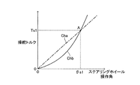
ところで、図9に示すように、ステアリングホイール操作角に対する操舵トルクの特性について、直線的な比例特性(特性Cha)と、下に凸の特性(特性Chb)とを比較する。特性Chaと特性Chbとは、原点(0,0)と、点A(θs1,Ts1)とにおいて交差する。 By the way, as shown in FIG. 9, the linear proportional characteristic (characteristic Cha) and the downward convex characteristic (characteristic Chb) are compared with respect to the characteristic of the steering torque with respect to the steering wheel operation angle. The characteristic Cha and the characteristic Chb intersect at the origin (0, 0) and the point A (θs1, Ts1).
ステアリングホイール操作角を「0」から点Aに対応するθs1まで増大させる場合について考える。この場合、運転者は、ステアリングホイール操作角がθs1に達した時点において、操舵トルクの大きさが同じ(Ts1)であるにもかかわらず、特性Chaの場合よりも特性Chbの場合の方が、操舵トルクが大きいと感じる傾向にある。換言すれば、運転者は、ステアリングホイール操作角の増加に対する操舵トルクの増加勾配が一定の場合よりも、前記増加勾配がステアリングホイール操作角の増大に伴って増大する場合の方が、ステアリングホイール操作角の増大過程において操舵トルクが大きいと感じる傾向にある。以下、この傾向を、「下に凸の特性に起因して操舵トルクが大きいと感じる傾向」とも称呼する。 Consider a case where the steering wheel operating angle is increased from “0” to θs1 corresponding to the point A. In this case, when the steering wheel operating angle reaches θs1, the driver has the characteristic Chb rather than the characteristic Cha, although the steering torque is the same (Ts1). There is a tendency to feel that the steering torque is large. In other words, the driver is more likely to operate the steering wheel when the increase gradient increases as the steering wheel operation angle increases than when the increase gradient of the steering torque with respect to the increase in the steering wheel operation angle is constant. In the process of increasing the angle, the steering torque tends to feel large. Hereinafter, this tendency is also referred to as “a tendency to feel that the steering torque is large due to the downward convex characteristic”.
このことは、この傾向を利用することで、小さい操舵トルクをもって運転者により大きい操舵トルクを感じさせることができることを意味する。 This means that the driver can feel a larger steering torque with a small steering torque by utilizing this tendency.
本発明は、係る傾向を応用して上述した操舵操作部材の操作量の増大を抑制するための抑制力を調整することで、小さい抑制力をもって車両のアンダステアを効果的に抑制することができる車両の操舵制御装置を提供することにある。 The present invention is a vehicle that can effectively suppress understeer of a vehicle with a small suppression force by adjusting the suppression force for suppressing the increase in the operation amount of the steering operation member described above by applying such a tendency. A steering control device is provided.
本発明に係る車両の操舵制御装置は、車両のヨーイング運動に相当する値を取得し前記ヨーイング運動に相当する値に基づいて前記車両のアンダステアの程度を表すアンダステア状態量を演算する状態量演算手段と、前記アンダステア状態量に基づいて前記車両の運転者により操向車輪の転舵のために操作される操舵操作部材の中立位置からの操作量の増大を抑制するための抑制力(前記操作量を減少させる方向の力)を演算する抑制力演算手段と、前記抑制力を前記操舵操作部材に対して前記操作量を減少させる方向に付与する力付与手段と、を備える。 The vehicle steering control device according to the present invention obtains a value corresponding to the yawing motion of the vehicle and calculates an understeer state amount representing the degree of understeer of the vehicle based on the value corresponding to the yawing motion. And a restraining force for suppressing an increase in an operation amount from a neutral position of a steering operation member operated by the driver of the vehicle to steer a steered wheel based on the understeer state amount (the operation amount And a force applying means for applying the suppression force to the steering operation member in a direction of decreasing the operation amount.
本発明に係る操舵制御装置の特徴は、前記抑制力演算手段が、前記アンダステア状態量の増加に対する前記抑制力の増加勾配が前記アンダステア状態量の増加に伴って増大するように前記抑制力を演算するよう構成されたことにある。換言すれば、アンダステア状態量に対する抑制力の特性が下に凸の特性に設定される。 The steering control device according to the present invention is characterized in that the suppression force calculating means calculates the suppression force such that an increase gradient of the suppression force with respect to an increase in the understeer state quantity increases as the understeer state quantity increases. It is configured to do. In other words, the characteristic of the suppression force with respect to the understeer state quantity is set to a downwardly convex characteristic.
即ち、上述した「下に凸の特性に起因して操舵トルクが大きいと感じる傾向」が、アンダステア状態量に対する抑制力の特性に応用されている。従って、アンダステア状態量に対する抑制力の特性が直線的な比例特性の場合に比して、小さい抑制力をもって運転者に大きい操舵操作部材の操作力を感じさせることができる。この結果、小さい抑制力をもって、操舵操作部材の中立位置からの操作量の増大(例えば、ステアリングホイールの「切増し」等)を効果的に抑制することができ、アンダステアを効果的に抑制することができる。 That is, the above-mentioned “tendency to feel that the steering torque is large due to the downwardly convex characteristic” is applied to the characteristic of the suppression force with respect to the understeer state quantity. Therefore, compared with the case where the suppression force characteristic with respect to the understeer state quantity is a linear proportional characteristic, the driver can feel a large operation force of the steering operation member with a small suppression force. As a result, it is possible to effectively suppress an increase in the operation amount from the neutral position of the steering operation member (for example, “increase the steering wheel”) with a small suppression force, and to effectively suppress understeer. Can do.
なお、抑制力が過度に大きいと、運転者により操舵操作部材の操作量が増大されるべき状況(例えば、ステアリングホイールの「切増し」がなされるべき状況)において、運転者が前記操作量を増大し難くなる。従って、フェールセーフの観点から、抑制力は小さい方が好ましい。 Note that if the restraining force is excessively large, the driver increases the operation amount in a situation where the operation amount of the steering operation member should be increased by the driver (for example, a situation where “steering wheel” should be increased). It becomes difficult to increase. Therefore, from the viewpoint of fail-safe, it is preferable that the suppression force is small.
上記本発明に係る操舵制御装置において、(前記操舵操作部材の前記操作量を増大させる方向の)前記運転者による前記操舵操作部材の操作力を取得する取得手段と、前記操作力に基づいて前記運転者による前記操作力を助勢するための助勢力を演算する助勢力演算手段とが備えられ、前記力付与手段が、前記助勢力を前記抑制力に基づいて減少させて得られる力を前記操舵操作部材に対して前記操作量を増大させる方向に付与するように構成されてもよい。 In the steering control device according to the present invention, the acquisition means for acquiring the operation force of the steering operation member by the driver (in the direction of increasing the operation amount of the steering operation member), and the operation force based on the operation force An assisting force calculating means for calculating an assisting force for assisting the operation force by the driver, and the force applying means reduces the assisting force based on the restraining force to obtain the steering force. You may comprise so that the said operation amount may be given to the operation member in the direction which increases.
これによれば、上述した特許文献1に記載の装置のように、抑制力を操舵操作部材に対して前記操作量を減少させる方向に付与するための手法として、運転者の操作力を助勢する助勢力(前記操作量を増大させる方向の力)を抑制力分だけ減少させる手法が採用される。 According to this, as in the device described in Patent Document 1 described above, the driver's operation force is assisted as a technique for applying a suppression force to the steering operation member in a direction to reduce the operation amount. A method of reducing the assisting force (the force in the direction of increasing the operation amount) by the amount of the suppressing force is employed.
次に、上記本発明に係る操舵制御装置において、アンダステアを抑制するために、前記アンダステア状態量に基づいて前記車両の旋回内側の後輪に付与すべき制動力の目標値を演算する制動力演算手段と、前記制動力の目標値に基づいて前記旋回内側の後輪に制動力を付与する制動力制御手段とが備えられる場合を考える。 Next, in the steering control device according to the present invention, in order to suppress understeer, a braking force calculation for calculating a target value of a braking force to be applied to a rear wheel inside the turning of the vehicle based on the understeer state quantity. Let us consider a case in which a means and a braking force control means for applying a braking force to the rear wheel inside the turn based on the target value of the braking force are provided.
この場合、前記抑制力演算手段が、前記アンダステア状態量が第1閾値以下のときに前記抑制力をゼロに演算し、前記アンダステア状態量が前記第1閾値よりも大きいときに前記アンダステア状態量の前記第1閾値からの増大に伴って前記抑制力がゼロから増大するように前記抑制力を演算するよう構成され、前記制動力演算手段が、前記アンダステア状態量が前記第1閾値以下のときに前記制動力の目標値をゼロに演算し、前記アンダステア状態量が前記第1閾値よりも大きいときに前記アンダステア状態量の前記第1閾値からの増大に伴って前記制動力の目標値がゼロから増大するように前記制動力の目標値を演算するよう構成されることが好適である。 In this case, the suppression force calculating means calculates the suppression force to zero when the understeer state quantity is less than or equal to a first threshold, and when the understeer state quantity is greater than the first threshold, The suppression force is calculated so that the suppression force increases from zero with an increase from the first threshold value, and the braking force calculation means is configured when the understeer state quantity is equal to or less than the first threshold value. The target value of the braking force is calculated to be zero, and when the understeer state amount is larger than the first threshold, the target value of the braking force is increased from zero as the understeer state amount increases from the first threshold. It is preferable that the target value of the braking force is calculated so as to increase.
アンダステアを抑制するために旋回内側後輪に制動力を付与すると、車輪のスリップ角の増大に起因してセルフアライニングトルクが減少することで、運転者による操舵操作部材の前記操作力(前記操作量を増大させる方向の力)が減少する(詳細は後述する)。一方、上述のように、前記抑制力を操舵操作部材に対して付与すると、操舵操作部材の前記操作力が増大する。従って、アンダステア状態におけるアンダステア状態量の増大過程において、「旋回内側後輪への制動力の付与」と「操舵操作部材への前記抑制力の付与」の何れか一方が他方より先に開始されると、「旋回内側後輪への制動力の付与」に起因する前記操作力の減少を運転者が感じ取り、運転者に違和感を与えることに繋がる。 When a braking force is applied to the rear inner wheel to suppress understeer, the self-aligning torque is reduced due to an increase in the slip angle of the wheel, so that the driver's operation force (the operation (Force in the direction of increasing the amount) decreases (details will be described later). On the other hand, as described above, when the suppression force is applied to the steering operation member, the operation force of the steering operation member increases. Therefore, in the process of increasing the amount of the understeer state in the understeer state, either “applying the braking force to the turning inner rear wheel” or “applying the suppression force to the steering operation member” is started before the other. Then, the driver perceives the decrease in the operation force caused by “applying the braking force to the turning inner rear wheel”, which leads to an uncomfortable feeling to the driver.
これに対し、上記構成では、「旋回内側後輪への制動力の付与」と「操舵操作部材への前記抑制力の付与」の開始条件(アンダステア状態量が第1閾値を超えること)が同じとされる。従って、アンダステア状態におけるアンダステア状態量の増大過程において、「旋回内側後輪への制動力の付与」と「操舵操作部材への前記抑制力の付与」とが同時に開始される。この結果、「旋回内側後輪への制動力の付与」に起因する前記操作力の減少を運転者が感じ難くなり、運転者に違和感を与えることなく、操舵操作部材に対して前記抑制力を付与することができる。 On the other hand, in the above configuration, the start conditions (the understeer state amount exceeds the first threshold) of “applying the braking force to the rear turning inner wheel” and “applying the suppression force to the steering operation member” are the same. It is said. Accordingly, in the process of increasing the amount of understeer state in the understeer state, “applying a braking force to the turning inner rear wheel” and “applying the suppression force to the steering operation member” are started simultaneously. As a result, it becomes difficult for the driver to feel the decrease in the operation force due to the “applying the braking force to the turning rear rear wheel”, and the suppression force is applied to the steering operation member without causing the driver to feel uncomfortable. Can be granted.
上記のように、「旋回内側後輪への制動力の付与」が実行される場合、前記抑制力演算手段は、前記アンダステア状態量が前記第1閾値よりも大きい範囲に亘って、前記アンダステア状態量に対する前記抑制力が、前記制動力の前記旋回内側の後輪への付与に起因する前記運転者による前記操舵操作部材の操作力(前記操舵操作部材の前記操作量を増大させる方向の力)についての前記アンダステア状態量に対する減少量よりも大きくなるように、前記抑制力を演算するよう構成されることが好適である。 As described above, when “applying a braking force to the turning inner rear wheel” is executed, the suppression force calculation unit is configured to perform the understeer state over a range where the understeer state amount is larger than the first threshold. The restraining force with respect to the amount is an operation force of the steering operation member by the driver (force in a direction to increase the operation amount of the steering operation member) due to the application of the braking force to the rear wheel inside the turn. It is preferable that the suppression force is calculated so as to be larger than an amount of decrease with respect to the understeer state amount of.
上述した「旋回内側後輪への制動力の付与」に起因する前記操作力の減少量は、アンダステア状態量の増大に伴って付与される制動力が増大することに起因して、アンダステア状態量の増大に伴って増大する。上記構成によれば、「旋回内側後輪への制動力の付与」と「操舵操作部材への前記抑制力の付与」とが共に実行されている状態において、「操舵操作部材への前記抑制力の付与」による前記操作力の増大により、「旋回内側後輪への制動力の付与」による前記操作力の減少が常に完全に吸収され得る。即ち、「操舵操作部材への前記抑制力の付与」により、「旋回内側後輪への制動力の付与」による前記操作力の減少を確実に補償することができる。この結果、操舵操作部材の前記操作量の増大(従って、アンダステアの程度の増大)をより確実に抑制することができる。 The amount of decrease in the operation force due to the above-mentioned “applying the braking force to the turning inner rear wheel” is due to the increase in the braking force applied as the understeer state amount increases. It increases with increasing. According to the above configuration, in a state where both “applying the braking force to the rear turning inner wheel” and “applying the suppression force to the steering operation member” are performed, “the suppression force to the steering operation member” By the increase in the operation force due to “applying”, the decrease in the operation force due to “applying the braking force to the turning inner rear wheel” can always be completely absorbed. That is, the “applying the suppression force to the steering operation member” can reliably compensate for the decrease in the operation force due to the “applying the braking force to the turning inner rear wheel”. As a result, an increase in the operation amount of the steering operation member (and hence an increase in the degree of understeer) can be more reliably suppressed.
次に、上記本発明に係る操舵制御装置において、アンダステアを抑制するために、前記アンダステア状態量に基づいて前記操向車輪の転舵角に対する前記操舵操作部材の前記操作量の割合である操舵比の目標値を演算する操舵比演算手段と、前記操舵比の実際値が前記操舵比の目標値となるように前記操舵比を調整する操舵比調整手段とが備えられる場合を考える。 Next, in the steering control device according to the present invention, in order to suppress understeer, a steering ratio that is a ratio of the operation amount of the steering operation member to a turning angle of the steered wheel based on the understeer state amount. Consider a case in which steering ratio calculation means for calculating the target value and steering ratio adjustment means for adjusting the steering ratio so that the actual value of the steering ratio becomes the target value of the steering ratio are considered.
この場合、前記抑制力演算手段が、前記アンダステア状態量が第2閾値以下のときに前記抑制力をゼロに演算し、前記アンダステア状態量が前記第2閾値よりも大きいときに前記アンダステア状態量の前記第2閾値からの増大に伴って前記抑制力がゼロから増大するように前記抑制力を演算するよう構成され、前記操舵比演算手段が、前記アンダステア状態量が前記第2閾値以下のときに前記操舵比の目標値を第1所定値に演算(固定)し、前記アンダステア状態量が前記第2閾値よりも大きいときに前記アンダステア状態量の前記第2閾値からの増大に伴って前記操舵比の目標値が前記第1所定値から増大するように前記操舵比の目標値を演算するよう構成されることが好適である。前記第1閾値と前記第2閾値とは、同じであっても異なっていてもよい。 In this case, the suppression force calculating means calculates the suppression force to zero when the understeer state quantity is less than or equal to a second threshold, and when the understeer state quantity is greater than the second threshold, The suppression force is calculated so that the suppression force increases from zero with an increase from the second threshold value, and the steering ratio calculation means is configured such that the understeer state quantity is equal to or less than the second threshold value. The target value of the steering ratio is calculated (fixed) to a first predetermined value, and when the understeer state quantity is larger than the second threshold value, the steering ratio is increased as the understeer state quantity increases from the second threshold value. It is preferable that the target value of the steering ratio is calculated so that the target value increases from the first predetermined value. The first threshold value and the second threshold value may be the same or different.
運転者が操舵操作部材の前記操作量を一定に維持している状態にて、アンダステアを抑制するために操舵比が増大されると、操向車輪の転舵角が減少する。このことに起因して、運転者による操舵操作部材の前記操作力がステアリング系のヒステリシス分(摩擦分)だけ減少する。一方、上述のように、前記抑制力を操舵操作部材に対して付与すると、操舵操作部材の前記操作力が増大する。従って、アンダステア状態におけるアンダステア状態量の増大過程において、「操舵比の増大」と「操舵操作部材への前記抑制力の付与」の何れか一方が他方より先に開始されると、「操舵比の増大」に起因する前記操作力の減少を運転者が感じ取り、運転者に違和感を与えることに繋がる。 If the steering ratio is increased to suppress understeer in a state where the driver keeps the operation amount of the steering operation member constant, the turning angle of the steered wheels decreases. As a result, the operation force of the steering operation member by the driver is reduced by the hysteresis (friction) of the steering system. On the other hand, as described above, when the suppression force is applied to the steering operation member, the operation force of the steering operation member increases. Therefore, in the process of increasing the amount of understeer state in the understeer state, when one of “increase of the steering ratio” and “applying the suppression force to the steering operation member” is started before the other, The driver perceives the decrease in the operation force due to the “increase”, which leads to an uncomfortable feeling to the driver.
これに対し、上記構成では、「操舵比の増大」と「操舵操作部材への前記抑制力の付与」の開始条件(アンダステア状態量が第2閾値を超えること)が同じとされる。従って、アンダステア状態におけるアンダステア状態量の増大過程において、「操舵比の増大」と「操舵操作部材への前記抑制力の付与」とが同時に開始される。この結果、「操舵比の増大」に起因する前記操作力の減少を運転者が感じ難くなり、運転者に違和感を与えることなく、操舵操作部材に対して前記抑制力を付与することができる。 On the other hand, in the above configuration, the start conditions (the understeer state amount exceeds the second threshold) of “increase in the steering ratio” and “applying the suppression force to the steering operation member” are the same. Accordingly, in the process of increasing the amount of understeer state in the understeer state, “increasing the steering ratio” and “applying the suppression force to the steering operation member” are started simultaneously. As a result, it becomes difficult for the driver to feel the decrease in the operation force due to the “increase in the steering ratio”, and the suppression force can be applied to the steering operation member without causing the driver to feel uncomfortable.
上記のように、「操舵比の増大」が実行される場合、前記抑制力演算手段は、前記アンダステア状態量が前記第2閾値よりも大きい範囲に亘って、前記アンダステア状態量に対する前記抑制力が、前記操舵比の増大に起因する、前記運転者による前記操舵操作部材の操作力(前記操舵操作部材の前記操作量を増大させる方向の力)についての前記アンダステア状態量に対する減少量よりも大きくなるように、前記抑制力を演算するよう構成されることが好適である。 As described above, when the “increase in the steering ratio” is executed, the suppression force calculation unit is configured to reduce the suppression force with respect to the understeer state amount over a range where the understeer state amount is larger than the second threshold. The operation force of the steering operation member by the driver (force in the direction to increase the operation amount of the steering operation member) due to the increase of the steering ratio is larger than the decrease amount with respect to the understeer state amount. Thus, it is preferable to be configured to calculate the suppression force.
上述した「操舵比の増大」に起因する前記操作力の減少量は、アンダステア状態量の増大に伴って操舵比が増大されることに起因して、アンダステア状態量の増大に伴って増大する。上記構成によれば、「操舵比の増大」と「操舵操作部材への前記抑制力の付与」とが共に実行されている状態において、「操舵操作部材への前記抑制力の付与」による前記操作力の増大により、「操舵比の増大」による前記操作力の減少が常に完全に吸収され得る。即ち、「操舵操作部材への前記抑制力の付与」により、「操舵比の増大」による前記操作力の減少を確実に補償することができる。この結果、操舵操作部材の前記操作量の増大(従って、アンダステアの程度の増大)をより確実に抑制することができる。 The amount of decrease in the operating force due to the “increase in the steering ratio” described above increases with an increase in the understeer state amount due to an increase in the steering ratio with an increase in the understeer state amount. According to the above configuration, in a state where both “increase of the steering ratio” and “applying the suppression force to the steering operation member” are performed, the operation by “applying the suppression force to the steering operation member” is performed. Due to the increase in force, the decrease in the operating force due to the “increase in steering ratio” can always be completely absorbed. That is, the “applying the suppression force to the steering operation member” can reliably compensate for the decrease in the operation force due to the “increase in the steering ratio”. As a result, an increase in the operation amount of the steering operation member (and hence an increase in the degree of understeer) can be more reliably suppressed.
以下、本発明による車両の操舵制御装置の各実施形態について図面を参照しつつ説明する。 Embodiments of a vehicle steering control device according to the present invention will be described below with reference to the drawings.
(第1実施形態)
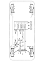
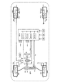
図1は、本発明の第1実施形態に係る操舵制御装置を搭載した車両の概略構成を示している。
(First embodiment)
FIG. 1 shows a schematic configuration of a vehicle equipped with a steering control device according to a first embodiment of the present invention.
第1実施形態では、ステアリングホイールSW(前記「操舵操作部材」に対応)が操作されると、その回転運動がステアリングシャフトSHを介して、ピニオンギアPNに回転運動として伝達される。ピニオンギアPNと螺合するラックRKによって、ピニオンギアPNの回転運動がラックRKの往復運動(車体左右方向の移動)に変換される。このラックRKの移動に応じてラックRKと一体のタイロッドTRが車体左右方向に移動することで、操向車輪(本例では、前輪)WHfl及びWHfrが転舵される。これにより、ステアリングホイールSWの中立位置からの操作角(前記「操作量」に対応)と、操向車輪WHfl及びWHfrの中立位置(直進状態)からの転舵角と、が一対一に決定される。 In the first embodiment, when the steering wheel SW (corresponding to the “steering operation member”) is operated, the rotational motion is transmitted as rotational motion to the pinion gear PN via the steering shaft SH. The rotational movement of the pinion gear PN is converted into the reciprocating movement of the rack RK (movement in the left-right direction of the vehicle body) by the rack RK that is screwed with the pinion gear PN. In response to the movement of the rack RK, the tie rod TR integrated with the rack RK moves in the left-right direction of the vehicle body, whereby the steered wheels (front wheels in this example) WHfl and WHfr are steered. Thereby, the operation angle from the neutral position of the steering wheel SW (corresponding to the “operation amount”) and the steering angle from the neutral position (straight-running state) of the steered wheels WHfl and WHfr are determined on a one-to-one basis. The
タイロッドTRには、減速機Geを介して電気モータMe(第1のモータ)が接続されている。この電気モータMeの駆動力によって運転者のステリングホイール操作力(操舵トルク)が軽減され、所謂パワーステアリング制御(EPS制御)の機能が達成される。 An electric motor Me (first motor) is connected to the tie rod TR via a reduction gear Ge. The driver's steering wheel operating force (steering torque) is reduced by the driving force of the electric motor Me, and a so-called power steering control (EPS control) function is achieved.
ブレーキアクチュエータBRKは、複数の電磁弁、液圧ポンプ、電気モータ等を備えた周知の構成を有している。非制御時では、運転者によるブレーキペダルBPの操作に応じたブレーキ液圧が各車輪のホイールシリンダWC**にそれぞれ供給され、各車輪にブレーキペダル操作に応じた制動トルクが与える。アンチスキッド制御(ABS制御)、トラクション制御(TCS制御)、或いは、車両のアンダステア・オーバステアを抑制する車両安定性制御(ESC制御)などの制動制御時では、ブレーキペダル操作とは独立してホイールシリンダWC**内のブレーキ液圧が車輪毎に制御され、車輪毎に制動トルクが調整され得るようになっている。なお、制動トルクの調整は、ブレーキ液圧を利用することなく、電気ブレーキ装置を利用してなされてもよい。 The brake actuator BRK has a known configuration including a plurality of solenoid valves, a hydraulic pump, an electric motor, and the like. At the time of non-control, the brake fluid pressure corresponding to the operation of the brake pedal BP by the driver is supplied to the wheel cylinder WC ** of each wheel, and the braking torque corresponding to the brake pedal operation is given to each wheel. Wheel cylinder independent of brake pedal operation during braking control such as anti-skid control (ABS control), traction control (TCS control), or vehicle stability control (ESC control) that suppresses vehicle understeer / oversteer The brake fluid pressure in the WC ** is controlled for each wheel, and the braking torque can be adjusted for each wheel. The braking torque may be adjusted using an electric brake device without using the brake fluid pressure.
なお、各種記号等の末尾に付された「**」は、各種記号等が何れの車輪に関するものであるかを示すために各種記号等の末尾に付される「fl」,「fr」等の包括表記である。「fl」は左前輪、「fr」は右前輪、「rl」は左後輪、「rr」は右後輪を示している。例えば、ホイールシリンダWC**は、左前輪ホイールシリンダWCfl, 右前輪ホイールシリンダWCfr, 左後輪ホイールシリンダWCrl, 右後輪ホイールシリンダWCrrを包括的に示している。 In addition, “**” added to the end of various symbols etc. “fl”, “fr” etc. added to the end of various symbols etc. to indicate which wheel the various symbols etc. relate to Is a comprehensive notation. “Fl” indicates the left front wheel, “fr” indicates the right front wheel, “rl” indicates the left rear wheel, and “rr” indicates the right rear wheel. For example, the wheel cylinder WC ** comprehensively indicates a left front wheel wheel cylinder WCfl, a right front wheel wheel cylinder WCfr, a left rear wheel wheel cylinder WCrl, and a right rear wheel wheel cylinder WCrr.
第1実施形態では、車輪速度Vw**を検出する車輪速度センサWS**と、ステアリングホイールSWの(中立位置からの)回転角度(ステアリングホイール操作角θsw)を検出するステアリングホイール回転角度センサSAと、運転者によるステアリングホイールSWの操舵トルクTswを検出する操舵トルクセンサSTと、車体のヨーレイトYrを検出するヨーレイトセンサYRと、車体前後方向における前後加速度Gxを検出する前後加速度センサGXと、車体横方向における横加速度Gyを検出する横加速度センサGYと、前輪(操向車輪)の中立位置からの転舵角δfaを検出する操舵角センサFSと、ホイールシリンダ圧力Pw**を検出するホイールシリンダ圧力センサPS**と、電子制御装置(ECU)とを備えている。 In the first embodiment, a wheel speed sensor WS ** that detects a wheel speed Vw ** and a steering wheel rotation angle sensor SA that detects a rotation angle (from a neutral position) (steering wheel operation angle θsw) of the steering wheel SW. A steering torque sensor ST that detects the steering torque Tsw of the steering wheel SW by the driver, a yaw rate sensor YR that detects the yaw rate Yr of the vehicle body, a longitudinal acceleration sensor GX that detects the longitudinal acceleration Gx in the vehicle body longitudinal direction, A lateral acceleration sensor GY that detects a lateral acceleration Gy in the lateral direction, a steering angle sensor FS that detects a turning angle δfa from a neutral position of a front wheel (steering wheel), and a wheel cylinder that detects a wheel cylinder pressure Pw ** A pressure sensor PS ** and an electronic control unit (ECU) are provided.
ECUは、互いに通信バスCBで接続されたECUb、ECUe、ECUsから構成されたマイクロコンピュータである。ECUは、ブレーキアクチュエータBRK等の各種アクチュエータ、及び前記各種センサと電気的に接続されている。 The ECU is a microcomputer composed of ECUb, ECUe, and ECUs connected to each other via a communication bus CB. The ECU is electrically connected to various actuators such as a brake actuator BRK and the various sensors.
ECUbは、車輪速度センサWS**、前後加速度センサGX、横加速度センサGY等からの信号に基づいてABS制御、TCS制御、ESC制御等の制動制御を実行するようになっている。ECUeは、図示しないエンジンの制御を実行するようになっている。ECUsは、操舵トルクセンサST等からの信号に基づいてEPS制御を実行するようになっている。 The ECU b is adapted to execute braking control such as ABS control, TCS control, and ESC control based on signals from the wheel speed sensor WS **, the longitudinal acceleration sensor GX, the lateral acceleration sensor GY, and the like. The ECU e performs control of an engine (not shown). The ECUs execute EPS control based on signals from the steering torque sensor ST and the like.
(アンダステア抑制制御)
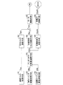
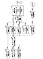
次に、図2を参照しながら、第1実施形態が実行するアンダステア抑制制御について説明する。第1実施形態では、アンダステア抑制制御として、操舵トルク制御と制動力制御とが実行される。先ず、操舵トルク制御について説明する。
(Understeer suppression control)
Next, the understeer suppression control executed by the first embodiment will be described with reference to FIG. In the first embodiment, steering torque control and braking force control are executed as understeer suppression control. First, steering torque control will be described.
操舵トルク取得手段A1では、操舵トルクセンサSTにより、運転者によるステアリングホイールSWの操舵トルクTsw(前記「操作力」に対応)が取得される。EPSトルク演算手段A2では、取得された操舵トルクTswに基づいて、運転者の操舵トルクを軽減するためのパワーステアリングトルク(EPSトルク)の目標値Tepsが演算される。Tepsは、Tswが大きいほどより大きい値に演算される。Tepsは、θswを増大させる方向の値である。 In the steering torque acquisition means A1, the steering torque Tsw (corresponding to the “operation force”) of the steering wheel SW by the driver is acquired by the steering torque sensor ST. The EPS torque calculation means A2 calculates a target value Teps of power steering torque (EPS torque) for reducing the driver's steering torque based on the acquired steering torque Tsw. Teps is calculated to a larger value as Tsw is larger. Teps is a value in the direction of increasing θsw.
実ヨーイング挙動取得手段A3では、実際のヨーイング挙動VMa(例えば、ヨーレイトYr)が取得される。目標ヨーイング挙動演算手段A4では、目標とする車両挙動(目標ヨーイング挙動)VMtが演算される。VMtは、例えば、ステアリングホイール操作角θsw、車輪速度Vw**から得られる車体速度等に基づいて演算される。 The actual yawing behavior acquisition means A3 acquires the actual yawing behavior VMa (for example, yaw rate Yr). In the target yawing behavior calculation means A4, a target vehicle behavior (target yawing behavior) VMt is calculated. VMt is calculated based on, for example, the vehicle body speed obtained from the steering wheel operation angle θsw and the wheel speed Vw **.
アンダステア状態量演算手段A5では、VMaとVMtとの比較結果(例えば、VMaとVMtとの偏差)に基づいて、アンダステアの程度を表すアンダステア状態量Jrusが演算される。また、Jrusは、VMtを用いずにVMaに基づいて演算され得る。Jrusは、例えば、スタビリティファクターKhや、アンダステア係数Kusであり、ヨーレイトYrに基づいて演算される値である。 The understeer state quantity calculating means A5 calculates an understeer state quantity Jrus representing the degree of understeer based on the comparison result between VMa and VMt (for example, the deviation between VMa and VMt). Jrus can be calculated based on VMa without using VMt. Jrus is, for example, a stability factor Kh or an understeer coefficient Kus, and is a value calculated based on the yaw rate Yr.
切増抑制トルク演算手段A6では、Jrusに基づいて、切増し抑制トルク(抑制トルク)Tusが、図3の実線に示した特性(Ch1、又はCh2)に従って演算される。この特性については後に詳述する。そして、モータ駆動手段A7では、TepsからTusを減算して得られる、電気モータMeの駆動制御用の目標値Tmtr(=Teps−Tus)に基づいて、電気モータMeが駆動される。 The increase suppression torque calculating means A6 calculates the increase suppression torque (suppression torque) Tus based on Jrus according to the characteristic (Ch1 or Ch2) shown by the solid line in FIG. This characteristic will be described in detail later. In the motor driving means A7, the electric motor Me is driven based on a target value Tmtr (= Teps−Tus) for driving control of the electric motor Me obtained by subtracting Tus from Teps.
これにより、Tmtrに相当する駆動力がタイロッドTRに付与されて、運転者による操舵トルクが軽減される。即ち、運転者による操舵トルクを軽減するためのトルクが、EPSトルクTepsから抑制トルクTusを減じた値に設定される。換言すれば、ステアリングホイール操作角を維持するため、運転者は、Tusに相当する操舵トルクを余分に必要とする。 As a result, a driving force corresponding to Tmtr is applied to the tie rod TR, and the steering torque by the driver is reduced. That is, the torque for reducing the steering torque by the driver is set to a value obtained by subtracting the suppression torque Tus from the EPS torque Teps. In other words, in order to maintain the steering wheel operation angle, the driver needs an extra steering torque corresponding to Tus.
以上のように、TswとJrusとに基づいて、操舵トルク制御が実行される。この結果、アンダステア状態において、ステアリングホイールSWの「切増し」が抑制されて、アンダステアの程度の増大が抑制され得る。 As described above, the steering torque control is executed based on Tsw and Jrus. As a result, in the understeer state, the “steering” of the steering wheel SW is suppressed, and an increase in the degree of understeer can be suppressed.
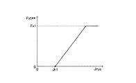
加えて、車両のアンダステアを抑制する制動力制御(ESC制御)が、Jrusに基づいて行われる。即ち、各輪制動力演算手段A8では、Jrusに基づいて、図4に示した特性に従って、各車輪の制動力の目標値Fxt**が演算される。これにより、Fxt**は、Jrusが閾値Jr1(前記「第1閾値」に対応)以下のときにゼロに演算され、JrusがJr1よりも大きいときにJrusのJr1からの増大に伴ってゼロから増大するように(ただし、値Fx1以下に制限される)演算される。 In addition, braking force control (ESC control) that suppresses vehicle understeer is performed based on Jrus. That is, each wheel braking force calculation means A8 calculates the target value Fxt ** of the braking force of each wheel according to the characteristic shown in FIG. 4 based on Jrus. As a result, Fxt ** is calculated to be zero when Jrus is equal to or less than the threshold value Jr1 (corresponding to the “first threshold value”). When Jrus is larger than Jr1, it increases from zero as Jrus increases from Jr1. The calculation is performed so as to increase (however, limited to the value Fx1 or less).
制動力制御手段A9では、Fxt**に基づいてブレーキアクチュエータBRKが駆動される。これにより、各車輪の制動力がFxt**と一致するように調整される。この結果、運転者によるブレーキペダルBPの操作とは独立して、後輪の制動力(特に、旋回内側の後輪の制動力)が増加させられる。以上のように、「Jrus>Jr1」を開始条件として、Jrusに基づいて、制動力制御が実行される。上述の操舵トルク制御におけるTusの付与に加えて、この制動力制御によっても、アンダステアが抑制される。 In the braking force control means A9, the brake actuator BRK is driven based on Fxt **. As a result, the braking force of each wheel is adjusted to coincide with Fxt **. As a result, the braking force of the rear wheels (particularly, the braking force of the rear wheels inside the turn) is increased independently of the operation of the brake pedal BP by the driver. As described above, braking force control is executed based on Jrus using “Jrus> Jr1” as a start condition. Understeer is suppressed by this braking force control in addition to the application of Tus in the steering torque control described above.
(抑制トルクTusの設定)
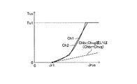
次に、図3に示した抑制トルクTusの特性について説明する。図3の実線に示すように、Tusは、アンダステア状態量Jrusが閾値Jr1(前記「第1閾値」に対応、図4のJr1と同じ値)以下のときにゼロに演算され、JrusがJr1よりも大きいときにJrusのJr1からの増大に伴ってゼロから増大するように(ただし、値Tu1以下に制限される)演算される。即ち、「Jrus>Jr1」を開始条件として、操舵トルク制御におけるTusの付与が開始される。
(Setting of suppression torque Tus)
Next, the characteristics of the suppression torque Tus shown in FIG. 3 will be described. As shown by the solid line in FIG. 3, Tus is calculated to be zero when the understeer state quantity Jrus is equal to or less than a threshold value Jr1 (corresponding to the “first threshold value” and the same value as Jr1 in FIG. 4). Is also calculated so that it increases from zero as Jrus increases from Jr1 (however, it is limited to the value Tu1 or less). That is, the application of Tus in the steering torque control is started using “Jrus> Jr1” as a start condition.
加えて、Jrus>Jr1の場合において、Jrusの増加に対するTusの増加勾配がJrusの増加に伴って増大するようにTusが演算される。即ち、Jrusに対するTusの特性が下に凸の特性に設定される。この特性は、滑らかな曲線で構成される特性Ch1、或いは、複数の直線を組み合わせて得られる特性Ch2等により実現され得る。 In addition, in the case of Jrus> Jr1, Tus is calculated so that the increase gradient of Tus with respect to the increase of Jrus increases with the increase of Jrus. That is, the Tus characteristic with respect to Jrus is set to a downwardly convex characteristic. This characteristic can be realized by a characteristic Ch1 configured by a smooth curve, a characteristic Ch2 obtained by combining a plurality of straight lines, or the like.
この結果、運転者は、Jrusの増大過程においてTusの変化を敏感に感じ取ることができ、運転者は、上述した「下に凸の特性に起因して操舵トルクが大きいと感じる傾向」と同様の傾向を得ることができる。即ち、Jrusに対するTusの特性が直線的な比例特性の場合に比して、小さいTusをもって運転者に大きい操舵トルクを感じさせることができる。この結果、小さいTusをもって、ステアリングホイールSWの「切増し」が効果的に抑制されて、アンダステアの程度の増大が効果的に抑制され得る。 As a result, the driver can sensitively detect the change in Tus in the process of increasing Jrus, and the driver is similar to the above-mentioned “prone to feel that the steering torque is large due to the downwardly convex characteristic”. A trend can be obtained. That is, compared with the case where the characteristic of Tus with respect to Jrus is a linear proportional characteristic, the driver can feel a large steering torque with a small Tus. As a result, with a small Tus, “increase” of the steering wheel SW can be effectively suppressed, and an increase in the degree of understeer can be effectively suppressed.
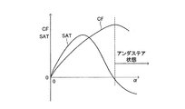
ところで、上述の制動力制御により、アンダステアを抑制するために旋回内側後輪に制動力が付与されると、アンダステアの程度の減少により車体のスリップ角βが増大し、この結果、操向車輪(前輪)のスリップ角αも増大する。ここで、スリップ角αと、コーナリングフォースCF及びセルフアライニングトルクSATとは、図5に示す関係にある。 By the way, when braking force is applied to the turning rear rear wheel to suppress understeer by the above-described braking force control, the slip angle β of the vehicle body increases due to the decrease in the degree of understeer, and as a result, the steered wheel ( The slip angle α of the front wheel also increases. Here, the slip angle α, the cornering force CF, and the self-aligning torque SAT have the relationship shown in FIG.
図5に示すように、アンダステアの状態では、前輪のコーナリングフォースCFは既に飽和している状態にある。従って、アンダステアの状態においてスリップ角αが増大すると、セルフアライニングトルクSATが減少し、運転者による操舵トルクが減少する。一方、上述の操舵トルク制御において抑制トルクTusが付与されると、運転者による操舵トルクが増大する。 As shown in FIG. 5, in the understeer state, the cornering force CF of the front wheel is already saturated. Accordingly, when the slip angle α increases in the understeer state, the self-aligning torque SAT decreases and the steering torque by the driver decreases. On the other hand, when the suppression torque Tus is applied in the steering torque control described above, the steering torque by the driver increases.
よって、アンダステアの状態におけるアンダステア状態量Jrusの増大過程において、「旋回内側後輪への制動力の付与」と「抑制トルクTusの付与」の何れか一方が他方より先に開始されると(両者が同時に開始されないと)、「旋回内側後輪への制動力の付与」に起因する操舵トルクの減少を運転者が感じ取り、運転者に違和感を与えることに繋がる。 Therefore, in the process of increasing the understeer state amount Jrus in the understeer state, when either “applying braking force to the turning inner rear wheel” or “applying suppression torque Tus” is started before the other (both Is not started at the same time), the driver feels a decrease in the steering torque due to “applying braking force to the rear wheels on the inside of the turn”, which leads to an uncomfortable feeling to the driver.
これに対し、第1実施形態では、上述のように、「旋回内側後輪への制動力の付与」と「抑制トルクTusの付与」の開始条件(「Jrus>Jr1」)が同じである。従って、アンダステア状態におけるJrusの増大過程において、「旋回内側後輪への制動力の付与」と「抑制トルクTusの付与」とが同時に開始される。この結果、「旋回内側後輪への制動力の付与」に起因する操舵トルクの減少を運転者が感じ難くなり、運転者に違和感を与えることなく、抑制力Tusの付与が実行され得る。 On the other hand, in the first embodiment, as described above, the start conditions (“Jrus> Jr1”) of “applying braking force to the turning inner rear wheel” and “applying suppression torque Tus” are the same. Accordingly, in the process of increasing Jrus in the understeer state, “applying a braking force to the turning inner rear wheel” and “applying the suppression torque Tus” are started simultaneously. As a result, it becomes difficult for the driver to feel a decrease in the steering torque due to “applying the braking force to the turning inner rear wheel”, and the application of the suppression force Tus can be performed without causing the driver to feel uncomfortable.
また、アンダステア状態量Jrusの増大に伴って付与される制動力が増大することに起因して、上述した「旋回内側後輪への制動力の付与」に起因する操舵トルクの減少量は、Jrusの増大に伴って増大する。図3に破線で示した特性Chbrは、Jrusに対する操舵トルクの減少量の特性を示している。なお、この特性Chbrは、実験等を通じて予め得ることができる。 Further, the amount of decrease in the steering torque caused by the above-mentioned “applying the braking force to the turning inner rear wheel” due to the increase in the braking force applied with the increase in the understeer state amount Jrus is Jrus It increases with increasing. A characteristic Chbr indicated by a broken line in FIG. 3 indicates a characteristic of a reduction amount of the steering torque with respect to Jrus. This characteristic Chbr can be obtained in advance through experiments or the like.
ここで、図3から理解できるように、JrusがJr1よりも大きい範囲に亘って、Jrusに対するTus(特性Ch1、又はCh2)が、Jrusに対する前記「操舵トルクの減少量」(特性Chbr)よりも大きい。従って、「旋回内側後輪への制動力の付与」と「抑制トルクTusの付与」とが共に実行されている状態(Jrus>Jr1の場合)において、「抑制トルクTusの付与」による操舵トルクの増大により、「旋回内側後輪への制動力の付与」による操舵トルクの減少が完全に吸収され得る。 Here, as can be understood from FIG. 3, over a range where Jrus is larger than Jr1, Tus (characteristic Ch1 or Ch2) with respect to Jrus is larger than the “amount of decrease in steering torque” (characteristic Chbr) with respect to Jrus. large. Therefore, in the state where both “applying braking force to the rear-turning rear wheel” and “applying suppression torque Tus” (when Jrus> Jr1), the steering torque of “applying suppression torque Tus” By the increase, the decrease in the steering torque due to “applying the braking force to the rear wheels on the inside of the turn” can be completely absorbed.
この結果、「旋回内側後輪への制動力の付与」に起因する操舵トルクの減少を運転者がより一層感じ難くなる。加えて、「旋回内側後輪への制動力の付与」に起因する操舵トルクの減少が「抑制トルクTusの付与」に起因する操舵トルクの増大を上回ることに伴うステアリングホイールSWの「切増し」の発生が確実に抑制され得るから、これによっても、アンダステアの程度の増大が確実に抑制され得る。 As a result, it becomes more difficult for the driver to feel a decrease in steering torque caused by “applying braking force to the rear turning inner wheel”. In addition, “increase” of the steering wheel SW due to the decrease in the steering torque caused by “applying braking force to the rear turning inner wheel” exceeds the increase in steering torque caused by “applying the suppression torque Tus”. Therefore, the increase of the degree of understeer can be reliably suppressed.
以上、本発明の第1実施形態に係る操舵制御装置によれば、アンダステア抑制制御として、操舵トルク制御(「抑制トルクTusの付与」)と制動力制御(「旋回内側後輪への制動力の付与」)とが実行される。操舵トルク制御では、運転者による操舵トルクTswに基づいて操舵トルクを軽減するためのEPSトルクTepsが演算され、アンダステアの程度を表すアンダステア状態量Jrusに基づいてステアリングホイールの「切増し」を抑制するための抑制トルクTusが演算される。運転者による操舵トルクを軽減するためのトルクが、(Teps−Tus)に調整される。これにより、ステアリングホイール操作角を維持するため、運転者は、Tusに相当する操舵トルクを余分に必要とする。ここで、Jrusに対するTusの特性が下に凸の特性に設定される。 As described above, according to the steering control device according to the first embodiment of the present invention, as the understeer suppression control, the steering torque control ("applying the suppression torque Tus") and the braking force control ("the braking force applied to the turning rear rear wheel"). Grant "). In the steering torque control, an EPS torque Teps for reducing the steering torque is calculated based on the steering torque Tsw by the driver, and the “steering wheel” is suppressed based on the understeer state quantity Jrus representing the degree of understeer. Therefore, the suppression torque Tus is calculated. Torque for reducing the steering torque by the driver is adjusted to (Teps-Tus). Accordingly, in order to maintain the steering wheel operation angle, the driver needs an extra steering torque corresponding to Tus. Here, the characteristic of Tus with respect to Jrus is set to a downward convex characteristic.
この結果、Jrusの増大過程においてTusの変化を敏感に感じ取ることができ、Jrusに対するTusの特性が直線的な比例特性の場合に比して、小さいTusをもって運転者に大きい操舵トルクを感じさせることができる。この結果、小さいTusをもって、ステアリングホイールSWの「切増し」が効果的に抑制されて、アンダステアの程度の増大が効果的に抑制され得る。 As a result, the change in Tus can be perceived sensitively in the process of increasing Jrus, and the driver feels a large steering torque with a smaller Tus than when the characteristic of Tus with respect to Jrus is a linear proportional characteristic. Can do. As a result, with a small Tus, “increase” of the steering wheel SW can be effectively suppressed, and an increase in the degree of understeer can be effectively suppressed.
制動力制御では、Jrusに基づいて決定される制動力が旋回内側後輪に付与される。ここで、「旋回内側後輪への制動力の付与」と「抑制トルクTusの付与」との開始条件(「Jrus>Jr1」)が同じであり、且つ、Jrusに対するTusの特性(Ch1、又はCh2)が、Jrusに対する、「旋回内側後輪への制動力の付与」に起因する「操舵トルクの減少量」の特性(Chbr)よりも大きい。従って、「旋回内側後輪への制動力の付与」に起因する操舵トルクの減少を運転者が感じ難くなり、運転者に違和感を与えることなく、抑制力Tusの付与が実行され得る。 In the braking force control, a braking force determined based on Jrus is applied to the turning inner rear wheel. Here, the start conditions (“Jrus> Jr1”) for “applying the braking force to the rear wheel on the inside of the turn” and “applying the suppression torque Tus” are the same, and the characteristics of the Tus with respect to Jrus (Ch1, or Ch2) is larger than the characteristic (Chbr) of “amount of decrease in steering torque” caused by “applying a braking force to the turning inner rear wheel” with respect to Jrus. Therefore, it becomes difficult for the driver to feel a decrease in the steering torque due to “applying the braking force to the rear inner wheel”, and the suppression force Tus can be applied without causing the driver to feel uncomfortable.
(第2実施形態)
次に、本発明の第2実施形態に係る操舵制御装置について説明する。この第2実施形態は、アンダステア抑制制御として、上記第1実施形態における操舵トルク制御(「抑制トルクTusの付与」)と制動力制御(「旋回内側後輪への制動力の付与」)とに加えて、操舵比制御(「操舵比の増大」)が実行される点が上記第1実施形態と異なる。以下、係る相違点についてのみ説明する。
(Second Embodiment)
Next, a steering control device according to a second embodiment of the present invention will be described. In the second embodiment, as the understeer suppression control, the steering torque control (“applying suppression torque Tus”) and the braking force control (“applying braking force to the turning inner rear wheel”) in the first embodiment are used. In addition, the point that the steering ratio control (“increase of the steering ratio”) is executed is different from the first embodiment. Only such differences will be described below.
図6は、第2実施形態に係る操舵制御装置を搭載した車両の概略構成を示している。この第2実施形態では、図1に示した上記第1実施形態に係る装置に対して、ステアリングシャフトSHが、アッパステアリングシャフトSHuとロアステアリングシャフトSHlとに分割され、これらの間にアクチュエータVGが介装され、且つ、ECUb等と互いに通信バスCBで接続されたECUvによってVGが制御される点が異なる。 FIG. 6 shows a schematic configuration of a vehicle equipped with the steering control device according to the second embodiment. In the second embodiment, the steering shaft SH is divided into an upper steering shaft SHu and a lower steering shaft SHl with respect to the apparatus according to the first embodiment shown in FIG. The difference is that the VG is controlled by an ECU v that is interposed and connected to the ECU b and the like via a communication bus CB.
アクチュエータVGは、電気モータMv(第2のモータ)と、ギア機構Gvとから構成されていて、モータMvの回転角度を制御することで、SHuに対するSHlの相対的な回転角度(相対角)を調整可能に構成されている。この相対角を制御することで、前輪WHfr,WHflの(中立位置からの)舵角に対する、ステアリングホイールSWの(中立位置からの)操作角の割合(操舵比、ステアリングギア比、操舵ギア比などと呼ばれる)が変更可能に構成されている。 The actuator VG includes an electric motor Mv (second motor) and a gear mechanism Gv. By controlling the rotation angle of the motor Mv, the relative rotation angle (relative angle) of SHl with respect to SHu is set. It is configured to be adjustable. By controlling this relative angle, the ratio of the operation angle (from the neutral position) of the steering wheel SW to the steering angle (from the neutral position) of the front wheels WHfr, WHfl (from the neutral position) (steering ratio, steering gear ratio, steering gear ratio, etc.) It is configured to be changeable.
このことに関連して、図2に対応する図7に示すように、第2実施形態では、操舵比演算手段A10、ステアリングホイール操作角取得手段A11、及び相対角演算手段A12が追加され、モータ駆動手段A7において、第1のモータMeの制御部に加えて第2のモータMvの制御部が設けられている。 In this regard, as shown in FIG. 7 corresponding to FIG. 2, in the second embodiment, a steering ratio calculation means A10, a steering wheel operation angle acquisition means A11, and a relative angle calculation means A12 are added, and the motor In the driving means A7, a control unit for the second motor Mv is provided in addition to the control unit for the first motor Me.
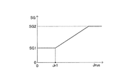
操舵比演算手段A10では、アンダステア状態量Jrusに基づいて、図8に示した特性に従って、操舵比の目標値SGが演算される。これにより、SGは、Jrusが閾値Jr1(前記「第2閾値」に対応)以下のときに値SG1(前記「第1所定値」に対応)に演算され、JrusがJr1よりも大きいときにJrusのJr1からの増大に伴ってSG1から増大するように(ただし、値SG2以下に制限される)演算される。 In the steering ratio calculation means A10, the target value SG of the steering ratio is calculated according to the characteristics shown in FIG. 8 based on the understeer state quantity Jrus. Thus, SG is calculated to a value SG1 (corresponding to the “first predetermined value”) when Jrus is equal to or less than a threshold value Jr1 (corresponding to the “second threshold value”), and Jrus is calculated when Jrus is greater than Jr1. Is increased from SG1 as Jr1 increases (however, it is limited to the value SG2 or less).
ステアリングホイール操作角取得手段A11では、ステアリングホイール回転角度センサSAにより、ステアリングホイール操作角θswが取得される。このθswにSGの逆数(1/SG)が乗算されて前輪舵角の目標値δftが決定される。相対角演算手段A12では、このδftを達成するための相対角の目標値θrelが演算される。 In the steering wheel operation angle acquisition means A11, the steering wheel operation angle θsw is acquired by the steering wheel rotation angle sensor SA. This θsw is multiplied by the reciprocal of SG (1 / SG) to determine the target value δft of the front wheel steering angle. In the relative angle calculation means A12, a target value θrel of the relative angle for achieving this δft is calculated.
モータ駆動手段A7の第2のモータMvの制御部では、θrelに基づいて電気モータMvが駆動される。これにより、相対角がθrelと一致するように調整される。この結果、「Jrus>Jr1」を開始条件として、操舵比がSG1から増大させられる。 In the control unit of the second motor Mv of the motor driving means A7, the electric motor Mv is driven based on θrel. Thereby, the relative angle is adjusted to coincide with θrel. As a result, the steering ratio is increased from SG1 with “Jrus> Jr1” as a start condition.
操舵比が大きい値となると、ステアリングホイール操作角に対する前輪舵角(従って、前輪のスリップ角α)が小さくなり、且つ、ステアリングホイール操作角の増加に対する前輪舵角(従って、前輪のスリップ角α)の増加量が小さくなる。これにより、アンダステアが抑制される。このように、第2実施形態では、上述した操舵トルク制御(「抑制トルクTusの付与」)、制動力制御(「旋回内側後輪への制動力の付与」)に加えて、この操舵比制御(「操舵比の増大」)によっても、アンダステアが抑制される。 When the steering ratio becomes a large value, the front wheel rudder angle with respect to the steering wheel operating angle (accordingly, the front wheel slip angle α) becomes small, and the front wheel rudder angle with respect to increase of the steering wheel operating angle (accordingly, the front wheel slip angle α). The amount of increase becomes smaller. Thereby, understeer is suppressed. Thus, in the second embodiment, in addition to the steering torque control (“applying the suppression torque Tus”) and the braking force control (“applying the braking force to the turning inner rear wheel”), the steering ratio control is performed. ("Increase in steering ratio") also suppresses understeer.
ところで、操舵比が変更される場合、電気モータMvの駆動力により車輪のセルフアライニングトルクに対抗して前輪が操舵される。このときの反力は、運転者によるステアリングホイールSWの保舵力(操舵トルク)(及び、電気モータMeの駆動力)によって支えられる。ここで、例えば、アンダステア状態において運転者によりステアリングホイール操作角が一定に保持されている場合において操舵比が増大すると、前輪舵角は中立位置(δfa=0)の方向へ切り戻される。このことに起因して、ステアリング系のヒステリシス分(摩擦分)だけ運転者による操舵トルクが減少する。一方、上述の操舵トルク制御において抑制トルクTusが付与されると、運転者による操舵トルクが増大する。 By the way, when the steering ratio is changed, the front wheels are steered against the self-aligning torque of the wheels by the driving force of the electric motor Mv. The reaction force at this time is supported by the steering force (steering torque) of the steering wheel SW (and the driving force of the electric motor Me) by the driver. Here, for example, when the steering wheel operating angle is kept constant by the driver in the understeer state and the steering ratio increases, the front wheel steering angle is switched back toward the neutral position (δfa = 0). As a result, the steering torque by the driver is reduced by the hysteresis (friction) of the steering system. On the other hand, when the suppression torque Tus is applied in the steering torque control described above, the steering torque by the driver increases.
よって、アンダステアの状態におけるアンダステア状態量Jrusの増大過程において、「操舵比の増大」と「抑制トルクTusの付与」の何れか一方が他方より先に開始されると(両者が同時に開始されないと)、「操舵比の増大」に起因する操舵トルクの減少を運転者が感じ取り、運転者に違和感を与えることに繋がる。 Therefore, in the process of increasing the understeer state amount Jrus in the understeer state, when either “increase in the steering ratio” or “applying the suppression torque Tus” is started before the other (if both are not started simultaneously) In this case, the driver feels a decrease in the steering torque due to the “increase in the steering ratio”, which leads to an uncomfortable feeling for the driver.
これに対し、第2実施形態では、上述のように、「操舵比の増大」と「抑制トルクTusの付与」の開始条件(「Jrus>Jr1」)が同じである。従って、アンダステア状態におけるJrusの増大過程において、「操舵比の増大」と「抑制トルクTusの付与」とが同時に開始される。この結果、「操舵比の増大」に起因する操舵トルクの減少を運転者が感じ難くなり、運転者に違和感を与えることなく、抑制力Tusの付与が実行され得る。 On the other hand, in the second embodiment, as described above, the start conditions (“Jrus> Jr1”) of “increase in the steering ratio” and “apply the suppression torque Tus” are the same. Therefore, in the process of increasing Jrus in the understeer state, “increasing the steering ratio” and “applying the suppression torque Tus” are started simultaneously. As a result, it becomes difficult for the driver to feel a decrease in the steering torque due to the “increase in the steering ratio”, and the application of the restraining force Tus can be performed without causing the driver to feel uncomfortable.
また、アンダステア状態量Jrusの増大に伴って操舵比が増大することに起因して、上述した「操舵比の増大」に起因する操舵トルクの減少量は、Jrusの増大に伴って増大する。図3に破線で示した特性Chvgは、Jrusに対する操舵トルクの減少量の特性を示している。なお、この特性Chvgは、実験等を通じて予め得ることができる。 Further, due to the increase in the steering ratio as the understeer state amount Jrus increases, the amount of decrease in the steering torque due to the above-described “increase in steering ratio” increases as Jrus increases. A characteristic Chvg indicated by a broken line in FIG. 3 indicates a characteristic of a reduction amount of the steering torque with respect to Jrus. This characteristic Chvg can be obtained in advance through experiments or the like.
ここで、図3から理解できるように、JrusがJr1よりも大きい範囲に亘って、Jrusに対するTus(特性Ch1、又はCh2)が、Jrusに対する前記「操舵トルクの減少量」(特性Chvg)よりも大きい。従って、「操舵比の増大」と「抑制トルクTusの付与」とが共に実行されている状態(Jrus>Jr1の場合)において、「抑制トルクTusの付与」による操舵トルクの増大により、「操舵比の増大」による操舵トルクの減少が完全に吸収され得る。 Here, as understood from FIG. 3, over a range where Jrus is larger than Jr1, Tus (characteristic Ch1 or Ch2) with respect to Jrus is larger than the “amount of decrease in steering torque” (characteristic Chvg) with respect to Jrus. large. Therefore, in a state where both “increase of the steering ratio” and “applying the suppression torque Tus” are executed (when Jrus> Jr1), the “steering ratio” is increased by the increase of the steering torque by “applying the suppression torque Tus”. The decrease in steering torque due to the “increase” can be completely absorbed.
この結果、「操舵比の増大」に起因する操舵トルクの減少を運転者がより一層感じ難くなる。加えて、「操舵比の増大」に起因する操舵トルクの減少が「抑制トルクTusの付与」に起因する操舵トルクの増大を上回ることに伴うステアリングホイールSWの「切増し」の発生が確実に抑制され得るから、これによっても、アンダステアの程度の増大が確実に抑制され得る。 As a result, it becomes more difficult for the driver to feel a decrease in the steering torque due to the “increase in the steering ratio”. In addition, it is possible to reliably suppress the occurrence of “increase” in the steering wheel SW due to the decrease in the steering torque due to the “increase in the steering ratio” exceeding the increase in the steering torque due to the “applying the suppression torque Tus”. As a result, the increase in the degree of understeer can be reliably suppressed.
本発明は上記各実施形態に限定されることはなく、本発明の範囲内において種々の変形例を採用することができる。例えば、上記各実施形態においては、ステアリングホイールSWと操向車輪WHfl及びWHfrとが機械的に接続されているが、ステアリングホイールSWと操向車輪WHfl及びWHfrとが機械的に接続されていない所謂ステア・バイ・ワイヤ方式(即ち、ステアリングホイールSWの操作角θswを示す電気信号に基づいて前輪舵角の制御を行う機構)が採用されてもよい。この場合、前記「操舵操作部材」として、ステアリングホイールSWに代えて棒状部材(所謂、ジョイスティック)が使用されてもよい。 The present invention is not limited to the above embodiments, and various modifications can be adopted within the scope of the present invention. For example, in each of the above embodiments, the steering wheel SW and the steered wheels WHfl and WHfr are mechanically connected, but the steering wheel SW and the steered wheels WHfl and WHfr are not mechanically connected. A steer-by-wire system (that is, a mechanism for controlling the front wheel steering angle based on an electrical signal indicating the operation angle θsw of the steering wheel SW) may be employed. In this case, a rod-shaped member (so-called joystick) may be used as the “steering operation member” instead of the steering wheel SW.
また、上記第2実施形態においては、JrusがJr1よりも大きい範囲に亘って、Jrusに対するTus(特性Ch1、又はCh2)が、Jrusに対する、「操舵比の増大」に起因する前記「操舵トルクの減少量」(特性Chvg)よりも大きいように設定されているが、JrusがJr1よりも大きい範囲に亘って、Jrusに対するTus(特性Ch1、又はCh2)が、Jrusに対する「操舵比の増大」に起因する「操舵トルクの減少量」(特性Chvg)とJrusに対する「旋回内側後輪への制動力の付与」に起因する「操舵トルクの減少量」(特性Chbr)の和(Chbr+Chvg)よりも大きいように設定されてもよい。 Further, in the second embodiment, over a range where Jrus is larger than Jr1, Tus (characteristic Ch1 or Ch2) with respect to Jrus is “the increase in steering ratio” with respect to Jrus. Although it is set to be larger than the “decrease amount” (characteristic Chvg), Tus (characteristic Ch1 or Ch2) with respect to Jrus becomes “increase in steering ratio” with respect to Jrus over a range where Jrus is larger than Jr1. It is larger than the sum (Chbr + Chvg) of the “steering torque reduction amount” (characteristic Chvg) and the “steering torque reduction amount” (characteristic Chbr) resulting from “applying braking force to the turning inner rear wheel” to Jrus. It may be set as follows.
また、上記第2実施形態においては、アンダステア抑制制御として、操舵トルク制御(「抑制トルクTusの付与」)、制動力制御(「旋回内側後輪への制動力の付与」)、及び、操舵比制御(「操舵比の増大」)が実行されているが、操舵トルク制御(「抑制トルクTusの付与」)、及び操舵比制御(「操舵比の増大」)のみが実行されてもよい。 In the second embodiment, as the understeer suppression control, steering torque control (“applying suppression torque Tus”), braking force control (“applying braking force to the turning inner rear wheel”), and steering ratio Although control ("increase steering ratio") is executed, only steering torque control ("applying suppression torque Tus") and steering ratio control ("increase steering ratio") may be executed.
加えて、上記各実施形態においては、電気モータMeの駆動制御用の目標値Tmtr(=Teps−Tus)に基づいて電気モータMeが駆動され、運転者による操舵トルクを軽減するためのトルク(ステアリングホイール操作角を増大させる方向のトルク)が、EPSトルクTepsから抑制トルクTusを減じた値に設定されているが、電気モータMeの駆動制御用の目標値Tmtr(=Tus)に基づいて電気モータMeが駆動され、運転者による操舵トルクを増大するためのトルク(ステアリングホイール操作角を減少させる方向のトルク)が、抑制トルクTusと等しい値に設定されてもよい。 In addition, in each of the above embodiments, the electric motor Me is driven based on the target value Tmtr (= Teps−Tus) for driving control of the electric motor Me, and torque (steering for reducing the steering torque by the driver). The torque in the direction of increasing the wheel operation angle) is set to a value obtained by subtracting the suppression torque Tus from the EPS torque Teps, but the electric motor is based on the target value Tmtr (= Tus) for driving control of the electric motor Me. Me is driven, and the torque for increasing the steering torque by the driver (torque in the direction of decreasing the steering wheel operation angle) may be set to a value equal to the suppression torque Tus.
BRK…ブレーキアクチュエータ、ECU…電子制御装置、Me…電気モータ、Mv…電気モータ、SW…ステアリングホイール、SA…ステアリングホイール回転角度センサ、ST…操舵トルクセンサ、YR…ヨーレイトセンサ、WS**…車輪速度センサ BRK ... Brake actuator, ECU ... Electronic control device, Me ... Electric motor, Mv ... Electric motor, SW ... Steering wheel, SA ... Steering wheel rotation angle sensor, ST ... Steering torque sensor, YR ... Yaw rate sensor, WS ** ... Wheel Speed sensor
Claims (6)
前記アンダステア状態量に基づいて、前記車両の運転者により操向車輪(WHf*)の転舵のために操作される操舵操作部材(SW)の中立位置からの操作量(θsw)の増大を抑制するための抑制力(Tus)を演算する抑制力演算手段(A6)と、
前記抑制力を、前記操舵操作部材に対して前記操作量を減少させる方向に付与する力付与手段(A7)と、
を備えた車両の操舵制御装置において、
前記抑制力演算手段は、
前記アンダステア状態量の増加に対する前記抑制力の増加勾配が前記アンダステア状態量の増加に伴って増大するように前記抑制力を演算するよう構成された車両の操舵制御装置。 A state quantity calculating means (A3, which obtains a value (VMa) corresponding to the yawing movement of the vehicle and calculates an understeer state quantity (Jrus) representing the degree of understeer of the vehicle based on the value corresponding to the yawing movement. A4, A5) and
Based on the understeer state amount, an increase in the operation amount (θsw) from the neutral position of the steering operation member (SW) operated by the driver of the vehicle to steer the steering wheel (WHf *) is suppressed. Suppression force calculating means (A6) for calculating the suppression force (Tus) for
Force applying means (A7) for applying the suppression force to the steering operation member in a direction to reduce the operation amount;
In a vehicle steering control device comprising:
The suppression force calculating means is
A vehicle steering control device configured to calculate the suppression force such that an increase gradient of the suppression force with respect to an increase in the understeer state amount increases as the understeer state amount increases.
前記操作力に基づいて、前記運転者による前記操作力を助勢するための助勢力(Teps)を演算する助勢力演算手段(A2)と、
前記車両のヨーイング運動に相当する値(VMa)を取得し、前記ヨーイング運動に相当する値に基づいて、前記車両のアンダステアの程度を表すアンダステア状態量(Jrus)を演算する状態量演算手段(A3,A4,A5)と、
前記アンダステア状態量に基づいて、前記操舵操作部材の中立位置からの操作量(θsw)の増大を抑制するための抑制力(Tus)を演算する抑制力演算手段(A6)と、
前記助勢力を前記抑制力に基づいて減少させて得られる力(Tmtr)を、前記操舵操作部材に対して前記操作量を増大させる方向に付与する力付与手段(A7)と、
を備えた車両の操舵制御装置において、
前記抑制力演算手段は、
前記アンダステア状態量の増加に対する前記抑制力の増加勾配が前記アンダステア状態量の増加に伴って増大するように前記抑制力を演算するよう構成された車両の操舵制御装置。 An acquisition means (A1) for acquiring an operation force (Tsw) by the driver of a steering operation member (SW) that is operated to steer a steered wheel (WHf *) by a driver of the vehicle;
Based on the operating force, an assisting force calculating means (A2) for calculating an assisting force (Teps) for assisting the operating force by the driver;
A state quantity calculating means (A3) for obtaining a value (VMa) corresponding to the yawing movement of the vehicle and calculating an understeer state quantity (Jrus) representing the degree of understeer of the vehicle based on the value corresponding to the yawing movement. , A4, A5) and
Based on the understeer state amount, a suppression force calculation means (A6) for calculating a suppression force (Tus) for suppressing an increase in the operation amount (θsw) from the neutral position of the steering operation member;
A force applying means (A7) for applying a force (Tmtr) obtained by reducing the assisting force based on the restraining force in a direction to increase the operation amount with respect to the steering operation member;
In a vehicle steering control device comprising:
The suppression force calculating means is
A vehicle steering control device configured to calculate the suppression force such that an increase gradient of the suppression force with respect to an increase in the understeer state amount increases as the understeer state amount increases.
前記アンダステア状態量に基づいて、前記車両の旋回内側の後輪に付与すべき制動力の目標値(Fxt**)を演算する制動力演算手段(A8)と、
前記制動力の目標値に基づいて前記旋回内側の後輪に制動力を付与する制動力制御手段(A9)と、
を備え、
前記抑制力演算手段は、
前記アンダステア状態量が第1閾値(Jr1)以下のときに前記抑制力をゼロに演算し、前記アンダステア状態量が前記第1閾値よりも大きいときに前記アンダステア状態量の前記第1閾値からの増大に伴って前記抑制力がゼロから増大するように前記抑制力を演算するよう構成され、
前記制動力演算手段は、
前記アンダステア状態量が前記第1閾値(Jr1)以下のときに前記制動力の目標値をゼロに演算し、前記アンダステア状態量が前記第1閾値よりも大きいときに前記アンダステア状態量の前記第1閾値からの増大に伴って前記制動力の目標値がゼロから増大するように前記制動力の目標値を演算するよう構成された車両の操舵制御装置。 A vehicle steering control device according to claim 1 or claim 2,
Braking force calculation means (A8) for calculating a target value (Fxt **) of the braking force to be applied to the rear wheel inside the turning of the vehicle based on the understeer state quantity;
Braking force control means (A9) for applying a braking force to the rear wheel inside the turn based on the target value of the braking force;
With
The suppression force calculating means is
The suppression force is calculated to be zero when the understeer state quantity is equal to or less than a first threshold (Jr1), and when the understeer state quantity is greater than the first threshold, the understeer state quantity increases from the first threshold. And is configured to calculate the suppression force such that the suppression force increases from zero,
The braking force calculation means
When the understeer state quantity is less than or equal to the first threshold (Jr1), the target value of the braking force is calculated to be zero, and when the understeer state quantity is greater than the first threshold, the first value of the understeer state quantity is calculated. A vehicle steering control device configured to calculate a target value of the braking force such that the target value of the braking force increases from zero as the threshold value increases.
前記抑制力演算手段は、
前記アンダステア状態量が前記第1閾値よりも大きい範囲に亘って、
前記アンダステア状態量に対する前記抑制力(Ch1,Ch2)が、
前記制動力の前記旋回内側の後輪への付与に起因する、前記運転者による前記操舵操作部材の操作力についての前記アンダステア状態量に対する減少量(Chbr)よりも大きくなるように、前記抑制力を演算するよう構成された車両の操舵制御装置。 In the vehicle steering control device according to claim 3,
The suppression force calculating means is
Over a range where the understeer state quantity is larger than the first threshold,
The inhibitory force (Ch1, Ch2) against the understeer state quantity is
The restraining force so as to be larger than a reduction amount (Chbr) with respect to the understeer state amount of the operation force of the steering operation member by the driver due to the application of the braking force to the rear wheel inside the turn. A steering control device for a vehicle configured to calculate
前記アンダステア状態量に基づいて、前記操向車輪の転舵角(δfa)に対する前記操舵操作部材の前記操作量(θsw)の割合である操舵比の目標値(SG)を演算する操舵比演算手段(A10)と、
前記操舵比の実際値が前記操舵比の目標値となるように前記操舵比を調整する操舵比調整手段(A11,A12)と、
を備え、
前記抑制力演算手段は、
前記アンダステア状態量が第2閾値(Jr1)以下のときに前記抑制力をゼロに演算し、前記アンダステア状態量が前記第2閾値よりも大きいときに前記アンダステア状態量の前記第2閾値からの増大に伴って前記抑制力がゼロから増大するように前記抑制力を演算するよう構成され、
前記操舵比演算手段は、
前記アンダステア状態量が前記第2閾値(Jr1)以下のときに前記操舵比の目標値を第1所定値(SG1)に演算し、前記アンダステア状態量が前記第2閾値よりも大きいときに前記アンダステア状態量の前記第2閾値からの増大に伴って前記操舵比の目標値が前記第1所定値から増大するように前記操舵比の目標値を演算するよう構成された車両の操舵制御装置。 A vehicle steering control device according to claim 1 or claim 2,
Steering ratio calculation means for calculating a target value (SG) of a steering ratio that is a ratio of the operation amount (θsw) of the steering operation member to the steering angle (δfa) of the steered wheel based on the understeer state amount (A10) and
Steering ratio adjusting means (A11, A12) for adjusting the steering ratio so that the actual value of the steering ratio becomes the target value of the steering ratio;
With
The suppression force calculating means is
When the understeer state quantity is equal to or less than a second threshold (Jr1), the suppression force is calculated to be zero, and when the understeer state quantity is greater than the second threshold, the understeer state quantity increases from the second threshold. And is configured to calculate the suppression force such that the suppression force increases from zero,
The steering ratio calculating means includes
When the understeer state quantity is less than or equal to the second threshold value (Jr1), the target value of the steering ratio is calculated to a first predetermined value (SG1), and when the understeer state quantity is greater than the second threshold value, the understeer state quantity is calculated. A vehicle steering control device configured to calculate the target value of the steering ratio so that the target value of the steering ratio increases from the first predetermined value as the state quantity increases from the second threshold value.
前記抑制力演算手段は、
前記アンダステア状態量が前記第2閾値よりも大きい範囲に亘って、
前記アンダステア状態量に対する前記抑制力(Ch1,Ch2)が、
前記操舵比の増大に起因する、前記運転者による前記操舵操作部材の操作力についての前記アンダステア状態量に対する減少量(Chvg)よりも大きくなるように、前記抑制力を演算するよう構成された車両の操舵制御装置。 The vehicle steering control device according to claim 5,
The suppression force calculating means is
Over a range where the understeer state quantity is larger than the second threshold,
The inhibitory force (Ch1, Ch2) against the understeer state quantity is
A vehicle configured to calculate the suppression force so as to be larger than a reduction amount (Chvg) of the operation force of the steering operation member by the driver with respect to the understeer state amount due to the increase in the steering ratio. Steering control device.
Priority Applications (1)
| Application Number | Priority Date | Filing Date | Title |
|---|---|---|---|
| JP2008075936A JP5251195B2 (en) | 2008-03-24 | 2008-03-24 | Vehicle steering control device |
Applications Claiming Priority (1)
| Application Number | Priority Date | Filing Date | Title |
|---|---|---|---|
| JP2008075936A JP5251195B2 (en) | 2008-03-24 | 2008-03-24 | Vehicle steering control device |
Publications (2)
| Publication Number | Publication Date |
|---|---|
| JP2009227135A true JP2009227135A (en) | 2009-10-08 |
| JP5251195B2 JP5251195B2 (en) | 2013-07-31 |
Family
ID=41243054
Family Applications (1)
| Application Number | Title | Priority Date | Filing Date |
|---|---|---|---|
| JP2008075936A Expired - Fee Related JP5251195B2 (en) | 2008-03-24 | 2008-03-24 | Vehicle steering control device |
Country Status (1)
| Country | Link |
|---|---|
| JP (1) | JP5251195B2 (en) |
Citations (4)
| Publication number | Priority date | Publication date | Assignee | Title |
|---|---|---|---|---|
| JPH1120728A (en) * | 1997-07-03 | 1999-01-26 | Honda Motor Co Ltd | Vehicle steering system |
| JP2003252084A (en) * | 2002-03-04 | 2003-09-09 | Mitsubishi Motors Corp | Integrated steering and braking control device |
| JP2007126015A (en) * | 2005-11-04 | 2007-05-24 | Advics:Kk | Center-of-gravity position lateral acceleration acquisition device for vehicle and motion control device for vehicle |
| JP2007131251A (en) * | 2005-11-14 | 2007-05-31 | Advics:Kk | Vehicle motion controller |
-
2008
- 2008-03-24 JP JP2008075936A patent/JP5251195B2/en not_active Expired - Fee Related
Patent Citations (4)
| Publication number | Priority date | Publication date | Assignee | Title |
|---|---|---|---|---|
| JPH1120728A (en) * | 1997-07-03 | 1999-01-26 | Honda Motor Co Ltd | Vehicle steering system |
| JP2003252084A (en) * | 2002-03-04 | 2003-09-09 | Mitsubishi Motors Corp | Integrated steering and braking control device |
| JP2007126015A (en) * | 2005-11-04 | 2007-05-24 | Advics:Kk | Center-of-gravity position lateral acceleration acquisition device for vehicle and motion control device for vehicle |
| JP2007131251A (en) * | 2005-11-14 | 2007-05-31 | Advics:Kk | Vehicle motion controller |
Also Published As
| Publication number | Publication date |
|---|---|
| JP5251195B2 (en) | 2013-07-31 |
Similar Documents
| Publication | Publication Date | Title |
|---|---|---|
| US8165756B2 (en) | Steering control device for vehicle | |
| JP5251067B2 (en) | Vehicle steering control device | |
| JP4924378B2 (en) | Vehicle travel control device | |
| US7418329B2 (en) | Steering control apparatus for a vehicle | |
| EP1510438B1 (en) | Control device for vehicle power steering | |
| US8892305B2 (en) | Motion control device for vehicle | |
| JP5516146B2 (en) | Vehicle travel control device | |
| KR100816308B1 (en) | Controller of electric power steering device of vehicle having wheel slip controller acting on steered wheel | |
| US7337873B2 (en) | Steering control apparatus for a vehicle | |
| JP5431745B2 (en) | Vehicle motion control device | |
| US11702073B2 (en) | System and method for controlling a vehicle steering system | |
| JP4172361B2 (en) | Control device for electric power steering device | |
| JP5115276B2 (en) | Vehicle steering control device | |
| JP5251195B2 (en) | Vehicle steering control device | |
| JP4296970B2 (en) | Vehicle behavior control device | |
| JP5163752B2 (en) | Power steering device | |
| JP5194430B2 (en) | Four-wheel steering control device for vehicle | |
| JP5194949B2 (en) | Vehicle steering control device | |
| JP2006015871A (en) | Reaction force control device | |
| JP5194429B2 (en) | Four-wheel steering control device for vehicle | |
| JP4811196B2 (en) | Vehicle steering control device | |
| JP2012106588A (en) | Vehicle steering force control system | |
| JP4685407B2 (en) | Vehicle behavior control device | |
| JP4284211B2 (en) | Vehicle steering control device | |
| JP2022083564A (en) | Steering power controller, steering controller and steer by wire system |
Legal Events
| Date | Code | Title | Description |
|---|---|---|---|
| A621 | Written request for application examination |
Free format text: JAPANESE INTERMEDIATE CODE: A621 Effective date: 20110318 |
|
| A131 | Notification of reasons for refusal |
Free format text: JAPANESE INTERMEDIATE CODE: A131 Effective date: 20121128 |
|
| A977 | Report on retrieval |
Free format text: JAPANESE INTERMEDIATE CODE: A971007 Effective date: 20121130 |
|
| A521 | Request for written amendment filed |
Free format text: JAPANESE INTERMEDIATE CODE: A523 Effective date: 20130125 |
|
| TRDD | Decision of grant or rejection written | ||
| A01 | Written decision to grant a patent or to grant a registration (utility model) |
Free format text: JAPANESE INTERMEDIATE CODE: A01 Effective date: 20130319 |
|
| A61 | First payment of annual fees (during grant procedure) |
Free format text: JAPANESE INTERMEDIATE CODE: A61 Effective date: 20130401 |
|
| R150 | Certificate of patent or registration of utility model |
Ref document number: 5251195 Country of ref document: JP Free format text: JAPANESE INTERMEDIATE CODE: R150 Free format text: JAPANESE INTERMEDIATE CODE: R150 |
|
| FPAY | Renewal fee payment (event date is renewal date of database) |
Free format text: PAYMENT UNTIL: 20160426 Year of fee payment: 3 |
|
| LAPS | Cancellation because of no payment of annual fees |