JP2009223040A - Image display device and method - Google Patents
Image display device and method Download PDFInfo
- Publication number
- JP2009223040A JP2009223040A JP2008068147A JP2008068147A JP2009223040A JP 2009223040 A JP2009223040 A JP 2009223040A JP 2008068147 A JP2008068147 A JP 2008068147A JP 2008068147 A JP2008068147 A JP 2008068147A JP 2009223040 A JP2009223040 A JP 2009223040A
- Authority
- JP
- Japan
- Prior art keywords
- image
- modulation
- brightness
- surrounding area
- image display
- Prior art date
- Legal status (The legal status is an assumption and is not a legal conclusion. Google has not performed a legal analysis and makes no representation as to the accuracy of the status listed.)
- Withdrawn
Links
Images


Abstract
Description
本発明は、被投射面に画像を投写表示させる技術に関し、特に、被投射面上の画像の台形歪みを補正する技術に関する。 The present invention relates to a technique for projecting and displaying an image on a projection surface, and more particularly to a technique for correcting trapezoidal distortion of an image on the projection surface.
投写型プロジェクタを用いてスクリーンや壁等の被投射面に画像を投写する際に、プロジェクタと被投射面との相対的な位置関係に起因して、被投射面に表示された画像(以下、「表示画像」と呼ぶ)が台形に歪むことがある。このような表示画像の台形歪みを補正する技術として、液晶パネルを用いたプロジェクタにおいて、液晶パネル上に形成する画像を台形状に変形(縮小)させることで、表示画像が矩形となるようにする技術が知られている(下記特許文献1参照)。
When projecting an image onto a projection surface such as a screen or a wall using a projection projector, an image displayed on the projection surface (hereinafter, referred to as “projection surface”) is caused by the relative positional relationship between the projector and the projection surface. May be distorted into a trapezoid. As a technique for correcting such trapezoidal distortion of a display image, in a projector using a liquid crystal panel, an image formed on the liquid crystal panel is deformed (reduced) into a trapezoidal shape so that the display image becomes rectangular. A technique is known (see
上記台形歪み補正において、液晶パネルでは、台形状に変形(縮小)された画像が形成される領域の周りに表示すべき画像が存在しない領域(以下、「周囲領域」と呼ぶ)が生じることとなる。従来、この周囲領域を全白や全黒など特定の一色に固定的に設定していた。しかしながら、このように周囲領域を特定色に設定して一定の明るさのままで長期間投写すると、液晶内部において不純物イオンによる分極が発生するなどして画像の表示の跡が残ってしまい、いわゆる画像の焼き付きが発生するおそれがあった。 In the above trapezoidal distortion correction, in the liquid crystal panel, an area where an image to be displayed does not exist (hereinafter referred to as “peripheral area”) is generated around an area where an image deformed (reduced) in a trapezoidal shape is formed. Become. Conventionally, this surrounding area has been fixedly set to a specific color such as all white or all black. However, if the surrounding area is set to a specific color and projected for a long period of time with a constant brightness, polarization due to impurity ions occurs in the liquid crystal, so that a trace of image display remains. There was a risk of image burn-in.
なお、上述の問題は、投写型プロジェクタに限らず、リアプロジェクタにおいても発生し得る。また、液晶パネルを用いた画像表示装置に限らず、焼き付きが発生し得る他の画像表示装置(例えば、三管式(CRT)プロジェクタ等)においても、台形歪み補正を行う場合に発生し得る。 Note that the above-described problem can occur not only in a projection projector but also in a rear projector. In addition to image display devices using a liquid crystal panel, other image display devices (for example, a three-tube (CRT) projector, etc.) where burn-in may occur may occur when trapezoidal distortion correction is performed.
本発明は、画像表示装置における台形歪み補正による画像の焼き付きを抑制可能な技術を提供することを目標とする。 An object of the present invention is to provide a technique capable of suppressing image burn-in by trapezoidal distortion correction in an image display device.
本発明は、上述の課題の少なくとも一部を解決するためになされたものであり、以下の形態又は適用例として実現することが可能である。 SUMMARY An advantage of some aspects of the invention is to solve at least a part of the problems described above, and the invention can be implemented as the following forms or application examples.
[適用例1]被投写面に画像を表示させる画像表示装置であって、光源部と、入力画像データに基づき変調用画像を形成するための変調用画像形成領域を有し、前記変調用画像を用いて前記光源部が射出する光を画像光に変調する光変調部と、前記変調用画像形成領域において前記入力画像データの表す対象画像の形状を変形させて前記変調用画像を形成することにより、前記被投写面に表示される画像の台形歪みを補正する台形歪み補正部と、前記変調用画像形成領域のうち、変形後の前記対象画像が形成される有効画像形成領域を除いた周囲領域の明るさを変化させる明るさ調整部と、を備える、画像表示装置。 Application Example 1 An image display device that displays an image on a projection surface, includes a light source unit and a modulation image forming region for forming a modulation image based on input image data, and the modulation image A light modulating unit that modulates light emitted from the light source unit into image light using a light source, and deforming a shape of a target image represented by the input image data in the modulation image forming region to form the modulation image. A trapezoidal distortion correction unit that corrects a trapezoidal distortion of an image displayed on the projection surface, and a periphery excluding an effective image forming area in which the modified target image is formed in the modulation image forming area An image display device comprising: a brightness adjustment unit that changes the brightness of the area.
適用例1の画像表示装置は、変調用画像形成領域のうち周囲領域の明るさを変化させるので、周囲領域の明るさが一定の状態を維持することが回避することができ、台形歪み補正による画像の焼き付きを抑制することができる。 Since the image display device of Application Example 1 changes the brightness of the surrounding area in the modulation image forming area, it can be avoided that the brightness of the surrounding area is kept constant, and by the trapezoidal distortion correction. Image burn-in can be suppressed.
[適用例2]請求項1に記載の画像表示装置であって、さらに、前記入力画像データに基づき、前記対象画像の明るさに関する特徴量を取得する特徴量取得部を備え、前記明るさ調整部は、前記特徴量に応じて前記周囲領域の明るさを変化させる、画像表示装置。
Application Example 2 The image display device according to
このようにすることで、対象画像の明るさに応じて周囲領域の明るさを変化させるので、被投写面において、周囲領域に対応する画像の明るさを対象画像の明るさに応じて変化させることができる。 In this way, since the brightness of the surrounding area is changed according to the brightness of the target image, the brightness of the image corresponding to the surrounding area is changed according to the brightness of the target image on the projection surface. be able to.
[適用例3]請求項2に記載の画像表示装置において、前記明るさ調整部は、前記特徴量の示す明るさがより明るい場合に、前記周囲領域の明るさをより明るくなるように変化させる、画像表示装置。 Application Example 3 In the image display device according to claim 2, when the brightness indicated by the feature amount is brighter, the brightness adjustment unit changes the brightness of the surrounding area to be brighter. , Image display device.
このようにすることで、被投写面において、対象画像の明るさに合わせて周囲領域に対応する画像の明るさを変化させることができる。したがって、例えば、対象画像が非常に暗いのにも関わらず周囲領域に対応する画像が非常に明るくなる等によって、観察者に違和感を与えることを抑制することができる。 In this way, the brightness of the image corresponding to the surrounding area can be changed on the projection surface in accordance with the brightness of the target image. Therefore, for example, it is possible to prevent the viewer from feeling uncomfortable due to the fact that the image corresponding to the surrounding area becomes very bright even though the target image is very dark.
[適用例4]被投射面に画像を表示させる画像表示装置を用いた画像表示方法であって、前記画像表示装置は、光源部と、入力画像データに基づき変調用画像を形成するための変調用画像形成領域を有し、前記変調用画像を用いて前記光源部が射出する光を画像光に変調する光変調部と、を備えており、(a)前記変調用画像形成領域において前記入力画像データの表す対象画像の形状を変形させて前記変調用画像を形成することにより、前記被投写面に表示される画像の台形歪みを補正する工程と、(b)前記変調用画像形成領域のうち、変形後の前記対象画像が形成される有効画像形成領域を除いた周囲領域の明るさを変化させる工程と、を備える、画像表示方法。 Application Example 4 An image display method using an image display device that displays an image on a projection surface, the image display device including a light source unit and modulation for forming a modulation image based on input image data A light modulation unit that modulates light emitted from the light source unit into image light using the modulation image, and (a) the input in the modulation image formation region (B) correcting the trapezoidal distortion of the image displayed on the projection surface by deforming the shape of the target image represented by the image data to form the modulation image; And a step of changing brightness of a surrounding area excluding an effective image forming area in which the target image after deformation is formed.
適用例4の画像表示方法では、変調用画像形成領域のうち周囲領域の明るさを変化させるので、周囲領域の明るさが一定の状態を維持することを回避することができ、台形歪み補正による画像の焼き付きを抑制することができる。 In the image display method of Application Example 4, since the brightness of the surrounding area in the modulation image forming area is changed, it is possible to avoid the brightness of the surrounding area from being kept constant, and by the trapezoidal distortion correction. Image burn-in can be suppressed.
なお、本発明は、種々の形態で実現することが可能であり、例えば、上記画像処理方法または画像処理装置の機能を実現するためのコンピュータプログラム、そのコンピュータプログラムを記録した記録媒体、等の形態で実現することができる。 The present invention can be realized in various forms, for example, forms of a computer program for realizing the functions of the image processing method or the image processing apparatus, a recording medium on which the computer program is recorded, and the like. Can be realized.
以下、本発明を実施するための最良の形態を実施例に基づいて以下の順序で説明する。
A.第1の実施例:
B.第2の実施例:
C.変形例:
Hereinafter, the best mode for carrying out the present invention will be described in the following order based on examples.
A. First embodiment:
B. Second embodiment:
C. Variations:
A.第1の実施例:
A1.装置構成:
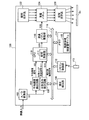
図1は、本発明の第1の実施例における画像表示装置としてのプロジェクタの概略構成を示す説明図である。このプロジェクタ100は、スクリーンScに画像を投写表示させる投写型プロジェクタである。プロジェクタ100は、A/D変換部102と、平均輝度検出回路104と、台形歪み補正回路106と、傾き検出部108と、CPU110と、リモコン制御部112と、リモコン113と、メモリ114と、液晶パネル駆動部116と、照明光学系122と、透過型の液晶パネル124と、投写光学系126と、を備えている。
A. First embodiment:
A1. Device configuration:
FIG. 1 is an explanatory diagram showing a schematic configuration of a projector as an image display apparatus in the first embodiment of the present invention. The
A/D変換部102は、DVDプレーヤやコンピュータなどの外部機器(図示省略)から入力される映像信号に対して必要に応じてA/D変換を行い、デジタル映像信号SI1を出力する。なお、以下では、デジタル映像信号SI1は、NTSC規格の信号であり、1秒間に30枚のフレーム単位の画像データを示す信号であるものとして説明する。平均輝度検出回路104は、入力されたデジタル映像信号SI1から1フレームごとの平均輝度を検出して、平均輝度信号SI5を出力する。台形歪み補正回路106は、プロジェクタ100がスクリーンScに画像を投写した際に生じる台形歪みを補正する。台形歪み補正回路106は、台形歪み補正を行った後のフレーム画像信号SI10と、台形エリア指定信号SI11とを出力する。前述の平均輝度信号SI5及び台形エリア指定信号SI11の詳細については後述する。
The A /
メモリ114には、周囲領域輝度値テーブル115が格納されている。また、メモリ114には図示しない画像投写制御用プログラムが格納されており、CPU110は、このプログラムを実行することによって投写制御部111として機能することとなる。CPU110には、前述の平均輝度信号SI5と台形歪み補正後の映像信号SI10と台形エリア指定信号SI11とが入力される。投写制御部111は、台形歪み補正後の映像信号SI10を受信して、コントラストやシャープネス等の調整を行うと共に周囲領域(後述)の明るさの調整を行った上で、変調用画像信号SI20を液晶パネル駆動部116に供給する。液晶パネル駆動部116は、変調用画像信号SI20に応じた駆動信号SI30を液晶パネル124に供給することで液晶パネル124を駆動する。
The
照明光学系122は、光源としてのメタルハライドランプ(図示省略)や、リフレクタ(図示省略)などを備え、照明光を液晶パネル124に導く。液晶パネル124は、液晶パネル駆動部116から入力される駆動信号SI30に基づいて変調用画像を形成して、この変調用画像によって照明光を変調して画像光を生成する。投写光学系126は、図示せざる投写レンズや絞りを有しており、画像光をスクリーンScに向かって射出する。
The illumination
傾き検出部108は、プロジェクタ100の光軸が水平面となす傾き角度(以下、「傾き角度」と呼ぶ)を検出する。傾き検出部108としては、例えば、加速度センサを用いることができる。リモコン制御部112は、リモコン113を通じたユーザからの指示を受信し、内部バス118を介してCPU110に伝える。
The
上記構成を有するプロジェクタ100は、スクリーンScに対して垂直に画像光を投写しない場合には台形歪み補正を行い、スクリーンSc上において表示すべき画像が矩形になるようにしている。このとき、プロジェクタ100では、後述する画像表示処理を実行することで、液晶パネル124のうち、台形状に変形された画像の周りに位置する周囲領域において画像の焼き付きが発生しないように構成されている。
The
なお、前述の液晶パネル124は、請求項における光変調部に相当する。また、台形歪み補正回路106は請求項における台形歪み補正部に、平均輝度検出回路104は請求項における特徴量取得部に、投写制御部111は請求項における明るさ調整部に、それぞれ相当する。
The
A2.画像表示処理:
図2は、プロジェクタ100において実行される画像表示処理の手順を示すフローチャートである。ユーザがリモコン113を用いて映像(画像)を指定して画像投写の実行を指示すると、プロジェクタ100において画像表示処理が実行される。
A2. Image display processing:
FIG. 2 is a flowchart showing a procedure of image display processing executed in
ステップS105では、投写制御部111(図1)は、傾き検出部108を用いてプロジェクタ100の傾き角度を取得して、得られた傾き角度を台形歪み補正回路106に伝える。ステップS110では、台形歪み補正回路106は、受信した傾き角度に基づき、入力されるフレーム画像について台形歪み補正を実行し、台形歪み補正後のフレーム画像信号SI10をCPU110に送信する。
In step S <b> 105, the projection control unit 111 (FIG. 1) acquires the tilt angle of the
図3(A)は、プロジェクタ100とスクリーンScとの位置関係の一例を示す説明図である。図3(B)は、図3(A)に示す位置関係において台形歪み補正前に液晶パネルに形成される変調用画像とスクリーンScに投写される表示画像とを示す説明図である。図3(C)は、図3(A)に示す位置関係において台形歪み補正後に液晶パネルに形成される変調用画像とスクリーンScに投写される表示画像とを示す説明図である。なお、図3(B),(C)では、全白の画像(映像)を投写表示させる場合を例として記載している。また、図3(B),(C)では、比較的暗い環境においてスクリーンScに投写した場合を示しており、スクリーンScの被投写面のうち表示画像の周りは暗くなっている。
FIG. 3A is an explanatory diagram illustrating an example of the positional relationship between the
台形歪み補正回路106(図1)は、液晶パネル124に形成する変調用画像において、表示すべき画像(以下、「対象画像」とも呼ぶ)の形状を変形させることで台形歪み補正を実行する。具体的には、以下のごとく台形歪み補正を実行する。図3(B)の例では、台形歪み補正前において、液晶パネル124の変調用画像形成領域IFいっぱいに対象画像PFが形成されている。すなわち、対象画像PFがそのまま変調用画像PD1となっている。ここで、図3(A)に示すように、プロジェクタ100は、上向きに傾いて投写しておりスクリーンScに対して垂直に投写していない。この場合、スクリーンSc上に投写される表示画像PA1は、図3(B)に示すように上底が下底よりも長い台形となる。そこで、台形歪み補正回路106は、図3(C)に示すように、変調用画像形成領域IFにおいて、対象画像の形状を上底が下底よりも短い台形となるように変形(縮小)させる。このとき、変調用画像形成領域IFには、変形後の対象画像PFaの周りに表示すべき画像が存在しない周囲領域PFbが生じることとなる。すなわち、変形後の対象画像PFaと周囲領域PFbの画像とで変調用画像PD2が構成される。このような変調用画像PD2を用いて投写すると、スクリーンSc上の表示画像PA2は、変形後の対象画像PFaに対応する表示画像部PAaと周囲領域PFbの画像に対応する表示画像部PAbとで構成される。前述のように、変形後の対象画像PFaは上底が短い台形に変形されているので、プロジェクタ100が上向きに傾いて投写することで表示画像部PAaは矩形となり、表示すべき対象画像は矩形に表示される。なお、前述の変調用画像形成領域IFは、液晶パネル124の全面よりも各辺から所定数のドットずつ(例えば2ドットずつ)内側となる矩形領域となっている。液晶パネル124の全面における変調用画像形成領域IFの大きさは任意に設定可能である。
The trapezoidal distortion correction circuit 106 (FIG. 1) performs trapezoidal distortion correction by changing the shape of an image to be displayed (hereinafter also referred to as “target image”) in the modulation image formed on the
ここで、プロジェクタ100の光軸が水平面となす角度θ(傾き角度θ:図3(A))が大きいほど、スクリーンScにおける台形歪みは大きくなる。そこで、台形歪み補正回路106は、傾き角度θに応じて対象画像を変形するようにしている。具体的には、以下のようにして変形する。予め、傾き角度θを変えて投写する実験を行い、各傾き角度θにおいて表示画像が矩形となる際の液晶パネル124における対象画像の各頂点の座標を求める。そして、傾き角度θと対象画像の各頂点の座標とを対応付けたテーブル(図示省略)を作成してメモリ114に格納しておき、ステップS105によって得られた傾き角度θに基づき、かかるテーブルを参照して対象画像を変形させる。なお、画像を変形(縮小)させる具体的な方法については、画素補間等の公知の技術(例えば、特開2002−135690号公報や特開2004−15648号公報参照。)を用いて行うことができる。
Here, the larger the angle θ (tilt angle θ: FIG. 3A) that the optical axis of the
ステップS115(図2)では、台形歪み補正回路106は、台形歪み補正後のフレーム画像についての台形エリア指定信号SI11をCPU110に通知する。「台形エリア指定信号SI11」とは、台形歪み補正後のフレーム画像において周囲領域に対応する画像と変形後の対象画像とを特定するための信号である。具体的には、図3(C)の例では、変形後の対象画像PFaを構成する画素について「0」を、周囲領域PFbに対応する画像を構成する画素について「1」をそれぞれ示す信号として、台形エリア指定信号SI11が構成することができる。
In step S115 (FIG. 2), the trapezoidal
ステップS120(図2)では、平均輝度検出回路104(図1)は、入力されるフレーム画像の平均輝度を算出し、平均輝度信号SI5としてCPU110に通知する。平均輝度は、各画素についてR(赤),G(緑),B(青)の各画素値を所定の算出式に代入して輝度値(Y)を求め、全ての画素の輝度値(Y)の平均として求めることができる。なお、この平均輝度は、請求項における「明るさに関する特徴量」に相当する。
In step S120 (FIG. 2), the average luminance detection circuit 104 (FIG. 1) calculates the average luminance of the input frame image and notifies the
ステップS125では、投写制御部111(図1)は、平均輝度検出回路104から受信した平均輝度信号SI5に基づき、周囲領域輝度値テーブル115を参照して周囲領域の輝度値を決定する。
In step S125, the projection control unit 111 (FIG. 1) determines the brightness value of the surrounding area by referring to the surrounding area brightness value table 115 based on the average brightness signal SI5 received from the average
図4は、図1に示す周囲領域輝度値テーブル115の設定内容を模式的に示す説明図である。図4において横軸はフレーム画像の平均輝度値を示し、縦軸は周囲領域の輝度値を示す。なお、図4の例では、平均輝度値及び周囲領域輝度値を0(暗い)〜255(明るい)の256段階で表わしている。 FIG. 4 is an explanatory diagram schematically showing the setting contents of the surrounding area luminance value table 115 shown in FIG. In FIG. 4, the horizontal axis indicates the average luminance value of the frame image, and the vertical axis indicates the luminance value of the surrounding area. In the example of FIG. 4, the average brightness value and the surrounding area brightness value are represented in 256 levels from 0 (dark) to 255 (bright).
プロジェクタ100では、周囲領域の輝度値は一定ではなく、フレーム画像の平均輝度値に応じて決定するように構成されている。そして、この周囲領域の輝度を決定する際に参照される周囲領域輝度値テーブル115では、フレーム画像の平均輝度がより高い場合に、周囲領域の輝度もより高くなるように設定されている。具体的には、平均輝度の増加に伴い周囲領域の輝度が単調増加するように設定されている。従って、例えば、平均輝度値が「128」の場合においては周囲領域の輝度値は「5」に設定され、平均輝度値が「255」の場合においては周囲領域の輝度値は「10」に設定されている。
The
ステップS130(図2)では、投写制御部111(図1)は、台形歪み補正後のフレーム画像のうち、ステップS115で受信した台形エリア指定信号SI11で特定される周囲領域について、ステップS125で決定した輝度値となるように画素値(R,G,B)に変更して変調用画像データを生成する。そして、投写制御部111は、この変調用画像を表わす変調用画像信号SI20を液晶パネル駆動部116に送信する。
In step S130 (FIG. 2), the projection control unit 111 (FIG. 1) determines, in step S125, the surrounding area specified by the trapezoid area designation signal SI11 received in step S115 from the trapezoidal distortion corrected frame image. The image data for modulation is generated by changing the pixel value (R, G, B) so as to obtain the luminance value. Then, the
ステップS135では、液晶パネル駆動部116は、受信した変調用画像信号SI20に基づき液晶パネル124を駆動して、液晶パネル124(変調用画像形成領域)に変調用画像を形成して照明光を変調する。そして、上述したように、投写光学系126は変調後の画像光をスクリーンScに向かって投写して、スクリーンSc上に画像を表示させる。
In step S135, the liquid crystal
ステップS140では、投写制御部111は、全てのフレーム画像について投写済みであるか否かを判定し、投写していないフレームがあれば上述したステップS120〜S140を改めて実行する。そして、全てのフレーム画像の投写が済むと画像表示処理は終了する。なお、1フレームごとに又は所定フレーム数ごとに、ステップS105に戻るように構成することもできる。このようにすることで、投写中にプロジェクタ100とスクリーンScとの位置関係が変わったとしても台形歪み補正を適切に実行することができる。
In step S140, the
図5は、画像表示処理を実行した際の、対象画像の平均輝度値と周囲領域の輝度値との一例を示す説明図である。図5において横軸は時刻を示し、縦軸は輝度値を示す。なお、説明の便宜上、輝度値は、0(暗い)〜255(明るい)の256段階であるものとする。図5に示すように、対象画像の平均輝度は映像(コンテンツ)の内容に応じて、時間の経過と共に変化している。上述したように、周囲領域の輝度値は、対象画像の平均輝度が高いほど高くなるように変化する。したがって、図5に示すように、対象画像の平均輝度値の変化に従って周囲領域の輝度値も変化している。 FIG. 5 is an explanatory diagram illustrating an example of the average luminance value of the target image and the luminance value of the surrounding area when the image display process is executed. In FIG. 5, the horizontal axis indicates the time, and the vertical axis indicates the luminance value. For convenience of explanation, it is assumed that the luminance value has 256 levels from 0 (dark) to 255 (bright). As shown in FIG. 5, the average luminance of the target image changes with the passage of time according to the content of the video (content). As described above, the luminance value of the surrounding area changes so as to increase as the average luminance of the target image increases. Therefore, as shown in FIG. 5, the luminance value of the surrounding area also changes according to the change of the average luminance value of the target image.
以上説明したように、第1の実施例のプロジェクタ100では、周囲領域の輝度値は一定ではなく、対象画像の平均輝度に応じて変化する。したがって、台形歪み補正を行った状態で長期間にわたって画像を投写表示させても、液晶パネル124における周囲領域の画像の焼き付きを抑制することができる。また、プロジェクタ100では、対象画像の平均輝度がより高い場合には周囲領域の輝度をより高くするように構成されている。したがって、スクリーンSc上における表示画像において、対象画像(コンテンツの内容)の明るさに合わせて周囲領域に対応する画像の明るさを変化させることができる。したがって、例えば、対象画像が非常に暗いにも関わらず周囲領域に対応する画像が非常に明るくなる等によって、観察者に違和感を与えることを抑制することができる。
As described above, in the
B.第2の実施例:
図6は、第2の実施例における周囲領域の輝度値の時間変化を模式的に示す説明図である。図6において、横軸は画像表示処理の開始時点からの経過時間(時刻)を示し、縦軸は周囲領域の輝度値を示す。第2の実施例のプロジェクタは、周囲領域の輝度値の決定方法においてプロジェクタ100(図1)と異なり、他の構成は第1の実施例と同じである。第2の実施例のプロジェクタでは、周囲領域の輝度値を、フレーム画像の平均輝度値に関わらず所定の周期で変化させるように構成されている。
B. Second embodiment:
FIG. 6 is an explanatory diagram schematically showing a temporal change in the luminance value of the surrounding area in the second embodiment. In FIG. 6, the horizontal axis indicates the elapsed time (time) from the start of the image display process, and the vertical axis indicates the luminance value of the surrounding area. The projector of the second embodiment is different from the projector 100 (FIG. 1) in the method of determining the brightness value of the surrounding area, and the other configuration is the same as that of the first embodiment. The projector according to the second embodiment is configured to change the luminance value of the surrounding area at a predetermined cycle regardless of the average luminance value of the frame image.
具体的には、投写制御部111は、時刻0から時刻30(秒)までの期間では、周囲領域の輝度値を、輝度値0〜10の範囲で単調増加するように決定する。そして、時刻30(秒)から時刻60(秒)までの期間では、周囲領域の輝度値を、輝度値10〜0の範囲で単調減少するように決定する。そして、投写制御部111は、前述の時刻0〜60(秒)までの変化を、1分周期で繰り返すように周囲領域の輝度値を決定する。
Specifically, in the period from time 0 to time 30 (seconds), the
以上の構成を有する第2の実施例のプロジェクタにおいても、周囲領域の輝度は一定でなく変化するので、周囲領域の画像の焼き付きを抑制することができる。なお、第1及び第2の実施例からも理解できるように、周囲領域の輝度(明るさ)を調整可能な任意の構成を、本発明の画像表示装置において採用することができる。 Also in the projector of the second embodiment having the above-described configuration, the brightness of the surrounding area is not constant and changes, so that image burn-in in the surrounding area can be suppressed. As can be understood from the first and second embodiments, any configuration capable of adjusting the luminance (brightness) of the surrounding region can be employed in the image display apparatus of the present invention.
C.変形例:
なお、上記各実施例における構成要素の中の、独立クレームでクレームされた要素以外の要素は、付加的な要素であり、適宜省略可能である。また、この発明は上記の実施例や実施形態に限られるものではなく、その要旨を逸脱しない範囲において種々の態様において実施することが可能であり、例えば次のような変形も可能である。
C. Variations:
In addition, elements other than the elements claimed in the independent claims among the constituent elements in each of the above embodiments are additional elements and can be omitted as appropriate. The present invention is not limited to the above-described examples and embodiments, and can be implemented in various modes without departing from the gist thereof. For example, the following modifications are possible.
C1.変形例1:
上述した第1の実施例では、周囲領域の輝度値は、平均輝度値の増加に伴い単調増加(比例増加)するものであったが(図4参照)、本発明はこれに限定されるものではない。例えば、平均輝度値の増加に伴い指数的に増加する構成とすることもできる。また、平均輝度値の増加に伴い単調減少する構成とすることもできる。また、平均輝度値の増加に伴い離散的に増加する構成とすることもできる。
C1. Modification 1:
In the first embodiment described above, the luminance value in the surrounding area monotonously increases (proportional increase) as the average luminance value increases (see FIG. 4), but the present invention is limited to this. is not. For example, it may be configured to increase exponentially as the average luminance value increases. Moreover, it can also be set as the structure which decreases monotonously with the increase in an average luminance value. Moreover, it can also be set as the structure which increases discretely with the increase in an average luminance value.
図7は変形例における周囲領域輝度値テーブル115の設定内容の一例を模式的に示す説明図である。図7において横軸及び縦軸は、図4における横軸及び縦軸と同じである。図7の例では、周囲領域の輝度値は、フレーム画像の平均輝度値が増加するのに従って離散的(階段状)に増加している。かかる構成においても、対象画像の輝度に応じて周囲領域の輝度が変化するので、液晶パネル124において周囲領域の画像が焼き付いてしまうことを抑制することができる。また、図7に示す周囲領域輝度値テーブルにおける周囲領域の輝度値の傾向も、大局的に見れば図4に示す第1の実施例における周囲領域の輝度値の傾向に近似している。したがって、対象画像が非常に暗いような場合に周囲領域が比較的明るくなる等、周囲領域が強調され観察者に違和感を与えることを抑えることができる。
FIG. 7 is an explanatory diagram schematically showing an example of setting contents of the surrounding area luminance value table 115 in the modification. In FIG. 7, the horizontal axis and the vertical axis are the same as the horizontal axis and the vertical axis in FIG. In the example of FIG. 7, the luminance value of the surrounding area increases discretely (stepwise) as the average luminance value of the frame image increases. Even in such a configuration, since the brightness of the surrounding area changes according to the brightness of the target image, it is possible to suppress the image of the surrounding area from being burned in the
C2.変形例2:
上述した第1の実施例では、プロジェクタ100は、スクリーンScに対して垂直に投写しておらず上向きに傾いて投写していたが、他の方向に傾いて投写する場合においても本発明を適用することができる。また、第1の実施例では、傾き検出部108として加速度センサを用いるものとしたが、加速度センサに代えて、投写画像を撮像して得られた画像の形状にもとづき傾き角度を求める回路等を用いることができる。なお、投写画像を撮像して得られた画像の形状にもとづき傾き角度を求める方法としては、公知の技術を用いることができる(例えば、特開2006−60447号公報参照)。
C2. Modification 2:
In the first embodiment described above, the
C3.変形例3:
上述した第1の実施例では、周囲領域の輝度値は、周囲領域輝度値テーブル115を参照して決定していたが、周囲領域輝度値テーブル115に代えて、所定の算出式(例えば、周囲領域輝度値=フレーム画像の平均輝度値×0.05など)を用いて算出して決定することもできる。また、上述した第1の実施例では、周囲領域の輝度値は、フレーム画像の平均輝度値に応じて決定していたが、平均輝度値に代えて、最小輝度値や最大輝度値など、そのフレーム画像の輝度を特徴付ける値に応じて決定することもできる。また、輝度値(Y)に代えて、R,G,Bのいずれかの画素値に応じて決定することもできる。例えば、各画素のGの画素値の平均値を求め、その平均値に応じて決定することもできる。ここで、G(緑)の画素値は画像の明るさに比較的大きく貢献する。それゆえ、Gの画素値の平均値に基づき周囲領域の輝度値を決定することで、フレーム画像の明るさに応じて周囲領域の輝度値を決定することが可能となる。以上の実施例及び変形例からも理解できるように、対象画像の明るさに関する任意の特徴量に応じて周囲領域の輝度(明るさ)を変化させる構成を、本発明の画像表示装置において採用することができる。
C3. Modification 3:
In the first embodiment described above, the brightness value of the surrounding area is determined with reference to the surrounding area brightness value table 115, but instead of the surrounding area brightness value table 115, a predetermined calculation formula (for example, the surrounding area brightness value) is used. Area luminance value = average luminance value of frame image × 0.05) or the like. In the first embodiment described above, the luminance value of the surrounding area is determined according to the average luminance value of the frame image, but instead of the average luminance value, the minimum luminance value, the maximum luminance value, etc. It can also be determined according to a value that characterizes the luminance of the frame image. Further, instead of the luminance value (Y), it can be determined according to any of R, G, and B pixel values. For example, an average value of G pixel values of each pixel can be obtained and determined according to the average value. Here, the pixel value of G (green) contributes relatively greatly to the brightness of the image. Therefore, by determining the brightness value of the surrounding area based on the average value of the G pixel values, it is possible to determine the brightness value of the surrounding area according to the brightness of the frame image. As can be understood from the above embodiments and modifications, a configuration in which the luminance (brightness) of the surrounding area is changed in accordance with an arbitrary feature amount related to the brightness of the target image is employed in the image display apparatus of the present invention. be able to.
C4.変形例4:
上述した各実施例では、液晶パネル124は透過型の液晶パネルであったが、透過型液晶パネルに代えて、反射型液晶パネル(LCOS:Liquid crystal on silicon)を用いることもできる。また、上述した各実施例では、画像表示装置の例として液晶パネルを備えるプロジェクタ100について説明したが、液晶パネルを用いない三管式(CRT)プロジェクタにも本発明を適用することもできる。また、プロジェクタに限らずリアプロジェクションTVや、プラズマディスプレイ等の画像表示装置についても本発明を提供することができる。すなわち、一般には、台形歪み補正を行う任意の画像表示装置について本発明を適用することができる。
C4. Modification 4:
In each of the embodiments described above, the
C5.変形例5:
上述した実施例において、ハードウェアによって実現されていた構成の一部をソフトウェアに置き換えるようにしてもよく、逆に、ソフトウェアによって実現されていた構成の一部をハードウェアに置き換えるようにしてもよい。
C5. Modification 5:
In the embodiment described above, a part of the configuration realized by hardware may be replaced with software, and conversely, a part of the configuration realized by software may be replaced by hardware. .
100…プロジェクタ、104…平均輝度検出回路、106…台形歪み補正回路、108…傾き検出部、110…CPU、111…投写制御部、112…リモコン制御部、113…リモコン、114…メモリ、115…周囲領域輝度値テーブル、116…液晶パネル駆動部、118…内部バス、122…照明光学系、124…液晶パネル、126…投写光学系、SI1…デジタル映像信号、SI5…平均輝度信号、SI10…映像信号、SI11…台形エリア指定信号、SI20…変調用画像信号、SI30…駆動信号、S105…ステップ、S110…ステップ、S115…ステップ、IF…変調用画像形成領域、PF…対象画像、Sc…スクリーン、PA1,PA2…表示画像、PD1,PD2…変調用画像、PAa,PAb…表示画像部、PFa…対象画像、PFb…周囲領域
DESCRIPTION OF
Claims (4)
光源部と、
入力画像データに基づき変調用画像を形成するための変調用画像形成領域を有し、前記変調用画像を用いて前記光源部が射出する光を画像光に変調する光変調部と、
前記変調用画像形成領域において前記入力画像データの表す対象画像の形状を変形させて前記変調用画像を形成することにより、前記被投写面に表示される画像の台形歪みを補正する台形歪み補正部と、
前記変調用画像形成領域のうち、変形後の前記対象画像が形成される領域を除いた周囲領域の明るさを変化させる明るさ調整部と、
を備える、画像表示装置。 An image display device that displays an image on a projection surface,
A light source unit;
A light modulation unit that has a modulation image forming region for forming a modulation image based on input image data, and modulates light emitted from the light source unit into image light using the modulation image;
A trapezoidal distortion correction unit that corrects trapezoidal distortion of an image displayed on the projection surface by deforming the shape of a target image represented by the input image data in the modulation image forming area to form the modulation image. When,
A brightness adjusting unit that changes the brightness of the surrounding area excluding the area where the target image after deformation is formed in the modulation image forming area;
An image display device comprising:
前記入力画像データに基づき、前記対象画像の明るさに関する特徴量を取得する特徴量取得部を備え、
前記明るさ調整部は、前記特徴量に応じて前記周囲領域の明るさを変化させる、画像表示装置。 The image display device according to claim 1, further comprising:
A feature amount acquisition unit that acquires a feature amount related to the brightness of the target image based on the input image data,
The said brightness adjustment part is an image display apparatus which changes the brightness of the said surrounding area according to the said feature-value.
前記明るさ調整部は、前記特徴量の示す明るさがより明るい場合に、前記周囲領域の明るさをより明るくなるように変化させる、画像表示装置。 The image display device according to claim 2,
The said brightness adjustment part is an image display apparatus which changes the brightness of the said surrounding area so that it may become brighter when the brightness which the said feature-value shows is brighter.
前記画像表示装置は、光源部と、入力画像データに基づき変調用画像を形成するための変調用画像形成領域を有し、前記変調用画像を用いて前記光源部が射出する光を画像光に変調する光変調部と、を備えており、
(a)前記変調用画像形成領域において前記入力画像データの表す対象画像の形状を変形させて前記変調用画像を形成することにより、前記被投写面に表示される画像の台形歪みを補正する工程と、
(b)前記変調用画像形成領域のうち、変形後の前記対象画像が形成される領域を除いた周囲領域の明るさを変化させる工程と、
を備える、画像表示方法。 An image display method using an image display device that displays an image on a projection surface,
The image display device includes a light source unit and a modulation image forming region for forming a modulation image based on input image data, and the light emitted from the light source unit using the modulation image is converted into image light. An optical modulation unit that modulates,
(A) correcting the trapezoidal distortion of the image displayed on the projection surface by forming the modulation image by deforming the shape of the target image represented by the input image data in the modulation image formation region When,
(B) changing the brightness of the surrounding area excluding the area where the target image after deformation is formed in the modulation image forming area;
An image display method comprising:
Priority Applications (1)
| Application Number | Priority Date | Filing Date | Title |
|---|---|---|---|
| JP2008068147A JP2009223040A (en) | 2008-03-17 | 2008-03-17 | Image display device and method |
Applications Claiming Priority (1)
| Application Number | Priority Date | Filing Date | Title |
|---|---|---|---|
| JP2008068147A JP2009223040A (en) | 2008-03-17 | 2008-03-17 | Image display device and method |
Publications (2)
| Publication Number | Publication Date |
|---|---|
| JP2009223040A true JP2009223040A (en) | 2009-10-01 |
| JP2009223040A5 JP2009223040A5 (en) | 2011-03-03 |
Family
ID=41239878
Family Applications (1)
| Application Number | Title | Priority Date | Filing Date |
|---|---|---|---|
| JP2008068147A Withdrawn JP2009223040A (en) | 2008-03-17 | 2008-03-17 | Image display device and method |
Country Status (1)
| Country | Link |
|---|---|
| JP (1) | JP2009223040A (en) |
Cited By (3)
| Publication number | Priority date | Publication date | Assignee | Title |
|---|---|---|---|---|
| CN102967986A (en) * | 2011-08-30 | 2013-03-13 | 精工爱普生株式会社 | Projector and control method for projector |
| JP2014135666A (en) * | 2013-01-11 | 2014-07-24 | Seiko Epson Corp | Projector and video data processing method |
| CN105657569A (en) * | 2015-11-25 | 2016-06-08 | 乐视网信息技术(北京)股份有限公司 | Non-dazzling video application implementation method and system |
Citations (5)
| Publication number | Priority date | Publication date | Assignee | Title |
|---|---|---|---|---|
| JPH05153529A (en) * | 1991-11-27 | 1993-06-18 | Toshiba Corp | Liquid crystal display device |
| JPH09261569A (en) * | 1996-03-27 | 1997-10-03 | Nec Corp | Keystone distortion correction device |
| JP2002251163A (en) * | 2000-06-26 | 2002-09-06 | Canon Inc | Picture display device, and driving method for picture display device |
| JP2004080161A (en) * | 2002-08-12 | 2004-03-11 | Olympus Corp | Multi-projection system and method of acquiring correction data in multi-projection system |
| JP2007171744A (en) * | 2005-12-26 | 2007-07-05 | Seiko Epson Corp | Image display system, image display method, information processing device, liquid crystal device, control program, and recording medium |
-
2008
- 2008-03-17 JP JP2008068147A patent/JP2009223040A/en not_active Withdrawn
Patent Citations (5)
| Publication number | Priority date | Publication date | Assignee | Title |
|---|---|---|---|---|
| JPH05153529A (en) * | 1991-11-27 | 1993-06-18 | Toshiba Corp | Liquid crystal display device |
| JPH09261569A (en) * | 1996-03-27 | 1997-10-03 | Nec Corp | Keystone distortion correction device |
| JP2002251163A (en) * | 2000-06-26 | 2002-09-06 | Canon Inc | Picture display device, and driving method for picture display device |
| JP2004080161A (en) * | 2002-08-12 | 2004-03-11 | Olympus Corp | Multi-projection system and method of acquiring correction data in multi-projection system |
| JP2007171744A (en) * | 2005-12-26 | 2007-07-05 | Seiko Epson Corp | Image display system, image display method, information processing device, liquid crystal device, control program, and recording medium |
Cited By (3)
| Publication number | Priority date | Publication date | Assignee | Title |
|---|---|---|---|---|
| CN102967986A (en) * | 2011-08-30 | 2013-03-13 | 精工爱普生株式会社 | Projector and control method for projector |
| JP2014135666A (en) * | 2013-01-11 | 2014-07-24 | Seiko Epson Corp | Projector and video data processing method |
| CN105657569A (en) * | 2015-11-25 | 2016-06-08 | 乐视网信息技术(北京)股份有限公司 | Non-dazzling video application implementation method and system |
Similar Documents
| Publication | Publication Date | Title |
|---|---|---|
| US8934018B2 (en) | Multiprojection display system and screen forming method | |
| JP3994290B2 (en) | Image processing system, projector, program, information storage medium, and image processing method | |
| US8382290B2 (en) | Projector and method of controlling the same | |
| US8382291B2 (en) | Projector and method of controlling projector cancelling keystone distortion correction and modulating guide pattern in response to start movement of the projector | |
| JP2006189685A (en) | Projection control system, projector, program, information storage medium and projection control method | |
| JP6331340B2 (en) | Display device and control method of display device | |
| US9811876B2 (en) | Display apparatus and control method | |
| US9626748B2 (en) | Projector and method for controlling the same | |
| JP2013078001A (en) | Projector and control method of the same | |
| JP2006234919A (en) | Projector and processing line deciding method | |
| US20100165302A1 (en) | Projector and method of controlling the same | |
| JP2017156581A (en) | Projection device and control method of the same | |
| US10536676B2 (en) | Projection apparatus, control method, and storage medium | |
| KR100718233B1 (en) | Projection apparatus and control method thereof | |
| JP5205865B2 (en) | Projection image shape distortion correction support system, projection image shape distortion correction support method, projector, and program | |
| US20180278905A1 (en) | Projection apparatus that reduces misalignment between printed image and projected image projected on the printed image, control method therefor, and storage medium | |
| JP2011193332A (en) | Projector and video projection method | |
| JP6232796B2 (en) | Image display device and image display method | |
| JP2009223040A (en) | Image display device and method | |
| JP6031327B2 (en) | Projection system, projector and control method | |
| US11109002B2 (en) | Projection control apparatus, image projection apparatus, and projection control method | |
| JP2014194464A (en) | Image projection device and method for controlling the same | |
| JP2019028130A (en) | Display device and display device control program | |
| JP2004289503A (en) | Liquid crystal projector | |
| JP2024008045A (en) | Control device, projection device, projection system, control method, and program |
Legal Events
| Date | Code | Title | Description |
|---|---|---|---|
| A521 | Request for written amendment filed |
Free format text: JAPANESE INTERMEDIATE CODE: A523 Effective date: 20110113 |
|
| A621 | Written request for application examination |
Free format text: JAPANESE INTERMEDIATE CODE: A621 Effective date: 20110113 |
|
| A977 | Report on retrieval |
Free format text: JAPANESE INTERMEDIATE CODE: A971007 Effective date: 20120821 |
|
| A131 | Notification of reasons for refusal |
Free format text: JAPANESE INTERMEDIATE CODE: A131 Effective date: 20120828 |
|
| A761 | Written withdrawal of application |
Free format text: JAPANESE INTERMEDIATE CODE: A761 Effective date: 20121018 |