JP2009207677A - Medical image diagnostic apparatus - Google Patents
Medical image diagnostic apparatus Download PDFInfo
- Publication number
- JP2009207677A JP2009207677A JP2008053526A JP2008053526A JP2009207677A JP 2009207677 A JP2009207677 A JP 2009207677A JP 2008053526 A JP2008053526 A JP 2008053526A JP 2008053526 A JP2008053526 A JP 2008053526A JP 2009207677 A JP2009207677 A JP 2009207677A
- Authority
- JP
- Japan
- Prior art keywords
- image
- projection
- cross
- diagnostic apparatus
- medical
- Prior art date
- Legal status (The legal status is an assumption and is not a legal conclusion. Google has not performed a legal analysis and makes no representation as to the accuracy of the status listed.)
- Granted
Links
- 238000003384 imaging method Methods 0.000 claims abstract description 55
- 238000000034 method Methods 0.000 claims description 50
- 238000001514 detection method Methods 0.000 claims description 12
- 238000002059 diagnostic imaging Methods 0.000 claims description 6
- 238000009877 rendering Methods 0.000 claims description 4
- 238000003745 diagnosis Methods 0.000 claims description 3
- 210000000056 organ Anatomy 0.000 description 12
- 238000001356 surgical procedure Methods 0.000 description 12
- 230000036961 partial effect Effects 0.000 description 9
- 238000010586 diagram Methods 0.000 description 4
- 230000002452 interceptive effect Effects 0.000 description 4
- 238000005481 NMR spectroscopy Methods 0.000 description 3
- 230000003068 static effect Effects 0.000 description 3
- 238000001208 nuclear magnetic resonance pulse sequence Methods 0.000 description 2
- 230000011218 segmentation Effects 0.000 description 2
- 210000001015 abdomen Anatomy 0.000 description 1
- 238000004364 calculation method Methods 0.000 description 1
- 230000000670 limiting effect Effects 0.000 description 1
- 239000004973 liquid crystal related substance Substances 0.000 description 1
- 230000002829 reductive effect Effects 0.000 description 1
- 238000004088 simulation Methods 0.000 description 1
Images


Abstract
Description
本発明はMRI装置、X線CT装置などの医用画像診断装置における画像の投影処理に係り、特に医用画像診断装置を手術支援に用いた場合において、リアルタイムで所望の領域の投影像を作成し、表示する技術に関する。 The present invention relates to an image projection process in a medical image diagnostic apparatus such as an MRI apparatus or an X-ray CT apparatus. In particular, when a medical image diagnostic apparatus is used for surgical support, a projection image of a desired region is created in real time. It relates to display technology.
近年、MRI装置、X線CT装置などの医用画像診断装置を手術支援に利用する技術が実用化されつつある。具体的には医用画像診断装置で取得した三次元画像を用いて、手術経路をシミュレーションする技術や手術中に被検体の所望の部位の断面像を表示させる技術(ナビゲーション技術)や、術具に取り付けられたポインタの位置を検出する三次元位置検出器を組み合わせて、手術中にポインタによって指示された所望の部位を撮像する技術(インタラクティブスキャン:ISC)などが開発されている。 In recent years, a technique of using a medical image diagnostic apparatus such as an MRI apparatus or an X-ray CT apparatus for surgical support is being put into practical use. Specifically, using a three-dimensional image acquired by a medical image diagnostic apparatus, a technique for simulating a surgical route, a technique for displaying a cross-sectional image of a desired part of a subject during surgery (navigation technique), or a surgical instrument A technique (interactive scan: ISC) or the like has been developed that combines a three-dimensional position detector that detects the position of an attached pointer and images a desired part indicated by the pointer during surgery.
医用画像診断装置を利用した手術支援装置では、主に三次元画像から生成した3断面図やISCで撮像した所定の断面像などが手術支援画像として利用されているが、血管や特定の組織の投影図を確認したいという要請もある。
一般に投影処理には、光線軌跡法が採用される。この方法では、三次元画像データと2次元平面(投影面)を三次元空間に配置し、2次元平面から3次元画像データに向かって仮想的な光線を投射し、光線上にある3次元画像データ中の画像の値を用いて、2次元平面上の対応する画素の値を決定する。
In a surgical support apparatus using a medical image diagnostic apparatus, a three-sectional view generated from a three-dimensional image or a predetermined cross-sectional image captured by ISC is used as a surgical support image. There is also a request to confirm the projection.
In general, the ray trajectory method is employed for the projection processing. In this method, three-dimensional image data and a two-dimensional plane (projection plane) are arranged in a three-dimensional space, a virtual ray is projected from the two-dimensional plane to the three-dimensional image data, and a three-dimensional image on the ray is projected. Using the value of the image in the data, the value of the corresponding pixel on the two-dimensional plane is determined.
ナビゲーション技術のために予め取得された三次元画像データを用いて上述した投影画像を作成することが可能であるが、三次元画像データは手術対象部位以外の情報も多く含まれるため、得たい情報が他の情報に重ねあわされて誤診を招く可能性がある。 Although it is possible to create the above-mentioned projection image using 3D image data acquired in advance for the navigation technology, the 3D image data includes a lot of information other than the region to be operated. May be overlaid with other information and cause misdiagnosis.
一方、3次元画像データの投影領域を制限して所望の投影像を得るための技術が提案されている(特許文献1、特許文献2)。例えば、特許文献2に記載された投影像生成方法では、3次元画像データから3軸方向の投影画像を作成、表示し、これら3つの投影画像上にクリッピング領域(制限領域)を設定することによって、投影画像を作成するための3次元画像データ領域を決定する。投影領域は移動、拡大、縮小が可能になっている。この方法を採用することにより、不要な領域の処理を制限して、所望の領域の投影画像を得ることが可能となる。
特許文献2に提案された技術は、容易な操作で所望の領域の投影画像が得られるという利点があるが、3軸方向の投影画像上でクリッピング領域を設定する必要があるため、予め3軸方向の投影画像を作成する必要がある。またクリッピング領域の設定の仕方によっては、ターゲットとする臓器が投影処理領域から外れる可能性もある。さらに手術支援技術などのように、手術の進行に伴い投影画像を生成すべき位置が変化する可能性がある場合、位置が変化する度に、3軸方向の投影画像の表示とクリッピング領域の設定を行なわなければならず、手術支援に最も重要なリアルタイム表示という要請に応えることが難しい。
The technique proposed in
そこで本発明は、ターゲットとする部位や組織が確実に含まれる投影画像をリアルタイムで得ることができる医用画像診断装置を提供すること、特に手術支援に適用した場合に、投影処理すべき領域の変化にもリアルタイムで追従し、手術支援画像として極めて有用な投影画像を提示することが可能な医用画像診断装置を提供することを課題とする。 Therefore, the present invention provides a medical image diagnostic apparatus that can obtain a projection image that surely includes a target region or tissue in real time, and particularly when applied to surgery support, a change in a region to be projected. It is another object of the present invention to provide a medical image diagnostic apparatus that can follow in real time and present an extremely useful projection image as a surgery support image.
上記課題を解決する本発明の医用画像診断装置は、三次元画像データを投影処理する際に、予め登録された領域について、部分的に投影処理する機能を備える。
即ち本発明の医用画像診断装置は、被検体を撮像し三次元画像データを得る撮像手段と、前記三次元画像データを用いて二次元画像を作成する画像処理手段とを備え、前記画像処理手段は、前記被検体の目的部位の設定を受け付ける目的部位設定手段と、前記三次元画像データから前記目的部位設定手段で設定された目的部位に関連する複数の断面画像を選択する断面画像選択手段と、前記断面画像選択手段で選択された複数の断面画像を用いて投影画像を作成する投影処理部とを備えたことを特徴とする。
The medical image diagnostic apparatus of the present invention that solves the above problem has a function of partially projecting a previously registered region when projecting three-dimensional image data.
That is, the medical image diagnostic apparatus of the present invention includes an imaging unit that captures a subject and obtains three-dimensional image data, and an image processing unit that creates a two-dimensional image using the three-dimensional image data, and the image processing unit A target site setting unit that receives setting of a target site of the subject, and a cross-sectional image selection unit that selects a plurality of cross-sectional images related to the target site set by the target site setting unit from the three-dimensional image data; And a projection processing unit that creates a projection image using a plurality of slice images selected by the slice image selection means.
また本発明の医用画像診断装置は、手術支援用の医用画像診断装置であって、それが備える位置指示手段によって指示された位置情報に基き、三次元画像データの投影処理を行なう。
即ち本発明の医用画像診断装置は、被検体を撮像する撮像手段と、予め取得した前記被検体の三次元画像データを用いて1ないし複数の二次元画像を作成する画像処理手段と、前記被検体の実空間における所定の位置を指示する位置指示手段と、前記位置指示手段が指示する位置および方向を検出する位置検出手段と、前記撮像手段が撮像した被検体画像および前記画像処理手段が前記三次元画像データから作成した二次元画像を表示する表示手段とを備え、前記画像処理手段は、前記位置検出手段で検出された前記位置指示手段の位置および方向に基き、リアルタイムで、前記三次元画像データから前記検出された方向を投影方向とする投影画像を作成することを特徴とする。
The medical image diagnostic apparatus of the present invention is a medical image diagnostic apparatus for assisting surgery, and performs projection processing of three-dimensional image data based on position information instructed by position instruction means provided therein.
That is, the medical image diagnostic apparatus of the present invention includes an imaging unit that images a subject, an image processing unit that creates one or a plurality of two-dimensional images using previously acquired three-dimensional image data of the subject, and the subject. A position indicating means for indicating a predetermined position in the real space of the specimen, a position detecting means for detecting a position and direction indicated by the position indicating means, an object image captured by the imaging means, and the image processing means, Display means for displaying a two-dimensional image created from three-dimensional image data, the image processing means based on the position and direction of the position indicating means detected by the position detection means, in real time, the three-dimensional A projection image having the detected direction as a projection direction is created from image data.
本発明の医用画像診断装置は、予め登録された領域或いは所定の位置指示手段によって指示された領域について、投影処理する機能を備えることにより、ターゲットとする部位や組織を確実に含む投影画像をリアルタイムで提供できる。 The medical image diagnostic apparatus of the present invention has a function of performing projection processing on a pre-registered region or a region designated by a predetermined position indicating means, thereby allowing a projection image including a target region or tissue to be reliably received in real time. Can be provided at.
以下、本発明の医用画像診断装置の実施の形態を、図面を参照して説明する。 Embodiments of a medical image diagnostic apparatus of the present invention will be described below with reference to the drawings.
<第一の実施の形態>
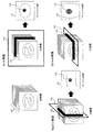
図1は、本発明の医用画像診断装置の一実施の形態の全体構成を示す図である。この装置は、MRI装置、X線CT装置などの撮像部10と、撮像装置から送られる画像データを入力し、画像処理する画像処理部20と、画像処理部が作成した画像を表示するとともに操作者への操作手段を提供するGUIを表示する表示部30と、撮像部10や画像処理部20の動作に必要なパラメータ(処理条件)や処理結果などを記憶する記憶部40とを備えている。また、手術支援装置として利用される場合には、撮像空間の位置を検出する三次元位置検出装置50が備えられる。
<First embodiment>
FIG. 1 is a diagram showing an overall configuration of an embodiment of a medical image diagnostic apparatus of the present invention. This apparatus inputs an image processing unit 20 such as an MRI apparatus and an X-ray CT apparatus, image data sent from the image capturing apparatus, performs image processing, displays an image created by the image processing unit, and operates the apparatus. A
撮像部10の一例として、MRI装置の全体構成を図2に示す。図示するMRI装置は、被検体15が置かれる撮像空間が開放されたオープン型のMRI装置であり、垂直な静磁場を発生させる上部磁石11と下部磁石12、これら磁石を連結するとともに上部磁石11を支持する支柱13、画像を表示するモニタ14、被検体15を搭載するベッド16、制御部17などを備えている。
As an example of the
このMRI装置には、図示していないが、磁石11、12が発生する静磁場に磁場勾配を与える傾斜磁場発生部、静磁場中の被検体15に核磁気共鳴を生じさせるためのRF送信器、被検体15からの核磁気共鳴信号を受信するRF受信器などが備えられている。制御部17は、ワークステーションで構成され、上述した傾斜磁場発生部、RF送信器、RF受信器などを制御するとともに、受信した核磁気共鳴信号の信号処理や画像再構成演算、画像処理などの処理を行う画像処理部20としての機能も備えている。なお図2に示すMRI装置の各要素のうち、三次元位置検出装置50に関連する要素については、別の実施の形態において詳述することとし、ここではその説明を省略する。
In this MRI apparatus, although not shown, a gradient magnetic field generator for applying a magnetic field gradient to the static magnetic field generated by the
画像処理部20は、主として、表示部30に表示されるGUIを作成するGUI作成部、予め取得した或いは3Dスキャンによって取得されたボリューム画像データ(3D画像データ)を用いた断面像や投影画像を作成する断面像作成部および投影画像作成部、ISCで撮像された画像データから断面像などを作成するISC画像作成部などを備えている。
MRI装置で実行される、撮像モード、画像処理モードなどの動作モードは、表示部30に表示されるGUIを介してユーザーにより選択される。ユーザーによる選択に応じて、所定の撮像や画像処理が行われる。撮像は、例えば3Dスキャンや後述する三次元位置検出器を利用したISC(インタラクティブスキャン)のほか各種パルスシーケンスに従った撮像が含まれる。画像処理は、これら撮像と独立して或いは平行して実行される。
The image processing unit 20 mainly includes a GUI creation unit that creates a GUI displayed on the
Operation modes such as an imaging mode and an image processing mode executed by the MRI apparatus are selected by the user via a GUI displayed on the
本発明の医用画像診断装置は、画像処理部20の機能、特に投影画像作成部の機能に特徴があり、3D画像データ全体から選択された一部の断面画像について投影処理を行う機能(以下、部分投影処理ともいう)を備えている。投影処理に供される断面画像は、予め登録した所定の臓器や領域と関連付けて選択される。投影画像作成部の詳細を図3に示す。投影画像作成部は、被検体の目的部位や組織(ターゲット)の設定を受け付ける目的部位設定部21と、記憶部40に格納されている3D画像データから、目的部位設定部21で設定された目的部位を含むスライス画像または多断面画像を選択する断面画像選択部22と、投影画像を作成するための条件を設定する投影条件設定部23、投影処理部24を有している。これら投影画像作成部を含む画像処理部20の機能は、ワークステーション内に搭載されたプログラムとして実行することが可能である。
The medical image diagnostic apparatus of the present invention is characterized by the function of the image processing unit 20, particularly the function of the projection image creation unit, and performs a projection process on a part of the cross-sectional images selected from the entire 3D image data (hereinafter, referred to as “projection processing”). (Also referred to as partial projection processing). A cross-sectional image to be subjected to the projection process is selected in association with a predetermined organ or region registered in advance. Details of the projection image creation unit are shown in FIG. The projection image creation unit includes a target
被検体の目的部位の設定は、本実施の形態では、予め3D画像データを用いて所定の臓器等のターゲットを登録することにより行なわれる。3D画像データを用いたターゲットの登録は、公知のセグメンテーション技術を採用することができる。具体的には、スライス数nの3D画像データをスライス毎に表示部30に表示し、表示された画像上でスライス毎に目的とするターゲット(その輪郭)を指定することにより、3D画像データ上のターゲットの位置情報が登録される。ターゲットのセグメンテーションは、手術支援技術において、目的とする臓器への経路をシミュレーションする際に、目的とする臓器やカテーテルや術具による接触を回避しようとする臓器を予め登録するために行なわれる。従ってシミュレーションのために既にターゲット情報が登録されている場合には、その情報をそのまま使用することも可能である。目的部位設定部21は、GUIを介してターゲットの登録を受付け、或いは既に登録されているターゲットの位置情報(3D画像データ上の座標)を部分投影に使用する位置情報として設定する。
In the present embodiment, the target site of the subject is set by previously registering a target such as a predetermined organ using 3D image data. A known segmentation technique can be employed for target registration using 3D image data. Specifically, 3D image data of the number of slices n is displayed on the
断面画像選択部22は、目的部位設定部21に設定された位置情報を用いて、3D画像データから投影すべきスライス断面または多断面(MPR:Multi Planar Reconstruction)画像を選択する。MPR画像は、投影方向がスライス方向と異なる場合に、複数のスライス画像を用いて投影方向に垂直な断面の画像に再構成した画像である。断面画像選択部22は、スライス画像又はMPR画像から、登録されたターゲットを含む画像を選択する。例えば、ターゲット全て含む最小の数が選択される。
The cross-sectional
投影条件設定部23には、投影手法のほか、選択されたスライス画像又はMPR画像を投影する際の投影方向や、選択された断面画像以外の断面画像を投影するか否かなどの条件が格納されている。これら条件は、予め所定の条件をデフォルトとして設定していてもよいし、GUIを介してユーザーが任意の条件を設定するようにしてもよい。投影手法としては、光線軌跡法による最大輝度投影法(MIP)、最小輝度投影法(MinIP)、レンダリング法など公知の方法を採用することができる。
In addition to the projection method, the projection
上記画像処理部20の諸機能を実現するためのGUIの一例を図4に示す。図示する例では、表示部30の画面400には、3D画像表示部410、投影画像表示部420、投影条件設定部430、および操作部が表示される。3D画像表示部410には、撮像部10あるいは他の撮像手段によって予め取得された3D画像データの断面画像411〜414が表示される。投影画像表示部420には、3D画像データを投影処理することによって作成された投影画像が表示される。投影条件入力部430は、投影処理の種類(MIP,MinIP、レンダリング)の選択、投影処理すべき断面画像の選択、投影パラメータの設定を行なうためのGUIである。図示する例では、投影条件入力部430には、位置決め画像などの参照画像を表示する参照画像表示部431やパラメータの入力を受け付けるパラメータ入力部432などが表示されている。参照画像の上には、3D画像のスライス画像411〜414に対応するスライスが重畳して表示されるとともに、登録された臓器等のターゲット433が識別可能に表示される。
An example of a GUI for realizing various functions of the image processing unit 20 is shown in FIG. In the illustrated example, a 3D
また画面400の下側は、医用画像診断装置の各動作の開始や終了などの指令を入力するための操作部であり、ここでは、3D画像データを得るための「3DScanボタン」441、インタラクティブスキャンを開始・終了するための「ISC:ON/OFFボタン」442、投影断面の表示方法を切替えるための「断面情報切換えボタン」443、投影画像作成のための「投影画像作成ボタン」444、3D画像を用いたナビゲーションを開始・終了するための「3Dナビゲーション:ON/OFFボタン」445、3D画像を構成する複数の断面画像を複数のブロックに分割した場合における表示ブロックを選択するための「表示ブロック選択ボタン」446が表示される。
The lower part of the
次に、本実施の形態における医用画像診断装置の動作の一例を、図4及び図5を参照して説明する。図5は動作の手順を示すフローである。 Next, an example of the operation of the medical image diagnostic apparatus according to the present embodiment will be described with reference to FIGS. FIG. 5 is a flowchart showing an operation procedure.
まず目的部位設定部21が、注目している臓器や組織であるターゲットの登録を受け付け、ターゲットの位置情報を登録する(ステップ501)。ターゲットの登録は、例えば、図4の画面の3D画像表示部410に表示される各断面画像411〜414上でターゲットとなる臓器をマウスなどの入力装置で指定することにより行なわれる。次に投影条件入力部430を介して入力される投影処理の条件やパラメータを設定する(ステップ502)。例えば、投影処理の種類、3D画像データの分割数や投影面などが設定される。これらの条件やパラメータは予め所定のものをデフォルトとして設定しておき、ユーザーが変更するようにしてもよい。例えば、投影面は、デフォルトとしてAxial面、Sagital面およびCoronal面が設定される。投影条件が設定され、投影画像作成ボタン444が操作されると、その投影条件に従い部分投影処理を開始し、得られた投影画像を投影画像表示部420に表示する(ステップ503)。図4に示す例では、3D画像データは、ターゲット433を含むブロック422と、その前後のブロック421、423に分割して投影処理がなされ、それぞれのブロックについてAxial面、Sagital面およびCoronal面の投影画像が表示されている。
First, the target
その後、投影処理条件の変更がなければ処理を終了する。投影処理の変更がある場合には、再度、投影条件入力部430を介して投影処理のパラメータを受付け、投影画像作成ボタン444の操作により、新たな条件で投影画像の作成、表示が行なわれる処理を開始し、得られた投影画像を投影画像表示部420に表示する(ステップ504)。投影条件を異ならせた投影処理の具体例を図6〜図9に示す。ここでは投影処理がMIPである場合を例にして説明する。
Thereafter, if there is no change in the projection processing conditions, the processing is terminated. If there is a change in the projection processing, the projection processing parameters are received again via the projection
図6に示す例では、上述したように3D画像データ600(601〜605)から、ターゲット615を含むスライス602〜604を選択し、それらスライス断面からMIP画像(パーシャルMIP)610を作成する。
In the example shown in FIG. 6, the
図7に示す例は、3D画像データ700から3方向の投影画像を生成する例を示している。この場合、スライス選択部22は、投影条件設定部23に設定されている3つの投影方向について、ターゲットを含むスライス画像およびMPR画像を選択する。図示する例では、Axial断面710についてターゲットを含むスライス画像701が選択されており、Sagital断面720およびCoronal断面730のそれぞれについて、MPR画像702、703が作成され、選択されている。これらスライス画像701およびMPR画像702、703に対し、それぞれ相当する投影方向のMIP投影画像711、721、731を作成する。これにより、Axial断面、Sagital断面およびCoronal断面において、各MIP画像711、721、731上にターゲット715が明瞭に描出される。
The example illustrated in FIG. 7 illustrates an example in which a projection image in three directions is generated from the
図8に示す例では、ターゲットを含む断面画像の投影画像のみならず、その前後の断面画像についても投影画像を作成する。この場合、断面画像選択部22が、ターゲットを含む断面画像を選択することは、図6に示す例と同じであるが、3D画像データ800を選択されたブロック802と、選択ブロック802に対し両側に位置する断面画像からなるブロック801、803に分け、投影処理部24は、各ブロックの投影処理を行ない、3つのMIP画像811、812、813を表示する。この場合にも、1つの投影方向だけでなく、例えば3軸方向に投影処理を行い、各ブロックについて3軸方向のMIP画像811〜813、821〜823、831〜833を表示することも可能である。このように選択ブロックの前後のブロックについても投影画像を表示することにより、ターゲットと他の臓器や組織との奥行き方向(投影方向)の位置関係が把握しやすくなる。
In the example illustrated in FIG. 8, not only the projection image of the cross-sectional image including the target but also the projection images are generated for the cross-sectional images before and after the target. In this case, it is the same as the example shown in FIG. 6 that the cross-sectional
図9に示す例は、図8に示す例の応用例であり、断面画像選択部22が、ターゲットを含む断面画像(選択ブロック901)を選択するとともに、そのブロック901と前後のブロック902、903について投影処理を行なうことは、図8に示す例と同じであるが、3D画像データの分割方法を一部手動にしたものである。具体的には、前後のブロック902、903については、一部、選択ブロック901とオーバーラップするようにブロックの大きさを可変にする。図示する例では、選択ブロック901はターゲットを含むスライス画像、ブロック902はターゲットを含めたおおよそ上半分のスライス画像、ブロック903はターゲットの末端を含めた下側のスライス画像であり、それぞれMIP画像911、912、913が作成される。選択ブロック901から作成したターゲット915を含めたMIP画像911では、ターゲット以外にそれほど多くの情報が表示されることはなくターゲット915が明瞭に表示され、ブロック902から作成したMIP画像912ではターゲット以外の情報をあえて混在させて、他の臓器との関係を把握できるようにしている。またブロック903から作成したMIP画像913は、ターゲット915の情報を最小限にしてその他の情報を表示している。この場合にも、1つの投影方向だけでなく、例えば3軸方向に投影処理を行い、各ブロックについて3軸方向のMIP画像を表示することも可能である。
The example shown in FIG. 9 is an application example of the example shown in FIG. 8, and the cross-sectional
以上、図6〜図9を参照して、第一の実施の形態における投影処理の具体例を説明したが、これらは投影処理の単なる例示であり、投影処理条件は種々の変更が可能である。例えば、上記具体例では、選択ブロックに対しては単一の投影処理を行なうこととしているが、例えばターゲットが大きなボリュームを持つ場合には、ブロック内を更に分割して投影処理することも可能であるし、選択ブロック以外に投影処理するブロックについて、ブロックのサイズ即ちブロックを構成する断面画像数に制限を設けることも可能である。 The specific examples of the projection processing in the first embodiment have been described above with reference to FIGS. 6 to 9. However, these are merely examples of the projection processing, and the projection processing conditions can be variously changed. . For example, in the above specific example, a single projection process is performed on the selected block. However, for example, when the target has a large volume, the block can be further divided and projected. In addition to the selected block, it is possible to limit the size of the block, that is, the number of cross-sectional images constituting the block, for the block to be projected.
本実施の形態によれば、予め登録したターゲットの位置情報を用いて、投影処理する断面画像を選択し、選択された断面について投影処理を行なうようにしたので、確実に目的とする臓器や領域を含み且つ不要な情報の混入を極力少なくした投影画像を速やかに得ることができる。またMRI装置が、予めターゲットの登録情報を持つ場合には、それを利用して確実且つ速やかな投影処理を行なうことができる。 According to the present embodiment, since the cross-sectional image to be projected is selected using the position information of the target registered in advance and the projection processing is performed on the selected cross-section, the target organ or region is surely obtained. In addition, it is possible to promptly obtain a projection image that contains a minimal amount of unnecessary information. When the MRI apparatus has target registration information in advance, it can be used to perform reliable and prompt projection processing.
なお以上説明した実施の形態では、MRI装置に組み込まれた画像処理部の機能として本発明を説明したが、画像処理部はMRI装置やX線CT装置などの撮像装置とは独立した装置として、例えば医用撮像装置から転送される3D画像を処理する画像処理装置として実現することも可能である。 In the embodiment described above, the present invention has been described as a function of the image processing unit incorporated in the MRI apparatus. However, the image processing unit is an apparatus independent of an imaging apparatus such as an MRI apparatus or an X-ray CT apparatus. For example, it can be realized as an image processing apparatus that processes a 3D image transferred from a medical imaging apparatus.
<第二の実施の形態>
本実施の形態の医用画像診断装置は、第一の実施の形態の医用画像診断装置とは、撮像部10が手術支援装置の一部であり、必須の構成要素として、撮像空間(実空間)の位置を検出する三次元位置検出装置50を備えている点を除き、図1及び図2に示す医用画像診断装置と同様である。以下、第一の実施の形態の医用画像診断装置に付加された要素(三次元位置検出装置50に関する要素)について、図2を参照して説明する。
<Second Embodiment>
The medical image diagnostic apparatus according to the present embodiment is different from the medical image diagnostic apparatus according to the first embodiment in that the
本実施の形態のMRI装置は、医者などの操作者18が扱う術具19の位置を検出するための三次元位置検出手段として、位置検出デバイス51、基準ツール52、パーソナルコンピュータ53などを備えている。位置検出デバイス51は、2台の赤外線カメラ511と、赤外線を発光する図示しない発光ダイオードを備え、断層面指示デバイスであるポインタ54の位置及び姿勢を検出する。基準ツール52は、赤外線カメラ511の座標系とMRI装置1の座標系をリンクさせるもので、3つの反射球521を備え、上部磁石11の側面に設けられている。ポインタ54は、術具19に固定されている。ポインタ54には、基準ツール52と同様に3つの反射球が固定されており、これら3つの反射球の位置を検出することにより、これら反射球と所定の関係にある術具先端の位置と術具の向き(方向)とを特定することができる。なお、位置検出デバイス51は、アーム111により移動可能に上部磁石11に連結され、MRI装置10に対する配置を適宜変更することができる。
The MRI apparatus according to the present embodiment includes a
パーソナルコンピュータ53には、赤外線カメラ511が検出し算出したポインタ54の位置或いは術具の位置と方向が、位置データとして、例えば、RS232Cケーブル55を介して送信される。パーソナルコンピュータ53は、制御部17と接続されており、赤外線カメラ53が検出し算出した位置情報をMRI装置10で利用可能な位置データに変換し制御部17へ送信する。
The position of the
位置データは、MRI装置がISCモードで動作しているときは、撮像シーケンスの撮像断面へ反映される。新たな撮像断面で取得された画像は液晶モニタ14に表示される。例えば断層面指示デバイスであるポインタ54を穿刺針などにとりつけ、穿刺針のある位置を常に撮像断面とするように構成した場合、モニタには針を常に含む断面が表示されることになる。MRI装置が画像処理モード(投影処理モード)で動作しているときは、位置検出手段からの位置データは、断面図作成、投影処理、特に部分的な投影処理を行なうための位置情報として使用される。
The position data is reflected in the imaging section of the imaging sequence when the MRI apparatus is operating in the ISC mode. An image acquired with a new imaging section is displayed on the
MRI装置で実行される、撮像モード、画像処理モードなどの動作モードは、ワークステーションに備えられた入出力装置(表示部)のGUIを介してユーザーにより選択される。ユーザーによる選択に応じて、所定の撮像や画像処理が行われる。撮像は、例えば3Dスキャンや三次元位置検出器50を利用したISC(インタラクティブスキャン)のほか各種パルスシーケンスに従った撮像が含まれる。また画像処理は、予め取得した或いは3Dスキャンによって取得されたボリューム画像データ(3D画像データ)を用いた断面像作成、投影画像作成、ISCで撮像された断面像作成などを含み、撮像と独立して或いは平行して実行される。
Operation modes such as an imaging mode and an image processing mode executed by the MRI apparatus are selected by a user via a GUI of an input / output device (display unit) provided in the workstation. Predetermined imaging and image processing are performed according to the selection by the user. Imaging includes, for example, imaging according to various pulse sequences in addition to ISC (interactive scanning) using a 3D scan or a three-
画像処理部20における投影画像作成部の構成は、図3に示す投影画像作成部と同様であり、被検体の目的部位の設定を受け付ける目的部位設定部21と、記憶部40に格納されている3D画像データから、目的部位設定部21で設定された目的部位を含むスライス画像または多断面画像を選択する断面画像選択部22と、投影画像を作成するための条件を設定する投影条件設定部23、投影処理部24を有している。
The configuration of the projection image creation unit in the image processing unit 20 is the same as that of the projection image creation unit shown in FIG. 3, and is stored in the target
ただし本実施の形態では、目的部位設定部21は、予め登録されたターゲットの位置情報を用いるのではなく、ポインタ54で指示された位置データを投影処理を行なう際の位置情報として設定する。また投影条件設定部23は、GUIを介して入力される条件のほかに、必要に応じて、ポインタ54で指示された方向を投影方向として設定する。投影条件設定に際し、表示部30に表示されるGUIは図4に示したものと同様であり、ユーザーは投影条件入力部430を介して、投影処理の種類や投影面、3D画像の分割数やブロックの選択を行なうことが可能である。
However, in the present embodiment, the target
以下、上記構成の医用画像診断装置の動作の一例を、図10に示すフローおよび図4に示すGUI例を参照して説明する。 Hereinafter, an example of the operation of the medical image diagnostic apparatus having the above configuration will be described with reference to the flow shown in FIG. 10 and the GUI example shown in FIG.
まず図4に示す画面400に表示された3DSanボタン441を選択して、撮像部10を撮像モードで動作させて3D撮像を行い、3D画像データを取得する(ステップ101)。3D撮像法は、撮像部10として用いるモダリティに応じて適切な撮像方法が選ばれる。3D画像データは、その後のナビゲーション機能や投影処理のために使用される。なお3D画像データとして、他のモダリティで撮像した3D画像データを格納しており、それを用いる場合には、撮像部10の撮像ステップ101は必須ではない。
First, the
次いで、投影処理(図ではMIP処理)に必要なパラメータの設定を受け付ける(ステップ102)。投影処理のパラメータとは、投影処理の条件であり、具体的には、3D画像データをブロックに分割する場合の分割数、分割方法(等分割/任意)である。表示部30には、図4に示したように、ユーザーがパラメータの設定を行なうための入力画面430が表示される。この画面には、例えば、ターゲット433を含む参照画像431に重畳して、3D画像データを取得した撮像領域の各スライス411〜414がとともに表示される。ユーザーは、入力画面430に数値入力やボタン選択などの操作を行なうことにより、参照画像表示部431に表示されたスライスの分割数や分割する場合のブロックのボリュームなどを設定することができる。なお図4には示していないが、投影処理の方向なども選択することが可能である。デフォルトとしてスライス方向を投影処理として設定しておいてもよい。
Next, the setting of parameters necessary for the projection process (MIP process in the figure) is accepted (step 102). The parameters of the projection processing are conditions for the projection processing, and specifically, the number of divisions and the division method (equal division / arbitrary) when 3D image data is divided into blocks. The
投影処理のためのパラメータが設定され、投影処理ボタン444が選択されると、ステップ102で設定された条件で投影処理が行われ、作成されたMIP画像が投影画像表示部420に表示される(ステップ103)。必要であれば、投影処理のパラメータを変更して、別なMIP画像を作成し、表示させる(ステップ104)。
When parameters for projection processing are set and the
ユーザーは、表示部30に表示された投影画像を指標として手術を開始し(ステップ106)、各種ナビゲーション機能を併用して手術を行なう(ステップ107)。各種ナビゲーションには、例えば、術具で必要な位置を指し示し、3D画像データから、その位置を含む三断面図を作成し、表示させる3Dナビゲーションや、内視鏡などを併用している場合には、その映像の表示を含む。本実施の形態では、さらにナビゲーション機能の一つとして投影処理を含む。即ち術具が指し示す位置を検出し(ステップ108)、術具の方向と設定されたパラメータに基き投影処理を行い、作成したMIP画像を投影画像表示部420に表示する(ステップ109)。例えば、パラメータとして、分割数3とAxial、SagitalおよびCoronalの3つの投影面(投影方向)が設定され、3D画像データが所定のブロックα1、α2、α3に分割されている場合には、これらブロックの各投影面の画像が投影画像表示部420に表示される。図4に示す例では、中央に表示されるブロックにターゲット433が他の情報に紛れることなく明瞭に表示されている。必要に応じて、パラメータを設定しなおし(ステップ110、111)、新たな条件でMIP処理を行い、MIP画像を作成、表示する。
The user starts an operation using the projection image displayed on the
また、これら表示画像に術具の位置を示す情報、例えば仮想術具の画像を重畳して表示することも可能である(ステップ112)。術具位置は、既に述べたように三次元位置検出器によってその位置が検出され、画像空間の位置情報として得られているので、仮想術具の画像をその位置に配置することによって表示が可能となる。
3D画像データが所定のブロックα1、α2、α3に分割されている場合には、表示ブロック選択ボタンを操作して、所望のブロックを選択することにより、選択されたブロックの投影画像、例えば3方向の投影画像を表示させることも可能である(ステップ113)。
In addition, information indicating the position of the surgical instrument, for example, an image of a virtual surgical instrument, can be displayed superimposed on these display images (step 112). As described above, the position of the surgical instrument is detected by the three-dimensional position detector and obtained as position information in the image space, and can be displayed by placing the virtual instrument image at that position. It becomes.
When the 3D image data is divided into predetermined blocks α1, α2, and α3, by operating the display block selection button and selecting a desired block, a projected image of the selected block, for example, three directions It is also possible to display the projected image (step 113).
さらに投影画像の表示は、装置座標の3つの軸を基準として、例えば、Axial断面であれば、z軸を垂直方向、x軸を水平方向に表示し、Sagital断面であれば、z軸を垂直方向、y軸を水平方向に表示し、Coronal断面であれば、y軸を垂直方向、x軸を水平方向に表示することも可能であるし、術具の方向を基準として、例えば、Axial断面とCoronal断面では、術具の方向が水平方向となるように表示し、Sagital断面では術具方向が画面と直交するように表示を変更することも可能である。このような表示の変更は、GUIの「断面情報切換えボタン」443を操作することにより実行される。上記処理108〜113は、終了の指示があるまで続けられる(ステップ114)
Furthermore, the projected image is displayed based on the three axes of the apparatus coordinates, for example, if the Axial section is displayed, the z-axis is displayed in the vertical direction, the x-axis is displayed in the horizontal direction, and if it is the Sagittal section, the z-axis is displayed vertically. If the direction and the y-axis are displayed in the horizontal direction and the coronal section is displayed, the y-axis can be displayed in the vertical direction and the x-axis can be displayed in the horizontal direction. For example, the axial section can be displayed based on the direction of the surgical instrument. It is also possible to change the display so that the direction of the surgical instrument is the horizontal direction in the Coronal section and the direction of the surgical instrument is orthogonal to the screen in the Sagittal section. Such a display change is executed by operating a “section information switching button” 443 on the GUI. The above-described
投影条件を異ならせた投影処理の具体例を図11〜図14に示す。ここでは投影処理がMIPである場合を例にして説明する。 Specific examples of the projection process with different projection conditions are shown in FIGS. Here, a case where the projection processing is MIP will be described as an example.
図11に示す例は、ターゲット1105を含む3Dボリューム画像1100に対して、ポインタ54を取り付けた術具19の方向に応じて投影処理を行い投影画像1101〜1103を作成している。図示する例では、3Dボリューム画像1100全体について投影処理を行っているが、例えば、術具先端位置から術具方向前方にある断面の一部あるいは全部を選択して投影処理することも可能である。このような処理条件は、図10に示すステップ102あるいはステップ111で設定することができる。
なお投影処理機能とともに術具追随撮像機能(ISC)が選択されている場合には、上記投影処理と並行して術具位置に対応した撮像が行われ、画面には、術具方向に応じた投影画像の表示とともに、ISC画像が表示される。
In the example illustrated in FIG. 11, projection processing is performed on the
When the surgical instrument following imaging function (ISC) is selected together with the projection processing function, imaging corresponding to the surgical instrument position is performed in parallel with the projection process, and the screen corresponds to the surgical instrument direction. An ISC image is displayed together with the projection image.
図12に示す例は、ターゲット1205を含む3Dボリューム画像1200から、ポインタ54を取り付けた術具19の術具方向に応じて3つの断面の画像データ1201〜1203が選択され、選択された画像データ1201〜1203をそれぞれ投影処理し投影画像1211〜1213を作成している。この例では、3つの断面は、ターゲット1205および術具19を含み、ターゲット1205を含み術具方向に直交する断面、術具方向に直交する断面(第一直交面)、ターゲット1205および術具19を含み、第一直交面に直交する断面(第二直交面)である。
In the example shown in FIG. 12, three
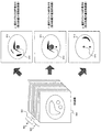
図13に示す例は、同図(a)に示すように、予め3Dボリューム画像データ1300を複数(図では3つ)のブロック1301〜1303に分割しておき、術具の位置と方向に応じて、ブロック1301〜1303のいずれかを自動的に選択し、投影処理を行う。例えば、図10に示すステップ102で、投影処理パラメータとして3Dボリューム画像データの分割数が3に設定されており、投影処理ステップ103では、図13(b)に示すように、各ブロックから、ブロックを構成する断面と平行な面を投影面とする投影画像1311〜1313が作成される。図中、1305は登録されているターゲットを示す。
In the example shown in FIG. 13, as shown in FIG. 13A, the 3D volume image data 1300 is divided into a plurality of (three in the figure) blocks 1301 to 1303 in accordance with the position and direction of the surgical instrument. Thus, any one of the
手術が開始され、例えば、ISC機能が作動し、ステップ108で術具位置が検出されると、術具位置があるブロックが自動的に選択されて、選択されたブロックの投影画像が作成される。この投影処理の投影方向は、例えば、術具方向と平行な面が投影面となるように選択される。例えば術具19が上半身にある場合は、術具位置から、ISC撮像断面として、術具を含み術具方向と平行な撮像断面1321が定義され、ISC撮像が行われるとともに、術具があるブロック1301を使用して撮像断面1321と平行なMIP画像1341が作成される。腹部に術具がある場合には、ISCの撮像断面1322が定義されるとともに、ブロック1302を使用して、MIP画像1342が作成される。また、下半身に術具がある場合には、ISCの撮像断面1323が定義されるとともに、ブロック1303を使用して、MIP画像1343が作成される。
When surgery is started, for example, when the ISC function is activated and the position of the surgical instrument is detected in
このように、術具位置に応じて投影処理されるブロックが選択され、術具位置および方向で決まるISC断面にあわせて投影処理面が決定される。
なお投影処理をISC撮像と併用する場合を説明したが、投影処理はISCと独立して行うことも可能であり、この場合にも、位置検出装置50が検出した術具位置をもとにブロックが選択され、術具方向に応じて投影面を決定することができる。あるいは、術具位置に関わらず、ユーザーが表示ブロック選択ボタンを操作することによって、部位に応じてブロックを選択し、予め設定された1ないし複数の投影方向に投影処理し、投影画像を表示させることも可能である。
In this way, the block to be projected is selected according to the surgical instrument position, and the projection processing surface is determined in accordance with the ISC cross section determined by the surgical instrument position and direction.
Although the case where the projection processing is used together with the ISC imaging has been described, the projection processing can also be performed independently of the ISC. In this case as well, the block is based on the surgical instrument position detected by the
また本発明の投影処理を、3Dナビゲーションと並行して行うことも可能である。この場合には、3Dナビゲーションの3断面図を作成するために術具19で指示した位置をもとに、3Dボリューム画像データから投影処理すべき断面画像が選択され、投影処理が行われる。投影処理は、術具方向を含む一方向のみについて行ってもよいし、それと直交する1ないし複数の方向について行ってもよく、投影方向に応じて選択する断面画像(スライス画像またはMPR画像)が作成、選択される。この点は第一の実施の形態と同様である。
Further, the projection processing of the present invention can be performed in parallel with 3D navigation. In this case, a cross-sectional image to be projected is selected from the 3D volume image data based on the position designated by the
本実施の形態による医用画像診断装置を手術支援に適用した場合の表示画面例を図14〜図16に示す。これらは表示の一例であり、表示画面は処理に応じて異なるものであり、また画面の配置や形態なども限定されるものではない。 Examples of display screens when the medical image diagnostic apparatus according to the present embodiment is applied to surgical support are shown in FIGS. These are examples of display, the display screen differs depending on the process, and the arrangement and form of the screen are not limited.
図14〜図16において、左側の画面は3Dナビゲーション画像表示部1510、右側の画面はISCおよび投影画像表示部1520であり、本発明による投影画像は、図示する例では、ISCおよび投影画像表示部1520に表示される。3Dナビゲーション画像表示部1510は、図14〜図16ともに同様であり、術具19が指示した位置を含む3つの断面画像(Axial断面図、Sagital断面図、Coronal断面図)1511〜1513とボリュームレンダリング画像1514が、それぞれ仮想術具1515とともに表示されている。図中、登録されたターゲットは符号1505で示している。
14 to 16, the left screen is a 3D navigation
図14に示す投影処理の画面は、図12に示す投影処理に対応しており、ISCおよび投影画像表示部1520には、ISCにより撮像された術具19を含む断面画像1521とともに、3分割したブロックのうち術具がある一つのブロックについて、術具位置を含む3つの投影面の投影画像(術具に平行な面1531、術具に直交する面(第一直交面)1532、面1531と面1532に直交する面(第二直交面)1533)が、それぞれ仮想術具1515およびターゲット1505とともに表示されている。
The projection processing screen shown in FIG. 14 corresponds to the projection processing shown in FIG. 12, and the ISC and projection
図14に示す投影画像が、仮想術具1515の方向を基準に作成されているのに対し、図15に示す投影画像は、装置座標の3軸を基準に作成されている点が異なる。すなわち、この例では、術具位置を含むAxial断面図、Sagital断面図、Coronal断面図の3つの投影画像が作成され、表示されている。
図16に示す例では、ISC画像ではなく、部分的な投影処理画像と併せて通常のMIP画像、すなわち3D画像データを分割せずに全体として投影処理した画像が仮想術具1515およびターゲット1505とともに表示されている。
The projection image shown in FIG. 14 is created based on the direction of the virtual
In the example shown in FIG. 16, not an ISC image but a normal MIP image combined with a partial projection processed image, that is, an image obtained by performing projection processing as a whole without dividing 3D image data together with a virtual
本実施の形態によれば、手術支援機能を有する医用画像診断装置において、既存の機能を利用して任意の領域に対する部分的な投影処理が可能であり、手術に必要な画像情報提示と治療に必要なガイディング機能の両立が可能となる。また部分的な投影処理の領域や投影条件を手術の進行や状況に応じて変更することが可能であり、手術支援機能をさらに高めることができる。 According to the present embodiment, in a medical image diagnostic apparatus having a surgery support function, it is possible to perform a partial projection process on an arbitrary region using an existing function, and for image information presentation and treatment necessary for surgery. It is possible to achieve both necessary guiding functions. In addition, it is possible to change the partial projection processing area and projection conditions according to the progress and situation of the operation, and the operation support function can be further enhanced.
本発明によれば、診断に必要とされる部分のみを取り出して部分的な投影処理を行うことができるので、必要な生体情報が他の情報に紛れることなく正確な診断に資することができる。また既にある手術支援機能を利用して、任意の投影処理領域をリアルタイムで指定し、投影画像表示することができるので、高い手術支援機能を持つ医用画像診断装置を提供できる。 According to the present invention, only a portion required for diagnosis can be taken out and a partial projection process can be performed, so that necessary biological information can be contributed to an accurate diagnosis without being mixed with other information. In addition, since an arbitrary projection processing region can be designated in real time and a projected image can be displayed using an existing operation support function, a medical image diagnostic apparatus having a high operation support function can be provided.
10・・・撮像部、20・・・画像処理部、21・・・目的部位設定部、22・・・断面画像選択部、23・・・投影条件設定部、24・・・投影処理部、30・・・表示部、40・・・記憶部、50・・・三次元位置検出装置。
DESCRIPTION OF
Claims (12)
前記画像処理手段は、前記被検体の目的部位の設定を受け付ける目的部位設定手段と、前記三次元画像データから前記目的部位設定手段で設定された目的部位に関連する複数の断面画像を選択する断面画像選択手段と、前記断面画像選択手段で選択された複数の断面画像を用いて投影画像を作成する投影処理部とを備えたことを特徴とする医用画像診断装置。 In a medical image diagnostic apparatus comprising an imaging means for imaging a subject and obtaining three-dimensional image data, and an image processing means for creating a two-dimensional image using the three-dimensional image data,
The image processing means is a target part setting means for receiving setting of a target part of the subject, and a cross section for selecting a plurality of cross-sectional images related to the target part set by the target part setting means from the three-dimensional image data. A medical image diagnostic apparatus comprising: an image selection unit; and a projection processing unit that creates a projection image using a plurality of cross-sectional images selected by the cross-sectional image selection unit.
前記画像処理手段は、前記投影画像を作成するための条件を設定する投影条件設定手段を備え、前記投影処理部は、前記投影条件設定手段に設定された条件に基き前記投影画像を作成することを特徴とする医用画像診断装置。 The medical image diagnostic apparatus according to claim 1, wherein the image processing unit includes a projection condition setting unit that sets a condition for creating the projection image, and the projection processing unit includes the projection condition setting unit. A medical image diagnostic apparatus, wherein the projection image is created based on a set condition.
前記投影画像を作成するための条件は、投影方向を含み、前記断面画像選択手段は前記投影条件設定手段に設定された投影方向に直交する断面の断面画像を選択することを特徴とする医用画像診断装置。 The medical diagnostic imaging apparatus according to claim 2,
The condition for creating the projection image includes a projection direction, and the cross-sectional image selection unit selects a cross-sectional image of a cross section orthogonal to the projection direction set in the projection condition setting unit. Diagnostic device.
前記投影画像を作成するための条件は、前記三次元画像データを複数のブロックに分割する分割方法を含み、前記投影処理手段は、前記投影条件設定手段に設定された分割方法に従って分割された各ブロックの断面画像を、個別に或いは組み合わせて投影処理することを特徴とする医用画像診断装置。 The medical diagnostic imaging apparatus according to claim 2,
The condition for creating the projection image includes a division method for dividing the three-dimensional image data into a plurality of blocks, and the projection processing unit is configured to perform each division performed according to the division method set in the projection condition setting unit. A medical image diagnostic apparatus characterized by projecting a sectional image of a block individually or in combination.
前記被検体の実空間における所定の位置を指示する位置指示手段と、前記位置指示手段が指示する位置を検出する位置検出手段とを備え、
前記目的部位設定手段は、前記位置検出手段が検出した位置に基き、前記目的部位を設定することを特徴とする医用画像診断装置。 The medical image diagnostic apparatus according to claim 1,
Position indicating means for indicating a predetermined position in the real space of the subject, and position detecting means for detecting a position indicated by the position indicating means,
The medical image diagnostic apparatus, wherein the target part setting unit sets the target part based on the position detected by the position detection unit.
前記画像処理手段は、前記位置検出手段で検出された前記位置指示手段の位置および方向に基き、リアルタイムで、前記三次元画像データから前記検出された方向を投影方向とする投影画像を作成することを特徴とする医用画像診断装置。 An imaging means for imaging a subject, an image processing means for creating one or a plurality of two-dimensional images using previously acquired three-dimensional image data of the subject, and a predetermined position in the real space of the subject are indicated Position indicating means, position detecting means for detecting a position and direction indicated by the position indicating means, a subject image captured by the imaging means, and a two-dimensional image created by the image processing means from the three-dimensional image data In a medical image diagnostic apparatus comprising display means for displaying
The image processing means creates a projection image having the detected direction as the projection direction from the three-dimensional image data in real time based on the position and direction of the position indicating means detected by the position detecting means. A medical image diagnostic apparatus characterized by the above.
前記画像処理手段は、前記被検体の目的部位の設定を受け付ける目的部位設定手段と、前記三次元画像データから前記目的部位設定手段で設定された目的部位に関連する複数の断面画像を選択する断面画像選択手段と、前記断面画像選択手段で選択された複数の断面画像を用いて投影画像を作成する投影処理部とを備え、
前記目的部位設定手段は、前記位置検出手段が検出した位置に基き、前記目的部位を設定することを特徴とする医用画像診断装置。 The medical image diagnostic apparatus according to claim 6,
The image processing means is a target part setting means for receiving setting of a target part of the subject, and a cross section for selecting a plurality of cross-sectional images related to the target part set by the target part setting means from the three-dimensional image data. An image selection unit, and a projection processing unit that creates a projection image using a plurality of cross-sectional images selected by the cross-sectional image selection unit,
The medical image diagnostic apparatus, wherein the target part setting unit sets the target part based on the position detected by the position detection unit.
前記画像処理手段は、前記投影画像の作成と並行して、前記三次元画像データから、前記検出された位置で特定される点を含む断面図を作成することを特徴とする医用画像診断装置。 The medical diagnostic imaging apparatus according to claim 6 or 7,
The medical image diagnostic apparatus, wherein the image processing unit creates a cross-sectional view including a point specified at the detected position from the three-dimensional image data in parallel with the creation of the projection image.
前記撮像手段は、前記画像処理手段による前記投影画像の作成と並行して、前記検出された位置で特定される点を含み、前記検出された方向で決定される被検体断面を撮像することを特徴とする医用画像診断装置。 The medical diagnostic imaging apparatus according to claim 6 or 7,
In parallel with the creation of the projection image by the image processing unit, the imaging unit includes a point specified at the detected position, and images a cross section of the subject determined in the detected direction. A medical image diagnostic apparatus as a feature.
前記画像処理手段が行う投影処理は、最大値投影、最小値投影、レンダリングの少なくともいずれか1つであることを特徴とする医用画像診断装置。 The medical image diagnostic apparatus according to any one of claims 1 to 9,
The medical image diagnosis apparatus according to claim 1, wherein the projection processing performed by the image processing means is at least one of maximum value projection, minimum value projection, and rendering.
前記撮像手段は、MRI装置、X線CT装置、超音波診断装置、PET装置のいずれかであることを特徴とする医用画像診断装置。 The medical image diagnostic apparatus according to any one of claims 1 to 10,
The medical imaging diagnostic apparatus characterized in that the imaging means is any one of an MRI apparatus, an X-ray CT apparatus, an ultrasonic diagnostic apparatus, and a PET apparatus.
前記被検体の目的部位の設定を受け付ける目的部位設定手段と、前記三次元画像データから前記目的部位設定手段で設定された目的部位を含む断面画像を選択する断面画像選択手段とを備え、前記断面画像選択手段で選択されたスライス画像について投影画像を作成することを特徴とする画像処理装置。 An image processing apparatus that performs image processing on three-dimensional image data of a subject imaged by a medical image diagnostic apparatus and creates a projection image of a desired position and direction of the subject,
A target site setting unit that receives setting of a target site of the subject; and a cross-sectional image selection unit that selects a cross-sectional image including the target site set by the target site setting unit from the three-dimensional image data; An image processing apparatus that creates a projection image for a slice image selected by an image selection means.
Priority Applications (1)
| Application Number | Priority Date | Filing Date | Title |
|---|---|---|---|
| JP2008053526A JP5417609B2 (en) | 2008-03-04 | 2008-03-04 | Medical diagnostic imaging equipment |
Applications Claiming Priority (1)
| Application Number | Priority Date | Filing Date | Title |
|---|---|---|---|
| JP2008053526A JP5417609B2 (en) | 2008-03-04 | 2008-03-04 | Medical diagnostic imaging equipment |
Publications (2)
| Publication Number | Publication Date |
|---|---|
| JP2009207677A true JP2009207677A (en) | 2009-09-17 |
| JP5417609B2 JP5417609B2 (en) | 2014-02-19 |
Family
ID=41181422
Family Applications (1)
| Application Number | Title | Priority Date | Filing Date |
|---|---|---|---|
| JP2008053526A Active JP5417609B2 (en) | 2008-03-04 | 2008-03-04 | Medical diagnostic imaging equipment |
Country Status (1)
| Country | Link |
|---|---|
| JP (1) | JP5417609B2 (en) |
Cited By (16)
| Publication number | Priority date | Publication date | Assignee | Title |
|---|---|---|---|---|
| WO2011055741A1 (en) * | 2009-11-06 | 2011-05-12 | 株式会社 日立メディコ | X-ray ct device, and x-ray ct imaging method |
| JP2011139788A (en) * | 2010-01-07 | 2011-07-21 | Hitachi Medical Corp | Image processor |
| JP2012081167A (en) * | 2010-10-14 | 2012-04-26 | Hitachi Medical Corp | Medical image display device and medical image guidance method |
| WO2012132302A1 (en) * | 2011-03-29 | 2012-10-04 | 富士フイルム株式会社 | Photoacoustic imaging method and device |
| JP2013521971A (en) * | 2010-03-24 | 2013-06-13 | シンバイオニクス リミテッド | System and method for computerized simulation of medical procedures |
| JP2014069075A (en) * | 2012-09-29 | 2014-04-21 | Qinghua Univ | Device and method for localize object in ct image formation |
| JP2015002844A (en) * | 2013-06-20 | 2015-01-08 | 株式会社東芝 | X-ray ct apparatus |
| JP2017080158A (en) * | 2015-10-29 | 2017-05-18 | キヤノン株式会社 | Image processing apparatus, image processing method, and program |
| JP2017174039A (en) * | 2016-03-23 | 2017-09-28 | 富士フイルム株式会社 | Image classification device, method, and program |
| KR101790436B1 (en) * | 2016-04-15 | 2017-10-26 | 이화여자대학교 산학협력단 | Method and apparatus for processing medical image |
| US20180085175A1 (en) * | 2015-08-19 | 2018-03-29 | Brainlab Ag | Determining a configuration of a medical robotic arm |
| JP2019146788A (en) * | 2018-02-27 | 2019-09-05 | キヤノンメディカルシステムズ株式会社 | Magnetic resonance imaging apparatus |
| JP2019146789A (en) * | 2018-02-27 | 2019-09-05 | キヤノンメディカルシステムズ株式会社 | Magnetic resonance imaging apparatus |
| WO2020122357A1 (en) * | 2018-12-11 | 2020-06-18 | 메디컬아이피 주식회사 | Method and device for reconstructing medical image |
| JP2021526270A (en) * | 2018-09-21 | 2021-09-30 | ▲蘇▼州瑞派▲寧▼科技有限公司Raycan Technology Co., Ltd. | Medical image four-dimensional visualization method and equipment |
| US11532244B2 (en) | 2020-09-17 | 2022-12-20 | Simbionix Ltd. | System and method for ultrasound simulation |
Citations (5)
| Publication number | Priority date | Publication date | Assignee | Title |
|---|---|---|---|---|
| JP2003325510A (en) * | 2002-05-15 | 2003-11-18 | Hitachi Medical Corp | Ultrasonic-magnetic resonance composite medical apparatus |
| JP2004350768A (en) * | 2003-05-27 | 2004-12-16 | Canon Inc | Image processor and image processing method |
| JP2005160503A (en) * | 2003-11-28 | 2005-06-23 | Hitachi Medical Corp | Medical image display device |
| JP2007125240A (en) * | 2005-11-04 | 2007-05-24 | Hitachi Medical Corp | Image diagnosis apparatus |
| JP2009106634A (en) * | 2007-10-31 | 2009-05-21 | Toshiba Corp | Medical image display device |
-
2008
- 2008-03-04 JP JP2008053526A patent/JP5417609B2/en active Active
Patent Citations (5)
| Publication number | Priority date | Publication date | Assignee | Title |
|---|---|---|---|---|
| JP2003325510A (en) * | 2002-05-15 | 2003-11-18 | Hitachi Medical Corp | Ultrasonic-magnetic resonance composite medical apparatus |
| JP2004350768A (en) * | 2003-05-27 | 2004-12-16 | Canon Inc | Image processor and image processing method |
| JP2005160503A (en) * | 2003-11-28 | 2005-06-23 | Hitachi Medical Corp | Medical image display device |
| JP2007125240A (en) * | 2005-11-04 | 2007-05-24 | Hitachi Medical Corp | Image diagnosis apparatus |
| JP2009106634A (en) * | 2007-10-31 | 2009-05-21 | Toshiba Corp | Medical image display device |
Cited By (26)
| Publication number | Priority date | Publication date | Assignee | Title |
|---|---|---|---|---|
| JP5808672B2 (en) * | 2009-11-06 | 2015-11-10 | 株式会社日立メディコ | X-ray CT apparatus and X-ray CT imaging method |
| WO2011055741A1 (en) * | 2009-11-06 | 2011-05-12 | 株式会社 日立メディコ | X-ray ct device, and x-ray ct imaging method |
| JPWO2011055741A1 (en) * | 2009-11-06 | 2013-03-28 | 株式会社日立メディコ | X-ray CT apparatus and X-ray CT imaging method |
| JP2011139788A (en) * | 2010-01-07 | 2011-07-21 | Hitachi Medical Corp | Image processor |
| US10580325B2 (en) | 2010-03-24 | 2020-03-03 | Simbionix Ltd. | System and method for performing a computerized simulation of a medical procedure |
| JP2013521971A (en) * | 2010-03-24 | 2013-06-13 | シンバイオニクス リミテッド | System and method for computerized simulation of medical procedures |
| JP2012081167A (en) * | 2010-10-14 | 2012-04-26 | Hitachi Medical Corp | Medical image display device and medical image guidance method |
| WO2012132302A1 (en) * | 2011-03-29 | 2012-10-04 | 富士フイルム株式会社 | Photoacoustic imaging method and device |
| CN103458797A (en) * | 2011-03-29 | 2013-12-18 | 富士胶片株式会社 | Photoacoustic imaging method and device |
| US9320475B2 (en) | 2011-03-29 | 2016-04-26 | Fujifilm Corporation | Photoacoustic imaging method and photoacoustic imaging apparatus |
| JP2012213609A (en) * | 2011-03-29 | 2012-11-08 | Fujifilm Corp | Photoacoustic imaging method and apparatus |
| US10052028B2 (en) | 2011-03-29 | 2018-08-21 | Fujifilm Corporation | Photoacoustic imaging method and photoacoustic imaging apparatus |
| JP2014069075A (en) * | 2012-09-29 | 2014-04-21 | Qinghua Univ | Device and method for localize object in ct image formation |
| JP2015002844A (en) * | 2013-06-20 | 2015-01-08 | 株式会社東芝 | X-ray ct apparatus |
| US20180085175A1 (en) * | 2015-08-19 | 2018-03-29 | Brainlab Ag | Determining a configuration of a medical robotic arm |
| JP2017080158A (en) * | 2015-10-29 | 2017-05-18 | キヤノン株式会社 | Image processing apparatus, image processing method, and program |
| JP2017174039A (en) * | 2016-03-23 | 2017-09-28 | 富士フイルム株式会社 | Image classification device, method, and program |
| KR101790436B1 (en) * | 2016-04-15 | 2017-10-26 | 이화여자대학교 산학협력단 | Method and apparatus for processing medical image |
| JP2019146788A (en) * | 2018-02-27 | 2019-09-05 | キヤノンメディカルシステムズ株式会社 | Magnetic resonance imaging apparatus |
| JP2019146789A (en) * | 2018-02-27 | 2019-09-05 | キヤノンメディカルシステムズ株式会社 | Magnetic resonance imaging apparatus |
| JP7106292B2 (en) | 2018-02-27 | 2022-07-26 | キヤノンメディカルシステムズ株式会社 | Magnetic resonance imaging system |
| JP7106291B2 (en) | 2018-02-27 | 2022-07-26 | キヤノンメディカルシステムズ株式会社 | Magnetic resonance imaging system |
| JP2021526270A (en) * | 2018-09-21 | 2021-09-30 | ▲蘇▼州瑞派▲寧▼科技有限公司Raycan Technology Co., Ltd. | Medical image four-dimensional visualization method and equipment |
| JP7083047B2 (en) | 2018-09-21 | 2022-06-09 | ▲蘇▼州瑞派▲寧▼科技有限公司 | Medical image 4D visualization method and equipment |
| WO2020122357A1 (en) * | 2018-12-11 | 2020-06-18 | 메디컬아이피 주식회사 | Method and device for reconstructing medical image |
| US11532244B2 (en) | 2020-09-17 | 2022-12-20 | Simbionix Ltd. | System and method for ultrasound simulation |
Also Published As
| Publication number | Publication date |
|---|---|
| JP5417609B2 (en) | 2014-02-19 |
Similar Documents
| Publication | Publication Date | Title |
|---|---|---|
| JP5417609B2 (en) | Medical diagnostic imaging equipment | |
| JP5230589B2 (en) | Ultrasonic device, ultrasonic imaging program, and ultrasonic imaging method | |
| JP4738270B2 (en) | Surgery support device | |
| US8798339B2 (en) | Targeting method, targeting device, computer readable medium and program element | |
| JP4676021B2 (en) | Diagnosis support apparatus, diagnosis support program, and diagnosis support method | |
| JP6039903B2 (en) | Image processing apparatus and operation method thereof | |
| US9480457B2 (en) | Ultrasound diagnostic device and ultrasound image display method | |
| US8498692B2 (en) | Method for displaying a medical implant in an image and a medical imaging system | |
| JP5377153B2 (en) | Image processing apparatus, image processing program, and medical diagnostic system | |
| JP2005535382A (en) | Medical device positioning system and method | |
| JP2008061858A (en) | Puncture treatment navigation apparatus | |
| KR20160076487A (en) | Imaging arrangement and method for positioning a patient in an imaging modality | |
| EP2742867A1 (en) | Ultrasound diagnostic device and ultrasound image display method | |
| JP4717683B2 (en) | Medical image display device | |
| WO2013125276A1 (en) | X-ray ct device, image display device, and image display method | |
| KR20160087772A (en) | Method for an exchange of data between a medical imaging apparatus and a user and a medical imaging apparatus therefor | |
| US8731643B2 (en) | Imaging system and methods for medical needle procedures | |
| JP2009022411A (en) | Medical image processor | |
| JP5410021B2 (en) | Medical diagnostic imaging equipment | |
| JP6487999B2 (en) | Information processing apparatus, information processing method, and program | |
| JP2007021193A (en) | Image processing apparatus and program | |
| JP6263248B2 (en) | Information processing apparatus, information processing method, and program | |
| JP2010051615A (en) | Magnetic resonance imaging apparatus | |
| WO2021146313A1 (en) | Systems and methods for providing surgical assistance based on operational context | |
| JP2009279209A (en) | Surgical instrument guiding surgery supporting system |
Legal Events
| Date | Code | Title | Description |
|---|---|---|---|
| A621 | Written request for application examination |
Free format text: JAPANESE INTERMEDIATE CODE: A621 Effective date: 20110207 |
|
| A977 | Report on retrieval |
Free format text: JAPANESE INTERMEDIATE CODE: A971007 Effective date: 20130215 |
|
| A131 | Notification of reasons for refusal |
Free format text: JAPANESE INTERMEDIATE CODE: A131 Effective date: 20130226 |
|
| A521 | Request for written amendment filed |
Free format text: JAPANESE INTERMEDIATE CODE: A523 Effective date: 20130328 |
|
| TRDD | Decision of grant or rejection written | ||
| A01 | Written decision to grant a patent or to grant a registration (utility model) |
Free format text: JAPANESE INTERMEDIATE CODE: A01 Effective date: 20131022 |
|
| A61 | First payment of annual fees (during grant procedure) |
Free format text: JAPANESE INTERMEDIATE CODE: A61 Effective date: 20131028 |
|
| R150 | Certificate of patent or registration of utility model |
Ref document number: 5417609 Country of ref document: JP Free format text: JAPANESE INTERMEDIATE CODE: R150 |
|
| S111 | Request for change of ownership or part of ownership |
Free format text: JAPANESE INTERMEDIATE CODE: R313111 |
|
| S533 | Written request for registration of change of name |
Free format text: JAPANESE INTERMEDIATE CODE: R313533 |
|
| R350 | Written notification of registration of transfer |
Free format text: JAPANESE INTERMEDIATE CODE: R350 |
|
| R250 | Receipt of annual fees |
Free format text: JAPANESE INTERMEDIATE CODE: R250 |
|
| S111 | Request for change of ownership or part of ownership |
Free format text: JAPANESE INTERMEDIATE CODE: R313111 |
|
| R350 | Written notification of registration of transfer |
Free format text: JAPANESE INTERMEDIATE CODE: R350 |
|
| R250 | Receipt of annual fees |
Free format text: JAPANESE INTERMEDIATE CODE: R250 |
|
| R250 | Receipt of annual fees |
Free format text: JAPANESE INTERMEDIATE CODE: R250 |