JP2009200657A - Satellite communications system, transmitter, receiver, and satellite communication method used for them - Google Patents
Satellite communications system, transmitter, receiver, and satellite communication method used for them Download PDFInfo
- Publication number
- JP2009200657A JP2009200657A JP2008038125A JP2008038125A JP2009200657A JP 2009200657 A JP2009200657 A JP 2009200657A JP 2008038125 A JP2008038125 A JP 2008038125A JP 2008038125 A JP2008038125 A JP 2008038125A JP 2009200657 A JP2009200657 A JP 2009200657A
- Authority
- JP
- Japan
- Prior art keywords
- frequency
- spreading code
- generating
- code
- generating means
- Prior art date
- Legal status (The legal status is an assumption and is not a legal conclusion. Google has not performed a legal analysis and makes no representation as to the accuracy of the status listed.)
- Pending
Links
Images


Abstract
Description
本発明は衛星通信システム、送信装置、受信装置及びそれらに用いる衛星通信方法に関し、特に地上局と移動局とが人工衛星を介してスペクトラム拡散通信方式にて通信を行う衛星通信システムに関する。 The present invention relates to a satellite communication system, a transmission device, a reception device, and a satellite communication method used therefor, and more particularly to a satellite communication system in which a ground station and a mobile station communicate with each other using a spread spectrum communication system via an artificial satellite.
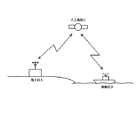
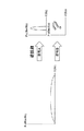
本発明に関連する衛星通信システムとしては、図8に示すように、陸上にある地上局Aと、海上にある移動局Bとが人工衛星Cを介して通信を行う場合、その通信をスペクトラム拡散通信方式にて行うシステムがある。下記の特許文献1には、衛星通信チャネルの寿命テスト初期におけるシステム間の調整を行う際に、クリーン搬送信号をスペクトラム拡散方式で変調することが記載されている。
As shown in FIG. 8, when a ground station A on land and a mobile station B on the sea communicate with each other via an artificial satellite C, the satellite communication system related to the present invention is spread spectrum. There are systems that use communication methods.
ここで、スペクトラム拡散通信方式とは、図9に示すように、送信側において、送信データをある符号で拡散して符号化データを作成し、その符号化データを受信側に送信するとともに、図10に示すように、受信側において、受信した符号化データを上記の符号で逆拡散することで受信データを生成する方式である。 Here, the spread spectrum communication system means that, as shown in FIG. 9, on the transmitting side, transmission data is spread with a certain code to generate encoded data, and the encoded data is transmitted to the receiving side. As shown in FIG. 10, on the receiving side, received data is generated by despreading the received encoded data with the above code.
このように、スペクトラム拡散通信方式では、送信データに固有の符号を用いて拡散することによって、秘匿性の高いデータを送信側と受信側との間で送受信することができる。 As described above, in the spread spectrum communication system, highly confidential data can be transmitted and received between the transmission side and the reception side by spreading using transmission data with a unique code.
また、上記のスペクトラム拡散通信方式では、送信側において、同じ周波数帯で複数の信号を多重して送信しても、図11に示すように、受信側で固有の符号(符号A〜D)を用いて逆拡散を行うことで、各々の信号[CH(チャネル)1〜CH4]を復元することができる。 Further, in the above spread spectrum communication system, even if a plurality of signals are multiplexed and transmitted in the same frequency band on the transmission side, as shown in FIG. 11, unique codes (codes A to D) are set on the reception side. Each signal [CH (channel) 1 to CH4] can be restored by using the despreading.
この場合、送信側において、固有の符号を用いて拡散されたデータは、図12に示すように、信号がノイズに埋もれているため、そのデータを受信した側で逆拡散を行わない限り、信号が検知されにくいという特徴を持つ。この特徴は、回線秘匿と呼ばれている。但し、データを受信した側で逆拡散を行う場合には、ノイズに埋もれていた信号を検知することができる。 In this case, as shown in FIG. 12, the data spread by using a unique code on the transmission side is signal-buried in noise, so unless the signal is despread on the side receiving the data, Is difficult to detect. This feature is called line concealment. However, when despreading is performed on the data receiving side, a signal buried in noise can be detected.
また、送信側において、固有の符号を用いて拡散されたデータは、図13に示すように、逆拡散を行う際に拡散符号を知らなければ、信号を受信することが困難である。この特徴は、データの秘匿と呼ばれている。例えば、符号Aで拡散したデータは、符号Aで逆拡散を行うことで受信することができるが、符号Bで逆拡散を行うと受信することができない。 On the transmission side, as shown in FIG. 13, it is difficult to receive data from data spread using a unique code unless the spreading code is known when despreading is performed. This feature is called data concealment. For example, data spread with code A can be received by performing despreading with code A, but cannot be received with despreading with code B.
送信データを拡散する場合には、図14(a)に示すように、例えば送信データ「010」と拡散符号「101110010111001011100」との排他的否定論理和(ENOR)をとることで、符号化データ「010001110111000100011」を得る。 In the case of spreading the transmission data, as shown in FIG. 14A, for example, an exclusive negative logical sum (ENOR) of the transmission data “010” and the spread code “101110010111001011100” is taken, 010001110111000100011 "is obtained.
受信データを逆拡散する場合には、図14(b)に示すように、例えば受信データ(符号化データ)「010001110111000100011」と拡散符号「101110010111001011100」との排他的否定論理和(ENOR)をとることで、受信データ「010」を得る。 When the received data is despread, as shown in FIG. 14B, for example, exclusive negative logical sum (ENOR) of the received data (encoded data) “010001110111000100011” and the spread code “101110010111001011100” is taken. Thus, the received data “010” is obtained.
ここで、受信データを逆拡散する場合には、図15(a)に示すように、受信信号と拡散符号とを比較することで、拡散符号(例えば、符号A)との相関を調べ、図15(b)に示すように、相関度が一定の閾値を超える時にその極大点を同期点としている。 Here, when the received data is despread, as shown in FIG. 15A, the correlation between the received signal and the spread code is compared to check the correlation with the spread code (for example, code A). As shown in FIG. 15 (b), when the degree of correlation exceeds a certain threshold, the maximum point is set as a synchronization point.
しかしながら、上述したスペクトラム拡散通信方式では、図16に示すように、異なるチャネル間において受信信号の強度に著しく差があると、図17に示すように、同期点を誤検出してしまうことがあり、相互干渉によって受信に支障をきたす場合がある。 However, in the above-described spread spectrum communication method, as shown in FIG. 16, if there is a significant difference in received signal strength between different channels, a synchronization point may be erroneously detected as shown in FIG. In some cases, reception may be hindered by mutual interference.
図17(a)では、図16(a)に示すように、受信側と送信側(CH1)との距離と、受信側と送信側(CH2)との距離とがほぼ同じであり、異なるチャネル(CH1,CH2)間において受信信号の強度に著しく差を生じないため、同期点の誤検出は生じない。 In FIG. 17 (a), as shown in FIG. 16 (a), the distance between the receiving side and the transmitting side (CH1) and the distance between the receiving side and the transmitting side (CH2) are almost the same, and different channels are used. Since there is no significant difference in received signal strength between (CH1, CH2), no erroneous detection of the synchronization point occurs.
図17(b)では、図16(b)に示すように、受信側と送信側(CH1)との距離よりも、受信側と送信側(CH2)との距離が短いため、異なるチャネル(CH1,CH2)間において受信信号の強度に著しく差が生じてしまい、同期点の誤検出が生じ、相互干渉によって受信に支障をきたしてしまう。 In FIG. 17B, as shown in FIG. 16B, since the distance between the receiving side and the transmitting side (CH2) is shorter than the distance between the receiving side and the transmitting side (CH1), different channels (CH1 , CH2), a significant difference occurs in the intensity of the received signal, a false detection of the synchronization point occurs, and reception is hindered by mutual interference.
上記の特許文献1には、クリーン搬送信号をスペクトラム拡散方式で変調することが記載されているが、上記のように、異なるチャネル間において受信信号の強度に著しく差があると、相互干渉によって受信に支障をきたしてしまうこととなる。
The
そこで、本発明の目的は上記の問題点を解消し、異なるチャネル間において受信信号の強度に著しく差があっても、それらの相互干渉を軽減することができる衛星通信システム、送信装置、受信装置及びそれらに用いる衛星通信方法を提供することにある。 Therefore, an object of the present invention is to solve the above-described problems, and even if there is a significant difference in received signal strength between different channels, a satellite communication system, a transmitting apparatus, and a receiving apparatus that can reduce their mutual interference And providing a satellite communication method used for them.
本発明による衛星通信システムは、スペクトラム拡散通信方式において拡散符号毎に異なる中心周波数を割り当てる手段を送信回路及び受信回路のうちの少なくとも一方に備えている。 The satellite communication system according to the present invention includes means for allocating a different center frequency for each spread code in at least one of the transmission circuit and the reception circuit in the spread spectrum communication system.
本発明による送信装置は、スペクトラム拡散通信方式において拡散符号毎に異なる中心周波数を割り当てる手段を備えている。 The transmission apparatus according to the present invention includes means for assigning a different center frequency for each spread code in the spread spectrum communication system.
本発明による受信装置は、スペクトラム拡散通信方式において拡散符号毎に異なる中心周波数を割り当てる手段を備えている。 The receiving apparatus according to the present invention comprises means for assigning a different center frequency for each spreading code in the spread spectrum communication system.
本発明による衛星通信方法は、送信回路及び受信回路のうちの少なくとも一方において、スペクトラム拡散通信方式において拡散符号毎に異なる中心周波数を割り当てる処理を実行している。 In the satellite communication method according to the present invention, at least one of the transmission circuit and the reception circuit executes a process of assigning a different center frequency for each spread code in the spread spectrum communication system.
本発明は、上記のような構成及び動作とすることで、異なるチャネル間において受信信号の強度に著しく差があっても、それらの相互干渉を軽減することができるという効果が得られる。 By adopting the configuration and operation as described above, the present invention can reduce the mutual interference even if there is a significant difference in received signal strength between different channels.
次に、本発明の実施の形態について図面を参照して説明する。まず、図1及び図2を参照して本発明の概念について説明する。図1は本発明による送信部回路の構成を示すブロック図であり、図2は本発明による受信部回路の構成を示すブロック図である。 Next, embodiments of the present invention will be described with reference to the drawings. First, the concept of the present invention will be described with reference to FIGS. FIG. 1 is a block diagram showing a configuration of a transmitter circuit according to the present invention, and FIG. 2 is a block diagram showing a configuration of a receiver circuit according to the present invention.
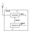
図1において、送信部回路1は、変調周波数指定が入力されると、指定された変調周波数を発生する周波数発生部11と、入力された符号化データを周波数発生部11からの変調周波数で変換して変調信号を出力する周波数変換部12と、変調信号を送信する空中線13とから構成されている。
In FIG. 1, when a modulation frequency designation is input, the
周波数発生部11は変調周波数指定に応じて拡散符号毎に異なる固有の周波数を発生させる。周波数変換部12は、周波数発生部11からの変調周波数にて拡散符号毎に異なる固有の周波数に変換し、その変換した変調信号を空中線13へと出力する。
The
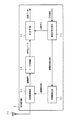
図2において、受信部回路2は、送信部回路1の空中線13から送信された変調信号を受信する空中線21と、変調周波数指定が入力されると、指定された復調周波数を発生する周波数発生部22と、空中線で受信した変調信号を周波数発生部22からの復調周波数で変換して復調信号を出力する周波数変換部23とから構成されている。
In FIG. 2, the
周波数発生部22は復調周波数指定に応じて拡散符号毎に異なる固有の周波数を発生させる。周波数変換部23は、空中線21で受信した変調信号を、拡散符号毎に異なる固有の周波数にて変換し、その変換した復調信号を次段の回路へと出力する
The
このように、本発明は、拡散符号毎に異なる中心周波数を割り当てることによって、他のチャネルとの相関を抑えることができ、拡散符号毎に他のチャネルとの相関度を下げることができる。よって、本発明では、異なるチャネル間において受信信号の強度に著しく差があっても、それらの相互干渉を軽減することができる。 Thus, the present invention can suppress the correlation with other channels by assigning a different center frequency for each spreading code, and can reduce the degree of correlation with other channels for each spreading code. Therefore, in the present invention, even if there is a significant difference in received signal strength between different channels, mutual interference can be reduced.
特に、本発明は、図1に示す送信部回路1を図8に示す移動局Bに搭載し、図2に示す受信部回路2を図8に示す地上局Aに搭載することで、地上局Aが送信した信号が人工衛星Cで折り返されて、移動局Bから送信される信号と重なり、地上局Aにおいて異なるチャネル間において受信信号の強度に著しく差が生ずる場合に有効である。
In particular, according to the present invention, the
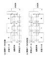
図3は本発明の実施の形態による送信部回路の構成例を示すブロック図である。図3において、送信部回路1は、周波数発生部11と、周波数変換部12と、空中線13と、拡散符号生成部14と、符号拡散部15と、D/A(ディジタル/アナログ)変換部16とから構成されている。尚、周波数発生部11、周波数変換部12、空中線13はそれぞれ、上記の図1に示す周波数発生部11、周波数変換部12、空中線13と同様の動作を行う。
FIG. 3 is a block diagram showing a configuration example of the transmitter circuit according to the embodiment of the present invention. In FIG. 3, the
送信部回路1において、拡散符号生成部14は、使用する拡散符号が選択されると、その選択された拡散符号を生成して符号拡散部15に出力する。また、拡散符号生成部14は、生成した拡散符号の変調周波数を指定するために、変調周波数指定を周波数発生部11に出力する。
In the
符号拡散部15は、送信データが入力されると、その送信データを固有の符号(拡散符号生成部14からの拡散符号)で拡散し、符号化データを出力する。D/A変換部16は、入力された符号化データをアナログ信号に変換して周波数変換部12へ出力する。
When the transmission data is input, the
周波数発生部11は、拡散符号生成部14からの変調周波数指定に応じて、拡散符号毎に異なる固有の周波数を発生させ、変調周波数として周波数変換部12に出力する。周波数変換部12は、周波数発生部11からの変調周波数に基づいて、D/A変換部16からのアナログ信号(符号化データ)を、拡散符号毎に異なる固有の周波数に変換し、変調信号を空中線13に出力する。空中線13は、周波数変換部12からの変調信号を受信部回路2に対して送信する。
The
図4は本発明の実施の形態による受信部回路の構成例を示すブロック図である。図4において、受信部回路2は、空中線21と、周波数発生部22と、周波数変換部23と、拡散符号生成部24と、A/D(アナログ/ディジタル)変換部25と、逆拡散部26とから構成されている。
FIG. 4 is a block diagram showing a configuration example of the receiver circuit according to the embodiment of the present invention. In FIG. 4, the
受信部回路2において、拡散符号生成部24は、使用する拡散符号が選択されると、その選択された拡散符号を生成して逆拡散部26に出力する。また、拡散符号生成部24は、生成した拡散符号の復調周波数を指定するために、復調周波数指定を周波数発生部22に出力する。
In the receiving
周波数発生部22は、拡散符号生成部24からの復調周波数指定に応じて、拡散符号毎に異なる固有の周波数を発生させ、復調周波数として周波数変換部23に出力する。周波数変換部23は、周波数発生部22からの復調周波数に基づいて、空中線21にて受信した信号を、拡散符号毎に異なる固有の周波数にて変換し、復調信号をA/D変換部25に出力する。
The
A/D変換部15は、周波数変換部23で変換された復調信号をディジタル信号(符号化データ)に変換し、その符号化データを逆拡散部26に出力する。逆拡散部26は、A/D変換部15から符号化データが入力されると、その送符号化データを固有の符号(拡散符号生成部24からの拡散符号)で逆拡散し、受信データを出力する。
The A /
図5(a)は本発明の実施の形態による拡散符号に対する中心周波数の割り当てを示す図であり、図5(b)は図5(a)における符号とチャネルとの相関度を示す図である。 FIG. 5A is a diagram showing assignment of the center frequency to the spreading code according to the embodiment of the present invention, and FIG. 5B is a diagram showing the degree of correlation between the code and the channel in FIG. 5A. .
本実施の形態では、図5(a)に示すように、各チャネル(CH1,CH2,CH3,・・・)の拡散符号(符号A,符号B,符号C,・・・)毎に、異なる中心周波数[fA (Hz),fB (Hz),fC (Hz),・・・]を割り当てている。 In the present embodiment, as shown in FIG. 5 (a), each channel (CH1, CH2, CH3,...) Has a different spread code (code A, code B, code C,...). Center frequencies [f A (Hz), f B (Hz), f C (Hz),...] Are assigned.
これによって、本実施の形態において、例えばチャネルCH1の符号Aは、他のチャネルCH2,CH3,・・・の符号B,符号C,・・・との相関が抑えられるので、図5(b)に示すように、符号Aと他のチャネルCH2との相関度が下がることとなる。 Accordingly, in the present embodiment, for example, the code A of the channel CH1 is suppressed from being correlated with the codes B, C,... Of the other channels CH2, CH3,. As shown in FIG. 5, the correlation between the code A and the other channel CH2 is lowered.
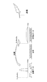
図6は本発明の実施の形態における変調信号と復調信号との関係を示す図である。この図6を参照して本実施の形態における変調信号と復調信号との関係について説明する。 FIG. 6 is a diagram showing the relationship between the modulated signal and the demodulated signal in the embodiment of the present invention. The relationship between the modulated signal and the demodulated signal in the present embodiment will be described with reference to FIG.
本実施の形態においては、ベースバンド信号をai (t) 、変調周波数をω1 とすると、変調信号は、
変調信号=ai cosω1 t
で表される。
In the present embodiment, when the baseband signal is a i (t) and the modulation frequency is ω 1 , the modulation signal is
Modulation signal = a i cos ω 1 t
It is represented by
また、復調周波数をω2 とすると、復調信号は、
復調信号=ai (t) cosω1 t×cosω2 t
=1/2[ai (t) cos(ω1 −ω2 )t]
+1/2[ai (t) cos(ω1 +ω2 )t]
で表される。
If the demodulation frequency is ω 2 , the demodulated signal is
Demodulated signal = a i (t) cos ω 1 t × cos ω 2 t
= 1/2 [a i (t) cos (ω 1 −ω 2 ) t]
+1/2 [a i (t) cos (ω 1 + ω 2 ) t]
It is represented by
図6において、モデム1において変調周波数ω1 で変調された変調信号[=ai cosω1 t]は、モデム2において復調周波数ω2 で復調されて復調信号[=1/2[ai cos(ω1 −ω2 )t]となる。
In FIG. 6, the modulation signal [= a i cos ω 1 t] modulated at the modulation frequency ω 1 in the
この場合、モデム2では、復調信号の1/2[ai (t) cos(ω1 +ω2 )t]をフィルタで除去している。したがって、復調信号の1/2[ai (t) cos(ω1 −ω2 )t]において(ω1 −ω2 )が小さければ安定することになる。
In this case, the
したがって、本実施の形態では、拡散符号毎に変調周波数、復調周波数を固有の値とし、同じ拡散符号の変調周波数と復調周波数との差を小さくすることによって、異なる拡散符号の信号との相関が小さくなるようにすることができる。 Therefore, in this embodiment, the modulation frequency and the demodulation frequency are set to unique values for each spreading code, and the difference between the modulation frequency and the demodulation frequency of the same spreading code is reduced, so that the correlation between the signals of different spreading codes can be increased. It can be made smaller.
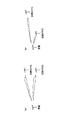
図7は本発明の実施の形態における拡散符号の変調周波数と復調周波数との差による違いを示す図である。図7に示すように、拡散符号の変調周波数と復調周波数との差(ω1 −ω2 )が比較的に小さければ、相関度に対する影響は小さくなり、その波形がベースバンド信号ai (t) の波形に近くなり、初期同期補足(図15に示す同期点の検出)が容易となる。 FIG. 7 is a diagram showing the difference due to the difference between the modulation frequency and the demodulation frequency of the spreading code in the embodiment of the present invention. As shown in FIG. 7, if the difference (ω 1 −ω 2 ) between the modulation frequency and the demodulation frequency of the spread code is relatively small, the influence on the degree of correlation is small, and the waveform is the baseband signal a i (t ) And the initial synchronization supplement (synchronization point detection shown in FIG. 15) becomes easy.
しかしながら、拡散符号の変調周波数と復調周波数との差(ω1 −ω2 )が比較的に大きくなると、相関度に対する影響は大きくなり、ベースバンド信号ai (t) の波形とは異なる波形となり、初期同期補足(図15に示す同期点の検出)が取りにくくなる。 However, when the difference (ω 1 −ω 2 ) between the modulation frequency and the demodulation frequency of the spreading code becomes relatively large, the influence on the correlation degree becomes large, and the waveform is different from the waveform of the baseband signal a i (t). Therefore, initial synchronization supplement (detection of the synchronization point shown in FIG. 15) is difficult to take.
このように、本実施の形態では、拡散符号毎に異なる中心周波数を割り当てることによって、他のチャネル(に用いる拡散符号)との相関を抑えることができ、拡散符号毎に他のチャネルとの相関度を下げることができる。よって、本実施の形態では、異なるチャネル間において受信信号の強度に著しく差があっても、それらの相互干渉を軽減することができる。 Thus, in this embodiment, by assigning a different center frequency for each spreading code, correlation with other channels (spread codes used for) can be suppressed, and correlation with other channels for each spreading code. The degree can be lowered. Therefore, in this embodiment, even if there is a significant difference in received signal strength between different channels, mutual interference can be reduced.
1 送信部回路
2 受信部回路
11,22 周波数発生部
12,23 周波数変換部
13,21 空中線
14,24 拡散符号生成部
15 符号拡散部
16 D/A変換部
25 A/D変換部
26 逆拡散部
1 Transmitter circuit
2 Receiving
Claims (16)
Priority Applications (1)
| Application Number | Priority Date | Filing Date | Title |
|---|---|---|---|
| JP2008038125A JP2009200657A (en) | 2008-02-20 | 2008-02-20 | Satellite communications system, transmitter, receiver, and satellite communication method used for them |
Applications Claiming Priority (1)
| Application Number | Priority Date | Filing Date | Title |
|---|---|---|---|
| JP2008038125A JP2009200657A (en) | 2008-02-20 | 2008-02-20 | Satellite communications system, transmitter, receiver, and satellite communication method used for them |
Publications (1)
| Publication Number | Publication Date |
|---|---|
| JP2009200657A true JP2009200657A (en) | 2009-09-03 |
Family
ID=41143721
Family Applications (1)
| Application Number | Title | Priority Date | Filing Date |
|---|---|---|---|
| JP2008038125A Pending JP2009200657A (en) | 2008-02-20 | 2008-02-20 | Satellite communications system, transmitter, receiver, and satellite communication method used for them |
Country Status (1)
| Country | Link |
|---|---|
| JP (1) | JP2009200657A (en) |
Cited By (2)
| Publication number | Priority date | Publication date | Assignee | Title |
|---|---|---|---|---|
| US8699465B2 (en) | 2009-11-30 | 2014-04-15 | Qualcomm Incorporated | Forward link data rate control and rate indication for satellite-enabled communications systems |
| JP2015185916A (en) * | 2014-03-20 | 2015-10-22 | 日本電気株式会社 | Communication device and communication system |
Citations (4)
| Publication number | Priority date | Publication date | Assignee | Title |
|---|---|---|---|---|
| JPS6374235A (en) * | 1986-09-17 | 1988-04-04 | Nec Corp | Spread spectrum communication system |
| JPH07115681A (en) * | 1993-10-19 | 1995-05-02 | Tec Corp | Spread spectrum radio communication method |
| JPH07212828A (en) * | 1994-01-14 | 1995-08-11 | Tec Corp | Spread spectrum communication method |
| JP2001016220A (en) * | 1999-06-30 | 2001-01-19 | Adtec:Kk | Radio transmission system |
-
2008
- 2008-02-20 JP JP2008038125A patent/JP2009200657A/en active Pending
Patent Citations (4)
| Publication number | Priority date | Publication date | Assignee | Title |
|---|---|---|---|---|
| JPS6374235A (en) * | 1986-09-17 | 1988-04-04 | Nec Corp | Spread spectrum communication system |
| JPH07115681A (en) * | 1993-10-19 | 1995-05-02 | Tec Corp | Spread spectrum radio communication method |
| JPH07212828A (en) * | 1994-01-14 | 1995-08-11 | Tec Corp | Spread spectrum communication method |
| JP2001016220A (en) * | 1999-06-30 | 2001-01-19 | Adtec:Kk | Radio transmission system |
Cited By (2)
| Publication number | Priority date | Publication date | Assignee | Title |
|---|---|---|---|---|
| US8699465B2 (en) | 2009-11-30 | 2014-04-15 | Qualcomm Incorporated | Forward link data rate control and rate indication for satellite-enabled communications systems |
| JP2015185916A (en) * | 2014-03-20 | 2015-10-22 | 日本電気株式会社 | Communication device and communication system |
Similar Documents
| Publication | Publication Date | Title |
|---|---|---|
| CA2091785C (en) | Synchronous spread spectrum communications system and method | |
| CA2902073C (en) | Improvement of spread spectrum gmsk signals | |
| US8300721B2 (en) | Pseudorandom noise code acquisition in direct sequence spread spectrum systems | |
| WO2016169414A1 (en) | Multiuser information processing method and apparatus | |
| JPH08509590A (en) | Method and apparatus for time division multiplexing the use of spreading codes in a communication system | |
| US7957454B2 (en) | Transmitter, receiver, and data communications system and method | |
| US7844292B2 (en) | System and method for in-band control signaling using bandwidth distributed encoding | |
| KR101458390B1 (en) | Apparatus and method for transmitting/receiving data in a communication system | |
| JP2009200657A (en) | Satellite communications system, transmitter, receiver, and satellite communication method used for them | |
| JP4391514B2 (en) | Mixed multiplex transmission / reception apparatus and method in wireless communication system | |
| JP4901497B2 (en) | Communication system, transmitter, receiver, communication method, transmitter detection method, communication procedure setting method | |
| RU2221344C2 (en) | Device for code-division transmission and reception of digital information using broadband noise-like signals | |
| JP2011188316A (en) | Frequency hopping radio communication device and frequency hopping method of the same, and transmitter and receiver | |
| JP2001223674A (en) | Spread spectrum demodulator | |
| JP4077398B2 (en) | Wireless communication system, wireless communication method, and transmitter | |
| JP2556141B2 (en) | Spread spectrum communication system | |
| KR102650673B1 (en) | Underwater communication apparatus and method using css signal | |
| JP2008283514A (en) | Noise component estimating device, and receiver | |
| US20090052501A1 (en) | Voice communication apparatus | |
| JP3715399B2 (en) | Communication apparatus using code division multiple access system | |
| JP3432419B2 (en) | Spread spectrum communication system | |
| JP6370254B2 (en) | Transmission device, reception device, and transmission / reception device | |
| JP2018133689A (en) | Visible light communication system and visible light communication method | |
| WO2020210762A1 (en) | Analog pulse sequence encoding and cycle recovery for spectrum efficient high density data | |
| JP2020178184A (en) | Wireless communication device, wireless communication system, and wireless communication method |
Legal Events
| Date | Code | Title | Description |
|---|---|---|---|
| A621 | Written request for application examination |
Free format text: JAPANESE INTERMEDIATE CODE: A621 Effective date: 20110113 |
|
| A977 | Report on retrieval |
Free format text: JAPANESE INTERMEDIATE CODE: A971007 Effective date: 20120724 |
|
| A131 | Notification of reasons for refusal |
Free format text: JAPANESE INTERMEDIATE CODE: A131 Effective date: 20120731 |
|
| A521 | Written amendment |
Free format text: JAPANESE INTERMEDIATE CODE: A523 Effective date: 20121001 |
|
| A02 | Decision of refusal |
Free format text: JAPANESE INTERMEDIATE CODE: A02 Effective date: 20121225 |