JP2009200375A - Movable transformer - Google Patents
Movable transformer Download PDFInfo
- Publication number
- JP2009200375A JP2009200375A JP2008042421A JP2008042421A JP2009200375A JP 2009200375 A JP2009200375 A JP 2009200375A JP 2008042421 A JP2008042421 A JP 2008042421A JP 2008042421 A JP2008042421 A JP 2008042421A JP 2009200375 A JP2009200375 A JP 2009200375A
- Authority
- JP
- Japan
- Prior art keywords
- transformer
- transport vehicle
- container
- main body
- winding
- Prior art date
- Legal status (The legal status is an assumption and is not a legal conclusion. Google has not performed a legal analysis and makes no representation as to the accuracy of the status listed.)
- Granted
Links
- 238000004804 winding Methods 0.000 claims abstract description 18
- XEEYBQQBJWHFJM-UHFFFAOYSA-N Iron Chemical group [Fe] XEEYBQQBJWHFJM-UHFFFAOYSA-N 0.000 claims abstract description 6
- 238000001816 cooling Methods 0.000 claims abstract description 5
- NJPPVKZQTLUDBO-UHFFFAOYSA-N novaluron Chemical compound C1=C(Cl)C(OC(F)(F)C(OC(F)(F)F)F)=CC=C1NC(=O)NC(=O)C1=C(F)C=CC=C1F NJPPVKZQTLUDBO-UHFFFAOYSA-N 0.000 claims description 10
- 239000000463 material Substances 0.000 claims description 8
- 230000003028 elevating effect Effects 0.000 claims 1
- 238000010276 construction Methods 0.000 description 3
- 230000005611 electricity Effects 0.000 description 2
- 238000007689 inspection Methods 0.000 description 2
- 230000001681 protective effect Effects 0.000 description 2
- 239000000725 suspension Substances 0.000 description 2
- 230000008859 change Effects 0.000 description 1
- 239000004020 conductor Substances 0.000 description 1
- 230000000694 effects Effects 0.000 description 1
- 238000009413 insulation Methods 0.000 description 1
- 230000007246 mechanism Effects 0.000 description 1
- 238000000034 method Methods 0.000 description 1
- 230000000116 mitigating effect Effects 0.000 description 1
- 238000012986 modification Methods 0.000 description 1
- 230000004048 modification Effects 0.000 description 1
- 230000008439 repair process Effects 0.000 description 1
- 230000004044 response Effects 0.000 description 1
Images


Landscapes
- Housings And Mounting Of Transformers (AREA)
Abstract
【課題】移動用変圧器を運搬車両に着脱自在に構成することで、移動用変圧器を簡単にトラック等の運搬車両に搭載することができ、かつその移動用変圧器を必要な場所に容易に設置する。
【解決手段】運搬車両Tに積載して移動することができる移動用変圧器であって、鉄心に巻線を巻装し、巻線を収容する本体タンクと、本体タンク外部へ巻線の端子を引き出すブッシング3,4と、本体タンク内を冷却する放熱器5とから成る変圧器本体1と、変圧器本体1を載せる略長方形状の板材のコンテナ台座7と、コンテナ台座7の一側に運搬車両Tの荷台に牽引して積載する際に掛け止める係止構造8と、コンテナ台座7の後方側に案内車輪9をそれぞれ具備したコンテナ2とを備えた。
【選択図】図3An object of the present invention is to provide a mobile transformer that can be attached to and detached from a transport vehicle so that the transport transformer can be easily mounted on a transport vehicle such as a truck, and the mobile transformer can be easily installed at a necessary place. Install in.
A transfer transformer that can be loaded and moved on a transport vehicle T, has a winding wound around an iron core, accommodates the winding, and a terminal of the winding outside the tank. A transformer body 1 comprising bushings 3 and 4 for drawing out the heat and a radiator 5 for cooling the inside of the main body tank, a container base 7 made of a substantially rectangular plate on which the transformer body 1 is placed, and one side of the container base 7 There are provided a locking structure 8 that is latched when being pulled and loaded on the loading platform of the transport vehicle T, and a container 2 that is provided with guide wheels 9 on the rear side of the container base 7.
[Selection] Figure 3
Description
本発明は、電力系統又は変電所において事故が生じた際に、変圧器をトラック等に積載して移動使用可能に構成した移動用変圧器に関する。 The present invention relates to a moving transformer configured such that a transformer is mounted on a truck or the like and can be used when an accident occurs in an electric power system or a substation.
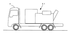
電力系統又は変電所において事故が生じた際、更に工事用電源或いは災害時の緊急電源確保のために使用される移動用変圧器が提案されている。この移動用変圧器は、トラック又はトレーラーに積載したまま移動可能な変圧器で、配電用変圧器の特別高圧(110kV〜22kV)で受電した電気を配電電圧(22kV〜6kV)に降圧する変圧器の事故時や変電所機器の点検・修理などの場合に電気を供給するために、幾つかの変電所の共通予備として使用することができる。図7の側面図に示すように、従来は車両Tに移動変圧器51を一体化した構造のものが提案されている。
When an accident occurs in an electric power system or a substation, a moving transformer used for securing a construction power source or an emergency power source in case of a disaster has been proposed. This transformer for movement is a transformer that can be moved while being loaded on a truck or trailer. The transformer that steps down the electricity received at the extra high voltage (110 kV to 22 kV) of the distribution transformer to the distribution voltage (22 kV to 6 kV). It can be used as a common spare for several substations in order to supply electricity in case of accidents or inspection / repair of substation equipment. As shown in the side view of FIG. 7, a structure in which a
例えば、変圧器、開閉器、ケーブル及び保護装置を収納し、柱上変圧器の吊り替えを無停電で行う移動用変圧器については、特許文献1の特開平10−224918号の「移動用変圧器装置」のように、車両の荷台に搭載され、変圧器、開閉器、ケーブル及び保護装置を収納した箱体と、この箱体の下面の四隅を含む数個所に固着された足ゴムと、箱体の上面に設けられた複数個の吊り金具と、それぞれの両端が各吊り金具と荷台に接続され、箱体を前記荷台に固定した複数本のワイヤとを備えたものが提案されている。
また、特許文献2の特開平10−201019号の「トレーラ式工事用変圧器」のように、柱上変圧器に対し並列となるよう配電線に接続される工事用変圧器であって、トレーラが設けられ、トレーラ上にはコンテナが搭載され、コンテナ内に柱上変圧器本体が収納され、柱上変圧器本体には高圧側入力部と低圧側出力部とが設けられたものも提案されている。
しかし、特許文献1の「移動用変圧器装置」のような自走式の移動変圧器は、事故時の即応性確保のため、トラックのような専用車両に常時積載した状態で保管していた。このような自走式移動変圧器の稼動は非常に少なく、トラックの車両部分が本来の輸送業務に供していないため無駄であった。トラックの車両部分は稼動の有無に関わらず定期点検費用が発生するという問題があった。
However, a self-propelled mobile transformer such as the “Transformer Transformer Device” in
また、特許文献1の「移動用変圧器装置」は変圧器、開閉器、ケーブル、保護装置を収容した箱を車両の荷台に搭載したものであり、その固定は上部に複数放置した吊り金具と荷台とをワイヤーで接続するものであった。箱の積み下ろしは車両単体ではできないため、クレーンやユニックが必要となり、その搭載作業が大がりなりやすいという問題があった。
In addition, the "Transformer Transformer Device" of
本発明は、かかる問題点を解決するために創案されたものである。すなわち、本発明の目的は、移動用変圧器を運搬車両に着脱自在に構成することで、移動用変圧器を簡単にトラック等の運搬車両に搭載することができ、かつその移動用変圧器を必要な場所に容易に設置することができる移動用変圧器を提供することにある。 The present invention has been developed to solve such problems. That is, an object of the present invention is to make it possible to easily mount a moving transformer on a transporting vehicle such as a truck by configuring the moving transformer so as to be detachable from the transporting vehicle. An object of the present invention is to provide a mobile transformer that can be easily installed at a required place.
本発明によれば、運搬車両(T)に積載して移動することができる移動用変圧器であって、鉄心に巻線を巻装し、該巻線を収容する本体タンクと、該本体タンク外部へ該巻線の端子を引き出すブッシング(3,4)と、該本体タンク内を冷却する放熱器(5)とから成る変圧器本体(1)と、前記変圧器本体(1)を載せる略長方形状の板材のコンテナ台座(7)と、該コンテナ台座(7)の一側に前記運搬車両(T)の荷台に牽引して積載する際に掛け止める係止構造(8)と、該コンテナ台座(7)の後方側に案内車輪(9)をそれぞれ具備したコンテナ(2)と、を備えた、ことを特徴とする移動用変圧器が提供される。
前記コンテナ台座(7)の前方側に伸縮自在になる支持脚(11)を設けることが好ましい。
According to the present invention, a transformer for movement that can be loaded and moved on a transport vehicle (T), wherein a winding is wound around an iron core, and a main body tank that houses the winding, and the main body tank A transformer body (1) composed of a bushing (3, 4) for pulling out the terminal of the winding to the outside, a radiator (5) for cooling the inside of the body tank, and an abbreviation for mounting the transformer body (1) A container base (7) made of a rectangular plate material, a locking structure (8) to be latched when being pulled and loaded on one side of the container base (7) by the carrier of the transport vehicle (T), and the container There is provided a moving transformer comprising a container (2) provided with guide wheels (9) on the rear side of a pedestal (7).
It is preferable to provide a support leg (11) which can be expanded and contracted on the front side of the container base (7).
また、運搬車両(T)に積載して移動することができる移動用変圧器であって、鉄心に巻線を巻装し、該巻線を収容する本体タンクと、該本体タンク外部へ該巻線の端子を引き出すブッシング(3,4)と、該本体タンク内を冷却する放熱器(5)とから成る変圧器本体(1)と、前記変圧器本体(1)を載せる略長方形状の板材のコンテナ台座(7)と、前記コンテナ台座(7)の前方側と後方側にそれぞれ設けた、昇降自在になる昇降装置(13)と、各昇降装置(13)の下端に取り付けた車輪(14)と、を備えたものにすることができる。 Further, the transformer is a transfer transformer that can be loaded and moved on a transport vehicle (T), and a winding is wound around an iron core, and a main body tank that accommodates the winding, and the winding outside the main body tank. Transformer body (1) comprising bushings (3, 4) for drawing out wire terminals, and radiator (5) for cooling the inside of the body tank, and a substantially rectangular plate material on which the transformer body (1) is placed Container pedestal (7), lifting and lowering device (13) provided on the front side and the rear side of the container pedestal (7), respectively, and wheels (14) attached to the lower end of each lifting device (13) ) And can be provided.
上記構成の発明では、移動変圧器をトラック等の運搬車両(T)に着脱自在に構成することで、必要に応じて移動用変圧器を運搬車両(T)に簡単に搭載することができる。この運搬車両(T)に搭載するときも、運搬車両(T)自体で本発明の移動変圧器をコンテナ(2)ごと運搬車両(T)に搭載することができ、クレーンやユニックを使用しないでも、容易かつ迅速にその搭載作業を完了させることができる。 In the invention of the above configuration, the moving transformer can be easily mounted on the transporting vehicle (T) as required by configuring the mobile transformer so as to be detachable from the transporting vehicle (T) such as a truck. Even when mounted on the transport vehicle (T), the transport transformer of the present invention can be mounted on the transport vehicle (T) together with the container (2) by the transport vehicle (T) itself, without using a crane or unic. The mounting operation can be completed easily and quickly.
また、変圧器本体(1)を載せる略長方形状の板材のコンテナ台座(7)と、コンテナ台座(7)の前方側と後方側にそれぞれ設けた、昇降自在になる昇降装置(13)と、各昇降装置(13)の下端に取り付けた車輪(14)と、を備えた構造のものでは、変圧器本体(1)を常時水平に維持しながら上下動させることができるので、変圧器本体(1)を傾斜させることがないので絶縁油が漏洩することがない。 Also, a container base (7) of a substantially rectangular plate material on which the transformer body (1) is placed, a lifting device (13) that can be moved up and down provided on the front side and the rear side of the container base (7), In the structure having a wheel (14) attached to the lower end of each lifting and lowering device (13), the transformer body (1) can be moved up and down while being always kept horizontal. Since 1) is not inclined, the insulating oil does not leak.
本発明の移動用変圧器は、変圧器本体を載せる略長方形状の板材のコンテナ台座と、コンテナ台座の一側に運搬車両の荷台に牽引して積載する際に掛け止める係止構造と、コンテナ台座の後方側に車輪をそれぞれ具備したコンテナとを備えたものであり、運搬車両に容易に積載して移動することができる構造のものである。 The transfer transformer of the present invention includes a container base of a substantially rectangular plate material on which the transformer main body is placed, a locking structure that is latched when being pulled and loaded on the carrier bed of one side of the container base, and the container The container is provided with a container provided with wheels on the rear side of the pedestal, and can be easily loaded and moved on a transport vehicle.
以下、本発明の好ましい実施の形態を図面を参照して説明する。
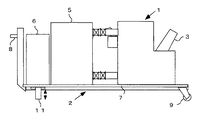
図1は実施例1の移動用変圧器を示す側面図である。図2は実施例1の移動用変圧器を示す平面図である。図3は実施例1の移動用変圧器をトラックに搭載した状態を示す側面図である。
本発明の移動用変圧器は、鉄心に巻線を巻装し、この巻線を収容するために変圧器油を充填した外箱となる本体タンクとから成る変圧器本体1と、この変圧器本体1を載せるコンテナ2とを備えたものである。変圧器油は高電圧に対して絶縁すると共に、冷却効果を奏するものである。この変圧器油に代えて絶縁ガスを充填するものでもよい。図示例は巻線に数個のタップが付いたものであり、電圧を調節することができる負荷時タップ切換変圧器を示しているが、このような構造には限定されないことは勿論である。
Hereinafter, preferred embodiments of the present invention will be described with reference to the drawings.
FIG. 1 is a side view showing the moving transformer of the first embodiment. FIG. 2 is a plan view illustrating the moving transformer according to the first embodiment. FIG. 3 is a side view showing a state where the moving transformer of the first embodiment is mounted on a truck.
The transformer for movement of the present invention includes a
本発明の移動用変圧器には本体タンクと導線引出部の絶縁のために第一ブッシング3と第二ブッシング4を備えている。更に、コンテナ2上には、上述した変圧器本体1の他に、放熱器5、制御盤6等を積載してある。これらの付属品については、運搬車両Tの車幅より内部になるように配置することは勿論である。
The moving transformer of the present invention is provided with a
実施例1の移動用変圧器は、変圧器本体1を載せる略長方形状の板材のコンテナ台座7と、このコンテナ台座7の一側に運搬車両Tの荷台に牽引して積載する際に掛け止める係止構造8と、コンテナ台座7の後方側に案内車輪9をそれぞれ具備したコンテナ2とを備えたものである。
The moving transformer of the first embodiment is suspended when a
コンテナ台座7は、上述した変圧器本体1と放熱器5等の重量のある装置を載せるために強固な材質の略長方形状の板材から成る。このコンテナ台座7の横幅は、これをトラック等の運搬車両Tに積載した際に、運搬車両Tの車幅(例えば2m50cm)より狭くする。これは道路交通法との関係から移動用変圧器を載せたコンテナ台座7を積載した運搬車両Tの幅長が2m50cmを超えないようにして、その陸運局への登録に際しての緩和申請を不要とするためである。
The
係止構造8は、コンテナ台座7の一側に運搬車両Tの荷台に牽引して積載する際に、後述するようなアームロール10を掛けとめる部分である。この係止構造8は、変圧器本体1等を載せる運搬車両Tの構造により、種々の構造に変形することができ、図示例に限定されない。
The
案内車輪9は、コンテナ台座7の後方側に取り付けたもので、本発明の移動用変圧器を運搬車両Tのアームロール10で、コンテナ2を縣吊し、運搬車両Tの荷台へ引き寄せる際に、この案内車輪9で移動用変圧器を支持するようになっている。
The guide wheel 9 is attached to the rear side of the
コンテナ台座7の前方側には伸縮自在になる支持脚11を設ける。この支持脚11は、本発明の移動用変圧器を運搬車両Tから降ろして設置する際、移動用変圧器を水平に維持するために、案内車輪9と同じ高さに調整したものである。この支持脚11には、油圧式等の高さ調節機構(図示していない)を備えている。
A support leg 11 is provided on the front side of the
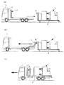
図4は実施例1の移動用変圧器をトラックに搭載する状態を示す側面図であり、(a)は搭載する前の状態、(b)は搭載している状態、(c)は搭載が完了して車両移動中の状態である。
このように構成した実施例1の移動用変圧器は、先ず運搬車両Tを移動用変圧器に近づける(図4(a)参照)。
次に、運搬車両Tからアームロール10の掛止具12をコンテナ2の係止構造8に近づけ、掛け止めたらこの掛止具12を運搬車両Tの前方ヘ移動させるように牽引する(図4(b)参照)。このときに、移動用変圧器は傾斜するので内部に変圧器油を充填したものでは漏洩のおそれがある。そこで、実施例1ではガス絶縁式の移動用変圧器が好ましい。
最後に、移動用変圧器をコンテナ2ごと運搬車両Tに搭載したらコンテナ2と運搬車両Tとを強固に固定する。その状態で運搬車両Tを目的地へ移動させる(図4(c)参照)。運搬車両Tが目的地に到着したら、上述した手順と逆の手順で移動用変圧器を降ろして設置する。
FIG. 4 is a side view showing a state where the moving transformer of the first embodiment is mounted on a truck. (A) is a state before mounting, (b) is a mounting state, and (c) is a mounting state. It is in a state where the vehicle is moving after completion.
The moving transformer according to the first embodiment configured as described above first brings the transport vehicle T closer to the moving transformer (see FIG. 4A).
Next, the hook 12 of the
Finally, when the transfer transformer is mounted on the transport vehicle T together with the
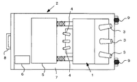
図5は実施例2の移動用変圧器を示す側面図である。
実施例2の移動用変圧器は、変圧器本体1を載せる略長方形状の板材のコンテナ台座7と、コンテナ台座7の前方側と後方側にそれぞれ設けた、昇降自在になる昇降装置13と、各昇降装置13の下端に取り付けた車輪14とを備えたものである。実施例2の移動用変圧器では、変圧器本体1を常時水平に維持しながら上下動させることができ、変圧器本体1を傾斜させることがないので絶縁油が漏洩することがない。
FIG. 5 is a side view showing the moving transformer of the second embodiment.
The moving transformer of the second embodiment includes a
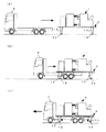
図6は実施例2の移動用変圧器をトラックに搭載する状態を示す側面図であり、(a)は移動用変圧器に車両を近づける状態、(b)は搭載している状態、(c)は搭載が完了して車両移動中の状態である。
このように構成した実施例2の移動用変圧器は、図6に示すように、先ず運搬車両Tを移動用変圧器に近づける(図6(a)参照)。更に、運搬車両Tをコンテナ2の下部にまで進入させる(図6(b)参照)。
次に、移動用変圧器をコンテナ2ごと運搬車両Tに搭載したら、コンテナ2と運搬車両Tとを強固に固定し、更に、車輪14の昇降装置13を縮めて搭載が完了する。その状態で目的地に移動する(図6(c)参照)。運搬車両Tが目的地に到着したら、上述した状態と逆の手順で移動用変圧器を降ろして設置する。
6A and 6B are side views showing a state in which the moving transformer according to the second embodiment is mounted on a truck. FIG. 6A is a state in which the vehicle is brought close to the moving transformer, FIG. 6B is a mounted state, and FIG. ) Is a state where the vehicle is moving after the mounting is completed.
As shown in FIG. 6, the moving transformer according to the second embodiment configured as described above first brings the transport vehicle T close to the moving transformer (see FIG. 6A). Further, the transport vehicle T is advanced to the lower part of the container 2 (see FIG. 6B).
Next, when the transfer transformer and the
なお、本発明は、移動用変圧器に、移動変圧器を運搬車両Tに着脱自在に構成することで、移動用変圧器を簡単にトラック等の運搬車両Tに搭載することができ、かつその移動用変圧器を必要な場所に容易に設置できれば、上述した発明の実施の形態に限定されず、本発明の要旨を逸脱しない範囲で種々変更できることは勿論である。 In the present invention, the mobile transformer can be easily mounted on the transport vehicle T such as a truck by configuring the mobile transformer so as to be detachable from the transport vehicle T. Of course, as long as the transformer for movement can be easily installed at a necessary place, the present invention is not limited to the embodiment of the invention described above, and various modifications can be made without departing from the gist of the invention.
本発明の移動用変圧器は、工夫したコンテナの上に変圧器を載置したものを車両を脱着自在にして運搬できるものであれば、コンテナの上に載置するものは変圧器以外のものにも利用することができる。 If the transformer for movement of this invention can carry the thing which mounted the transformer on the container which was devised and can make a vehicle detachable, what is mounted on a container is something other than a transformer. Can also be used.
1 変圧器本体
2 コンテナ
3 第一ブッシング
4 第二ブッシング
5 放熱器
7 コンテナ台座
8 係止構造
9 案内車輪
11 支持脚
13 昇降装置
14 車輪
T 運搬車両
DESCRIPTION OF
Claims (3)
鉄心に巻線を巻装し、該巻線を収容する本体タンクと、該本体タンクの外部へ該巻線の端子を引き出すブッシング(3,4)と、該本体タンク内を冷却する放熱器(5)とから成る変圧器本体(1)と、
前記変圧器本体(1)を載せる略長方形状の板材のコンテナ台座(7)と、該コンテナ台座(7)の一側に前記運搬車両(T)の荷台に牽引して積載する際に掛け止める係止構造(8)と、該コンテナ台座(7)の後方側に案内車輪(9)をそれぞれ具備したコンテナ(2)と、を備えた、ことを特徴とする移動用変圧器。 A transfer transformer that can be loaded and moved on a transport vehicle (T),
Winding is wound around an iron core, a main body tank that accommodates the winding, a bushing (3, 4) that pulls out the terminal of the winding to the outside of the main body tank, and a radiator that cools the inside of the main body tank ( 5) a transformer body (1) comprising:
A container base (7) of a substantially rectangular plate material on which the transformer main body (1) is placed, and hooked on one side of the container base (7) when being pulled and loaded on the carrier of the transport vehicle (T) A moving transformer comprising: a locking structure (8); and a container (2) provided with guide wheels (9) on the rear side of the container base (7).
鉄心に巻線を巻装し、該巻線を収容する本体タンクと、該本体タンク外部へ該巻線の端子を引き出すブッシング(3,4)と、該本体タンク内を冷却する放熱器(5)とから成る変圧器本体(1)と、
前記変圧器本体(1)を載せる略長方形状の板材のコンテナ台座(7)と、
前記コンテナ台座(7)の前方側と後方側にそれぞれ設けた、昇降自在になる昇降装置(13)と、
各昇降装置(13)の下端に取り付けた車輪(14)と、を備えた、ことを特徴とする移動用変圧器。 A transfer transformer (1) that can be loaded on a transport vehicle (T) and moved.
Winding is wound around an iron core, a main body tank for accommodating the winding, a bushing (3, 4) for pulling out terminals of the winding to the outside of the main body tank, and a radiator (5) for cooling the inside of the main body tank Transformer body (1) consisting of
A container base (7) of a substantially rectangular plate material on which the transformer body (1) is placed;
An elevating device (13) which is provided on the front side and the rear side of the container pedestal (7), and can be raised and lowered;
A moving transformer comprising: a wheel (14) attached to a lower end of each lifting device (13).
Priority Applications (1)
| Application Number | Priority Date | Filing Date | Title |
|---|---|---|---|
| JP2008042421A JP4919985B2 (en) | 2008-02-25 | 2008-02-25 | Transformer for movement |
Applications Claiming Priority (1)
| Application Number | Priority Date | Filing Date | Title |
|---|---|---|---|
| JP2008042421A JP4919985B2 (en) | 2008-02-25 | 2008-02-25 | Transformer for movement |
Publications (2)
| Publication Number | Publication Date |
|---|---|
| JP2009200375A true JP2009200375A (en) | 2009-09-03 |
| JP4919985B2 JP4919985B2 (en) | 2012-04-18 |
Family
ID=41143538
Family Applications (1)
| Application Number | Title | Priority Date | Filing Date |
|---|---|---|---|
| JP2008042421A Expired - Fee Related JP4919985B2 (en) | 2008-02-25 | 2008-02-25 | Transformer for movement |
Country Status (1)
| Country | Link |
|---|---|
| JP (1) | JP4919985B2 (en) |
Cited By (3)
| Publication number | Priority date | Publication date | Assignee | Title |
|---|---|---|---|---|
| KR101198950B1 (en) * | 2010-03-18 | 2012-11-08 | 서울전력주식회사 | Transformer for the pest control apparatus |
| CN106876095A (en) * | 2017-03-23 | 2017-06-20 | 广东电网有限责任公司江门供电局 | Meet the 110Kv/40MVA phase shifting transformer cars of the listed movement requirement of road |
| CN108584680A (en) * | 2018-06-29 | 2018-09-28 | 国网上海市电力公司 | A kind of hanging apparatus of transformer substation reactor iron core |
Citations (3)
| Publication number | Priority date | Publication date | Assignee | Title |
|---|---|---|---|---|
| JPS60181116A (en) * | 1984-02-02 | 1985-09-14 | バイエル・アクチエンゲゼルシヤフト | Manufacture of polyurea elastomer and elastomer having idealized segment structure corresponding to same |
| JPH02135536A (en) * | 1988-08-23 | 1990-05-24 | Internatl Business Mach Corp <Ibm> | Check point retrial mechanism |
| JP2000134729A (en) * | 1998-10-23 | 2000-05-12 | Koken:Kk | Self-lifting mobile apparatus installation/removal method, self-lifting generating method and the self- lifting mobile apparatus |
-
2008
- 2008-02-25 JP JP2008042421A patent/JP4919985B2/en not_active Expired - Fee Related
Patent Citations (3)
| Publication number | Priority date | Publication date | Assignee | Title |
|---|---|---|---|---|
| JPS60181116A (en) * | 1984-02-02 | 1985-09-14 | バイエル・アクチエンゲゼルシヤフト | Manufacture of polyurea elastomer and elastomer having idealized segment structure corresponding to same |
| JPH02135536A (en) * | 1988-08-23 | 1990-05-24 | Internatl Business Mach Corp <Ibm> | Check point retrial mechanism |
| JP2000134729A (en) * | 1998-10-23 | 2000-05-12 | Koken:Kk | Self-lifting mobile apparatus installation/removal method, self-lifting generating method and the self- lifting mobile apparatus |
Cited By (3)
| Publication number | Priority date | Publication date | Assignee | Title |
|---|---|---|---|---|
| KR101198950B1 (en) * | 2010-03-18 | 2012-11-08 | 서울전력주식회사 | Transformer for the pest control apparatus |
| CN106876095A (en) * | 2017-03-23 | 2017-06-20 | 广东电网有限责任公司江门供电局 | Meet the 110Kv/40MVA phase shifting transformer cars of the listed movement requirement of road |
| CN108584680A (en) * | 2018-06-29 | 2018-09-28 | 国网上海市电力公司 | A kind of hanging apparatus of transformer substation reactor iron core |
Also Published As
| Publication number | Publication date |
|---|---|
| JP4919985B2 (en) | 2012-04-18 |
Similar Documents
| Publication | Publication Date | Title |
|---|---|---|
| JP3056719B2 (en) | Self-lifting mobile equipment installation and removal method, self-lifting power generation method, and self-lifting mobile equipment | |
| CN103754148A (en) | Full-automatic extra-high voltage test vehicle | |
| CN103600680A (en) | Alternating current withstand voltage vehicle-mounted testing platform for 750kV ultrahigh voltage equipment | |
| JP4919985B2 (en) | Transformer for movement | |
| JP2009064936A (en) | Transformer transport assembly method and U-shaped iron core assembly apparatus | |
| JP4966246B2 (en) | Gas-insulated switchgear for movement and its field operation method | |
| CN203601100U (en) | Alternating current voltage-withstanding vehicle-mounted test platform for 750kv supervoltage equipment | |
| JP2011142764A (en) | Mobile transformer carrier | |
| CN206163970U (en) | 110kV electric pressure, main varactor volume 50MVA's mobile substation | |
| CN113526298B (en) | Transport vehicle for building and construction method thereof | |
| WO2010113704A1 (en) | Container crane | |
| JP6143103B2 (en) | Curtain wall mounting method and curtain wall lifting box used therefor | |
| JP6344778B2 (en) | Material attachment unit for overhead wire bypass construction and carriage for transporting material attachment unit for overhead wire bypass construction | |
| WO2014195981A1 (en) | Mobile station for telecommunicacions | |
| JP2013103712A (en) | Movable rack apparatus for to be loaded with wire coil or the like, and motor truck or trailer | |
| JP5781344B2 (en) | Transformer device for movement | |
| CN105356348A (en) | Power transformation vehicle | |
| JP4661010B2 (en) | Distribution substation | |
| JPH05135957A (en) | Method for assembling disassemble transportation induction apparatus | |
| JPH0562838A (en) | Disassembled transportation type single-phase transformer | |
| JPH07220958A (en) | Utility pole-mounted construction transformer | |
| JP4891733B2 (en) | Electrical equipment installation method and electrical equipment removal method | |
| CN105438632A (en) | Auxiliary support for box transport | |
| JP5225402B2 (en) | Transformer for movement | |
| KR101639610B1 (en) | Transformers and Transfer Method of Offshore Structures |
Legal Events
| Date | Code | Title | Description |
|---|---|---|---|
| A621 | Written request for application examination |
Free format text: JAPANESE INTERMEDIATE CODE: A621 Effective date: 20101214 |
|
| A131 | Notification of reasons for refusal |
Free format text: JAPANESE INTERMEDIATE CODE: A131 Effective date: 20111118 |
|
| A521 | Request for written amendment filed |
Free format text: JAPANESE INTERMEDIATE CODE: A523 Effective date: 20111221 |
|
| RD02 | Notification of acceptance of power of attorney |
Free format text: JAPANESE INTERMEDIATE CODE: A7422 Effective date: 20111221 |
|
| TRDD | Decision of grant or rejection written | ||
| A01 | Written decision to grant a patent or to grant a registration (utility model) |
Free format text: JAPANESE INTERMEDIATE CODE: A01 Effective date: 20120125 |
|
| A01 | Written decision to grant a patent or to grant a registration (utility model) |
Free format text: JAPANESE INTERMEDIATE CODE: A01 |
|
| A61 | First payment of annual fees (during grant procedure) |
Free format text: JAPANESE INTERMEDIATE CODE: A61 Effective date: 20120131 |
|
| R150 | Certificate of patent or registration of utility model |
Ref document number: 4919985 Country of ref document: JP Free format text: JAPANESE INTERMEDIATE CODE: R150 Free format text: JAPANESE INTERMEDIATE CODE: R150 |
|
| FPAY | Renewal fee payment (event date is renewal date of database) |
Free format text: PAYMENT UNTIL: 20150210 Year of fee payment: 3 |
|
| FPAY | Renewal fee payment (event date is renewal date of database) |
Free format text: PAYMENT UNTIL: 20150210 Year of fee payment: 3 |
|
| R250 | Receipt of annual fees |
Free format text: JAPANESE INTERMEDIATE CODE: R250 |
|
| R250 | Receipt of annual fees |
Free format text: JAPANESE INTERMEDIATE CODE: R250 |
|
| R250 | Receipt of annual fees |
Free format text: JAPANESE INTERMEDIATE CODE: R250 |
|
| R250 | Receipt of annual fees |
Free format text: JAPANESE INTERMEDIATE CODE: R250 |
|
| R250 | Receipt of annual fees |
Free format text: JAPANESE INTERMEDIATE CODE: R250 |
|
| R250 | Receipt of annual fees |
Free format text: JAPANESE INTERMEDIATE CODE: R250 |
|
| LAPS | Cancellation because of no payment of annual fees |