JP2009199751A - Fuel cell system, and method of controlling the same - Google Patents
Fuel cell system, and method of controlling the same Download PDFInfo
- Publication number
- JP2009199751A JP2009199751A JP2008037268A JP2008037268A JP2009199751A JP 2009199751 A JP2009199751 A JP 2009199751A JP 2008037268 A JP2008037268 A JP 2008037268A JP 2008037268 A JP2008037268 A JP 2008037268A JP 2009199751 A JP2009199751 A JP 2009199751A
- Authority
- JP
- Japan
- Prior art keywords
- fuel cell
- electrode assembly
- temperature
- membrane electrode
- separator
- Prior art date
- Legal status (The legal status is an assumption and is not a legal conclusion. Google has not performed a legal analysis and makes no representation as to the accuracy of the status listed.)
- Pending
Links
Images


Classifications
-
- H—ELECTRICITY
- H01—ELECTRIC ELEMENTS
- H01M—PROCESSES OR MEANS, e.g. BATTERIES, FOR THE DIRECT CONVERSION OF CHEMICAL ENERGY INTO ELECTRICAL ENERGY
- H01M8/00—Fuel cells; Manufacture thereof
- H01M8/04—Auxiliary arrangements, e.g. for control of pressure or for circulation of fluids
- H01M8/04223—Auxiliary arrangements, e.g. for control of pressure or for circulation of fluids during start-up or shut-down; Depolarisation or activation, e.g. purging; Means for short-circuiting defective fuel cells
- H01M8/04268—Heating of fuel cells during the start-up of the fuel cells
-
- H—ELECTRICITY
- H01—ELECTRIC ELEMENTS
- H01M—PROCESSES OR MEANS, e.g. BATTERIES, FOR THE DIRECT CONVERSION OF CHEMICAL ENERGY INTO ELECTRICAL ENERGY
- H01M8/00—Fuel cells; Manufacture thereof
- H01M8/02—Details
- H01M8/0202—Collectors; Separators, e.g. bipolar separators; Interconnectors
- H01M8/0267—Collectors; Separators, e.g. bipolar separators; Interconnectors having heating or cooling means, e.g. heaters or coolant flow channels
-
- H—ELECTRICITY
- H01—ELECTRIC ELEMENTS
- H01M—PROCESSES OR MEANS, e.g. BATTERIES, FOR THE DIRECT CONVERSION OF CHEMICAL ENERGY INTO ELECTRICAL ENERGY
- H01M8/00—Fuel cells; Manufacture thereof
- H01M8/04—Auxiliary arrangements, e.g. for control of pressure or for circulation of fluids
- H01M8/04007—Auxiliary arrangements, e.g. for control of pressure or for circulation of fluids related to heat exchange
- H01M8/04029—Heat exchange using liquids
-
- H—ELECTRICITY
- H01—ELECTRIC ELEMENTS
- H01M—PROCESSES OR MEANS, e.g. BATTERIES, FOR THE DIRECT CONVERSION OF CHEMICAL ENERGY INTO ELECTRICAL ENERGY
- H01M8/00—Fuel cells; Manufacture thereof
- H01M8/04—Auxiliary arrangements, e.g. for control of pressure or for circulation of fluids
- H01M8/04007—Auxiliary arrangements, e.g. for control of pressure or for circulation of fluids related to heat exchange
- H01M8/04067—Heat exchange or temperature measuring elements, thermal insulation, e.g. heat pipes, heat pumps, fins
- H01M8/04074—Heat exchange unit structures specially adapted for fuel cell
-
- H—ELECTRICITY
- H01—ELECTRIC ELEMENTS
- H01M—PROCESSES OR MEANS, e.g. BATTERIES, FOR THE DIRECT CONVERSION OF CHEMICAL ENERGY INTO ELECTRICAL ENERGY
- H01M8/00—Fuel cells; Manufacture thereof
- H01M8/04—Auxiliary arrangements, e.g. for control of pressure or for circulation of fluids
- H01M8/04082—Arrangements for control of reactant parameters, e.g. pressure or concentration
- H01M8/04089—Arrangements for control of reactant parameters, e.g. pressure or concentration of gaseous reactants
- H01M8/04119—Arrangements for control of reactant parameters, e.g. pressure or concentration of gaseous reactants with simultaneous supply or evacuation of electrolyte; Humidifying or dehumidifying
- H01M8/04156—Arrangements for control of reactant parameters, e.g. pressure or concentration of gaseous reactants with simultaneous supply or evacuation of electrolyte; Humidifying or dehumidifying with product water removal
- H01M8/04179—Arrangements for control of reactant parameters, e.g. pressure or concentration of gaseous reactants with simultaneous supply or evacuation of electrolyte; Humidifying or dehumidifying with product water removal by purging or increasing flow or pressure of reactants
-
- H—ELECTRICITY
- H01—ELECTRIC ELEMENTS
- H01M—PROCESSES OR MEANS, e.g. BATTERIES, FOR THE DIRECT CONVERSION OF CHEMICAL ENERGY INTO ELECTRICAL ENERGY
- H01M8/00—Fuel cells; Manufacture thereof
- H01M8/04—Auxiliary arrangements, e.g. for control of pressure or for circulation of fluids
- H01M8/04223—Auxiliary arrangements, e.g. for control of pressure or for circulation of fluids during start-up or shut-down; Depolarisation or activation, e.g. purging; Means for short-circuiting defective fuel cells
- H01M8/04253—Means for solving freezing problems
-
- H—ELECTRICITY
- H01—ELECTRIC ELEMENTS
- H01M—PROCESSES OR MEANS, e.g. BATTERIES, FOR THE DIRECT CONVERSION OF CHEMICAL ENERGY INTO ELECTRICAL ENERGY
- H01M8/00—Fuel cells; Manufacture thereof
- H01M8/04—Auxiliary arrangements, e.g. for control of pressure or for circulation of fluids
- H01M8/04298—Processes for controlling fuel cells or fuel cell systems
- H01M8/043—Processes for controlling fuel cells or fuel cell systems applied during specific periods
-
- H—ELECTRICITY
- H01—ELECTRIC ELEMENTS
- H01M—PROCESSES OR MEANS, e.g. BATTERIES, FOR THE DIRECT CONVERSION OF CHEMICAL ENERGY INTO ELECTRICAL ENERGY
- H01M8/00—Fuel cells; Manufacture thereof
- H01M8/04—Auxiliary arrangements, e.g. for control of pressure or for circulation of fluids
- H01M8/04298—Processes for controlling fuel cells or fuel cell systems
- H01M8/04313—Processes for controlling fuel cells or fuel cell systems characterised by the detection or assessment of variables; characterised by the detection or assessment of failure or abnormal function
- H01M8/0432—Temperature; Ambient temperature
-
- H—ELECTRICITY
- H01—ELECTRIC ELEMENTS
- H01M—PROCESSES OR MEANS, e.g. BATTERIES, FOR THE DIRECT CONVERSION OF CHEMICAL ENERGY INTO ELECTRICAL ENERGY
- H01M8/00—Fuel cells; Manufacture thereof
- H01M8/04—Auxiliary arrangements, e.g. for control of pressure or for circulation of fluids
- H01M8/04298—Processes for controlling fuel cells or fuel cell systems
- H01M8/04694—Processes for controlling fuel cells or fuel cell systems characterised by variables to be controlled
- H01M8/04746—Pressure; Flow
- H01M8/04753—Pressure; Flow of fuel cell reactants
-
- H—ELECTRICITY
- H01—ELECTRIC ELEMENTS
- H01M—PROCESSES OR MEANS, e.g. BATTERIES, FOR THE DIRECT CONVERSION OF CHEMICAL ENERGY INTO ELECTRICAL ENERGY
- H01M8/00—Fuel cells; Manufacture thereof
- H01M8/24—Grouping of fuel cells, e.g. stacking of fuel cells
- H01M8/241—Grouping of fuel cells, e.g. stacking of fuel cells with solid or matrix-supported electrolytes
-
- H—ELECTRICITY
- H01—ELECTRIC ELEMENTS
- H01M—PROCESSES OR MEANS, e.g. BATTERIES, FOR THE DIRECT CONVERSION OF CHEMICAL ENERGY INTO ELECTRICAL ENERGY
- H01M8/00—Fuel cells; Manufacture thereof
- H01M8/24—Grouping of fuel cells, e.g. stacking of fuel cells
- H01M8/2457—Grouping of fuel cells, e.g. stacking of fuel cells with both reactants being gaseous or vaporised
-
- H—ELECTRICITY
- H01—ELECTRIC ELEMENTS
- H01M—PROCESSES OR MEANS, e.g. BATTERIES, FOR THE DIRECT CONVERSION OF CHEMICAL ENERGY INTO ELECTRICAL ENERGY
- H01M8/00—Fuel cells; Manufacture thereof
- H01M8/10—Fuel cells with solid electrolytes
- H01M2008/1095—Fuel cells with polymeric electrolytes
-
- Y—GENERAL TAGGING OF NEW TECHNOLOGICAL DEVELOPMENTS; GENERAL TAGGING OF CROSS-SECTIONAL TECHNOLOGIES SPANNING OVER SEVERAL SECTIONS OF THE IPC; TECHNICAL SUBJECTS COVERED BY FORMER USPC CROSS-REFERENCE ART COLLECTIONS [XRACs] AND DIGESTS
- Y02—TECHNOLOGIES OR APPLICATIONS FOR MITIGATION OR ADAPTATION AGAINST CLIMATE CHANGE
- Y02E—REDUCTION OF GREENHOUSE GAS [GHG] EMISSIONS, RELATED TO ENERGY GENERATION, TRANSMISSION OR DISTRIBUTION
- Y02E60/00—Enabling technologies; Technologies with a potential or indirect contribution to GHG emissions mitigation
- Y02E60/30—Hydrogen technology
- Y02E60/50—Fuel cells
Abstract
Description
本発明は、燃料電池システム、および、燃料電池システムの制御方法に関するものである。 The present invention relates to a fuel cell system and a control method for the fuel cell system.
従来、燃料ガス(例えば、水素)と酸化剤ガス(例えば、酸素)との電気化学反応によって発電する燃料電池がエネルギ源として注目されている。この燃料電池は、プロトン伝導性を有する電解質膜の両面に、それぞれ、アノード、および、カソードを接合してなる膜電極接合体を、セパレータによって挟持することによって構成される。そして、膜電極接合体のカソードでは、発電時に、カソード反応によって、水(生成水)が生成される。 Conventionally, a fuel cell that generates power by an electrochemical reaction between a fuel gas (for example, hydrogen) and an oxidant gas (for example, oxygen) has attracted attention as an energy source. This fuel cell is configured by sandwiching a membrane electrode assembly formed by joining an anode and a cathode on both sides of an electrolyte membrane having proton conductivity, with a separator. At the cathode of the membrane electrode assembly, water (generated water) is generated by the cathode reaction during power generation.
このような燃料電池を備える燃料電池システムでは、燃料電池による発電停止後に、燃料電池の温度が氷点下になると、膜電極接合体に含まれる生成水が凍結する。そして、この状態で燃料電池システムを始動すると、凍結した生成水によって、膜電極接合体のアノードへの燃料ガスの供給、および、カソードへの酸化剤ガスの供給が妨げられ、燃料電池の発電性能が低下する。 In a fuel cell system including such a fuel cell, when the temperature of the fuel cell becomes below freezing after power generation is stopped by the fuel cell, the generated water contained in the membrane electrode assembly is frozen. When the fuel cell system is started in this state, the supply of fuel gas to the anode of the membrane electrode assembly and the supply of oxidant gas to the cathode are hindered by the frozen generated water, and the power generation performance of the fuel cell Decreases.
そこで、従来、燃料電池システムにおいて、発電停止中の燃料電池の内部における生成水の凍結を抑制するための種々の技術が提案されている。 Therefore, conventionally, various techniques have been proposed in the fuel cell system for suppressing the freezing of generated water inside the fuel cell in which power generation is stopped.
しかし、上記特許文献に記載された技術では、燃料電池の内部に残留した生成水を燃料電池の外部に排出させる運転を行ったり、燃料電池の温度を凍結温度よりも高い温度に維持する運転を行ったりするため、これらの運転を行う際に、エネルギを消費し、燃料電池システムのエネルギ効率の低下を招く。 However, in the technique described in the above-mentioned patent document, an operation for discharging generated water remaining inside the fuel cell to the outside of the fuel cell, or an operation for maintaining the temperature of the fuel cell at a temperature higher than the freezing temperature is performed. Therefore, when performing these operations, energy is consumed, and the energy efficiency of the fuel cell system is reduced.
本発明は、上述の課題を解決するためになされたものであり、燃料電池を備える燃料電池システムにおいて、燃料電池システムのエネルギ効率の低下を抑制するとともに、低温始動性を向上させることを目的とする。 The present invention has been made to solve the above-described problems, and aims to improve low-temperature startability while suppressing a decrease in energy efficiency of the fuel cell system in a fuel cell system including a fuel cell. To do.
本発明は、上述の課題の少なくとも一部を解決するために以下の形態又は適用例として実現することが可能である。 The present invention can be realized as the following forms or application examples in order to solve at least a part of the above-described problems.
[適用例1]燃料電池システムであって、電解質膜の両面に、それぞれ、アノード、および、カソードを接合してなる膜電極接合体を、セパレータによって挟持した燃料電池と、前記アノードに燃料ガスを供給する燃料ガス供給部と、前記カソードに酸化剤ガスを供給する酸化剤ガス供給部と、前記燃料電池を冷却するための冷却媒体を、前記セパレータ内に形成された冷却媒体流路に循環させる冷却媒体循環部と、前記各部を制御する制御部と、を備え、前記制御部は、前記燃料電池による発電停止後に、発電中に前記燃料ガスと前記酸化剤ガスとの電気化学反応によって生成された生成水が、前記膜電極接合体において凍結すると予測された際に、前記燃料ガス供給部と、前記酸化剤ガス供給部と、前記冷却媒体循環部とのうちの少なくとも1つを起動して、前記膜電極接合体の温度が前記セパレータの温度よりも相対的に高くなるように、前記膜電極接合体と前記セパレータとの間に温度勾配を形成する温度勾配形成制御を行い、前記膜電極接合体と前記セパレータとの間に前記温度勾配が形成された後に、前記温度勾配形成制御を停止する、燃料電池システム。 [Application Example 1] A fuel cell system, in which a membrane electrode assembly formed by joining an anode and a cathode on both surfaces of an electrolyte membrane is sandwiched by separators, and fuel gas is fed to the anode A fuel gas supply unit for supplying, an oxidant gas supply unit for supplying an oxidant gas to the cathode, and a cooling medium for cooling the fuel cell are circulated in a cooling medium flow path formed in the separator. A cooling medium circulation unit; and a control unit that controls each of the units. The control unit is generated by an electrochemical reaction between the fuel gas and the oxidant gas during power generation after power generation is stopped by the fuel cell. Of the fuel gas supply unit, the oxidant gas supply unit, and the cooling medium circulation unit when the generated water is predicted to freeze in the membrane electrode assembly. Forming a temperature gradient between the membrane electrode assembly and the separator so that the temperature of the membrane electrode assembly is relatively higher than the temperature of the separator. A fuel cell system that performs control and stops the temperature gradient formation control after the temperature gradient is formed between the membrane electrode assembly and the separator.
適用例1の燃料電池システムでは、燃料電池による発電停止後に、発電中に燃料ガスと酸化剤ガスとの電気化学反応によって生成された生成水が、膜電極接合体において凍結すると予測された際に、燃料ガス供給部と、酸化剤ガス供給部と、前記冷却媒体循環部とのうちの少なくとも1つを起動して、膜電極接合体の温度が、セパレータの温度よりも相対的に高くなるように、膜電極接合体とセパレータとの間に温度勾配を形成する温度勾配形成制御を行う。こうすることによって、膜電極接合体とセパレータとの間に蒸気圧勾配が生じ、膜電極接合体に含まれる生成水に、蒸気圧が高い膜電極接合体側から蒸気圧が低いセパレータ側へ移動する駆動力が作用する。したがって、膜電極接合体に含まれる生成水を、セパレータ側に移動させ、氷点下の低温環境下における膜電極接合体での生成水の凍結を抑制することができる。この結果、燃料電池システムの低温始動性を向上させることができる。 In the fuel cell system of Application Example 1, when the generated water generated by the electrochemical reaction between the fuel gas and the oxidant gas during power generation is predicted to freeze in the membrane electrode assembly after power generation by the fuel cell is stopped. Activating at least one of the fuel gas supply unit, the oxidant gas supply unit, and the cooling medium circulation unit so that the temperature of the membrane electrode assembly is relatively higher than the temperature of the separator In addition, temperature gradient formation control for forming a temperature gradient between the membrane electrode assembly and the separator is performed. By doing so, a vapor pressure gradient is generated between the membrane electrode assembly and the separator, and the generated water contained in the membrane electrode assembly moves from the membrane electrode assembly side having a high vapor pressure to the separator side having a low vapor pressure. Driving force acts. Therefore, the produced water contained in the membrane electrode assembly can be moved to the separator side, and freezing of the produced water in the membrane electrode assembly in a low temperature environment below freezing can be suppressed. As a result, the low temperature startability of the fuel cell system can be improved.
また、上記温度勾配形成制御は、膜電極接合体とセパレータとの間に、所望の温度勾配が形成されるまでの期間のみ行われ、その温度勾配が形成された後には速やかに停止される。したがって、先に説明した従来技術、すなわち、燃料電池の内部に残留した生成水を燃料電池の外部に排出させる運転や、燃料電池の温度を凍結温度よりも高い温度に維持する運転と比較して、燃料電池システムのエネルギ効率の低下を抑制することができる。 The temperature gradient formation control is performed only during a period until a desired temperature gradient is formed between the membrane electrode assembly and the separator, and is quickly stopped after the temperature gradient is formed. Therefore, compared with the prior art described above, that is, the operation of discharging the generated water remaining inside the fuel cell to the outside of the fuel cell and the operation of maintaining the temperature of the fuel cell at a temperature higher than the freezing temperature. And the fall of the energy efficiency of a fuel cell system can be controlled.
なお、上記生成水が、膜電極接合体において凍結するか否かの予測は、種々の方法を適用可能である。例えば、燃料電池に温度センサを設けて、この温度センサによって、燃料電池の温度を適宜検出し、検出された温度や、温度の変化率に基づいて、上記生成水が膜電極接合体において凍結するか否かを判断するようにすることができる。また、燃料電池の外部の環境温度、環境温度の変化率、冷却媒体の温度、冷却媒体の温度の変化率の少なくとも一部に基づいて、上記生成水が膜電極接合体において凍結するか否かを判断するようにしてもよい。 Various methods can be applied to predict whether the generated water will freeze in the membrane electrode assembly. For example, a temperature sensor is provided in the fuel cell, the temperature of the fuel cell is appropriately detected by this temperature sensor, and the generated water is frozen in the membrane electrode assembly based on the detected temperature and the rate of change of temperature. It can be determined whether or not. Whether or not the generated water is frozen in the membrane electrode assembly based on at least a part of the environmental temperature outside the fuel cell, the environmental temperature change rate, the cooling medium temperature, and the cooling medium temperature change rate. May be determined.
[適用例2]適用例1記載の燃料電池システムであって、前記制御部は、前記温度勾配形成制御として、前記燃料ガス供給部、および、前記酸化剤ガス供給部を起動して、前記燃料電池による発電を行うことによって、前記膜電極接合体の温度を、前記セパレータの温度よりも高くする、燃料電池システム。 Application Example 2 In the fuel cell system according to Application Example 1, the control unit activates the fuel gas supply unit and the oxidant gas supply unit as the temperature gradient formation control, and the fuel A fuel cell system in which the temperature of the membrane electrode assembly is made higher than the temperature of the separator by performing power generation using a battery.
適用例2の燃料電池システムによって、膜電極接合体の温度を、セパレータの温度よりも高くすることができる。なお、温度勾配形成制御における発電は、膜電極接合体とセパレータとの間に温度勾配が形成されればよいため、定常発電よりも微弱な発電でよい。 With the fuel cell system of Application Example 2, the temperature of the membrane electrode assembly can be made higher than the temperature of the separator. Note that the power generation in the temperature gradient formation control only needs to generate a temperature gradient between the membrane electrode assembly and the separator, and therefore may be weaker than the steady power generation.
[適用例3]適用例1記載の燃料電池システムであって、前記制御部は、前記温度勾配形成制御として、前記冷却媒体循環部を起動して、前記セパレータに前記冷却媒体を循環させることによって、前記セパレータの温度を、前記膜電極接合体の温度よりも低くする、燃料電池システム。 [Application Example 3] The fuel cell system according to Application Example 1, wherein the control unit starts the cooling medium circulation unit and causes the separator to circulate the cooling medium as the temperature gradient formation control. The fuel cell system, wherein the temperature of the separator is lower than the temperature of the membrane electrode assembly.
適用例3の燃料電池システムによって、膜電極接合体の温度を、セパレータの温度よりも高くすることができる。 With the fuel cell system of Application Example 3, the temperature of the membrane electrode assembly can be made higher than the temperature of the separator.
[適用例4]適用例1記載の燃料電池システムであって、前記アノード、および、カソードは、前記燃料ガスと前記酸化剤ガスとの反応を促進するための触媒を含んでおり、前記燃料電池システムは、さらに、前記アノード、および、前記カソードの少なくとも一方に、前記燃料ガスと前記酸化剤ガスとの混合ガスを供給する混合ガス供給部を備え、前記制御部は、前記温度勾配形成制御として、前記混合ガス供給部を起動して、前記触媒で前記混合ガスを燃焼させることによって、前記膜電極接合体の温度を、前記セパレータの温度よりも高くする、燃料電池システム。 Application Example 4 The fuel cell system according to Application Example 1, wherein the anode and the cathode include a catalyst for promoting a reaction between the fuel gas and the oxidant gas, and the fuel cell. The system further includes a mixed gas supply unit that supplies a mixed gas of the fuel gas and the oxidant gas to at least one of the anode and the cathode, and the control unit performs the temperature gradient formation control. The fuel cell system is configured such that the temperature of the membrane electrode assembly is made higher than the temperature of the separator by starting the mixed gas supply unit and burning the mixed gas with the catalyst.
適用例4の燃料電池システムによって、膜電極接合体の温度を、セパレータの温度よりも高くすることができる。 With the fuel cell system of Application Example 4, the temperature of the membrane electrode assembly can be made higher than the temperature of the separator.
本発明は、上述した種々の特徴の一部を、適宜、組み合わせて構成することもできる。また、本発明は、上述の燃料電池システムとしての構成の他、燃料電池システムの制御方法の発明として構成することもできる。また、これらを実現するコンピュータプログラム、およびそのプログラムを記録した記録媒体、そのプログラムを含み搬送波内に具現化されたデータ信号など種々の態様で実現することが可能である。なお、それぞれの態様において、先に示した種々の付加的要素を適用することが可能である。 The present invention can also be configured by appropriately combining some of the various features described above. Further, the present invention can be configured as an invention of a control method for a fuel cell system in addition to the above-described configuration as a fuel cell system. Further, the present invention can be realized in various modes such as a computer program that realizes these, a recording medium that records the program, and a data signal that includes the program and is embodied in a carrier wave. In addition, in each aspect, it is possible to apply the various additional elements shown above.
本発明をコンピュータプログラムまたはそのプログラムを記録した記録媒体等として構成する場合には、燃料電池システムの動作を制御するプログラム全体として構成するものとしてもよいし、本発明の機能を果たす部分のみを構成するものとしてもよい。また、記録媒体としては、フレキシブルディスクやCD−ROM、DVD−ROM、光磁気ディスク、ICカード、ROMカートリッジ、パンチカード、バーコードなどの符号が印刷された印刷物、コンピュータの内部記憶装置(RAMやROMなどのメモリ)および外部記憶装置などコンピュータが読み取り可能な種々の媒体を利用できる。 When the present invention is configured as a computer program or a recording medium storing the program, the entire program for controlling the operation of the fuel cell system may be configured, or only the portion that performs the function of the present invention is configured. It is good also as what to do. The recording medium includes a flexible disk, a CD-ROM, a DVD-ROM, a magneto-optical disk, an IC card, a ROM cartridge, a punch card, a printed matter on which a code such as a barcode is printed, a computer internal storage device (RAM or Various types of computer-readable media such as a memory such as a ROM and an external storage device can be used.
以下、本発明の実施の形態について、実施例に基づき説明する。
A.第1実施例:
A1.燃料電池システムの構成:
図1は、本発明の第1実施例としての燃料電池システム1000の概略構成を示す説明図である。
Hereinafter, embodiments of the present invention will be described based on examples.
A. First embodiment:
A1. Configuration of fuel cell system:
FIG. 1 is an explanatory diagram showing a schematic configuration of a
燃料電池スタック100は、水素と酸素との電気化学反応によって発電する単セル40を、複数積層させたスタック構造を有している。各単セル40は、概ね、プロトン伝導性を有する電解質膜の両面に、それぞれアノード、および、カソードを接合した膜電極接合体を、セパレータによって挟持した構成となっている。アノード、および、カソードは、それぞれ、電解質膜の各表面に接合された触媒層と、この触媒層の表面に接合されたガス拡散層とを備えている。本実施例では、電解質膜として、ナフィオン(登録商標)等の固体高分子膜を用いるものとした。電解質膜として、固体酸化物等、他の電解質膜を用いるものとしてもよい。各セパレータには、アノードに供給すべき燃料ガスとしての水素の流路や、カソードに供給すべき酸化剤ガスとしての空気の流路や、冷却媒体(水、エチレングリコール等)の流路が形成されている。なお、単セル40の積層数は、燃料電池スタック100に要求される出力に応じて任意に設定可能である。
The
燃料電池スタック100は、一端から、エンドプレート10a、絶縁板20a、集電板30a、複数の単セル40、集電板30b、絶縁板20b、エンドプレート10bの順に積層することによって構成されている。これらには、燃料電池スタック100内に、水素や、空気や、冷却媒体を流すための供給口や、排出口が設けられている。また、燃料電池スタック100内部には、水素や、空気や、冷却媒体を、それぞれ各単セル40に分配して供給するための供給マニホールド(水素供給マニホールド、空気供給マニホールド、冷却媒体供給マニホールド)や、各単セル40のアノードおよびカソードからそれぞれ排出されるアノードオフガスおよびカソードオフガスや、冷却媒体を集合させて燃料電池スタック100の外部に排出するための排出マニホールド(アノードオフガス排出マニホールド、カソードオフガス排出マニホールド、冷却媒体排出マニホールド)が形成されている。
The
また、燃料電池スタック100には、単セル40の温度を検出するための温度センサ90が設けられている。図示するように、本実施例では、温度センサ90は、放熱によって温度が低下しやすい、複数の単セル40の積層方向の端部に配置された単セル40に設けられているものとした。
Further, the
エンドプレート10a,10bは、剛性を確保するため、鋼等の金属によって形成されている。絶縁板20a,20bは、ゴムや、樹脂等の絶縁性部材によって形成されている。集電板30a,30bは、緻密質カーボンや、銅板などのガス不透過な導電性部材によって形成されている。集電板30a,30bには、それぞれ図示しない出力端子が設けられており、燃料電池スタック100で発電した電力を出力可能となっている。
The
なお、図示は省略しているが、燃料電池スタック100は、スタック構造のいずれかの箇所における接触抵抗の増加等による電池性能の低下を抑制したり、ガスの漏洩を抑制したりするために、スタック構造の積層方向に、所定の締結荷重が加えられた状態で、締結部材によって締結されている。
In addition, although illustration is abbreviate | omitted, in order for the
燃料電池スタック100のアノードには、配管53を介して、高圧水素を貯蔵した水素タンク50から、燃料ガスとしての水素が供給される。水素タンク50の代わりに、アルコール、炭化水素、アルデヒドなどを原料とする改質反応によって水素リッチなガスを生成し、アノードに供給するものとしてもよい。
Hydrogen as fuel gas is supplied to the anode of the
水素タンク50に貯蔵された高圧水素は、水素タンク50の出口に設けられたシャットバルブ51、レギュレータ52によって圧力、および、供給量が調整されて、水素供給マニホールドを介して、各単セル40のアノードに供給される。各単セル40から排出されるアノードオフガスは、アノードオフガス排出マニホールドに接続された排出配管56を介して、燃料電池スタック100の外部に排出することができる。なお、アノードオフガスを燃料電池スタック100の外部に排出する際には、アノードオフガスに含まれる水素は、図示しない希釈器等によって処理される。
The high-pressure hydrogen stored in the
また、配管53、および、排出配管56には、アノードオフガスを配管53に再循環させるための循環配管54が接続されている。そして、排出配管56の循環配管54との接続部の下流側には、排気バルブ57が配設されている。また、循環配管54には、ポンプ55が配設されている。ポンプ55、および、排気バルブ57の駆動を制御することによって、アノードオフガスを外部に排出するか、配管53に循環させるかを適宜切り換えることができる。アノードオフガスを配管53に再循環させることによって、アノードオフガスに含まれる未消費の水素を効率よく利用することができる。
Further, a
燃料電池スタック100のカソードには、配管61を介して、コンプレッサ60によって圧縮された圧縮空気が、酸素を含有した酸化剤ガスとして供給される。そして、この圧縮空気は、配管61に接続された空気供給マニホールドを介して、各単セル40のカソードに供給される。各単セル40のカソードから排出されるカソードオフガスは、カソードオフガス排出マニホールドに接続された排出配管62を介して、燃料電池スタック100の外部に排出される。排出配管62からは、カソードオフガスとともに、燃料電池スタック100のカソードで、水素と酸素との電気化学反応によって生成された生成水も排出される。
Compressed air compressed by the
燃料電池スタック100は、上述した電気化学反応によって発熱するため、燃料電池スタック100には、燃料電池スタック100を冷却するための冷却媒体も供給される。この冷却媒体は、ポンプ70によって、配管72を流れ、ラジエータ71によって冷却されて、燃料電池スタック100に供給される。
Since the
なお、図示は省略しているが、氷点下の低温環境下において、燃料電池スタック100の内部における生成水の凍結を抑制するために、燃料電池スタック100は、断熱性を有するケースに収納されている。
Although not shown, the
燃料電池システム1000の運転は、制御ユニット80によって制御される。制御ユニット80は、内部にCPU、RAM、ROM、タイマなどを備えるマイクロコンピュータとして構成されており、ROMに記憶されたプログラムに従って、例えば、各種バルブや、ポンプの駆動等、システムの運転を制御する。また、本実施例の燃料電池システム1000では、制御ユニット80は、燃料電池スタック100による発電停止後に、以下に説明する運転制御処理を行う。
The operation of the
A2.発電停止後の運転制御処理:
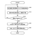
図2は、第1実施例における燃料電池スタック100による発電停止後の運転制御処理の流れを示すフローチャートである。この処理は、制御ユニット80のCPUが実行する処理である。
A2. Operation control processing after stopping power generation:
FIG. 2 is a flowchart showing a flow of operation control processing after power generation is stopped by the
まず、CPUは、温度センサ90によって、所定周期で燃料電池スタック100の温度を検出する(ステップS100)。本実施例では、1時間周期で燃料電池スタック100の温度を検出するものとした。なお、上記所定周期は、任意に設定可能である。また、燃料電池スタック100の温度の検出周期を、温度センサ90によって検出された温度に応じて変化させるようにしてもよい。例えば、発電停止後の初期には、燃料電池スタック100の温度の検出周期を1時間とし、燃料電池スタック100の温度が、所定温度(例えば、10(℃))以下になったときに、燃料電池スタック100の温度の検出周期を5分とするようにしてもよい。
First, the CPU detects the temperature of the
そして、CPUは、燃料電池スタック100の温度の変化率(低下率)を算出し、燃料電池スタック100の温度と、燃料電池スタック100の温度の変化率とに基づいて、燃料電池スタック100内の膜電極接合体における生成水の凍結を予測する(ステップS110)。そして、膜電極接合体において、生成水が凍結しないと判断された場合には(ステップS120:NO)、ステップS100に戻る。なお、燃料電池スタック100による発電停止後、相当時間経過後は、燃料電池スタック100を構成する膜電極接合体とセパレータの温度はほぼ等しい。
Then, the CPU calculates the rate of change (decrease rate) of the temperature of the
一方、膜電極接合体において、生成水が凍結する判断された場合には(ステップS120:YES)、CPUは、膜電極接合体の温度が氷点下になる直前のタイミングで、シャットバルブ51、レギュレータ52、排気バルブ57を開弁するとともに、コンプレッサ60を起動して、膜電極接合体のアノード、および、カソードに、それぞれ、水素、および、空気を供給し(ステップS130)、所定期間、燃料電池スタック100によって、定常発電よりも微弱な発電を行い、この発電による膜電極接合体の発熱によって、膜電極接合体とセパレータとの間に、温度勾配を形成する。この処理は、本発明における温度勾配形成制御に相当する。なお、上記所定期間は、膜電極接合体とセパレータとの間に所望の温度勾配が形成される範囲内で、任意に設定可能である。その後、CPUは、シャットバルブ51、レギュレータ52、排気バルブ57を閉弁するとともに、コンプレッサ60を停止して、膜電極接合体のアノード、およびカソードへの、水素、および、空気の供給を停止し(ステップS140)、この処理を終了する。
On the other hand, when it is determined that the generated water is frozen in the membrane electrode assembly (step S120: YES), the CPU immediately shuts down the shut
A3.作用・効果:
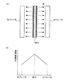
図3は、上述した発電停止後の運転制御処理による作用・効果を示す説明図である。上述した運転制御処理のステップS130において、所定期間、燃料電池スタック100による発電を行うことによって、図3(b)に示したように、膜電極接合体(MEA:Membrane Electrode Assembly)とセパレータとの間に、温度勾配、すなわち、蒸気圧勾配が形成される。すると、この蒸気圧勾配によって、膜電極接合体に含まれる生成水に、蒸気圧が高い膜電極接合体側から蒸気圧が低いセパレータ側へ移動する駆動力が作用するため、図3(a)に示したように、膜電極接合体に含まれる生成水は、膜電極接合体側からセパレータ側へ移動する。こうすることによって、膜電極接合体に含まれる生成水の量を減少させることができる。
A3. Action / effect:
FIG. 3 is an explanatory diagram showing the operation and effect of the operation control process after the power generation is stopped. In step S130 of the operation control process described above, power generation by the
以上説明した第1実施例の燃料電池システム1000によれば、上述した運転制御によって、膜電極接合体に含まれる生成水が凍結する直前に、この生成水を、膜電極接合体からセパレータ側に移動させることができるので、氷点下の低温環境下における膜電極接合体での生成水の凍結を抑制し、燃料電池システム1000の低温始動性を向上させることができる。また、上記運転制御において、燃料電池スタック100による発電(図2のステップS130)は、膜電極接合体とセパレータとの間に温度勾配が形成されるまでの期間のみ行われ、その後、速やかに停止されるので、先に説明した従来技術、すなわち、燃料電池の内部に残留した生成水を燃料電池の外部に排出させる運転や、燃料電池の温度を凍結温度よりも高い温度に維持する運転と比較して、燃料電池システム1000のエネルギ効率の低下を抑制することができる。
According to the
B.第2実施例:
第2実施例の燃料電池システムの構成は、第1実施例の燃料電池システム1000の構成と同じである。ただし、燃料電池スタック100による発電停止後の運転制御処理が、第1実施例と異なっている。以下、第2実施例の燃料電池システムにおいて、燃料電池スタック100による発電停止後の運転制御処理について説明する。
B. Second embodiment:
The configuration of the fuel cell system of the second embodiment is the same as the configuration of the
図4は、第2実施例における燃料電池スタック100による発電停止後の運転制御処理の流れを示すフローチャートである。この処理は、制御ユニット80のCPUが実行する処理である。
FIG. 4 is a flowchart showing a flow of operation control processing after power generation is stopped by the
まず、CPUは、温度センサ90によって、所定周期で燃料電池スタック100の温度を検出する(ステップS200)。これは、第1実施例の運転制御処理のステップS100と同様である。
First, the CPU detects the temperature of the
そして、CPUは、燃料電池スタック100の温度の変化率(低下率)を算出し、燃料電池スタック100の温度と、燃料電池スタック100の温度の変化率とに基づいて、燃料電池スタック100内の膜電極接合体における生成水の凍結を予測する(ステップS210)。そして、膜電極接合体において、生成水が凍結しないと判断された場合には(ステップS220:NO)、ステップS200に戻る。
Then, the CPU calculates the rate of change (decrease rate) of the temperature of the
一方、膜電極接合体において、生成水が凍結する判断された場合には(ステップS220:YES)、CPUは、膜電極接合体の温度が氷点下になる直前のタイミングで、冷却媒体を循環させるためのポンプ70、および、ラジエータ71を起動して、燃料電池スタック100に冷却媒体を循環させ(ステップS230)、所定期間、セパレータを冷却し、膜電極接合体とセパレータとの間に、温度勾配を形成する。なお、先に説明したように、燃料電池スタック100は、断熱性を有するケース内に収納されており、ポンプ70や、ラジエータ71等の冷却装置は、ケース外に配置されているため、冷却媒体の温度は、セパレータの温度よりも低い。このため、燃料電池スタック100に冷却媒体を循環させることによって、セパレータの温度を低下させることができる。この処理は、本発明における温度勾配形成制御に相当する。その後、CPUは、ポンプ70、および、ラジエータ71を停止して、冷却媒体の循環を停止し(ステップS240)、この処理を終了する。
On the other hand, when it is determined that the generated water is frozen in the membrane electrode assembly (step S220: YES), the CPU circulates the cooling medium at a timing immediately before the temperature of the membrane electrode assembly becomes below freezing point. The
以上説明した第2実施例の燃料電池システム1000によっても、第1実施例の燃料電池システム1000と同様に、膜電極接合体に含まれる生成水が凍結する直前に、膜電極接合体とセパレータとの間に温度勾配を形成し、この生成水を、膜電極接合体からセパレータ側に移動させることができるので、氷点下の低温環境下における膜電極接合体での生成水の凍結を抑制し、燃料電池システム1000の低温始動性を向上させることができる。また、上記運転制御において、冷却水の循環(図4のステップS230)は、膜電極接合体とセパレータとの間に温度勾配が形成されるまでの期間のみ行われ、その後、速やかに停止されるので、第1実施例と同様に、先に説明した従来技術、すなわち、燃料電池の内部に残留した生成水を燃料電池の外部に排出させる運転や、燃料電池の温度を凍結温度よりも高い温度に維持する運転と比較して、燃料電池システム1000のエネルギ効率の低下を抑制することができる。
In the
C.第3実施例:
C1.燃料電池システムの構成:
図5は、本発明の第3実施例としての燃料電池システム1000Aの概略構成を示す説明図である。この燃料電池システム1000Aの構成は、第1実施例、および、第2実施例の燃料電池システム1000の構成とほぼ同じである。ただし、第3実施例の燃料電池システム1000Aは、図示するように、配管53から配管61に水素を流すための配管58と、水素を燃料電池スタック100に流すか、配管58に流すかを切り換える三方弁59とを備えている。そして、コンプレッサ60を駆動させて空気を配管61に流すとともに、三方弁59を制御して、水素を配管61に流すことによって、燃料電池スタック100のカソードに、水素と空気との混合ガスを流すことができる。また、燃料電池システム1000Aは、制御ユニット80の代わりに、制御ユニット80Aを備えている。
C. Third embodiment:
C1. Configuration of fuel cell system:
FIG. 5 is an explanatory diagram showing a schematic configuration of a
C2.発電停止後の運転制御処理:
図6は、第3実施例における燃料電池スタック100による発電停止後の運転制御処理の流れを示すフローチャートである。この処理は、制御ユニット80AのCPUが実行する処理である。
C2. Operation control processing after stopping power generation:
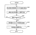
FIG. 6 is a flowchart showing a flow of operation control processing after power generation is stopped by the
まず、CPUは、温度センサ90によって、所定周期で燃料電池スタック100の温度を検出する(ステップS300)。これは、第1実施例の運転制御処理のステップS100と同様である。
First, the CPU detects the temperature of the
そして、CPUは、燃料電池スタック100の温度の変化率(低下率)を算出し、燃料電池スタック100の温度と、燃料電池スタック100の温度の変化率とに基づいて、燃料電池スタック100内の膜電極接合体における生成水の凍結を予測する(ステップS310)。そして、膜電極接合体において、生成水が凍結しないと判断された場合には(ステップS320:NO)、ステップS300に戻る。
Then, the CPU calculates the rate of change (decrease rate) of the temperature of the
一方、膜電極接合体において、生成水が凍結する判断された場合には(ステップS320:YES)、CPUは、膜電極接合体の温度が氷点下になる直前のタイミングで、シャットバルブ51、レギュレータ52を開弁し、また、配管53から配管58に水素が流れるように三方弁59を制御するとともに、コンプレッサ60を起動して、膜電極接合体のカソードに、所定期間、水素と空気との混合ガスを供給する(ステップS330)。すると、膜電極接合体のカソードの触媒層に含まれる触媒で、水素と空気に含まれる酸素とが燃焼し、この燃焼による膜電極接合体(触媒層)の発熱によって、膜電極接合体とセパレータとの間に、温度勾配が形成される。この処理は、本発明における温度勾配形成制御に相当する。その後、CPUは、シャットバルブ51、レギュレータ52を閉弁し、三方弁59の状態を元に戻すとともに、コンプレッサ60を停止して、膜電極接合体のカソードへの混合ガスの供給を停止し(ステップS340)、この処理を終了する。
On the other hand, when it is determined that the generated water is frozen in the membrane electrode assembly (step S320: YES), the CPU immediately shuts down the shut
以上説明した第3実施例の燃料電池システム1000Aによっても、第1実施例の1000と同様に、膜電極接合体に含まれる生成水が凍結する直前に、膜電極接合体とセパレータとの間に温度勾配を形成し、この生成水を、膜電極接合体からセパレータ側に移動させることができるので、氷点下の低温環境下における膜電極接合体での生成水の凍結を抑制し、燃料電池システム1000の低温始動性を向上させることができる。また、上記運転制御において、膜電極接合体のカソードへの混合ガスの供給(図6のステップS330)は、膜電極接合体とセパレータとの間に温度勾配が形成されるまでの期間のみ行われ、その後、速やかに停止されるので、第1実施例と同様に、先に説明した従来技術、すなわち、燃料電池の内部に残留した生成水を燃料電池の外部に排出させる運転や、燃料電池の温度を凍結温度よりも高い温度に維持する運転と比較して、燃料電池システム1000Aのエネルギ効率の低下を抑制することができる。
Also in the
D.変形例:
以上、本発明のいくつかの実施の形態について説明したが、本発明はこのような実施の形態になんら限定されるものではなく、その要旨を逸脱しない範囲内において種々なる態様での実施が可能である。例えば、以下のような変形が可能である。
D. Variations:
As mentioned above, although several embodiment of this invention was described, this invention is not limited to such embodiment at all, and implementation in a various aspect is possible within the range which does not deviate from the summary. It is. For example, the following modifications are possible.
D1.変形例1:
上述した第1ないし第3実施例の内容を組み合わせるようにしてもよい。例えば、第1実施例における燃料電池スタック100による発電停止後の運転制御処理と、第2実施例における燃料電池スタック100による発電停止後の運転制御処理とを組み合わせて、燃料電池スタック100の膜電極接合体において生成水が凍結すると予測されたときに、発電を行うとともに、冷却媒体を循環させるようにしてもよい。また、第3実施例の燃料電池システム1000Aにおいて、燃料電池スタック100による発電停止後の運転制御処理と、第2実施例における燃料電池スタック100による発電停止後の運転制御処理とを組み合わせて、燃料電池スタック100の膜電極接合体において生成水が凍結すると予測されたときに、膜電極接合体のカソードの触媒層に含まれる触媒で、混合ガスを燃焼させるとともに、冷却媒体を循環させるようにしてもよい。
D1. Modification 1:
You may make it combine the content of the 1st thru | or 3rd Example mentioned above. For example, the membrane electrode of the
D2.変形例2:
上記第3実施例では、燃料電池システム1000Aは、配管58と三方弁59とを備え、燃料電池スタック100による発電停止後の運転制御処理において、膜電極接合体のカソードに上記混合ガスを供給し、カソードの触媒層に含まれる触媒で水素と酸素とを燃焼させるものとしたが、本発明は、これに限られない。膜電極接合体のアノード、および、カソードの少なくとも一方に、上記混合ガスを供給し、触媒層に含まれる触媒で水素と酸素とを燃焼させるようにすればよい。
D2. Modification 2:
In the third embodiment, the
D3.変形例3:
上記実施例では、燃料電池スタック100による発電停止後の運転制御処理において、燃料電池スタック100の温度と、燃料電池スタック100の温度の変化率とに基づいて、燃料電池スタック100内の膜電極接合体における生成水の凍結を予測するものとしたが、本発明は、これに限られない。例えば、燃料電池スタック100の外部の環境温度、環境温度の変化率、冷却媒体の温度、冷却媒体の温度の変化率を検出、あるいは、算出し、これらの少なくとも1つに基づいて、燃料電池スタック100内の膜電極接合体における生成水の凍結を予測するものとしてもよい。
D3. Modification 3:
In the above embodiment, in the operation control process after power generation is stopped by the
1000,1000A...燃料電池システム
100...燃料電池スタック
10a,10b...エンドプレート
20a,20b...絶縁板
30a,30b...集電板
40...単セル
50...水素タンク
51...シャットバルブ
52...レギュレータ
53...配管
54...循環配管
55...ポンプ
56...排出配管
57...排気バルブ
58...配管
59...三方弁
60...コンプレッサ
61...配管
62...排出配管
70...ポンプ
71...ラジエータ
72...配管
80,80A...制御ユニット
90...温度センサ
1000, 1000A ...
Claims (5)
電解質膜の両面に、それぞれ、アノード、および、カソードを接合してなる膜電極接合体を、セパレータによって挟持した燃料電池と、
前記アノードに燃料ガスを供給する燃料ガス供給部と、
前記カソードに酸化剤ガスを供給する酸化剤ガス供給部と、
前記燃料電池を冷却するための冷却媒体を、前記セパレータ内に形成された冷却媒体流路に循環させる冷却媒体循環部と、
制御部と、を備え、
前記制御部は、
前記燃料電池による発電停止後に、発電中に前記燃料ガスと前記酸化剤ガスとの電気化学反応によって生成された生成水が、前記膜電極接合体において凍結すると予測された際に、前記燃料ガス供給部と、前記酸化剤ガス供給部と、前記冷却媒体循環部とのうちの少なくとも1つを起動して、前記膜電極接合体の温度が前記セパレータの温度よりも相対的に高くなるように、前記膜電極接合体と前記セパレータとの間に温度勾配を形成する温度勾配形成制御を行い、前記膜電極接合体と前記セパレータとの間に前記温度勾配が形成された後に、前記温度勾配形成制御を停止する、
燃料電池システム。 A fuel cell system,
A fuel cell in which a membrane electrode assembly formed by joining an anode and a cathode on both surfaces of an electrolyte membrane is sandwiched between separators;
A fuel gas supply unit for supplying fuel gas to the anode;
An oxidant gas supply unit for supplying an oxidant gas to the cathode;
A cooling medium circulation section for circulating a cooling medium for cooling the fuel cell to a cooling medium flow path formed in the separator;
A control unit,
The controller is
When it is predicted that the generated water generated by the electrochemical reaction between the fuel gas and the oxidant gas during power generation will be frozen in the membrane electrode assembly after power generation is stopped by the fuel cell. And at least one of the oxidant gas supply unit and the cooling medium circulation unit, so that the temperature of the membrane electrode assembly is relatively higher than the temperature of the separator, Temperature gradient formation control is performed to form a temperature gradient between the membrane electrode assembly and the separator, and the temperature gradient formation control is performed after the temperature gradient is formed between the membrane electrode assembly and the separator. To stop the
Fuel cell system.
前記制御部は、前記温度勾配形成制御として、前記燃料ガス供給部、および、前記酸化剤ガス供給部を起動して、前記燃料電池による発電を行うことによって、前記膜電極接合体の温度を、前記セパレータの温度よりも高くする、
燃料電池システム。 The fuel cell system according to claim 1, wherein
As the temperature gradient formation control, the control unit activates the fuel gas supply unit and the oxidant gas supply unit, and performs power generation by the fuel cell, thereby controlling the temperature of the membrane electrode assembly, Higher than the temperature of the separator,
Fuel cell system.
前記制御部は、前記温度勾配形成制御として、前記冷却媒体循環部を起動して、前記セパレータに前記冷却媒体を循環させることによって、前記セパレータの温度を、前記膜電極接合体の温度よりも低くする、
燃料電池システム。 The fuel cell system according to claim 1, wherein
As the temperature gradient formation control, the control unit activates the cooling medium circulation unit and causes the cooling medium to circulate through the separator, so that the temperature of the separator is lower than the temperature of the membrane electrode assembly. To
Fuel cell system.
前記アノード、および、カソードは、前記燃料ガスと前記酸化剤ガスとの反応を促進するための触媒を含んでおり、
前記燃料電池システムは、さらに、前記アノード、および、前記カソードの少なくとも一方に、前記燃料ガスと前記酸化剤ガスとの混合ガスを供給する混合ガス供給部を備え、
前記制御部は、前記温度勾配形成制御として、前記混合ガス供給部を起動して、前記触媒で前記混合ガスを燃焼させることによって、前記膜電極接合体の温度を、前記セパレータの温度よりも高くする、
燃料電池システム。 The fuel cell system according to claim 1, wherein
The anode and the cathode include a catalyst for promoting a reaction between the fuel gas and the oxidant gas,
The fuel cell system further includes a mixed gas supply unit that supplies a mixed gas of the fuel gas and the oxidant gas to at least one of the anode and the cathode,
As the temperature gradient formation control, the control unit starts the mixed gas supply unit and burns the mixed gas with the catalyst, whereby the temperature of the membrane electrode assembly is made higher than the temperature of the separator. To
Fuel cell system.
前記燃料電池システムは、
電解質膜の両面に、それぞれ、アノード、および、カソードを接合してなる膜電極接合体を、セパレータによって挟持した燃料電池と、
前記アノードに燃料ガスを供給する燃料ガス供給部と、
前記カソードに酸化剤ガスを供給する酸化剤ガス供給部と、
前記燃料電池を冷却するための冷却媒体を、前記セパレータ内に形成された冷却媒体流路に循環させる冷却媒体循環部と、を備えており、
前記制御方法は、
前記前記燃料電池による発電停止後に、発電中に前記燃料ガスと前記酸化剤ガスとの電気化学反応によって生成された生成水が、前記膜電極接合体において凍結するか否かを予測する凍結予測工程と、
前記凍結予測工程によって、前記生成水が、前記膜電極接合体において凍結すると予測された際に、前記燃料ガス供給部と、前記酸化剤ガス供給部と、前記冷却媒体循環部とのうちの少なくとも1つを起動して、前記膜電極接合体の温度が前記セパレータの温度よりも相対的に高くなるように、前記膜電極接合体と前記セパレータとの間に温度勾配を形成する温度勾配形成工程と、
前記温度勾配形成工程によって、前記膜電極接合体と前記セパレータとの間に前記温度勾配が形成された後に、前記温度勾配形成工程を停止する工程と、
を備える制御方法。 A control method for a fuel cell system, comprising:
The fuel cell system includes:
A fuel cell in which a membrane electrode assembly formed by joining an anode and a cathode on both surfaces of an electrolyte membrane is sandwiched between separators;
A fuel gas supply unit for supplying fuel gas to the anode;
An oxidant gas supply unit for supplying an oxidant gas to the cathode;
A cooling medium circulating section for circulating a cooling medium for cooling the fuel cell to a cooling medium flow path formed in the separator, and
The control method is:
Freezing prediction step of predicting whether or not the generated water generated by the electrochemical reaction between the fuel gas and the oxidant gas during power generation is frozen in the membrane electrode assembly after power generation is stopped by the fuel cell. When,
When it is predicted by the freezing prediction step that the generated water is frozen in the membrane electrode assembly, at least one of the fuel gas supply unit, the oxidant gas supply unit, and the cooling medium circulation unit. A temperature gradient forming step of starting one and forming a temperature gradient between the membrane electrode assembly and the separator so that the temperature of the membrane electrode assembly is relatively higher than the temperature of the separator; When,
Stopping the temperature gradient forming step after the temperature gradient is formed between the membrane electrode assembly and the separator by the temperature gradient forming step;
A control method comprising:
Priority Applications (6)
| Application Number | Priority Date | Filing Date | Title |
|---|---|---|---|
| JP2008037268A JP2009199751A (en) | 2008-02-19 | 2008-02-19 | Fuel cell system, and method of controlling the same |
| DE112009000366.4T DE112009000366B4 (en) | 2008-02-19 | 2009-02-10 | Fuel cell system and method for controlling a fuel cell system |
| KR1020107018260A KR20100102225A (en) | 2008-02-19 | 2009-02-10 | Fuel cell system and fuel cell system control method |
| US12/918,005 US20110008695A1 (en) | 2008-02-19 | 2009-02-10 | Fuel cell system and method of controlling a fuel cell system |
| CN200980105694.2A CN101946352B (en) | 2008-02-19 | 2009-02-10 | The control method of fuel cell system and fuel cell system |
| PCT/JP2009/000536 WO2009104368A1 (en) | 2008-02-19 | 2009-02-10 | Fuel cell system and fuel cell system control method |
Applications Claiming Priority (1)
| Application Number | Priority Date | Filing Date | Title |
|---|---|---|---|
| JP2008037268A JP2009199751A (en) | 2008-02-19 | 2008-02-19 | Fuel cell system, and method of controlling the same |
Related Child Applications (1)
| Application Number | Title | Priority Date | Filing Date |
|---|---|---|---|
| JP2010066620A Division JP5120404B2 (en) | 2010-03-23 | 2010-03-23 | Fuel cell system and control method of fuel cell system |
Publications (1)
| Publication Number | Publication Date |
|---|---|
| JP2009199751A true JP2009199751A (en) | 2009-09-03 |
Family
ID=40985257
Family Applications (1)
| Application Number | Title | Priority Date | Filing Date |
|---|---|---|---|
| JP2008037268A Pending JP2009199751A (en) | 2008-02-19 | 2008-02-19 | Fuel cell system, and method of controlling the same |
Country Status (6)
| Country | Link |
|---|---|
| US (1) | US20110008695A1 (en) |
| JP (1) | JP2009199751A (en) |
| KR (1) | KR20100102225A (en) |
| CN (1) | CN101946352B (en) |
| DE (1) | DE112009000366B4 (en) |
| WO (1) | WO2009104368A1 (en) |
Cited By (1)
| Publication number | Priority date | Publication date | Assignee | Title |
|---|---|---|---|---|
| JP2016208726A (en) * | 2015-04-24 | 2016-12-08 | トヨタ自動車株式会社 | Control method for fuel cell system |
Families Citing this family (5)
| Publication number | Priority date | Publication date | Assignee | Title |
|---|---|---|---|---|
| KR101240979B1 (en) * | 2010-11-17 | 2013-03-11 | 현대자동차주식회사 | Purge device and method for cold starting of fuel cell |
| KR101592391B1 (en) * | 2013-12-30 | 2016-02-05 | 현대자동차주식회사 | Hydrogen supply apparatus of fuel cell stack |
| DE102014224380A1 (en) * | 2014-11-28 | 2016-06-02 | Bayerische Motoren Werke Aktiengesellschaft | Method for the predictive operation of a motor vehicle with a fuel cell system |
| DE102015215821A1 (en) | 2015-08-19 | 2017-02-23 | Deutsches Zentrum für Luft- und Raumfahrt e.V. | A fuel cell device and method of operating a fuel cell device |
| US10714773B2 (en) * | 2017-11-28 | 2020-07-14 | Toyota Motor Engineering & Manufacturing North America, Inc. | Cooling system dT/dt based control |
Citations (10)
| Publication number | Priority date | Publication date | Assignee | Title |
|---|---|---|---|---|
| US6103410A (en) * | 1998-06-05 | 2000-08-15 | International Fuel Cells Corporation | Start up of frozen fuel cell |
| JP2001189164A (en) * | 1999-12-22 | 2001-07-10 | General Motors Corp <Gm> | Cold starting of pem fuel cell |
| JP2001231108A (en) * | 2000-02-14 | 2001-08-24 | Yamaha Motor Co Ltd | Charging device for motor-driven vehicle |
| JP2004327366A (en) * | 2003-04-28 | 2004-11-18 | Nissan Motor Co Ltd | Fuel cell stack and its fuel cell system |
| JP2004353992A (en) * | 2003-05-30 | 2004-12-16 | Osaka Industrial Promotion Organization | Drier and drying method |
| JP2005108832A (en) * | 2003-09-12 | 2005-04-21 | Toyota Motor Corp | Fuel cell mounting apparatus and its system |
| JP2005310510A (en) * | 2004-04-21 | 2005-11-04 | Nippon Soken Inc | Fuel cell |
| JP2006107901A (en) * | 2004-10-05 | 2006-04-20 | Toyota Motor Corp | Fuel cell system |
| JP2007035392A (en) * | 2005-07-26 | 2007-02-08 | Nippon Soken Inc | Fuel cell system |
| JP2007305334A (en) * | 2006-05-09 | 2007-11-22 | Toyota Motor Corp | Fuel cell system |
Family Cites Families (5)
| Publication number | Priority date | Publication date | Assignee | Title |
|---|---|---|---|---|
| US7223490B2 (en) * | 2001-04-06 | 2007-05-29 | Honda Giken Kogyo Kabushiki Kaisha | Fuel cell employing local power generation when starting at low temperature |
| JP3835357B2 (en) | 2002-06-12 | 2006-10-18 | 株式会社デンソー | Fuel cell system |
| JP4461701B2 (en) | 2003-04-22 | 2010-05-12 | トヨタ自動車株式会社 | Mobile body equipped with a fuel cell |
| JP2005322527A (en) | 2004-05-10 | 2005-11-17 | Nissan Motor Co Ltd | Fuel cell system |
| JP4831417B2 (en) * | 2006-12-12 | 2011-12-07 | トヨタ自動車株式会社 | Fuel cell system |
-
2008
- 2008-02-19 JP JP2008037268A patent/JP2009199751A/en active Pending
-
2009
- 2009-02-10 DE DE112009000366.4T patent/DE112009000366B4/en not_active Expired - Fee Related
- 2009-02-10 WO PCT/JP2009/000536 patent/WO2009104368A1/en active Application Filing
- 2009-02-10 CN CN200980105694.2A patent/CN101946352B/en not_active Expired - Fee Related
- 2009-02-10 US US12/918,005 patent/US20110008695A1/en not_active Abandoned
- 2009-02-10 KR KR1020107018260A patent/KR20100102225A/en active Search and Examination
Patent Citations (10)
| Publication number | Priority date | Publication date | Assignee | Title |
|---|---|---|---|---|
| US6103410A (en) * | 1998-06-05 | 2000-08-15 | International Fuel Cells Corporation | Start up of frozen fuel cell |
| JP2001189164A (en) * | 1999-12-22 | 2001-07-10 | General Motors Corp <Gm> | Cold starting of pem fuel cell |
| JP2001231108A (en) * | 2000-02-14 | 2001-08-24 | Yamaha Motor Co Ltd | Charging device for motor-driven vehicle |
| JP2004327366A (en) * | 2003-04-28 | 2004-11-18 | Nissan Motor Co Ltd | Fuel cell stack and its fuel cell system |
| JP2004353992A (en) * | 2003-05-30 | 2004-12-16 | Osaka Industrial Promotion Organization | Drier and drying method |
| JP2005108832A (en) * | 2003-09-12 | 2005-04-21 | Toyota Motor Corp | Fuel cell mounting apparatus and its system |
| JP2005310510A (en) * | 2004-04-21 | 2005-11-04 | Nippon Soken Inc | Fuel cell |
| JP2006107901A (en) * | 2004-10-05 | 2006-04-20 | Toyota Motor Corp | Fuel cell system |
| JP2007035392A (en) * | 2005-07-26 | 2007-02-08 | Nippon Soken Inc | Fuel cell system |
| JP2007305334A (en) * | 2006-05-09 | 2007-11-22 | Toyota Motor Corp | Fuel cell system |
Cited By (1)
| Publication number | Priority date | Publication date | Assignee | Title |
|---|---|---|---|---|
| JP2016208726A (en) * | 2015-04-24 | 2016-12-08 | トヨタ自動車株式会社 | Control method for fuel cell system |
Also Published As
| Publication number | Publication date |
|---|---|
| DE112009000366B4 (en) | 2015-02-26 |
| CN101946352B (en) | 2015-09-16 |
| US20110008695A1 (en) | 2011-01-13 |
| KR20100102225A (en) | 2010-09-20 |
| DE112009000366T5 (en) | 2011-01-05 |
| WO2009104368A1 (en) | 2009-08-27 |
| CN101946352A (en) | 2011-01-12 |
Similar Documents
| Publication | Publication Date | Title |
|---|---|---|
| Amamou et al. | A comprehensive review of solutions and strategies for cold start of automotive proton exchange membrane fuel cells | |
| JP3999498B2 (en) | Fuel cell system and method for stopping the same | |
| JP5003073B2 (en) | Fuel cell system | |
| US20050227126A1 (en) | Method and apparatus for cold-starting a PEM fuel cell (PEMFC), and PEM fuel cell system | |
| JP2007035509A (en) | Fuel cell system | |
| US7678477B2 (en) | Method of operating a fuel cell stack | |
| WO2009104368A1 (en) | Fuel cell system and fuel cell system control method | |
| US20050053809A1 (en) | Method of starting up operation of fuel cell at low temperature | |
| JP2005044795A (en) | Low-temperature starting method for fuel cell | |
| EP2584637B1 (en) | Fuel cell | |
| JP2007227162A (en) | Fuel cell system | |
| CA2889414A1 (en) | Fuel cell system and control method thereof | |
| JP2006190616A (en) | Scavenging processor for fuel cell system, and method for scavenging | |
| JP2020017452A (en) | Fuel cell system and control method for fuel cell system | |
| JP5287368B2 (en) | Fuel cell system | |
| JP5120404B2 (en) | Fuel cell system and control method of fuel cell system | |
| JP7035982B2 (en) | Fuel cell system | |
| JP2006156181A (en) | Low-temperature starting method of fuel cell, and fuel cell system | |
| JP3661643B2 (en) | Fuel cell system | |
| JP2010086933A (en) | Fuel cell system | |
| JP2008135331A (en) | Fuel cell system, and control method of fuel cell system | |
| JP2013218923A (en) | Fuel cell system and fuel cell system activation method | |
| JP7435506B2 (en) | fuel cell system | |
| JP7367611B2 (en) | fuel cell system | |
| JP7380609B2 (en) | fuel cell system |
Legal Events
| Date | Code | Title | Description |
|---|---|---|---|
| A131 | Notification of reasons for refusal |
Free format text: JAPANESE INTERMEDIATE CODE: A131 Effective date: 20090526 |
|
| A521 | Written amendment |
Free format text: JAPANESE INTERMEDIATE CODE: A523 Effective date: 20090727 |
|
| A131 | Notification of reasons for refusal |
Free format text: JAPANESE INTERMEDIATE CODE: A131 Effective date: 20100119 |
|
| A02 | Decision of refusal |
Free format text: JAPANESE INTERMEDIATE CODE: A02 Effective date: 20100601 |