JP2008135331A - Fuel cell system, and control method of fuel cell system - Google Patents
Fuel cell system, and control method of fuel cell system Download PDFInfo
- Publication number
- JP2008135331A JP2008135331A JP2006321743A JP2006321743A JP2008135331A JP 2008135331 A JP2008135331 A JP 2008135331A JP 2006321743 A JP2006321743 A JP 2006321743A JP 2006321743 A JP2006321743 A JP 2006321743A JP 2008135331 A JP2008135331 A JP 2008135331A
- Authority
- JP
- Japan
- Prior art keywords
- fuel cell
- cell stack
- fastening load
- pressure
- cell system
- Prior art date
- Legal status (The legal status is an assumption and is not a legal conclusion. Google has not performed a legal analysis and makes no representation as to the accuracy of the status listed.)
- Pending
Links
Images


Classifications
-
- Y—GENERAL TAGGING OF NEW TECHNOLOGICAL DEVELOPMENTS; GENERAL TAGGING OF CROSS-SECTIONAL TECHNOLOGIES SPANNING OVER SEVERAL SECTIONS OF THE IPC; TECHNICAL SUBJECTS COVERED BY FORMER USPC CROSS-REFERENCE ART COLLECTIONS [XRACs] AND DIGESTS
- Y02—TECHNOLOGIES OR APPLICATIONS FOR MITIGATION OR ADAPTATION AGAINST CLIMATE CHANGE
- Y02E—REDUCTION OF GREENHOUSE GAS [GHG] EMISSIONS, RELATED TO ENERGY GENERATION, TRANSMISSION OR DISTRIBUTION
- Y02E60/00—Enabling technologies; Technologies with a potential or indirect contribution to GHG emissions mitigation
- Y02E60/30—Hydrogen technology
- Y02E60/50—Fuel cells
Abstract
Description
本発明は、燃料電池システム、および、燃料電池システムの制御方法に関するものである。 The present invention relates to a fuel cell system and a control method for the fuel cell system.
燃料ガス(例えば、水素)と酸化剤ガス(例えば、酸素)との電気化学反応によって発電する燃料電池がエネルギ源として注目されている。この燃料電池には、燃料ガスと酸化剤ガスとの電気化学反応によって発電するセルを、複数積層させたスタック構造を有するものがある(以下、燃料電池スタックと呼ぶ)。このような燃料電池スタックでは、一般に、複数のセルは、各セル内、および、各セル間の接触抵抗を低減したり、燃料電池スタック内に流れる流体(燃料ガス、酸化剤ガス、冷却水)の漏洩を防止したりするために、燃料電池スタックの外部からセルの積層方向に締結荷重が加えられ、締結部材によって締結される。 A fuel cell that generates electricity by an electrochemical reaction between a fuel gas (for example, hydrogen) and an oxidant gas (for example, oxygen) has attracted attention as an energy source. Some of the fuel cells have a stack structure in which a plurality of cells that generate power by an electrochemical reaction between a fuel gas and an oxidant gas are stacked (hereinafter referred to as a fuel cell stack). In such a fuel cell stack, generally, a plurality of cells reduce the contact resistance in each cell and between each cell, or fluids flowing in the fuel cell stack (fuel gas, oxidant gas, cooling water) In order to prevent leakage, a fastening load is applied in the cell stacking direction from the outside of the fuel cell stack, and is fastened by a fastening member.
そして、このような燃料電池スタックにおける複数のセルの締結方法に関し、従来、種々の技術が提案されている(例えば、下記特許文献1参照)。例えば、下記特許文献1には、燃料電池スタックを構成するセパレータの内部に面圧発生板を設け、この面圧発生板によって形成された空間に、流体冷媒を流入させたり、反応ガスを流入させたり、高圧流体を流入させたりすることによって、燃料電池スタックの内部から上記締結荷重を得る技術が記載されている。 Various techniques have been proposed for fastening a plurality of cells in such a fuel cell stack (see, for example, Patent Document 1 below). For example, in Patent Document 1 below, a surface pressure generating plate is provided inside a separator constituting the fuel cell stack, and fluid refrigerant or reaction gas is allowed to flow into a space formed by the surface pressure generating plate. Or a technique for obtaining the fastening load from the inside of the fuel cell stack by flowing a high-pressure fluid.
しかし、上記特許文献1に記載された技術では、各セパレータの内部に面圧発生板を備えるため、セパレータの構成の複雑化、ひいては燃料電池スタックの構成の複雑化を招いていた。さらに、上記特許文献1に記載された技術では、燃料電池スタックに上記締結圧力を加えるための具体的な制御方法や、燃料電池スタックを構成する部材の熱膨張や、クリープ等による締結荷重の経時的な変化については、考慮されていなかった。 However, since the technique described in Patent Document 1 includes a surface pressure generating plate inside each separator, the configuration of the separator is complicated, and thus the configuration of the fuel cell stack is complicated. Furthermore, in the technique described in Patent Document 1, a specific control method for applying the fastening pressure to the fuel cell stack, the thermal expansion of the members constituting the fuel cell stack, the aging of the fastening load due to creep, etc. This change was not taken into account.
本発明は、上述の課題を解決するためになされたものであり、燃料電池システムにおいて、比較的簡易な構成で、燃料電池スタックに加わる締結荷重を調整することを目的とする。 The present invention has been made to solve the above-described problems, and an object of the present invention is to adjust the fastening load applied to the fuel cell stack with a relatively simple configuration in the fuel cell system.
上述の課題の少なくとも一部を解決するため、本発明では、以下の構成を採用した。本発明の第1の燃料電池システムは、燃料ガスと酸化剤ガスとの電気化学反応によって発電するセルを複数積層させるとともに、前記セルの積層方向に所定の締結荷重が加えられた燃料電池スタックと、前記締結荷重を検出する締結荷重検出部と、前記検出された締結荷重に基づいて、前記燃料電池スタック内における前記燃料ガス、および、前記酸化剤ガスのうちの少なくとも一方の圧力を制御する圧力制御部と、を備えることを要旨とする。 In order to solve at least a part of the above-described problems, the present invention employs the following configuration. A first fuel cell system according to the present invention includes a fuel cell stack in which a plurality of cells that generate power by an electrochemical reaction between a fuel gas and an oxidant gas are stacked, and a predetermined fastening load is applied in the stacking direction of the cells. A pressure for controlling the pressure of at least one of the fuel gas and the oxidant gas in the fuel cell stack based on the detected fastening load, and a fastening load detector for detecting the fastening load. And a control unit.
本発明において、圧力制御部は、例えば、燃料電池スタックに供給される燃料ガスの供給圧力、酸化剤ガスの供給圧力、燃料電池スタックから排出される未消費の燃料ガスであるアノードオフガスの背圧、燃料電池スタックから排出される未消費の酸化剤ガスであるカソードオフガスの背圧のうちの少なくとも一部を制御することによって、燃料電池スタック内における燃料ガス、および、酸化剤ガスのうちの少なくとも一方の圧力を制御する。こうすることによって、燃料電池システムにおいて、比較的簡易な構成で、燃料電池スタック内の圧力を調整し、燃料電池スタックに加わる締結荷重を調整することができる。 In the present invention, the pressure control unit, for example, the supply pressure of the fuel gas supplied to the fuel cell stack, the supply pressure of the oxidant gas, and the back pressure of the anode off gas that is unconsumed fuel gas discharged from the fuel cell stack , By controlling at least part of the back pressure of the cathode offgas that is unconsumed oxidant gas discharged from the fuel cell stack, and at least part of the fuel gas in the fuel cell stack and the oxidant gas One pressure is controlled. By doing so, the pressure in the fuel cell stack can be adjusted and the fastening load applied to the fuel cell stack can be adjusted with a relatively simple configuration in the fuel cell system.
上記燃料電池システムにおいて、前記圧力制御部は、前記検出された締結荷重が所定値以下であるときに、前記燃料電池スタック内における前記燃料ガス、および、前記酸化剤ガスのうちの少なくとも一方の圧力を増加させるようにしてもよい。こうすることによって、燃料電池スタックを構成する部材のクリープ等によって、上記締結荷重が経時的に低下した場合に、燃料電池スタック内の圧力を増加させ、上記締結荷重を増加させることができる。したがって、燃料電池スタックに加わる締結荷重の経時的な低下に伴う電池性能の低下を抑制することができる。 In the fuel cell system, when the detected fastening load is equal to or less than a predetermined value, the pressure control unit is configured to pressure at least one of the fuel gas and the oxidant gas in the fuel cell stack. May be increased. By doing so, when the fastening load decreases with time due to creep of the members constituting the fuel cell stack, the pressure in the fuel cell stack can be increased and the fastening load can be increased. Therefore, it is possible to suppress a decrease in cell performance accompanying a decrease in fastening load applied to the fuel cell stack over time.
なお、上記燃料電池システムにおいて、前記圧力制御部は、前記検出された締結荷重が所定値以下であるときに、前記燃料電池スタック内における前記燃料ガス、および、前記酸化剤ガスの双方の圧力を増加させるようにすることが好ましい。 In the fuel cell system, when the detected fastening load is equal to or less than a predetermined value, the pressure control unit sets the pressures of both the fuel gas and the oxidant gas in the fuel cell stack. It is preferable to increase it.
燃料電池スタックを構成する複数のセルは、それぞれ膜電極接合体を備える。そして、燃料電池スタック内において、燃料ガスの圧力、および、酸化剤ガスの圧力のいずれか一方のみを増加させた場合、膜電極接合体の一方の面に過剰な圧力が加わり、膜電極接合体が破損するおそれがある。本発明では、燃料電池スタック内における燃料ガス、および、酸化剤ガスの双方の圧力を増加させるので、膜電極接合体の両面における圧力差を小さくし、膜電極接合体の破損を抑制することができる。 Each of the plurality of cells constituting the fuel cell stack includes a membrane electrode assembly. In the fuel cell stack, when only one of the pressure of the fuel gas and the pressure of the oxidant gas is increased, excessive pressure is applied to one surface of the membrane electrode assembly, and the membrane electrode assembly May be damaged. In the present invention, since the pressures of both the fuel gas and the oxidant gas in the fuel cell stack are increased, it is possible to reduce the pressure difference between both surfaces of the membrane electrode assembly and to prevent the membrane electrode assembly from being damaged. it can.
本発明の第2の燃料電池システムは、燃料ガスと酸化剤ガスとの電気化学反応によって発電するセルを複数積層させるとともに、前記セルの積層方向に所定の締結荷重が加えられた燃料電池スタックと、前記燃料電池スタックに冷却媒体を流すことによって、前記燃料電池スタックを冷却する冷却システムと、前記締結荷重を検出する締結荷重検出部と、前記検出された締結荷重に基づいて、前記燃料電池スタック内における前記冷却媒体の圧力を制御する冷却媒体圧力制御部と、を備えることを要旨とする。 A second fuel cell system according to the present invention includes a fuel cell stack in which a plurality of cells that generate power by an electrochemical reaction between a fuel gas and an oxidant gas are stacked, and a predetermined fastening load is applied in the stacking direction of the cells. A cooling system that cools the fuel cell stack by flowing a cooling medium through the fuel cell stack, a fastening load detection unit that detects the fastening load, and the fuel cell stack based on the detected fastening load. And a cooling medium pressure control unit that controls the pressure of the cooling medium inside.
本発明において、冷却システムは、冷却媒体を冷却するためのラジエータや、冷却媒体を、燃料電池スタックとラジエータとの間で循環させるための循環ポンプ等を備えている。そして、冷却媒体圧力制御部は、例えば、上記冷却システムが備える循環ポンプの出力を制御し、燃料電池スタックに供給される冷却媒体の流量を調整することによって、燃料電池スタック内における冷却媒体の圧力を制御する。こうすることによって、燃料電池システムにおいて、比較的簡易な構成で、燃料電池スタック内の圧力を調整し、燃料電池スタックに加わる締結荷重を調整することができる。 In the present invention, the cooling system includes a radiator for cooling the cooling medium, a circulation pump for circulating the cooling medium between the fuel cell stack and the radiator, and the like. Then, the cooling medium pressure control unit controls the output of the circulation pump included in the cooling system, for example, and adjusts the flow rate of the cooling medium supplied to the fuel cell stack to thereby adjust the pressure of the cooling medium in the fuel cell stack. To control. By doing so, the pressure in the fuel cell stack can be adjusted and the fastening load applied to the fuel cell stack can be adjusted with a relatively simple configuration in the fuel cell system.
上記燃料電池システムにおいて、前記冷却媒体圧力制御部は、前記検出された締結荷重が所定値以下であるときに、前記燃料電池スタック内における前記冷却媒体の圧力を増加させるようにしてもよい。こうすることによって、燃料電池スタックを構成する部材のクリープ等によって、上記締結荷重が経時的に低下した場合に、燃料電池スタック内の圧力を増加させ、上記締結荷重を増加させることができる。したがって、燃料電池スタックに加わる締結荷重の経時的な低下に伴う電池性能の低下を抑制することができる。 In the fuel cell system, the cooling medium pressure control unit may increase the pressure of the cooling medium in the fuel cell stack when the detected fastening load is a predetermined value or less. By doing so, when the fastening load decreases with time due to creep of the members constituting the fuel cell stack, the pressure in the fuel cell stack can be increased and the fastening load can be increased. Therefore, it is possible to suppress a decrease in cell performance accompanying a decrease in fastening load applied to the fuel cell stack over time.
本発明の第3の燃料電池システムは、燃料ガスと酸化剤ガスとの電気化学反応によって発電するセルを複数積層させるとともに、前記セルの積層方向に所定の締結荷重が加えられた燃料電池スタックと、前記燃料電池スタックに冷却媒体を流すことによって、前記燃料電池スタックを冷却する冷却システムと、前記締結荷重を検出する締結荷重検出部と、前記検出された締結荷重に基づいて、前記燃料電池スタックに流す前記冷却媒体の温度を制御する冷却媒体温度制御部と、を備えることを要旨とする。 A third fuel cell system according to the present invention includes a fuel cell stack in which a plurality of cells that generate power by an electrochemical reaction between a fuel gas and an oxidant gas are stacked, and a predetermined fastening load is applied in the stacking direction of the cells. A cooling system that cools the fuel cell stack by flowing a cooling medium through the fuel cell stack, a fastening load detection unit that detects the fastening load, and the fuel cell stack based on the detected fastening load. And a cooling medium temperature control unit that controls the temperature of the cooling medium that flows through the apparatus.
本発明において、冷却システムは、冷却媒体を冷却するためのラジエータや、冷却媒体を、燃料電池スタックとラジエータとの間で循環させるための循環ポンプ等を備えている。そして、冷却媒体温度制御部は、例えば、上記冷却システムが備える循環ポンプの出力を制御したり、冷却媒体の冷却能力を制御したりすることによって、燃料電池スタック内における冷却媒体の温度を制御する。そして、冷却媒体の温度変化に応じて、冷却媒体の体積や、燃料電池スタックを構成する部材の体積が変動する。こうすることによって、燃料電池システムにおいて、比較的簡易な構成で、燃料電池スタックに加わる締結荷重を調整することができる。 In the present invention, the cooling system includes a radiator for cooling the cooling medium, a circulation pump for circulating the cooling medium between the fuel cell stack and the radiator, and the like. The cooling medium temperature control unit controls the temperature of the cooling medium in the fuel cell stack, for example, by controlling the output of the circulation pump provided in the cooling system or by controlling the cooling capacity of the cooling medium. . And according to the temperature change of a cooling medium, the volume of a cooling medium and the volume of the member which comprises a fuel cell stack are fluctuate | varied. By doing so, the fastening load applied to the fuel cell stack can be adjusted with a relatively simple configuration in the fuel cell system.
上記燃料電池システムにおいて、前記冷却媒体温度制御部は、前記検出された締結荷重が所定値以下であるときに、前記燃料電池スタック内における前記冷却媒体の温度を上昇させるようにしてもよい。こうすることによって、冷却媒体や、燃料電池スタックを構成する部材が熱膨張するため、燃料電池スタックを構成する部材のクリープ等によって、上記締結荷重が経時的に低下した場合に、上記締結荷重を増加させることができる。したがって、燃料電池スタックに加わる締結荷重の経時的な低下に伴う電池性能の低下を抑制することができる。 In the fuel cell system, the cooling medium temperature control unit may increase the temperature of the cooling medium in the fuel cell stack when the detected fastening load is a predetermined value or less. By doing so, the cooling medium and the members constituting the fuel cell stack are thermally expanded. Therefore, when the fastening load is reduced over time due to creep of the members constituting the fuel cell stack, the fastening load is reduced. Can be increased. Therefore, it is possible to suppress a decrease in cell performance accompanying a decrease in fastening load applied to the fuel cell stack over time.
本発明は、適宜、組み合わせて構成することもできる。また、本発明は、上述の燃料電池システムとしての構成の他、燃料電池システムの制御方法の発明として構成することもできる。また、これらを実現するコンピュータプログラム、およびそのプログラムを記録した記録媒体、そのプログラムを含み搬送波内に具現化されたデータ信号など種々の態様で実現することが可能である。なお、それぞれの態様において、先に示した種々の付加的要素を適用することが可能である。 The present invention can be configured in combination as appropriate. Further, the present invention can be configured as an invention of a control method for a fuel cell system in addition to the above-described configuration as a fuel cell system. Further, the present invention can be realized in various modes such as a computer program that realizes these, a recording medium that records the program, and a data signal that includes the program and is embodied in a carrier wave. In addition, in each aspect, it is possible to apply the various additional elements shown above.
本発明をコンピュータプログラムまたはそのプログラムを記録した記録媒体等として構成する場合には、燃料電池システムの動作を制御するプログラム全体として構成するものとしてもよいし、本発明の機能を果たす部分のみを構成するものとしてもよい。また、記録媒体としては、フレキシブルディスクやCD−ROM、DVD−ROM、光磁気ディスク、ICカード、ROMカートリッジ、パンチカード、バーコードなどの符号が印刷された印刷物、コンピュータの内部記憶装置(RAMやROMなどのメモリ)および外部記憶装置などコンピュータが読み取り可能な種々の媒体を利用できる。 When the present invention is configured as a computer program or a recording medium storing the program, the entire program for controlling the operation of the fuel cell system may be configured, or only the portion that performs the function of the present invention is configured. It is good also as what to do. The recording medium includes a flexible disk, a CD-ROM, a DVD-ROM, a magneto-optical disk, an IC card, a ROM cartridge, a punch card, a printed matter on which a code such as a barcode is printed, a computer internal storage device (RAM or Various types of computer-readable media such as a memory such as a ROM and an external storage device can be used.
以下、本発明の実施の形態について、実施例に基づき説明する。
A.第1実施例:
A1.燃料電池システムの構成:
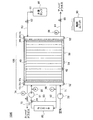
図1は、本発明の一実施例としての燃料電池システム1000の概略構成を示す説明図である。この燃料電池システム1000は、電気自動車に車載されているものとする。燃料電池スタック100は、燃料ガス(水素)と酸化剤ガス(酸素)との電気化学反応によって発電するセル40を、複数積層させたスタック構造を有している。各セル40は、プロトン伝導性を有する電解質膜の両面に、それぞれアノード、および、カソードを接合した膜電極接合体を備えている。本実施例では、電解質膜として、ナフィオン(登録商標)等の固体高分子膜を用いるものとした。電解質として、固体酸化物等、他の電解質を用いるものとしてもよい。なお、セル40の積層数は、燃料電池スタック100に要求される出力に応じて任意に設定可能である。
Hereinafter, embodiments of the present invention will be described based on examples.
A. First embodiment:
A1. Configuration of fuel cell system:
FIG. 1 is an explanatory diagram showing a schematic configuration of a
燃料電池スタック100は、一端から、エンドプレート10a、絶縁板20a、集電板30a、複数のセル40、集電板30b、絶縁板20b、エンドプレート10bの順に積層することによって構成されている。これらには、燃料電池スタック100内に、水素や、空気や、冷却水を流すための供給口や、排出口が設けられている。また、燃料電池スタック100内部には、水素や、空気や、冷却水を、それぞれ各セル40に分配して供給するための供給マニホールド(水素供給マニホールド、空気供給マニホールド、冷却水供給マニホールド)や、各セル40のアノードおよびカソードからそれぞれ排出されるアノードオフガスおよびカソードオフガスや、冷却水を集合させて燃料電池スタック100の外部に排出するための排出マニホールド(アノードオフガス排出マニホールド、カソードオフガス排出マニホールド、冷却水排出マニホールド)が形成されている。
The
エンドプレート10a,10bは、剛性を確保するため、鋼等の金属によって形成されている。絶縁板20a,20bは、ゴムや、樹脂等の絶縁性部材によって形成されている。集電板30a,30bは、緻密質カーボンや、銅板などのガス不透過な導電性部材によって形成されている。集電板30a,30bには、それぞれ図示しない出力端子が設けられており、燃料電池スタック100で発電した電力を出力可能となっている。
The
燃料電池スタック100には、スタック構造のいずれかの箇所における接触抵抗の増加等による電池性能の低下を抑制したり、ガスの漏洩を抑制したりするために、スタック構造の積層方向に、外部から所定の押圧力(締結荷重)が加えられる。そして、この締結荷重が加えられた状態で、テンションプレート50の両端を、ボルト52によって、エンドプレート10a,10bにそれぞれ固定することによって、締結荷重が維持されている。
In the
テンションプレート50には、テンションプレート50の歪み量を検出する歪みセンサ54が設置されている。そして、歪みセンサ54によって検出されたテンションプレート50の歪み量に基づいて、後述する制御ユニット90は、燃料電池スタック100に加わっている締結荷重を算出し、後述する運転制御処理を実行する。歪みセンサ54は、本発明における締結荷重検出部に相当する。また、燃料電池スタック100には、燃料電池スタック100の温度を検出する温度センサ42が設置されている。
The
燃料電池スタック100のアノードには、配管63を介して、高圧水素を貯蔵した水素タンク60から、燃料ガスとしての水素が供給される。水素タンク60の代わりに、アルコール、炭化水素、アルデヒドなどを原料とする改質反応によって水素リッチなガスを生成し、アノードに供給するものとしてもよい。
Hydrogen as fuel gas is supplied to the anode of the
水素タンク60に貯蔵された高圧水素は、水素タンク60の出口に設けられたシャットバルブ61や、レギュレータ62によって、圧力、および、供給量が調整されて、水素供給マニホールドを介して、各セル40のアノードに供給される。各セル40から排出されるアノードオフガスは、アノードオフガス排出マニホールドに接続された排出配管64を介して、燃料電池スタック100の外部に排出される。
The pressure and supply amount of the high-pressure hydrogen stored in the hydrogen tank 60 are adjusted by a
なお、排出配管64には、レギュレータ65、および、圧力センサ66が配設されており、レギュレータ65を調整することによって、アノードオフガスの背圧を調整することができる。レギュレータ62、および、レギュレータ65は、本発明における圧力制御部に相当する。
In addition, the
燃料電池スタック100のカソードには、配管71を介して、エアコンプレッサ70によって圧縮された圧縮空気が、酸素を含有した酸化剤ガスとして供給される。そして、この圧縮空気は、配管71に接続された空気供給マニホールドを介して、各セル40のカソードに供給される。各セル40のカソードから排出されるカソードオフガスは、カソードオフガス排出マニホールドに接続された排出配管72を介して、燃料電池スタック100の外部に排出される。
The compressed air compressed by the
なお、排出配管72には、レギュレータ73、および、圧力センサ74が配設されており、レギュレータ73を調整することによって、アノードオフガスの背圧を調整することができる。また、エアコンプレッサ70、および、レギュレータ73は、本発明における圧力制御部に相当する。
In addition, the
燃料電池スタック100は、上述した電気化学反応によって発熱するため、燃料電池スタック100には、燃料電池スタック100を冷却するための冷却水も供給される。この冷却水は、循環ポンプ81によって、冷却水用の配管82を流れ、ラジエータ80によって冷却されて、燃料電池スタック100に供給される。また、配管82には、図示するように、ラジエータ80を通さずに、冷却水を循環させるためのバイパス配管83が接続されており、さらに、配管82とバイパス配管83との一方の接続部には、三方弁84が配設されている。したがって、三方弁84を切り換えることによって、ラジエータ80を通さずに、配管82、および、バイパス配管83を介して、冷却水を循環させることも可能である。そして、ラジエータ80を通さずに冷却水の循環を行った場合には、冷却水の温度は上昇する。
Since the
なお、配管82には、冷却水の供給圧力を検出する圧力センサ85や、燃料電池スタック100から排出された冷却水の温度を検出する温度センサ86が配設されている。循環ポンプ81は、本発明における冷却媒体圧力制御部に相当する。また、循環ポンプ81、および、三方弁84は、本発明における冷却媒体温度制御部に相当する。
The
燃料電池システム1000の運転は、制御ユニット90によって制御される。制御ユニット90は、内部にCPU、RAM、ROMなどを備えるマイクロコンピュータとして構成されており、各種センサの出力に基づいて、ROMに記憶されたプログラムに従って、例えば、各種バルブや、ポンプの駆動等、燃料電池システム1000の全体の運転を制御する。制御ユニット90は、本発明における圧力制御部、冷却媒体圧力制御部、冷却媒体温度制御部に相当する。
The operation of the
A2.運転制御:
先に説明したように、燃料電池スタック100は、外部からの締結荷重が加えられた状態で、テンションプレート50や、ボルト52によって締結されている。そして、燃料電池スタック100の製造初期に設定された締結荷重は、長期間に亘って維持することは困難であり、経時的に変化する。すなわち、上述した締結荷重は、燃料電池スタック100を構成する部材の熱膨張によって増加したり、燃料電池スタック100を構成する部材のクリープ等によって低下したりする。そして、上述した締結荷重が過剰に増加した場合には、燃料電池スタック100を構成する部材の早期劣化を招く。また、上述した締結荷重が過剰に低下した場合には、接触抵抗の低下を招き、燃料電池スタック100の電池性能の低下を招く。このため、本実施例の燃料電池システム1000では、以下に説明する運転制御処理を実行することによって、燃料電池スタック100に加わる締結荷重を調整する。
A2. Operation control:
As described above, the
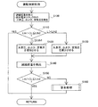
図2は、第1実施例の運転制御処理の流れを示すフローチャートである。この処理は、燃料電池スタック100による発電中に、制御ユニット90のCPUが実行する処理である。
FIG. 2 is a flowchart showing a flow of operation control processing of the first embodiment. This process is a process executed by the CPU of the
まず、CPUは、歪みセンサ54によって、燃料電池スタック100に加わっている締結荷重Lを検出する。また、圧力センサ66、および、圧力センサ74によって、燃料電池スタック100内における水素の圧力(水素圧)、および、空気の圧力(空気圧)を検出する(ステップS100)。
First, the CPU detects the fastening load L applied to the
次に、CPUは、歪みセンサ54によって検出された締結荷重Lが、所定範囲内にあるか否かを判断する(ステップS110)。本実施例では、所定範囲の上限値、および、下限値として、下限値Lth1、および、上限値Lth2が予め設定されているものとした。これらの値は、例えば、燃料電池スタック100を構成する部材の材質等に応じて、任意に設定可能である。
Next, the CPU determines whether or not the fastening load L detected by the
そして、歪みセンサ54によって検出された締結荷重Lが、所定範囲内にある場合には(S110:YES)、CPUは、この運転制御処理を終了する。一方、歪みセンサ54によって検出された締結荷重Lが、下限値Lth1以下である場合には(S110:L≦Lth1)、CPUは、レギュレータ62,65を制御して、燃料電池スタック100内の水素圧を増加させ、また、エアコンプレッサ70の出力、レギュレータ73を制御して、燃料電池スタック100内の空気圧を増加させる(ステップS120)。なお、水素圧、および、空気圧の増加量は、任意に設定可能である。こうすることによって、燃料電池スタック100を構成する部材のクリープ等によって、上述した締結荷重が経時的に低下した場合に、燃料電池スタック100内の圧力を増加させ、締結荷重を増加させることができる。
When the fastening load L detected by the
また、歪みセンサ54によって検出された締結荷重Lが、上限値Lth2よりも大きい場合には(ステップS110:L>Lth2)、CPUは、レギュレータ62,65を調整して、燃料電池スタック100内の水素圧を減少させ、また、エアコンプレッサ70の出力、レギュレータ73を調整して、燃料電池スタック100内の空気圧を減少させる(ステップS130)。なお、水素圧、および、空気圧の減少量は、任意に設定可能である。こうすることによって、燃料電池スタック100に過剰な締結荷重が加わることによる燃料電池スタック100を構成する部材の早期劣化を抑制することができる。
When the fastening load L detected by the
そして、CPUは、再度、歪みセンサ54によって、締結荷重Lを検出し(ステップS140)、締結荷重Lが上述した所定範囲内にあるか否かを判断する(ステップS150)。そして、歪みセンサ54によって検出された締結荷重Lが所定範囲内にある場合には(ステップS150:YES)、この運転制御処理を終了する。一方、歪みセンサ54によって検出された締結荷重Lが、所定範囲内にない場合には(ステップS150:NO)、警告処理を行い(ステップS160)、運転者に燃料電池スタック100に加わっている締結荷重の異常を警告する。警告処理としては、例えば、警告ランプの点灯や、警告音の発生等が挙げられる。
Then, the CPU again detects the fastening load L by the strain sensor 54 (step S140), and determines whether or not the fastening load L is within the predetermined range described above (step S150). And when the fastening load L detected by the
図3は、本実施例の燃料電池システム1000における効果を概念的に示す説明図である。横軸に燃料電池システム1000が搭載された電気自動車の走行距離、すなわち、燃料電池システム1000の使用時間を示し、縦軸に燃料電池スタック100に加わる締結荷重を示した。先に説明したように、燃料電池システム1000では、燃料電池スタック100を構成する部材のクリープ等が生じるため、図示するように、燃料電池スタック100に加わる締結荷重は、走行距離に伴って、経時的に低下する。なお、燃料電池スタック100を構成する部材のクリープは、一般に、初期段階で大きくなるため、上記締結荷重の低下は、初段階で大きくなる。そして、上述した運転制御処理を行わない場合には、ある時点を超えると、一点鎖線L2で示したように、締結荷重が下限値Lth1を下回って、燃料電池スタック100内における接触抵抗が高くなり、電池性能の低下を招く。一方、上述した運転制御を行う場合には、実線L1で示したように、発電中に燃料電池スタック100に加わる締結荷重が下限値Lth1を下回るまでの時間を延ばし、電池性能の低下を抑制することができる。
FIG. 3 is an explanatory diagram conceptually showing the effect of the
以上説明した第1実施例の燃料電池システム1000によれば、比較的簡易な構成で、燃料電池スタック100内の圧力を調整し、燃料電池スタックに加わる締結荷重を調整することができる。
According to the
B.第2実施例:
第2実施例の燃料電池システム1000の構成は、図1に示した第1実施例の燃料電池システム1000と同じである。以下、第2実施例の運転制御処理について説明する。
B. Second embodiment:
The configuration of the
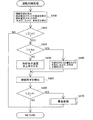
図4は、第2実施例の運転制御処理の流れを示すフローチャートである。この処理は、燃料電池スタック100による発電中に、制御ユニット90のCPUが実行する処理である。
FIG. 4 is a flowchart showing the flow of the operation control process of the second embodiment. This process is a process executed by the CPU of the
まず、CPUは、歪みセンサ54によって、燃料電池スタック100に加わっている締結荷重Lを検出する。また、圧力センサ85によって、燃料電池スタック100内における冷却水の圧力を検出する(ステップS200)。
First, the CPU detects the fastening load L applied to the
次に、CPUは、歪みセンサ54によって検出された締結荷重Lが、所定範囲内にあるか否かを判断する(ステップS210)。本実施例においても、第1実施例と同様に、所定範囲の上限値、および、下限値として、下限値Lth1、および、上限値Lth2が予め設定されているものとした。
Next, the CPU determines whether or not the fastening load L detected by the
そして、歪みセンサ54によって検出された締結荷重Lが、所定範囲内にある場合には(S210:YES)、CPUは、この運転制御処理を終了する。一方、歪みセンサ54によって検出された締結荷重Lが、下限値Lth1以下である場合には(S210:L≦Lth1)、CPUは、循環ポンプ81の出力を増加させて、燃料電池スタック100内の冷却水の圧力を増加させる(ステップS220)。なお、冷却水の圧力の増加量、すなわち、循環ポンプ81の出力の増加量は、任意に設定可能である。こうすることによって、燃料電池スタック100を構成する部材のクリープ等によって、上述した締結荷重が経時的に低下した場合に、燃料電池スタック100内の圧力を増加させ、締結荷重を増加させることができる。
If the fastening load L detected by the
また、歪みセンサ54によって検出された締結荷重Lが、上限値Lth2よりも大きい場合には(ステップS210:L>Lth2)、CPUは、循環ポンプ81の出力を減少させて、燃料電池スタック100内の冷却水の圧力を減少させる(ステップS230)。なお、冷却水の圧力の減少量、すなわち、循環ポンプ81の出力の減少量は、任意に設定可能である。こうすることによって、燃料電池スタック100に過剰な締結荷重が加わることによる燃料電池スタック100を構成する部材の早期劣化を抑制することができる。
Further, when the fastening load L detected by the
そして、CPUは、再度、歪みセンサ54によって、締結荷重Lを検出し(ステップS240)、締結荷重Lが上述した所定範囲内にあるか否かを判断する(ステップS250)。そして、歪みセンサ54によって検出された締結荷重Lが所定範囲内にある場合には(ステップS250:YES)、この運転制御処理を終了する。一方、歪みセンサ54によって検出された締結荷重Lが、所定範囲内にない場合には(ステップS250:NO)、警告処理を行い(ステップS260)、運転者に燃料電池スタック100に加わっている締結荷重の異常を警告する。
Then, the CPU again detects the fastening load L by the strain sensor 54 (step S240), and determines whether or not the fastening load L is within the predetermined range described above (step S250). And when the fastening load L detected by the
以上説明した第2実施例の燃料電池システム1000によっても、第1実施例と同様に、比較的簡易な構成で、燃料電池スタック100内の圧力を調整し、燃料電池スタックに加わる締結荷重を調整することができる。
The
C.第3実施例:
第3実施例の燃料電池システム1000の構成は、図1に示した第1実施例の燃料電池システム1000と同じである。以下、第3実施例の運転制御処理について説明する。
C. Third embodiment:
The configuration of the
図5は、第3実施例の運転制御処理の流れを示すフローチャートである。この処理は、燃料電池スタック100による発電中に、制御ユニット90のCPUが実行する処理である。
FIG. 5 is a flowchart showing a flow of operation control processing of the third embodiment. This process is a process executed by the CPU of the
まず、CPUは、歪みセンサ54によって、燃料電池スタック100に加わっている締結荷重Lを検出する。また、温度センサ86によって、燃料電池スタック100内における冷却水の温度を検出する(ステップS300)。
First, the CPU detects the fastening load L applied to the
次に、CPUは、歪みセンサ54によって検出された締結荷重Lが、所定範囲内にあるか否かを判断する(ステップS310)。本実施例においても、第1実施例と同様に、所定範囲の上限値、および、下限値として、下限値Lth1、および、上限値Lth2が予め設定されているものとした。
Next, the CPU determines whether or not the fastening load L detected by the
そして、歪みセンサ54によって検出された締結荷重Lが、所定範囲内にある場合には(S310:YES)、CPUは、この運転制御処理を終了する。一方、歪みセンサ54によって検出された締結荷重Lが、下限値Lth1以下である場合には(S310:L≦Lth1)、CPUは、循環ポンプ81の出力を減少させるとともに、冷却水が、ラジエータ80を通らずに、バイパス配管83を流れるように、三方弁84を切り換え、燃料電池スタック100内の冷却水の温度を上昇させる(ステップS320)。そして、適宜、三方弁84の切り換え等を行い、冷却水の温度を維持する。なお、冷却水の温度の上昇量は、燃料電池スタック100による発電に適した温度範囲内で任意に設定可能である。こうすることによって、燃料電池スタック100を構成する部材のクリープ等によって、上述した締結荷重が経時的に低下した場合に、燃料電池スタック100を構成する部材を熱膨張させ、締結荷重を増加させることができる。
If the fastening load L detected by the
また、歪みセンサ54によって検出された締結荷重Lが、上限値Lth2よりも大きい場合には(ステップS310:L>Lth2)、CPUは、ラジエータ80が備えるファンの出力を増加させて、燃料電池スタック100内の冷却水の温度を低下させる(ステップS230)。そして、適宜、ファンの出力を制御して、冷却水の温度を維持する。なお、冷却水の温度の低下量は、燃料電池スタック100における発電に適した温度範囲内で任意に設定可能である。こうすることによって、燃料電池スタック100に過剰な締結荷重が加わることによる燃料電池スタック100を構成する部材の早期劣化を抑制することができる。
When the fastening load L detected by the
そして、CPUは、再度、歪みセンサ54によって、締結荷重Lを検出し(ステップS340)、締結荷重Lが上述した所定範囲内にあるか否かを判断する(ステップS350)。そして、歪みセンサ54によって検出された締結荷重Lが所定範囲内にある場合には(ステップS350:YES)、この運転制御処理を終了する。一方、歪みセンサ54によって検出された締結荷重Lが、所定範囲内にない場合には(ステップS350:NO)、警告処理を行い(ステップS360)、運転者に燃料電池スタック100に加わっている締結荷重の異常を警告する。
Then, the CPU again detects the fastening load L by the strain sensor 54 (step S340), and determines whether or not the fastening load L is within the predetermined range (step S350). And when the fastening load L detected by the
以上説明した第3実施例の燃料電池システム1000によっても、第1実施例と同様に、比較的簡易な構成で、燃料電池スタック100内の圧力を調整し、燃料電池スタックに加わる締結荷重を調整することができる。
The
D.第4実施例:
第4実施例の燃料電池システム1000の構成は、図1に示した第1実施例の燃料電池システム1000と同じである。以下、第4実施例の運転制御処理について説明する。
D. Fourth embodiment:
The configuration of the
図6は、第4実施例の運転制御処理の流れを示すフローチャートである。この処理は、燃料電池スタック100による発電中に、制御ユニット90のCPUが実行する処理である。
FIG. 6 is a flowchart showing a flow of operation control processing of the fourth embodiment. This process is a process executed by the CPU of the
まず、CPUは、歪みセンサ54によって、燃料電池スタック100に加わっている締結荷重Lを検出する。また、温度センサ42によって、燃料電池スタック100の温度Tを検出する。また、圧力センサ66、および、圧力センサ74によって、燃料電池スタック100内における水素圧、および、空気圧を検出する(ステップS400)。
First, the CPU detects the fastening load L applied to the
次に、CPUは、歪みセンサ54によって検出された締結荷重Lが、所定の下限値Lth1以下であるか否かを判断する(ステップS410)。そして、歪みセンサ54によって検出された締結荷重Lが、下限値Lth1よりも大きい場合には(S410:NO)、CPUは、この運転制御処理を終了する。一方、歪みセンサ54によって検出された締結荷重Lが、下限値Lth1以下である場合には(S410:L≦Lth1)、CPUは、温度センサ42によって検出された燃料電池スタック100の温度が所定の上限値Tth以上であるか否かを判断する(ステップS420)。
Next, the CPU determines whether or not the fastening load L detected by the
そして、温度センサ42によって検出された温度Tが、上限値Tth未満である場合には(ステップS420:NO)、CPUは、循環ポンプ81の出力を減少させるとともに、冷却水が、ラジエータ80を通らずに、バイパス配管83を流れるように、三方弁84を切り換え、燃料電池スタック100内の冷却水の温度を上昇させる(ステップS430)。そして、適宜、三方弁84の切り換え等を行い、冷却水の温度を維持する。なお、冷却水の温度の上昇量は、燃料電池スタック100による発電に適した温度範囲内で任意に設定可能である。こうすることによって、燃料電池スタック100を構成する部材のクリープ等によって、上述した締結荷重が経時的に低下した場合に、燃料電池スタック100を構成する部材を熱膨張させ、締結荷重を増加させることができる。
When the temperature T detected by the
一方、温度センサ42によって検出された温度Tが、上限値Tth以上である場合には(ステップS420:YES)、CPUは、循環ポンプ81の出力を増加させて、燃料電池スタック100内の冷却水の圧力を増加させるとともに、レギュレータ62,65を制御して、燃料電池スタック100内の水素圧を増加させ、また、エアコンプレッサ70の出力、レギュレータ73を制御して、燃料電池スタック100内の空気圧を増加させる(ステップS440)。こうすることによって、燃料電池スタック100を構成する部材のクリープ等によって、上述した締結荷重が経時的に低下した場合に、燃料電池スタック100内の圧力を増加させ、締結荷重を増加させることができる。
On the other hand, when the temperature T detected by the
そして、CPUは、再度、歪みセンサ54によって、締結荷重Lを検出し(ステップS450)、締結荷重Lが下限値Lth1以下であるか否かを判断する(ステップS460)。そして、歪みセンサ54によって検出された締結荷重Lが下限値Lth1よりも大きい場合には(ステップS460:NO)、CPUは、この運転制御処理を終了する。一方、歪みセンサ54によって検出された締結荷重Lが、下限値Lth1以下である場合には(ステップS460:YES)、警告処理を行い(ステップS470)、運転者に燃料電池スタック100に加わっている締結荷重の異常を警告する。
Then, the CPU again detects the fastening load L by the strain sensor 54 (step S450), and determines whether or not the fastening load L is equal to or lower than the lower limit value Lth1 (step S460). When the fastening load L detected by the
以上説明した第4実施例の燃料電池システム1000によっても、第1実施例と同様に、比較的簡易な構成で、燃料電池スタック100内の圧力を調整し、燃料電池スタックに加わる締結荷重を調整することができる。
The
E.変形例:
以上、本発明のいくつかの実施の形態について説明したが、本発明はこのような実施の形態になんら限定されるものではなく、その要旨を逸脱しない範囲内において種々なる態様での実施が可能である。例えば、以下のような変形が可能である。
E. Variation:
As mentioned above, although several embodiment of this invention was described, this invention is not limited to such embodiment at all, and implementation in various aspects is possible within the range which does not deviate from the summary. It is. For example, the following modifications are possible.
E1.変形例1:
上記各実施例では、テンションプレート50に設置された歪みセンサ54によって、燃料電池スタック100に加わっている締結荷重を、間接的に検出するものとしたが、本発明は、これに限られない。例えば、燃料電池スタック100において積層されるいずれかの部材間に圧力センサを挟み、この圧力センサによって、燃料電池スタック100に加わっている締結荷重を、直接的に検出するようにしてもよい。
E1. Modification 1:
In each of the above embodiments, the fastening load applied to the
E2.変形例2:
上記実施例では、温度センサ42によって、燃料電池スタック100の温度を、直接的に検出するものとしたが、本発明は、これに限られない。例えば、配管82に、燃料電池スタック100に供給される冷却水の温度を検出する温度センサを設け、この温度センサによって検出された温度と、温度センサ86によって検出された、燃料電池スタック100から排出された冷却水の温度との差に基づいて、燃料電池スタック100の温度を推定するようにしてもよい。
E2. Modification 2:
In the above embodiment, the
E3.変形例3:
上記第1実施例の運転制御では、ステップS120、および、ステップS130において、水素圧、および、空気圧の双方を増減させるものとしたが、本発明は、これに限られず、水素圧、および、空気圧のいずれかを増減させるものとしてもよい。ただし、水素圧、および、空気圧の双方を増減させることによって、セル40が備える膜電極接合体の両面における圧力差を小さくし、膜電極接合体の破損を抑制することができる。
E3. Modification 3:
In the operation control of the first embodiment, in steps S120 and S130, both the hydrogen pressure and the air pressure are increased or decreased. However, the present invention is not limited to this, and the hydrogen pressure and the air pressure are increased. It is good also as what increases or decreases any of these. However, by increasing or decreasing both the hydrogen pressure and the air pressure, the pressure difference between both surfaces of the membrane electrode assembly provided in the
なお、ステップS120において、水素圧、および、空気圧のいずれかを増加させる場合には、水素圧を増加させるよりも、空気圧を増加させる方が好ましい。こうすることによって、カソードからの水(生成水)の排出が抑制されるため、電解質膜が膨潤し、締結荷重が増加する。これらは、第4実施例の運転制御のステップS440についても同様である。 In step S120, when increasing either the hydrogen pressure or the air pressure, it is preferable to increase the air pressure rather than increasing the hydrogen pressure. By doing so, discharge of water (product water) from the cathode is suppressed, so that the electrolyte membrane swells and the fastening load increases. The same applies to step S440 of the operation control of the fourth embodiment.
E4.変形例4:
上記第1ないし第4実施例における運転制御処理を、適宜、組み合わせたり、一部を省略したりしてもよい。
E4. Modification 4:
The operation control processes in the first to fourth embodiments may be appropriately combined or a part thereof may be omitted.
1000…燃料電池システム
100…燃料電池スタック
10a,10b…エンドプレート
20a,20b…絶縁板
30a,30b…集電板
40…セル
42…温度センサ
50…テンションプレート
52…ボルト
54…歪みセンサ
60…水素タンク
61…シャットバルブ
62…レギュレータ
63…配管
64…排出配管
65…レギュレータ
66…圧力センサ
70…エアコンプレッサ
71…配管
72…排出配管
73…レギュレータ
74…圧力センサ
80…ラジエータ
81…循環ポンプ
82…配管
83…バイパス配管
84…三方弁
85…圧力センサ
86…温度センサ
90…制御ユニット
DESCRIPTION OF
Claims (10)
燃料ガスと酸化剤ガスとの電気化学反応によって発電するセルを複数積層させるとともに、前記セルの積層方向に所定の締結荷重が加えられた燃料電池スタックと、
前記締結荷重を検出する締結荷重検出部と、
前記検出された締結荷重に基づいて、前記燃料電池スタック内における前記燃料ガス、および、前記酸化剤ガスのうちの少なくとも一方の圧力を制御する圧力制御部と、
を備える燃料電池システム。 A fuel cell system,
A fuel cell stack in which a plurality of cells that generate power by an electrochemical reaction between a fuel gas and an oxidant gas are stacked, and a predetermined fastening load is applied in the stacking direction of the cells,
A fastening load detector for detecting the fastening load;
A pressure control unit that controls the pressure of at least one of the fuel gas and the oxidant gas in the fuel cell stack based on the detected fastening load;
A fuel cell system comprising:
前記圧力制御部は、前記検出された締結荷重が所定値以下であるときに、前記燃料電池スタック内における前記燃料ガス、および、前記酸化剤ガスのうちの少なくとも一方の圧力を増加させる、
燃料電池システム。 The fuel cell system according to claim 1, wherein
The pressure control unit increases the pressure of at least one of the fuel gas and the oxidant gas in the fuel cell stack when the detected fastening load is a predetermined value or less;
Fuel cell system.
前記圧力制御部は、前記検出された締結荷重が所定値以下であるときに、前記燃料電池スタック内における前記燃料ガス、および、前記酸化剤ガスの双方の圧力を増加させる、
燃料電池システム。 The fuel cell system according to claim 2, wherein
The pressure control unit increases the pressure of both the fuel gas and the oxidant gas in the fuel cell stack when the detected fastening load is a predetermined value or less;
Fuel cell system.
燃料ガスと酸化剤ガスとの電気化学反応によって発電するセルを複数積層させるとともに、前記セルの積層方向に所定の締結荷重が加えられた燃料電池スタックと、
前記燃料電池スタックに冷却媒体を流すことによって、前記燃料電池スタックを冷却する冷却システムと、
前記締結荷重を検出する締結荷重検出部と、
前記検出された締結荷重に基づいて、前記燃料電池スタック内における前記冷却媒体の圧力を制御する冷却媒体圧力制御部と、
を備える燃料電池システム。 A fuel cell system,
A fuel cell stack in which a plurality of cells that generate power by an electrochemical reaction between a fuel gas and an oxidant gas are stacked, and a predetermined fastening load is applied in the stacking direction of the cells,
A cooling system for cooling the fuel cell stack by flowing a cooling medium through the fuel cell stack;
A fastening load detector for detecting the fastening load;
A coolant pressure control unit for controlling the pressure of the coolant in the fuel cell stack based on the detected fastening load;
A fuel cell system comprising:
前記冷却媒体圧力制御部は、前記検出された締結荷重が所定値以下であるときに、前記燃料電池スタック内における前記冷却媒体の圧力を増加させる、
燃料電池システム。 The fuel cell system according to claim 4, wherein
The cooling medium pressure control unit increases the pressure of the cooling medium in the fuel cell stack when the detected fastening load is a predetermined value or less;
Fuel cell system.
燃料ガスと酸化剤ガスとの電気化学反応によって発電するセルを複数積層させるとともに、前記セルの積層方向に所定の締結荷重が加えられた燃料電池スタックと、
前記燃料電池スタックに冷却媒体を流すことによって、前記燃料電池スタックを冷却する冷却システムと、
前記締結荷重を検出する締結荷重検出部と、
前記検出された締結荷重に基づいて、前記燃料電池スタックに流す前記冷却媒体の温度を制御する冷却媒体温度制御部と、
を備える燃料電池システム。 A fuel cell system,
A fuel cell stack in which a plurality of cells that generate power by an electrochemical reaction between a fuel gas and an oxidant gas are stacked, and a predetermined fastening load is applied in the stacking direction of the cells,
A cooling system for cooling the fuel cell stack by flowing a cooling medium through the fuel cell stack;
A fastening load detector for detecting the fastening load;
A cooling medium temperature control unit for controlling the temperature of the cooling medium flowing through the fuel cell stack based on the detected fastening load;
A fuel cell system comprising:
前記冷却媒体温度制御部は、前記検出された締結荷重が所定値以下であるときに、前記燃料電池スタック内における前記冷却媒体の温度を上昇させる、
燃料電池システム。 The fuel cell system according to claim 6, wherein
The cooling medium temperature control unit increases the temperature of the cooling medium in the fuel cell stack when the detected fastening load is equal to or less than a predetermined value;
Fuel cell system.
前記燃料電池システムは、燃料ガスと酸化剤ガスとの電気化学反応によって発電するセルを複数積層させるとともに、前記セルの積層方向に所定の締結荷重が加えられた燃料電池スタックを備えており、
前記制御方法は、
前記締結荷重を検出する締結荷重検出工程と、
前記検出された締結荷重に基づいて、前記燃料電池スタック内における前記燃料ガス、および、前記酸化剤ガスのうちの少なくとも一方の圧力を制御する圧力制御工程と、
を備える制御方法。 A control method for a fuel cell system, comprising:
The fuel cell system includes a fuel cell stack in which a plurality of cells that generate power by an electrochemical reaction between a fuel gas and an oxidant gas are stacked, and a predetermined fastening load is applied in the stacking direction of the cells,
The control method is:
A fastening load detection step of detecting the fastening load;
A pressure control step of controlling the pressure of at least one of the fuel gas and the oxidant gas in the fuel cell stack based on the detected fastening load;
A control method comprising:
前記燃料電池システムは、
燃料ガスと酸化剤ガスとの電気化学反応によって発電するセルを複数積層させるとともに、前記セルの積層方向に所定の締結荷重が加えられた燃料電池スタックと、
前記燃料電池スタックに冷却媒体を流すことによって、前記燃料電池スタックを冷却する冷却システムと、を備えており、
前記制御方法は、
前記締結荷重を検出する締結荷重検出工程と、
前記検出された締結荷重に基づいて、前記燃料電池スタック内における前記冷却媒体の圧力を制御する冷却媒体圧力制御工程と、
を備える制御方法。 A control method for a fuel cell system, comprising:
The fuel cell system includes:
A fuel cell stack in which a plurality of cells that generate power by an electrochemical reaction between a fuel gas and an oxidant gas are stacked, and a predetermined fastening load is applied in the stacking direction of the cells,
A cooling system that cools the fuel cell stack by flowing a cooling medium through the fuel cell stack, and
The control method is:
A fastening load detection step of detecting the fastening load;
A cooling medium pressure control step for controlling the pressure of the cooling medium in the fuel cell stack based on the detected fastening load;
A control method comprising:
前記燃料電池システムは、
燃料ガスと酸化剤ガスとの電気化学反応によって発電するセルを複数積層させるとともに、前記セルの積層方向に所定の締結荷重が加えられた燃料電池スタックと、
前記燃料電池スタックに冷却媒体を流すことによって、前記燃料電池スタックを冷却する冷却システムと、を備えており、
前記制御方法は、
前記締結荷重を検出する締結荷重検出工程と、
前記検出された締結荷重に基づいて、前記燃料電池スタックに流す前記冷却媒体の温度を制御する冷却媒体温度制御工程と、
を備える制御方法。 A control method for a fuel cell system, comprising:
The fuel cell system includes:
A fuel cell stack in which a plurality of cells that generate power by an electrochemical reaction between a fuel gas and an oxidant gas are stacked, and a predetermined fastening load is applied in the stacking direction of the cells,
A cooling system that cools the fuel cell stack by flowing a cooling medium through the fuel cell stack, and
The control method is:
A fastening load detection step of detecting the fastening load;
A cooling medium temperature control step for controlling the temperature of the cooling medium flowing through the fuel cell stack based on the detected fastening load;
A control method comprising:
Priority Applications (1)
| Application Number | Priority Date | Filing Date | Title |
|---|---|---|---|
| JP2006321743A JP2008135331A (en) | 2006-11-29 | 2006-11-29 | Fuel cell system, and control method of fuel cell system |
Applications Claiming Priority (1)
| Application Number | Priority Date | Filing Date | Title |
|---|---|---|---|
| JP2006321743A JP2008135331A (en) | 2006-11-29 | 2006-11-29 | Fuel cell system, and control method of fuel cell system |
Publications (1)
| Publication Number | Publication Date |
|---|---|
| JP2008135331A true JP2008135331A (en) | 2008-06-12 |
Family
ID=39560032
Family Applications (1)
| Application Number | Title | Priority Date | Filing Date |
|---|---|---|---|
| JP2006321743A Pending JP2008135331A (en) | 2006-11-29 | 2006-11-29 | Fuel cell system, and control method of fuel cell system |
Country Status (1)
| Country | Link |
|---|---|
| JP (1) | JP2008135331A (en) |
Cited By (3)
| Publication number | Priority date | Publication date | Assignee | Title |
|---|---|---|---|---|
| JP2010157364A (en) * | 2008-12-26 | 2010-07-15 | Toyota Motor Corp | Method of manufacturing fuel cell stack |
| US8673516B2 (en) | 2009-11-25 | 2014-03-18 | Hyundai Motor Company | Surface pressure controlling device for fuel cell stack |
| JP6134832B1 (en) * | 2016-03-30 | 2017-05-24 | 東京瓦斯株式会社 | Fuel cell system |
-
2006
- 2006-11-29 JP JP2006321743A patent/JP2008135331A/en active Pending
Cited By (4)
| Publication number | Priority date | Publication date | Assignee | Title |
|---|---|---|---|---|
| JP2010157364A (en) * | 2008-12-26 | 2010-07-15 | Toyota Motor Corp | Method of manufacturing fuel cell stack |
| US8673516B2 (en) | 2009-11-25 | 2014-03-18 | Hyundai Motor Company | Surface pressure controlling device for fuel cell stack |
| JP6134832B1 (en) * | 2016-03-30 | 2017-05-24 | 東京瓦斯株式会社 | Fuel cell system |
| JP2017183033A (en) * | 2016-03-30 | 2017-10-05 | 東京瓦斯株式会社 | Fuel battery system |
Similar Documents
| Publication | Publication Date | Title |
|---|---|---|
| JP5083587B2 (en) | Fuel cell system and temperature adjustment method thereof | |
| JP4432958B2 (en) | Mobile body equipped with a fuel cell | |
| US9070914B2 (en) | Method of controlling water content of fuel cell and fuel cell system | |
| KR101724846B1 (en) | Operation control method of fuel cell system | |
| JP2009110806A (en) | Fuel cell system, and starting control method of fuel cell system | |
| JP2006351408A (en) | Fuel cell system | |
| JP2007280827A (en) | Temperature control system for fuel cell | |
| JP5141937B2 (en) | FUEL CELL SYSTEM AND FUEL CELL STATE DIAGNOSIS METHOD | |
| JP2009076243A (en) | Fuel cell system | |
| WO2009104368A1 (en) | Fuel cell system and fuel cell system control method | |
| KR20080067381A (en) | Fuel cell system and its operation stop method | |
| JP4144321B2 (en) | Fuel cell system | |
| JP4426892B2 (en) | Fuel cell system | |
| JP5348882B2 (en) | Fuel cell system | |
| JP2008135331A (en) | Fuel cell system, and control method of fuel cell system | |
| JP2019197690A (en) | Activating method for fuel cell | |
| CA2889414A1 (en) | Fuel cell system and control method thereof | |
| JP2009016082A (en) | Fuel cell system | |
| JP2011258497A (en) | Fuel cell system mounted on mobile body and control method of fuel cell system | |
| JP5287368B2 (en) | Fuel cell system | |
| JP2013218923A (en) | Fuel cell system and fuel cell system activation method | |
| JP4984546B2 (en) | Fuel cell system | |
| US11626603B2 (en) | Fuel cell system | |
| US20230378498A1 (en) | Fuel cell system | |
| JP2010015733A (en) | Fuel cell system and compressed air supply device |