JP2009198400A - Cooling structure and method of control rod drive unit and nuclear reactor - Google Patents
Cooling structure and method of control rod drive unit and nuclear reactor Download PDFInfo
- Publication number
- JP2009198400A JP2009198400A JP2008042042A JP2008042042A JP2009198400A JP 2009198400 A JP2009198400 A JP 2009198400A JP 2008042042 A JP2008042042 A JP 2008042042A JP 2008042042 A JP2008042042 A JP 2008042042A JP 2009198400 A JP2009198400 A JP 2009198400A
- Authority
- JP
- Japan
- Prior art keywords
- housing
- control rod
- cooling
- exhaust duct
- cooling air
- Prior art date
- Legal status (The legal status is an assumption and is not a legal conclusion. Google has not performed a legal analysis and makes no representation as to the accuracy of the status listed.)
- Withdrawn
Links
Images


Classifications
-
- G—PHYSICS
- G21—NUCLEAR PHYSICS; NUCLEAR ENGINEERING
- G21C—NUCLEAR REACTORS
- G21C7/00—Control of nuclear reaction
- G21C7/06—Control of nuclear reaction by application of neutron-absorbing material, i.e. material with absorption cross-section very much in excess of reflection cross-section
- G21C7/08—Control of nuclear reaction by application of neutron-absorbing material, i.e. material with absorption cross-section very much in excess of reflection cross-section by displacement of solid control elements, e.g. control rods
- G21C7/12—Means for moving control elements to desired position
- G21C7/14—Mechanical drive arrangements
-
- G—PHYSICS
- G21—NUCLEAR PHYSICS; NUCLEAR ENGINEERING
- G21C—NUCLEAR REACTORS
- G21C7/00—Control of nuclear reaction
- G21C7/06—Control of nuclear reaction by application of neutron-absorbing material, i.e. material with absorption cross-section very much in excess of reflection cross-section
- G21C7/08—Control of nuclear reaction by application of neutron-absorbing material, i.e. material with absorption cross-section very much in excess of reflection cross-section by displacement of solid control elements, e.g. control rods
-
- Y—GENERAL TAGGING OF NEW TECHNOLOGICAL DEVELOPMENTS; GENERAL TAGGING OF CROSS-SECTIONAL TECHNOLOGIES SPANNING OVER SEVERAL SECTIONS OF THE IPC; TECHNICAL SUBJECTS COVERED BY FORMER USPC CROSS-REFERENCE ART COLLECTIONS [XRACs] AND DIGESTS
- Y02—TECHNOLOGIES OR APPLICATIONS FOR MITIGATION OR ADAPTATION AGAINST CLIMATE CHANGE
- Y02E—REDUCTION OF GREENHOUSE GAS [GHG] EMISSIONS, RELATED TO ENERGY GENERATION, TRANSMISSION OR DISTRIBUTION
- Y02E30/00—Energy generation of nuclear origin
- Y02E30/30—Nuclear fission reactors
Abstract
Description
本発明は、原子炉容器の上部に配置されて炉心に対して制御棒を出し入れする制御棒駆動装置の冷却構造及び方法、並びに、この制御棒駆動装置を有する原子炉に関するものである。 The present invention relates to a cooling structure and method for a control rod drive device that is arranged on the upper part of a reactor vessel and inserts and removes control rods into and from a reactor core, and to a nuclear reactor having the control rod drive device.
加圧水型原子炉(PWR:Pressurized Water Reactor)では、軽水を原子炉冷却材及び中性子減速材として使用している。そして、一次系全体にわたって沸騰しない高温高圧水とし、この高温高圧水を蒸気発生器に送って熱交換により蒸気を発生させ、この蒸気をタービン発電機へ送って発電している。 In a pressurized water reactor (PWR), light water is used as a reactor coolant and a neutron moderator. And it is set as the high temperature / high pressure water which does not boil over the whole primary system, this high temperature / high pressure water is sent to a steam generator, steam is generated by heat exchange, and this steam is sent to a turbine generator to generate electricity.
このような加圧水型原子炉では、炉心内で生成される中性子を制御棒により吸収することで、その中性子数を調整し、原子炉出力を制御している。そのため、この制御棒は、予め炉心を構成する燃料集合体の内部に分散して組み込まれており、一括して制御される。複数の制御棒は、原子炉容器の上部の配置された制御棒駆動装置(CRDM:control rod drive mechanism)により炉心に対して出し入れされる。 In such a pressurized water reactor, neutrons generated in the core are absorbed by a control rod, thereby adjusting the number of neutrons and controlling the reactor output. For this reason, the control rods are distributed and incorporated in advance in the fuel assemblies constituting the reactor core, and are controlled collectively. The plurality of control rods are taken in and out of the core by a control rod drive mechanism (CRDM) arranged at the top of the reactor vessel.
加圧水型原子炉用の制御棒駆動装置としては、一般に、磁気式ジャッキが多く適用される。この磁気式ジャッキは、中央の案内管内に駆動軸が配設され、案内管の下部に固定つかみ磁極、固定つかみばね、固定ラッチ機構などが設けられ、固定つかみ磁極の周辺に固定つかみコイルが配置される一方、上部にリフト磁極、可動つかみばね、可動つかみ磁極、可動ラッチ機構などが設けられている。そして、リフト磁極の周辺にリフトコイルが配置され、可動つかみ磁極の周辺に可動つかみコイルが配置され、制御棒を上下に駆動可能となっている。 In general, a magnetic jack is often used as a control rod driving device for a pressurized water reactor. This magnetic jack has a drive shaft in the center guide tube, a fixed grip magnetic pole, a fixed grip spring, and a fixed latch mechanism at the lower part of the guide tube, and a fixed grip coil around the fixed grip magnetic pole. On the other hand, a lift magnetic pole, a movable gripping spring, a movable gripping magnetic pole, a movable latch mechanism, and the like are provided on the top. A lift coil is disposed around the lift magnetic pole, a movable grip coil is disposed around the movable grip magnetic pole, and the control rod can be driven up and down.
この場合、制御棒駆動装置に用いられるコイルは、通電により高温となることから常時冷却する必要がある。制御棒駆動装置の冷却装置としては、下記特許文献1に記載されたものがある。この特許文献1に記載された制御棒駆動機構の冷却方法は、換気ファンにより外部空気をシュラウドの上部から内部に取り入れ、制御棒駆動機構を冷却した後、下部の空気ポートから外部に排出するものである。 In this case, since the coil used for the control rod drive device becomes high temperature when energized, it must be constantly cooled. As a cooling device for the control rod driving device, there is one described in Patent Document 1 below. The cooling method of the control rod drive mechanism described in this Patent Document 1 is a method in which outside air is taken into the shroud from the upper part by a ventilation fan, the control rod drive mechanism is cooled, and then discharged from the lower air port to the outside. It is.
ところが、上述した従来の制御棒駆動機構の冷却方法では、換気ファンにより外部空気をシュラウドの上部から内部に強制的に押し込み、制御棒駆動機構側に流して冷却させている。そして、制御棒駆動機構側を冷却してから更に下方に流し、下部の空気ポートから外部に押し出している。この場合、冷却空気の流れは上から下へとなり、制御棒駆動機構を冷却して高温となった空気を更に下方に流して排出することが困難となる。そのため、シュラウド内で冷却空気が効率良く循環せず、制御棒駆動機構の冷却効率が低下してしまうという問題がある。 However, in the conventional cooling method for the control rod driving mechanism described above, the outside air is forced into the shroud from the upper part by the ventilation fan, and is cooled by flowing to the control rod driving mechanism side. Then, after cooling the control rod drive mechanism side, it flows further downward and is pushed out from the lower air port. In this case, the flow of the cooling air is from top to bottom, and it becomes difficult to cool the control rod drive mechanism and cause the air that has become hot to flow further downward. Therefore, there is a problem that the cooling air does not circulate efficiently in the shroud and the cooling efficiency of the control rod drive mechanism is lowered.
本発明は上述した課題を解決するものであり、制御棒駆動装置の冷却効率の向上を図る制御棒駆動装置の冷却構造及び方法並びに原子炉を提供することを目的とする。 The present invention solves the above-described problems, and an object of the present invention is to provide a cooling structure and method for a control rod drive device and a nuclear reactor that improve the cooling efficiency of the control rod drive device.
上記の目的を達成するための請求項1の発明の制御棒駆動装置の冷却構造は、原子炉容器の上部に配置されて磁気式ジャッキにより炉心に対して制御棒を出し入れする制御棒駆動装置の冷却構造において、前記原子炉容器の上部に固定されて前記磁気式ジャッキを収容するハウジングと、該ハウジング内に冷却空気を取り入れる吸気部と、前記吸気部と前記ハウジングの周方向に並んで配置されて該ハウジング内の冷却空気を下部の第1吸入口から吸入して上方に導く第1排気ダクトと、前記吸気部の下方に配置されて前記ハウジング内の冷却空気を第2吸入口から吸入して前記第1排気ダクトに導く第2排気ダクトと、前記ハウジングの上部に設けられて前記第1排気ダクト内の冷却空気を外部に排出する排出部と、を備えることを特徴とするものである。 In order to achieve the above object, a cooling structure for a control rod drive device according to the first aspect of the present invention is a control rod drive device that is arranged at the top of a reactor vessel and that is inserted into and removed from a reactor core by a magnetic jack. In the cooling structure, the housing is fixed to the upper part of the reactor vessel and accommodates the magnetic jack, the intake portion for taking cooling air into the housing, and the intake portion and the housing are arranged side by side in the circumferential direction. A first exhaust duct that sucks cooling air in the housing from the lower first suction port and guides it upward, and is disposed below the suction portion to suck cooling air in the housing from the second suction port. A second exhaust duct that leads to the first exhaust duct, and a discharge portion that is provided at an upper portion of the housing and discharges the cooling air in the first exhaust duct to the outside. Is shall.
請求項2の発明の制御棒駆動装置の冷却構造では、前記ハウジングは、上下方向に沿う構造体が周方向に所定間隔で複数並設され、前記第2排気ダクトは、前記構造体を貫通して前記第1排気ダクトに連通することを特徴としている。 In the cooling structure of the control rod drive device according to the second aspect of the present invention, the housing includes a plurality of structures along the vertical direction arranged in parallel at predetermined intervals in the circumferential direction, and the second exhaust duct passes through the structure. And communicating with the first exhaust duct.
請求項3の発明の制御棒駆動装置の冷却構造では、前記構造体は、中空形状をなし、前記ハウジング内の冷却空気を吸入する第3吸入口が設けられると共に、貫通孔を通して前記第2排気ダクトに連通することを特徴としている。 In the cooling structure of the control rod drive device according to the invention of claim 3, the structure has a hollow shape, is provided with a third suction port for sucking the cooling air in the housing, and is provided with the second exhaust through the through hole. It is characterized by communicating with the duct.
請求項4の発明の制御棒駆動装置の冷却構造では、前記第2排気ダクトは、前記ハウジングの内部に突出する突出部を有し、該突出部に前記第2吸入口が設けられることを特徴としている。 In the cooling structure for a control rod drive device according to a fourth aspect of the present invention, the second exhaust duct has a projecting portion projecting into the housing, and the projecting portion is provided with the second suction port. It is said.
請求項5の発明の制御棒駆動装置の冷却構造では、前記第1吸入口に、冷却空気が流通する空気量を調整する流量調整部材が設けられることを特徴としている。 In the cooling structure of the control rod drive device according to the fifth aspect of the present invention, the first suction port is provided with a flow rate adjusting member for adjusting the amount of air through which the cooling air flows.
請求項6の発明の制御棒駆動装置の冷却構造では、前記第2排気ダクトに、冷却空気が流通する空気量を調整する流量調整部材が設けられることを特徴としている。 In the cooling structure for the control rod drive device according to the sixth aspect of the invention, the second exhaust duct is provided with a flow rate adjusting member for adjusting the amount of air through which the cooling air flows.
請求項7の発明の制御棒駆動装置の冷却構造では、前記ハウジングに、前記吸気部の下方に位置して開閉自在な作業用開口部が設けられ、該作業用開口部の下方に前記第2吸入口が設けられることを特徴としている。 In the cooling structure for the control rod drive device according to the seventh aspect of the present invention, the housing is provided with a work opening that can be opened and closed located below the air intake, and the second opening is provided below the work opening. A suction port is provided.
請求項8の発明の制御棒駆動装置の冷却構造では、前記排出部に排気ファンが設けられることを特徴としている。 In the cooling structure for the control rod drive device according to the eighth aspect of the present invention, an exhaust fan is provided in the discharge portion.
また、請求項9の発明の制御棒駆動装置の冷却方法は、原子炉容器の上部に配置されて磁気式ジャッキにより炉心に対して制御棒を出し入れする制御棒駆動装置の冷却方法において、前記磁気式ジャッキを収容するハウジングの側壁上部から内部に冷却空気を取り入れ、冷却空気を下降させながら前記磁気式ジャッキを冷却した後、前記ハウジングの側壁下部の全周から内部の冷却空気を排気ダクトに取り出し、該排気ダクトを通して上昇させた後、排気ファンにより外部に排出する、ことを特徴とするものである。 According to a ninth aspect of the present invention, there is provided a cooling method for a control rod drive device according to the present invention, wherein the control rod drive device is disposed on an upper part of a nuclear reactor vessel and the control rod is inserted into and removed from the core by a magnetic jack. Cooling air is taken into the housing from the upper part of the side wall of the housing containing the jack, and the magnetic jack is cooled while lowering the cooling air, and then the cooling air inside is taken out from the entire circumference of the lower part of the side wall of the housing to the exhaust duct. Then, the air is raised through the exhaust duct and then discharged to the outside by an exhaust fan.
請求項10の発明の制御棒駆動装置の冷却方法では、前記吸気部と前記ハウジングの周方向に並んで前記排気ダクトが配置され、前記磁気式ジャッキを冷却した冷却空気を、前記排気ダクトの下部に設けられた第1吸入口から吸入すると共に、前記吸気部の下方に設けられた第2吸入口から吸入し、前記排気ダクトを通して上昇させて排出することを特徴としている。 In the cooling method for the control rod drive device according to the invention of claim 10, the exhaust duct is arranged side by side in the circumferential direction of the intake portion and the housing, and the cooling air that has cooled the magnetic jack is supplied to the lower portion of the exhaust duct. Inhalation is performed from a first suction port provided in the suction port, suction is performed from a second suction port provided below the suction unit, and the gas is lifted and discharged through the exhaust duct.
また、請求項11の発明の原子炉は、原子炉容器と、該原子炉容器内に配置される炉心槽と、該炉心槽内に配置される炉心と、該炉心を制御する複数の制御棒と、前記原子炉容器の上部に配置されて磁気式ジャッキにより前記炉心に対して前記制御棒を出し入れする制御棒駆動装置と、冷却空気により該制御棒駆動装置を冷却する制御棒駆動装置用冷却装置とを備え、原子燃料と冷却材との熱交換により蒸気を発生し、発生蒸気により発電タービンを駆動して発電を行う原子炉において、前記制御棒駆動装置用冷却装置は、前記原子炉容器の上部に固定されて前記磁気式ジャッキを収容するハウジングと、該ハウジング内に冷却空気を取り入れる吸気部と、前記吸気部と前記ハウジングの周方向に並んで配置されて該ハウジング内の冷却空気を下部の第1吸入口から吸入して上方に導く第1排気ダクトと、前記吸気部の下方に配置されて前記ハウジング内の冷却空気を第2吸入口から吸入して前記第1排気ダクトに導く第2排気ダクトと、前記ハウジングの上部に設けられて前記第1排気ダクト内の冷却空気を外部に排出する排出部と、を有することを特徴とするものである。 The reactor of the invention of claim 11 is a reactor vessel, a reactor core tank disposed in the reactor vessel, a reactor core disposed in the reactor core tank, and a plurality of control rods for controlling the reactor core. A control rod driving device that is disposed above the reactor vessel and that moves the control rod into and out of the core by a magnetic jack, and cooling for the control rod driving device that cools the control rod driving device with cooling air A reactor for generating steam by exchanging heat between nuclear fuel and a coolant, and generating power by driving a power generation turbine with the generated steam, wherein the cooling device for the control rod driving device includes the reactor vessel A housing which is fixed to the upper portion of the housing and accommodates the magnetic jack, an intake portion for taking cooling air into the housing, and a cooling air in the housing arranged side by side in the circumferential direction of the intake portion and the housing. A first exhaust duct that is sucked from the lower first suction port and led upward, and a cooling air that is disposed below the suction portion and sucked from the second suction port is led to the first exhaust duct. It has a 2nd exhaust duct, and the discharge part provided in the upper part of the said housing and exhausting the cooling air in the said 1st exhaust duct outside.
請求項1の発明の制御棒駆動装置の冷却構造によれば、ハウジング内に冷却空気を取り入れる吸気部と、ハウジング内の冷却空気を下部の第1吸入口から吸入して上方に導く第1排気ダクトとを、ハウジングの周方向に並んで配置すると共に、吸気部の下方にハウジング内の冷却空気を第2吸入口から吸入して第1排気ダクトに導く第2排気ダクトを配置している。従って、吸気部からハウジング内に取り入れられた冷却空気は、このハウジング内の下部に周方向におけるほとんどの位置に設けられた吸入口から吸入されて外部に排出されることとなる。そのため、冷却空気は、ハウジングの内部をほぼ全域にわたって均一に循環することとなり、複数の磁気式ジャッキを均一に、且つ、効率良く冷却することができ、制御棒駆動装置の冷却効率の向上を図ることができる。 According to the cooling structure of the control rod drive device of the first aspect of the present invention, the intake portion that takes in the cooling air into the housing, and the first exhaust that sucks the cooling air in the housing from the lower first inlet and guides it upward. The ducts are arranged side by side in the circumferential direction of the housing, and a second exhaust duct is disposed below the intake portion and sucks the cooling air in the housing from the second suction port and guides it to the first exhaust duct. Therefore, the cooling air taken into the housing from the intake portion is sucked from the suction ports provided at most positions in the circumferential direction in the lower portion of the housing and discharged to the outside. Therefore, the cooling air circulates almost uniformly throughout the entire interior of the housing, and can cool the plurality of magnetic jacks uniformly and efficiently, thereby improving the cooling efficiency of the control rod drive device. be able to.
請求項2の発明の制御棒駆動装置の冷却構造によれば、ハウジングに上下方向に沿う構造体が周方向に所定間隔で複数並設され、第2排気ダクトがこの構造体を貫通して第1排気ダクトに連通するので、構造体を維持したままで第2排気ダクトを配置することができ、ハウジングの強度低下を抑制しながら、制御棒駆動装置の冷却効率を向上することができる。 According to the cooling structure of the control rod drive device of the second aspect of the present invention, a plurality of structures along the vertical direction are juxtaposed in the circumferential direction at predetermined intervals on the housing, and the second exhaust duct penetrates the structure and is Since it communicates with one exhaust duct, the second exhaust duct can be arranged while maintaining the structure, and the cooling efficiency of the control rod drive device can be improved while suppressing a decrease in the strength of the housing.
請求項3の発明の制御棒駆動装置の冷却構造によれば、構造体を中空形状とし、ハウジング内の冷却空気を吸入する第3吸入口を設けると共に、貫通孔を通して第2排気ダクトに連通するので、構造体を維持したままで第2排気ダクトを配置することができると共に、吸入口を設けることでハウジング内での冷却空気の滞留を抑制することができ、ハウジングの強度低下を抑制しながら、制御棒駆動装置の冷却効率を向上することができる。 According to the cooling structure of the control rod drive device of the third aspect of the invention, the structure has a hollow shape, the third suction port for sucking the cooling air in the housing is provided, and communicates with the second exhaust duct through the through hole. Therefore, while maintaining the structure, the second exhaust duct can be arranged, and by providing the suction port, the retention of the cooling air in the housing can be suppressed, and the strength reduction of the housing can be suppressed. The cooling efficiency of the control rod driving device can be improved.
請求項4の発明の制御棒駆動装置の冷却構造によれば、第2排気ダクトにハウジングの内部に突出する突出部を設け、この突出部に第2吸入口を設けるので、この第2吸入口の開口面積を十分に確保することで、ハウジング内から第2排気ダクトへの冷却空気の吸入能力を上げることができ、ハウジング内での冷却空気の滞留を抑制し、制御棒駆動装置の冷却効率を向上することができる。 According to the cooling structure of the control rod drive device of the fourth aspect of the present invention, the second exhaust duct is provided with the projecting portion projecting into the housing, and the projecting portion is provided with the second suction port. By sufficiently securing the opening area of the housing, it is possible to increase the intake capacity of the cooling air from the housing to the second exhaust duct, suppress the retention of the cooling air in the housing, and the cooling efficiency of the control rod drive device Can be improved.
請求項5の発明の制御棒駆動装置の冷却構造によれば、第1吸入口に冷却空気が流通する空気量を調整する流量調整部材を設けるので、第1吸入口から第1排気ダクトに吸入される冷却空気量と、第2吸入口から第2排気ダクトに吸入される冷却空気量とを調整することで、ハウジング内部に効率良く冷却空気を循環することができる。 According to the cooling structure of the control rod drive device of the fifth aspect of the present invention, since the flow rate adjusting member for adjusting the amount of air flowing through the cooling air is provided at the first suction port, the suction is sucked from the first suction port into the first exhaust duct. The cooling air can be efficiently circulated inside the housing by adjusting the amount of cooling air to be adjusted and the amount of cooling air sucked into the second exhaust duct from the second suction port.
請求項6の発明の制御棒駆動装置の冷却構造によれば、第2排気ダクトに冷却空気が流通する空気量を調整する流量調整部材を設けるので、第1吸入口から第1排気ダクトに吸入される冷却空気量と、第2吸入口から第2排気ダクトに吸入される冷却空気量とを調整することで、ハウジング内部に効率良く冷却空気を循環することができる。 According to the cooling structure of the control rod drive device of the sixth aspect of the present invention, the flow rate adjusting member for adjusting the amount of air flowing through the cooling air is provided in the second exhaust duct, so that the suction from the first suction port to the first exhaust duct. The cooling air can be efficiently circulated inside the housing by adjusting the amount of cooling air to be adjusted and the amount of cooling air sucked into the second exhaust duct from the second suction port.
請求項7の発明の制御棒駆動装置の冷却構造によれば、ハウジングにおける吸気部の下方に開閉自在な作業用開口部を設け、この作業用開口部の下方に第2吸入口を設けるので、吸気部だけでなく作業用開口部を設けても、ハウジング内の冷却空気は、このハウジング内の下部に周方向におけるほとんどの位置に設けられた吸入口から吸入されて外部に排出されるため、冷却空気はハウジングの内部をほぼ全域にわたって均一に循環することができる。 According to the cooling structure of the control rod drive device of the seventh aspect of the invention, the work opening that can be opened and closed is provided below the intake part in the housing, and the second suction port is provided below the work opening. Even if the working opening as well as the intake portion is provided, the cooling air in the housing is sucked from the suction port provided at most positions in the circumferential direction at the lower part in the housing and discharged to the outside. The cooling air can circulate uniformly in the entire area of the housing.
請求項8の発明の制御棒駆動装置の冷却構造によれば、排出部に排気ファンを設けるので、排気ファンを駆動することで、第1排気ダクト及び第2排気ダクトから各吸入口を通してハウジング内に負圧を付与することで、ハウジング内の冷却空気を強制的に外部に排出することができ、ハウジング内での冷却空気の滞留を抑制し、制御棒駆動装置の冷却効率を向上することができる。 According to the cooling structure of the control rod drive device of the eighth aspect of the present invention, since the exhaust fan is provided in the discharge portion, the exhaust fan is driven, so that the interior of the housing is passed through each intake port from the first exhaust duct and the second exhaust duct. By applying a negative pressure to the housing, the cooling air in the housing can be forcibly discharged to the outside, and the retention of the cooling air in the housing can be suppressed and the cooling efficiency of the control rod drive device can be improved. it can.
また、請求項9の発明の制御棒駆動装置の冷却方法によれば、磁気式ジャッキを収容するハウジングの側壁上部から内部に冷却空気を取り入れ、冷却空気を下降させながら磁気式ジャッキを冷却した後、ハウジングの側壁下部の全周から内部の冷却空気を排気ダクトに取り出し、排気ダクトを通して上昇させた後、排気ファンにより外部に排出するようにしている。従って、冷却空気は、ハウジングの内部をほぼ全域にわたって均一に循環することとなり、複数の磁気式ジャッキを均一に、且つ、効率良く冷却することができ、制御棒駆動装置の冷却効率の向上を図ることができる。 According to the cooling method of the control rod drive device of the ninth aspect of the invention, after cooling air is taken into the inside from the upper part of the side wall of the housing that houses the magnetic jack, and the magnetic jack is cooled while the cooling air is lowered. The internal cooling air is taken out from the entire circumference of the lower part of the side wall of the housing into the exhaust duct, raised through the exhaust duct, and then discharged to the outside by the exhaust fan. Accordingly, the cooling air circulates almost uniformly throughout the interior of the housing, so that the plurality of magnetic jacks can be cooled uniformly and efficiently, and the cooling efficiency of the control rod drive device is improved. be able to.
請求項10の発明の制御棒駆動装置の冷却方法によれば、吸気部とハウジングの周方向に並んで排気ダクトを配置し、磁気式ジャッキを冷却した冷却空気を、排気ダクトの下部に設けられた第1吸入口から吸入すると共に、吸気部の下方に設けられた第2吸入口から吸入し、排気ダクトを通して上昇させて排出するので、ハウジング内部の冷却空気を効率的に排出することができる。 According to the cooling method for the control rod drive device of the tenth aspect of the present invention, the exhaust duct is arranged side by side in the circumferential direction of the intake portion and the housing, and the cooling air for cooling the magnetic jack is provided at the lower portion of the exhaust duct. Since the air is sucked from the first suction port and sucked from the second suction port provided below the suction portion and is lifted and discharged through the exhaust duct, the cooling air inside the housing can be efficiently discharged. .
また、請求項11の発明の原子炉によれば、原子炉容器と炉心槽と炉心と複数の制御棒と制御棒駆動装置と制御棒駆動装置用冷却装置とを備え、この制御棒駆動装置用冷却装置として、ハウジング内に冷却空気を取り入れる吸気部と、ハウジング内の冷却空気を下部の第1吸入口から吸入して上方に導く第1排気ダクトとを、ハウジングの周方向に並んで配置すると共に、吸気部の下方にハウジング内の冷却空気を第2吸入口から吸入して第1排気ダクトに導く第2排気ダクトを配置している。従って、吸気部からハウジング内に取り入れられた冷却空気は、このハウジング内の下部に周方向におけるほとんどの位置に設けられた吸入口から吸入されて外部に排出されることとなる。そのため、冷却空気は、ハウジングの内部をほぼ全域にわたって均一に循環することとなり、複数の磁気式ジャッキを均一に、且つ、効率良く冷却することができ、制御棒駆動装置の冷却効率の向上を図ることができ、その結果、原子炉の高精度な出力制御を可能とすることができる。 According to the reactor of the eleventh aspect of the present invention, the reactor includes a reactor vessel, a core tank, a core, a plurality of control rods, a control rod drive device, and a cooling device for the control rod drive device. As a cooling device, an intake portion that takes cooling air into the housing and a first exhaust duct that draws the cooling air in the housing from the lower first suction port and guides it upward are arranged side by side in the circumferential direction of the housing. At the same time, a second exhaust duct is disposed below the intake portion to draw the cooling air in the housing from the second intake port and guide it to the first exhaust duct. Therefore, the cooling air taken into the housing from the intake portion is sucked from the suction ports provided at most positions in the circumferential direction in the lower portion of the housing and discharged to the outside. Therefore, the cooling air circulates almost uniformly throughout the entire interior of the housing, and can cool the plurality of magnetic jacks uniformly and efficiently, thereby improving the cooling efficiency of the control rod drive device. As a result, high-accuracy power control of the nuclear reactor can be realized.
以下に添付図面を参照して、本発明に係る制御棒駆動装置の冷却構造及び原子炉の好適な実施例を詳細に説明する。なお、この実施例により本発明が限定されるものではない。 Exemplary embodiments of a cooling structure for a control rod drive device and a nuclear reactor according to the present invention will be described below in detail with reference to the accompanying drawings. In addition, this invention is not limited by this Example.
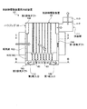
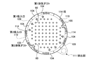
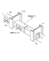
図1は、本発明の実施例1に係る制御棒駆動装置の冷却構造を表す制御棒駆動装置用冷却装置の断面図、図2は、図1のII−II断面図、図3は、図1のIII−III断面図、図4は、実施例1の制御棒駆動装置用冷却装置の斜視概略図、図5は、実施例1の制御棒駆動装置用冷却装置における第2排気ダクトの概略図、図6は、実施例1の加圧水型原子炉を有する原子力発電プラントの概略構成図、図7は、実施例1の加圧水型原子炉を表す縦断面図、図8は、実施例1の加圧水型原子炉における制御棒駆動装置を表す要部断面図である。 1 is a sectional view of a cooling device for a control rod drive device representing a cooling structure of a control rod drive device according to a first embodiment of the present invention, FIG. 2 is a sectional view taken along line II-II in FIG. 1, and FIG. FIG. 4 is a schematic perspective view of a cooling device for a control rod drive device according to the first embodiment, and FIG. 5 is an outline of a second exhaust duct in the cooling device for the control rod drive device according to the first embodiment. FIG. 6 is a schematic configuration diagram of a nuclear power plant having a pressurized water reactor of Example 1, FIG. 7 is a longitudinal sectional view showing the pressurized water reactor of Example 1, and FIG. It is principal part sectional drawing showing the control rod drive device in a pressurized water reactor.
実施例1の原子炉は、軽水を原子炉冷却材及び中性子減速材として使用し、炉心全体にわたって沸騰しない高温高圧水とし、この高温高圧水を蒸気発生器に送って熱交換により蒸気を発生させ、この蒸気をタービン発電機へ送って発電する加圧水型原子炉(PWR:Pressurized Water Reactor)である。 The nuclear reactor of Example 1 uses light water as a reactor coolant and a neutron moderator, and produces high-temperature and high-pressure water that does not boil over the entire core, and sends this high-temperature and high-pressure water to a steam generator to generate steam by heat exchange. This is a pressurized water reactor (PWR) that generates electricity by sending this steam to a turbine generator.
本実施例の加圧水型原子炉を有する原子力発電プラントにおいて、図6に示すように、原子炉格納容器11内には、加圧水型原子炉12及び蒸気発生器13が格納されており、この加圧水型原子炉12と蒸気発生器13とは冷却水配管(冷却材供給配管系)14,15を介して連結されており、冷却水配管14に加圧器16が設けられ、冷却水配管15に冷却水ポンプ15aが設けられている。この場合、減速材及び一次冷却水として軽水を用い、炉心部における一次冷却水の沸騰を抑制するために、一次冷却系統は加圧器16により150〜160気圧程度の高圧状態を維持するように制御している。従って、加圧水型原子炉12にて、燃料(原子燃料)として低濃縮ウランまたはMOXにより一次冷却水として軽水が加熱され、高温の一次冷却水が加圧器16により所定の高圧に維持した状態で冷却水配管14を通して蒸気発生器13に送られる。この蒸気発生器13では、高圧高温の一次冷却水と二次冷却水との間で熱交換が行われ、冷やされた一次冷却水は冷却水配管15を通して加圧水型原子炉12に戻される。
In the nuclear power plant having the pressurized water reactor of the present embodiment, as shown in FIG. 6, a
蒸気発生器13は、蒸気タービン17と冷却水配管18を介して連結されており、この蒸気タービン17は高圧タービン19及び低圧タービン20を有すると共に、発電機21が接続されている。また、高圧タービン19と低圧タービン20との間には、湿分分離加熱器22が設けられており、冷却水配管18から分岐した冷却水分岐配管23が湿分分離加熱器22に連結される一方、高圧タービン19と湿分分離加熱器22は低温再熱管24により連結され、湿分分離加熱器22と低圧タービン20は高温再熱管25により連結されている。更に、蒸気タービン17の低圧タービン20は、復水器26を有しており、この復水器26には冷却水(例えば、海水)を給排する取水管27及び排水管28が連結されている。そして、この復水器26は、冷却水配管29を介して脱気器30に連結されており、この冷却水配管29に復水ポンプ31及び低圧給水加熱器32が設けられている。また、脱気器30は、冷却水配管33を介して蒸気発生器13に連結されており、この冷却水配管33には給水ポンプ34及び高圧給水加熱器35が設けられている。
The
従って、蒸気発生器13にて、高圧高温の一次冷却水と熱交換を行って生成された蒸気は、冷却水配管18を通して蒸気タービン17(高圧タービン19から低圧タービン20)に送られ、この蒸気により蒸気タービン17を駆動して発電機21により発電を行う。このとき、蒸気発生器13からの蒸気は、高圧タービン19を駆動した後、湿分分離加熱器22で蒸気に含まれる湿分が除去されると共に加熱されてから低圧タービン20を駆動する。そして、蒸気タービン17を駆動した蒸気は、復水器26で冷却されて復水となり、低圧給水加熱器32で、例えば、低圧タービン20から抽気した低圧蒸気により加熱され、脱気器30で溶存酸素や不凝結ガス(アンモニアガス)などの不純物が除去された後、高圧給水加熱器35で、例えば、高圧タービン19から抽気した高圧蒸気により加熱された後、蒸気発生器13に戻される。
Therefore, the steam generated by performing heat exchange with the high-pressure and high-temperature primary cooling water in the
また、加圧水型原子炉12において、図7に示すように、原子炉容器41は、その内部に炉内構造物が挿入できるように、原子炉容器本体42とその上部に装着される原子炉容器蓋43により構成されており、この原子炉容器本体42に対して原子炉容器蓋43が開閉可能となっている。原子炉容器本体42は、上部が開口して下部が球面状に閉塞された円筒形状をなし、上部に一次冷却水としての軽水(冷却材)を給排する入口ノズル44及び出口ノズル45が形成されている。
Further, in the
原子炉容器本体42内にて、入口ノズル44及び出口ノズル45より下方には、円筒形状をなす炉心槽46が原子炉容器本体42の内面と所定の隙間をもって配置されており、この炉心槽46の上部には、円板形状をなして図示しない多数の連通孔が形成された上部炉心板47が連結され、下部には、同じく円板形状をなして図示しない多数の連通孔が形成された下部炉心板48が連結されている。そして、原子炉容器本体42内には、炉心槽46の上方に位置して円板形状をなす上部炉心支持板49が固定されており、この上部炉心支持板49から複数の炉心支持ロッド50を介して上部炉心板47、つまり、炉心槽46が吊下げ支持されている。一方、下部炉心板48、つまり、炉心槽46は、原子炉容器本体42の内面に対して複数のラジアルキー52により位置決め保持されている。
Within the reactor vessel
炉心槽46と上部炉心板47と下部炉心板48により炉心53が形成されており、この炉心53には、多数の燃料集合体54が配置されている。この燃料集合体54は、図示しないが、多数の燃料棒が支持格子により格子状に束ねられて構成され、上端部に上部ノズルが固定される一方、下端部に下部ノズルが固定されている。そして、複数の制御棒55は、上端部がまとめられて制御棒クラスタ56となり、燃料集合体54内に挿入可能となっている。上部炉心支持板49には、この上部炉心支持板49を貫通して多数の制御棒クラスタ案内管57が支持されており、下端部が燃料集合体54の制御棒クラスタ56まで延出されている。
A core 53 is formed by the core tank 46, the
原子炉容器41を構成する原子炉容器蓋43の上部には、磁気式ジャッキの制御棒駆動装置58が設けられており、原子炉容器蓋43と一体をなすハウジング59内に収容されている。多数の制御棒クラスタ案内管57の上端部は、制御棒駆動装置58まで延出され、この制御棒駆動装置58から延出されて制御棒クラスタ駆動軸60が、制御棒クラスタ案内管57内を通って燃料集合体54まで延出され、制御棒クラスタ56を把持可能となっている。また、図示しないが、上部炉心支持板49には、この上部炉心支持板49を貫通して多数の炉内計装案内管が支持されており、下端部が燃料集合体54まで延出されており、中性子束を計測できるセンサを挿入可能となっている。
A control jack driving device 58 of a magnetic jack is provided on the upper portion of the
この制御棒駆動装置58は、上下方向に延設されて制御棒クラスタ56に連結されると共に、その表面に複数の周溝を長手方向に等ピッチで配設してなる制御棒クラスタ駆動軸(以下、駆動軸と称する。)60を磁気式ジャッキで上下動させることで、原子炉の出力を制御している。 The control rod drive device 58 extends in the vertical direction and is connected to the control rod cluster 56 and has a control rod cluster drive shaft (having a plurality of circumferential grooves arranged at equal pitches in the longitudinal direction on the surface thereof. Hereinafter, it is referred to as a drive shaft.) The output of the nuclear reactor is controlled by moving 60 up and down with a magnetic jack.
即ち、図8に示すように、駆動軸60は、その表面に複数の周溝60aが長手方向に等ピッチで形成されており、円筒形状をなす駆動軸ハウジング61内に軸方向に移動自在となっている。そして、この駆動軸60の周溝60aの1つに係合離反可能に設けられた固定つかみラッチ62、この固定つかみラッチ62をラッチリンク63及びプランジャ64を介して駆動する固定つかみコイル65を有し、固定つかみラッチ62を周溝60aに係合させることにより駆動軸60を上下方向に保持する保持機構66が設けられている。また、駆動軸60の周溝60aの1つと係合離反可能に設けられた可動つかみラッチ67、この可動つかみラッチ67をラッチリンク68及びプランジャ69を介して駆動する可動つかみコイル70、ラッチリンク68及びプランジャ69を上下方向に移動させる上げコイル71とを有し、駆動軸60を上下動させる駆動機構72が設けられている。
That is, as shown in FIG. 8, the
なお、73は、固定つかみコイル65に励磁される固定取手磁極、74は、可動つかみコイル70に励磁される可動取手磁極、75は、上げコイル71に励磁される上げ磁極である。また、76a〜76cはリターンスプリングである。
例えば、固定つかみコイル65により固定取手磁極73が消磁されて固定つかみラッチ62が駆動軸60の周溝60aから離反される一方、可動つかみコイル70により可動取手磁極74が励磁されて可動つかみラッチ67が駆動軸60の周溝60aに係合された状態から、上げコイル71により上げ磁極75を励磁すると、可動取手磁極74及び可動つかみラッチ67が可動つかみコイル70と共にリターンスプリング76aの付勢力に抗して上げ磁極75側に吸引され、駆動軸60を1ピッチ上昇することができる。
For example, the fixed gripping
次に、固定つかみコイル65により固定取手磁極73が励磁されて固定つかみラッチ62が駆動軸60の周溝60aに係合された後、可動つかみコイル70により可動取手磁極74が消磁されると共に上げコイル71により上げ磁極75が消磁されると、可動つかみラッチ67が駆動軸60の周溝60aから離反され、リターンスプリング76aの付勢力で可動取手磁極74及び可動つかみラッチ67が可動つかみコイル70と共に下降することができる。
Next, after the fixed gripping
そして、可動つかみコイル70により可動取手磁極74が励磁されて可動つかみラッチ67が駆動軸60の周溝60aに係合された後、固定つかみコイル65により固定取手磁極73が消磁されて固定つかみラッチ62が駆動軸60の周溝60aから離反された状態から、上述した動作を繰り返すことで駆動軸60は所定ピッチまで上昇することができる。なお、駆動軸60を下降させるには、上述した動作の逆動作を行えばよいものである。
Then, after the movable gripping
従って、図7に戻り、制御棒駆動装置58により制御棒クラスタ駆動軸60を移動して燃料集合体54に制御棒55を挿入することで、炉心53内での核分裂を制御し、発生した熱エネルギにより原子炉容器41内に充填された軽水が加熱され、高温の軽水が出口ノズル45から排出され、上述したように、蒸気発生器13に送られる。即ち、燃料集合体54を構成する燃料としてのウランまたはプルトニウムが核分裂することで中性子を放出し、減速材及び一次冷却水としての軽水が、放出された高速中性子の運動エネルギを低下させて熱中性子とし、新たな核分裂を起こしやすくすると共に、発生した熱を奪って冷却する。また、制御棒55を燃料集合体54に挿入することで、炉心53内で生成される中性子数を調整し、また、原子炉を緊急に停止するときには炉心53に急速に挿入される。
Therefore, returning to FIG. 7, the control rod drive device 58 moves the control rod
また、原子炉容器41内には、炉心53に対して、その上方に出口ノズル45に連通する上部プレナム81が形成されると共に、下方に下部プレナム82が形成されている。そして、原子炉容器41と炉心槽46との間に入口ノズル44及び下部プレナム82に連通するダウンカマー部83が形成されている。従って、軽水は、4つの入口ノズル44から原子炉容器本体42内に流入し、ダウンカマー部83を下向きに流れ落ちて下部プレナム82に至り、この下部プレナム82の球面状の内面により上向きに案内されて上昇し、下部炉心板48を通過した後、炉心53に流入する。この炉心53に流入した軽水は、炉心53を構成する燃料集合体54から発生する熱エネルギを吸収することで、この燃料集合体54を冷却する一方、高温となって上部炉心板47を通過して上部プレナム81まで上昇し、出口ノズル45を通って排出される。
In the reactor vessel 41, an
このように構成された加圧水型原子炉12にて、本実施例では、制御棒駆動装置58を冷却する冷却装置が設けられている。図1乃至図4に示すように、この制御棒駆動装置用冷却装置101において、ハウジング59は、吸気部102と作業用開口部103と第1排気ダクト104と第2排気ダクト105と第3排気ダクト106とが連結されることで側壁が構成され、上部に天井壁107が連結されて構成されている。そして、このハウジング59の内部に制御棒駆動装置58を構成する複数の磁気式ジャッキが収容されている。この場合、本実施例の冷却装置は、ハウジング59に設けられた後述する排出部111の排気ファン113を駆動することで、外部からハウジング59内に冷却空気を吸い込んで排気する吸込排気式である。
In the
即ち、上部に設けられた第3排気ダクト106は、中空でリング形状をなしている。吸気部102は、外部から冷却空気を取り入れることが可能な開口部であって、各開口部にフィルタが装着されている。作業用開口部103は、点検作業やメンテナンス作業などの際に、作業者がハウジング59内に進入するための開口部であって、不使用時には開閉扉108により閉止され、使用時にこの開閉扉108を開放する。この吸気部102と作業用開口部103は、吸気部102の下方に作業用開口部103が位置するように上下に配置され、ハウジング59の径方向に対向して周方向に均等間隔で2組設けられている。
That is, the
第1排気ダクト104は、ハウジング59内の冷却空気を下部の第1吸入口109から吸入して上方に導くものであって、ハウジング59の上下方向に沿って配設されると共に、周方向に複数並設されている。そして、この第1排気ダクト104は、ハウジング59の周方向において、2組の吸気部102及び作業用開口部103の間に配置されている。つまり、吸気部102及び作業用開口部103と第1排気ダクト104は、ハウジング59の周方向に並んで配置されている。
The
第2排気ダクト105は、吸気部102及び作業用開口部103の下方に配置され、ハウジング59内の冷却空気を第2吸入口110から吸入して第1排気ダクト104に導くものであって、ハウジング59の周方向に沿って配設されている。この場合、実際には、ハウジング59の下端部に、中空でリング形状をなすと共に内周部に多数の吸入口が形成されたダクト部材を配置し、複数の第1排気ダクト104の下端部をこのダクト部材の上面部に連結すると共に内部を連通することで、第1排気ダクト104及び第2排気ダクト105を一体に形成している。つまり、ダクト部材が第1排気ダクト104の一部及び第2排気ダクト105を構成している。
The
ハウジング59の上部には、第1排気ダクト104内の冷却空気を外部に排出する排出部111が設けられている。即ち、第3排気ダクト106の外周部には、連結排気ダクト112が連結され、この連結排気ダクト112に排気ファン113が設けられている。なお、ハウジング59の天井壁107には、制御棒駆動装置58の各磁気式ジャッキが装着される取付孔107aが形成されている。
A
ところで、ハウジング59は、内部に上下方向に沿う柱114が周方向に複数均等間隔で並設されている。この複数の柱114は、構造体として機能し、本実施例では、断面がH形形状をなす鋼材により構成されている。即ち、吸気部102、作業用開口部103、第1排気ダクト104、第2排気ダクト105、第3排気ダクト106などは、この複数の柱114に支持されることで、所定の強度が確保されている。そして、第2排気ダクト105は、この柱114を貫通して第1排気ダクト104に連通している。
By the way, in the
図5に示すように、吸気部102における周方向中間位置にある柱114に対してその周方向両側に第2排気ダクト115(105a,105b)が配置されている。そして、各第2排気ダクト105a,105bの基端部には、ハウジング59内に開口する第2吸入口110a,110bが形成される一方、先端部が複数の柱114を介して第1排気ダクト104まで延出されている。この場合、第2排気ダクト105a,105bの途中に位置する各柱114には、第2排気ダクト105a,105bの流路面積より小さい、実際には、幅の狭い貫通孔114aが形成されている。
As shown in FIG. 5, the second exhaust ducts 115 (105 a and 105 b) are arranged on both sides in the circumferential direction with respect to the
このように構成された制御棒駆動装置用冷却装置101にて、図1乃至図3に示すように、排出部111の排気ファン113が駆動すると、その吸引力が第3排気ダクト106から第1排気ダクト104の第1吸入口109を通してハウジング59内に作用すると共に、吸引力が第3排気ダクト106から第1排気ダクト104を介して第2排気ダクト105の第2吸入口110を通してハウジング59内に作用する。更に、ハウジング59内に作用した吸引力が2つの吸気部102に作用する。
As shown in FIGS. 1 to 3, when the cooling
そのため、外部の空気が冷却空気として各吸気部102からハウジング59内に取り込まれる。各吸気部102からハウジング59内に取り込まれた冷却空気は、このハウジング59内を下降しながら制御棒駆動装置用冷却装置101の各磁気式ジャッキのコイル65,70,71(図8参照)を冷却する。各コイル65,70,71を冷却して温度が上昇した冷却空気は、排出部111の排気ファン113により吸引力が作用する第1吸入口109及び第2吸入口110に吸引され、ハウジング59内から第1吸入口109を通して直接第2排気ダクト105に吸入されると共に、ハウジング59内から第2吸入口110を通して第2排気ダクト105を介して第1排気ダクト104に吸入される。そして、この冷却空気は、各第1排気ダクト104内を上昇して第3排気ダクト106に流れ、連結排気ダクト112から排気ファン113により外部に排出される。
Therefore, external air is taken into the
この場合、各吸気部102からハウジング59内に取り入れられた冷却空気は、このハウジング59内の下部に周方向におけるほとんどの位置に設けられた各吸入口109,110から吸入されて各排気ダクト104,105に流れ込む。そのため、冷却空気は、ハウジング59内をその中央部から外周側へ適正に流動し、内部をほぼ全域にわたって均一に循環することとなり、複数の磁気式ジャッキは、均一に、且つ、効率良く冷却される。
In this case, the cooling air taken into the
このように実施例1の制御棒駆動装置の冷却構造にあっては、原子炉容器41の上部に磁気式ジャッキを収容するハウジング59を固定し、このハウジング59内に冷却空気を取り入れる吸気部102と、吸気部102とハウジング59の周方向に並んでハウジング59内の冷却空気を下部の第1吸入口109から吸入して上方に導く第1排気ダクト104と、吸気部102の下方に配置されてハウジング59内の冷却空気を第2吸入口110から吸入して第1排気ダクト104に導く第2排気ダクト105と、ハウジング59の上部に設けられて第1排気ダクト104内の冷却空気を外部に排出する排出部111とを設けている。
As described above, in the cooling structure of the control rod driving apparatus of the first embodiment, the
従って、吸気部102からハウジング59内に取り入れられた冷却空気は、このハウジング59内の下部に周方向におけるほとんどの位置に設けられた各吸入口109,110から吸入され、各排気ダクト104,105から排出部111を通して外部に排出されることとなる。そのため、冷却空気は、ハウジング59の内部をほぼ全域にわたって均一に循環することとなり、複数の磁気式ジャッキを均一に、且つ、効率良く冷却することができ、制御棒駆動装置58の冷却効率の向上を図ることができる。
Accordingly, the cooling air taken into the
また、実施例1の制御棒駆動装置の冷却構造では、ハウジング59に上下方向に沿う構造体としての柱114を周方向に所定間隔で複数並設し、第2排気ダクト105の流路がこの柱114を貫通して第1排気ダクト104に連通している。従って、柱114を維持したままで第2排気ダクト104を配置することができ、ハウジング59の強度低下を抑制しながら、制御棒駆動装置58の冷却効率を向上することができる。この場合、第2排気ダクト105の途中の柱114には、第2排気ダクト105の流路より流路面積の小さい貫通孔114aを形成しており、柱114の強度低下を極力低下させることができる。
Further, in the cooling structure of the control rod driving device of the first embodiment, a plurality of
また、実施例1の制御棒駆動装置の冷却構造では、ハウジング59における吸気部102の下方に開閉自在な作業用開口部103を設け、この作業用開口部103の下方に第2吸入口110を設けている。従って、吸気部102だけでなく作業用開口部103を設けても、ハウジング59内の冷却空気は、このハウジング59内の下部に周方向におけるほとんどの位置に設けられた各吸入口109,110から吸入されて外部に排出されるため、冷却空気はハウジング59の内部をほぼ全域にわたって均一に循環することができる。
Further, in the cooling structure of the control rod driving device of the first embodiment, the
また、実施例1の制御棒駆動装置の冷却構造では、排出部111に排気ファン113を設けている。従って、排気ファン113を駆動することで、第1排気ダクト104及び第2排気ダクト105から各吸入口109,110を通してハウジング59内に負圧を付与することができる。そのため、ハウジング59内の冷却空気を強制的に外部に排出することができ、ハウジング59内での冷却空気の滞留を抑制し、制御棒駆動装置58の冷却効率を向上することができる。
Further, in the cooling structure of the control rod drive device of the first embodiment, the
また、実施例1の制御棒駆動装置の冷却方法にあっては、磁気式ジャッキを収容するハウジング59の側壁上部から内部に冷却空気を取り入れ、冷却空気を下降させながら磁気式ジャッキを冷却した後、ハウジング59の側壁下部の全周から内部の冷却空気を排気ダクト103,104に取り出し、この排気ダクト103,104を通して上昇させた後、排気ファン113により外部に排出するようにしている。従って、冷却空気は、ハウジング59の内部をほぼ全域にわたって均一に循環することとなり、複数の磁気式ジャッキを均一に、且つ、効率良く冷却することができ、制御棒駆動装置の冷却効率の向上を図ることができる。
Further, in the cooling method of the control rod drive device of the first embodiment, after cooling air is taken into the inside from the upper side wall of the
更に、実施例1の加圧水型原子炉にあっては、原子炉容器41と炉心槽46と炉心53と複数の制御棒55と制御棒駆動装置58と制御棒駆動装置用冷却装置101とを設け、制御棒駆動装置用冷却装置101として、原子炉容器41の上部に磁気式ジャッキを収容するハウジング59を固定し、このハウジング59内に冷却空気を取り入れる吸気部102と、吸気部102とハウジング59の周方向に並んでハウジング59内の冷却空気を下部の第1吸入口109から吸入して上方に導く第1排気ダクト104と、吸気部102の下方に配置されてハウジング59内の冷却空気を第2吸入口110から吸入して第1排気ダクト104に導く第2排気ダクト105と、ハウジング59の上部に設けられて第1排気ダクト104内の冷却空気を外部に排出する排出部111とを設けている。
Further, in the pressurized water reactor according to the first embodiment, a reactor vessel 41, a core tank 46, a core 53, a plurality of control rods 55, a control rod driving device 58, and a
従って、吸気部102からハウジング59内に取り入れられた冷却空気は、このハウジング59内の下部に周方向におけるほとんどの位置に設けられた各吸入口109,110から吸入され、各排気ダクト104,105から排出部111を通して外部に排出されることとなる。そのため、冷却空気は、ハウジング59の内部をほぼ全域にわたって均一に循環することとなり、複数の磁気式ジャッキを均一に、且つ、効率良く冷却することができ、制御棒駆動装置58の冷却効率の向上を図ることができ、その結果、原子炉の高精度な出力制御を可能とすることができる。
Accordingly, the cooling air taken into the
図9は、本発明の実施例2に係る制御棒駆動装置の冷却構造を表す制御棒駆動装置用冷却装置における第2排気ダクトの概略図である。なお、本実施例の制御棒駆動装置の冷却構造における全体構成は、上述した実施例1とほぼ同様であり、図1乃至図4を用いて説明すると共に、この実施例で説明したものと同様の機能を有する部材には同一の符号を付して重複する説明は省略する。 FIG. 9 is a schematic diagram of a second exhaust duct in the control rod drive device cooling device showing the cooling structure of the control rod drive device according to the second embodiment of the present invention. The overall structure of the cooling structure of the control rod driving device of this embodiment is substantially the same as that of the first embodiment described above, and will be described with reference to FIGS. 1 to 4 and the same as that described in this embodiment. The members having the above functions are denoted by the same reference numerals and redundant description is omitted.
実施例2における制御棒駆動装置の冷却構造では、実施例1に対して、第2排気ダクトの形状のみが相違している。そのため、制御棒駆動装置用冷却装置の全体構造は、図1乃至図4を用いて説明し、第2排気ダクトの詳細については図9を用いて説明する。 The cooling structure of the control rod driving device in the second embodiment is different from the first embodiment only in the shape of the second exhaust duct. Therefore, the entire structure of the cooling device for the control rod driving device will be described with reference to FIGS. 1 to 4, and details of the second exhaust duct will be described with reference to FIG.
実施例2の制御棒駆動装置用冷却装置において、図1乃至図4に示すように、ハウジング59は、吸気部102と作業用開口部103と第1排気ダクト104と第2排気ダクト121a,121b(図9参照)と第3排気ダクト106とが連結されることで側壁が構成され、上部に天井壁107が連結されて構成されている。そして、このハウジング59の内部に制御棒駆動装置58を構成する複数の磁気式ジャッキが収容されている。
In the control rod driving apparatus cooling apparatus according to the second embodiment, as shown in FIGS. 1 to 4, the
即ち、吸気部102と作業用開口部103は、吸気部102の下方に作業用開口部103が位置するように上下に配置され、ハウジング59の径方向に対向して周方向に均等間隔で2組設けられている。第1排気ダクト104は、ハウジング59の周方向において、2組の吸気部102及び作業用開口部103の間に配置されている。つまり、吸気部102及び作業用開口部103と第1排気ダクト104は、ハウジング59の周方向に並んで配置されている。
That is, the
図1乃至図4に加えて図9に示すように、第2排気ダクト121a,121bは、吸気部102及び作業用開口部103の下方に位置し、ハウジング59の周方向に沿って配設されており、ハウジング59内の冷却空気を吸入して第1排気ダクト104に導くものである。ハウジング59の上部には、第1排気ダクト104から第3排気ダクト106に移動した冷却空気を外部に排出する排出部111が設けられている。
As shown in FIG. 9 in addition to FIGS. 1 to 4, the
また、ハウジング59は、内部に上下方向に沿う柱114が周方向に複数均等間隔で並設されている。吸気部102における周方向中間位置にある柱114に対してその周方向両側に第2排気ダクト121a,121bが配置されている。そして、各第2排気ダクト121a,121bの基端部には、ハウジング59の内部側に突出する突出部122a,122bが一体に形成されている。そして、この突出部122a,122bの前面部に、ハウジング59内の冷却空気を吸入して第1排気ダクト104に導く第2吸入口123a,123bが形成されている。この場合、突出部122a,122bの前面部だけでなく、上面部に第2吸入口124aを形成してもよい。一方、第2排気ダクト121a,121bの先端部は、複数の柱114を介して第1排気ダクト104まで延出されており、第2排気ダクト121a,121bの途中に位置する各柱114には、実施例1と同様に、貫通孔(図示略)が形成されている。
In addition, the
このように構成された制御棒駆動装置用冷却装置にて、排出部111の排気ファン113が駆動すると、その吸引力が第3排気ダクト106から第1排気ダクト104の第1吸入口109を通してハウジング59内に作用すると共に、吸引力が第3排気ダクト106から第1排気ダクト104を介して第2排気ダクト121a,121bの第2吸入口123a,123bを通してハウジング59内に作用する。更に、ハウジング59内に作用した吸引力が2つの吸気部102に作用する。
When the
そのため、外部の空気が冷却空気として各吸気部102からハウジング59内に取り込まれ、このハウジング59内を下降しながら制御棒駆動装置用冷却装置101の各磁気式ジャッキを冷却する。各磁気式ジャッキを冷却した冷却空気は、第1吸入口109に吸引されてハウジング59内から直接第1排気ダクト104に吸入されると共に、第2吸入口123a,123bに吸引されてハウジング59内から第2排気ダクト121a,121bを介して第1排気ダクト104に吸入される。各第1排気ダクト104に吸入された冷却空気は、内部を上昇して第3排気ダクト106に流れ、排出部111から外部に排出される。
Therefore, external air is taken into the
この場合、各吸気部102からハウジング59内に取り入れられた冷却空気は、このハウジング59内の下部に周方向におけるほとんどの位置に設けられた各吸入口109,123a,123bから吸入されて各排気ダクト104,121a,121bに流れ込む。そのため、冷却空気は、ハウジング59内をその中央部から外周側へ適正に流動し、内部をほぼ全域にわたって均一に循環することとなり、複数の磁気式ジャッキは、均一に、且つ、効率良く冷却される。
In this case, the cooling air taken into the
このように実施例2の制御棒駆動装置の冷却構造にあっては、ハウジング59内に冷却空気を取り入れる吸気部102と、吸気部102とハウジング59の周方向に並んでハウジング59内の冷却空気を下部の第1吸入口109から吸入して上方に導く第1排気ダクト104と、吸気部102の下方に配置されてハウジング59内の冷却空気を第2吸入口123a,123bから吸入して第1排気ダクト104に導く第2排気ダクト121a,121bと、ハウジング59の上部に設けられて第1排気ダクト104内の冷却空気を外部に排出する排出部111とを設けている。
As described above, in the cooling structure of the control rod drive apparatus according to the second embodiment, the
従って、吸気部102からハウジング59内に取り入れられた冷却空気は、このハウジング59内の下部に周方向におけるほとんどの位置に設けられた各吸入口109,123a,123bから吸入され、各排気ダクト104,121a,121bから排出部111を通して外部に排出されることとなる。そのため、冷却空気は、ハウジング59の内部をほぼ全域にわたって均一に循環することとなり、複数の磁気式ジャッキを均一に、且つ、効率良く冷却することができ、制御棒駆動装置58の冷却効率の向上を図ることができる。
Therefore, the cooling air taken into the
また、実施例2の制御棒駆動装置の冷却構造では、第2排気ダクト121a,121bの基端部に、ハウジング59の内部側に突出する突出部122a,122bを設け、この突出部122a,122bに第2吸入口123a,123bを形成している。従って、第2吸入口123a,113bの開口面積を拡大して十分に確保することで、ハウジング59内から第2排気ダクト121a,121bへの冷却空気の吸入能力を上げることができ、ハウジング59内での冷却空気の滞留を抑制し、制御棒駆動装置58の冷却効率を向上することができる。
Further, in the cooling structure of the control rod drive device of the second embodiment, the projecting
図10は、本発明の実施例3に係る制御棒駆動装置の冷却構造を表す制御棒駆動装置用冷却装置における第2排気ダクトの概略図である。なお、本実施例の制御棒駆動装置の冷却構造における全体構成は、上述した実施例1とほぼ同様であり、図1乃至図4を用いて説明すると共に、この実施例で説明したものと同様の機能を有する部材には同一の符号を付して重複する説明は省略する。 FIG. 10 is a schematic view of a second exhaust duct in the control rod drive device cooling device representing the control rod drive device cooling structure according to the third embodiment of the present invention. The overall structure of the cooling structure of the control rod driving device of this embodiment is substantially the same as that of the first embodiment described above, and will be described with reference to FIGS. 1 to 4 and the same as that described in this embodiment. The members having the above functions are denoted by the same reference numerals and redundant description is omitted.
実施例3における制御棒駆動装置の冷却構造では、実施例1に対して、柱(構造体)の形状のみが相違している。そのため、制御棒駆動装置用冷却装置の全体構造は、図1乃至図4を用いて説明し、柱及び第2排気ダクトの詳細については図10を用いて説明する。 In the cooling structure of the control rod drive device in the third embodiment, only the shape of the column (structure) is different from the first embodiment. Therefore, the entire structure of the cooling device for the control rod driving device will be described with reference to FIGS. 1 to 4, and details of the columns and the second exhaust duct will be described with reference to FIG.
実施例3の制御棒駆動装置用冷却装置において、図1乃至図4に示すように、ハウジング59は、吸気部102と作業用開口部103と第1排気ダクト104と第2排気ダクト132a,132b(図10参照)と第3排気ダクト106とが連結されることで側壁が構成され、上部に天井壁107が連結されて構成されている。そして、このハウジング59の内部に制御棒駆動装置58を構成する複数の磁気式ジャッキが収容されている。
In the control rod driving apparatus cooling apparatus according to the third embodiment, as shown in FIGS. 1 to 4, the
即ち、吸気部102と作業用開口部103は、吸気部102の下方に作業用開口部103が位置するように上下に配置され、ハウジング59の径方向に対向して周方向に均等間隔で2組設けられている。第1排気ダクト104は、ハウジング59の周方向において、2組の吸気部102及び作業用開口部103の間に配置されている。つまり、吸気部102及び作業用開口部103と第1排気ダクト104は、ハウジング59の周方向に並んで配置されている。
That is, the
図1乃至図4に加えて図10に示すように、第2排気ダクト132a,132bは、吸気部102及び作業用開口部103の下方に位置し、ハウジング59の周方向に沿って配設されており、ハウジング59内の冷却空気を吸入して第1排気ダクト104に導くものである。ハウジング59の上部には、第1排気ダクト104から第3排気ダクト106に移動した冷却空気を外部に排出する排出部111が設けられている。
As shown in FIG. 10 in addition to FIGS. 1 to 4, the
また、ハウジング59は、内部に上下方向に沿う柱131が周方向に複数均等間隔で並設されている。この複数の柱131は、構造体として機能し、本実施例では、中空形状をなす鉄筋コンクリートにより構成されている。即ち、吸気部102、作業用開口部103、第1排気ダクト104、第2排気ダクト132a,132b、第3排気ダクト106などは、この複数の柱131に支持されることで、所定の強度が確保されている。
In addition, the
そして、吸気部102における周方向中間位置にある柱131に対してその周方向両側に第2排気ダクト132a,132bが配置されている。そして、各第2排気ダクト132a,132bの基端部には、ハウジング59内に開口する第2吸入口133a,133bが形成される一方、先端部が複数の柱131を介して第1排気ダクト104まで延出されており、第2排気ダクト132a,132bの途中に位置する各柱131には、貫通孔(図示略)が形成されている。
Then,
このように構成された制御棒駆動装置用冷却装置にて、排出部111の排気ファン113が駆動すると、その吸引力により外部の冷却空気が各吸気部102からハウジング59内に取り込まれ、内部を下降しながら制御棒駆動装置用冷却装置101の各磁気式ジャッキを冷却する。各磁気式ジャッキを冷却した冷却空気は、第1吸入口109に吸引されてハウジング内59から直接第1排気ダクト104に吸入されると共に、第2吸入口133a,133bに吸引されてハウジング59内から第2排気ダクト132a,132bを介して第1排気ダクト104に吸入される。各第1排気ダクト104に吸入された冷却空気は、内部を上昇して第3排気ダクト106に流れ、排出部111から外部に排出される。
When the
この場合、各吸気部102からハウジング59内に取り入れられた冷却空気は、このハウジング59内の下部に周方向におけるほとんどの位置に設けられた各吸入口109,133a,133bから吸入されて各排気ダクト104,132a,132bに流れ込む。そのため、冷却空気は、ハウジング59内をその中央部から外周側へ適正に流動し、内部をほぼ全域にわたって均一に循環することとなり、複数の磁気式ジャッキは、均一に、且つ、効率良く冷却される。
In this case, the cooling air taken into the
このように実施例3の制御棒駆動装置の冷却構造にあっては、構造体として中空形状をなす鉄筋コンクリートにより構成された柱131を周方向に複数並設し、吸気部102、作業用開口部103、第1排気ダクト104、第2排気ダクト132a,132b、第3排気ダクト106をこの複数の柱131により支持することでハウジング59を構成している。
As described above, in the cooling structure of the control rod drive device of the third embodiment, a plurality of columns 131 made of reinforced concrete having a hollow shape as a structure are arranged side by side in the circumferential direction, and the
従って、吸気部102と作業用開口部103と第1排気ダクト104と、第2排気ダクト132a,132bと第3排気ダクト106とからなるハウジング59における高い剛性を確保することができ、各排気ダクト104,132a,132b,106を効率良く配置することができ、制御棒駆動装置58の冷却効率の向上を図ることができる。
Accordingly, it is possible to ensure high rigidity in the
図11は、本発明の実施例4に係る制御棒駆動装置の冷却構造を表す制御棒駆動装置用冷却装置における第2排気ダクトの概略図である。なお、本実施例の制御棒駆動装置の冷却構造における全体構成は、上述した実施例1とほぼ同様であり、図1乃至図4を用いて説明すると共に、この実施例で説明したものと同様の機能を有する部材には同一の符号を付して重複する説明は省略する。 FIG. 11 is a schematic diagram of a second exhaust duct in the control rod drive device cooling device representing the control rod drive device cooling structure according to the fourth embodiment of the present invention. The overall structure of the cooling structure of the control rod driving device of this embodiment is substantially the same as that of the first embodiment described above, and will be described with reference to FIGS. 1 to 4 and the same as that described in this embodiment. The members having the above functions are denoted by the same reference numerals and redundant description is omitted.
実施例4における制御棒駆動装置の冷却構造では、実施例3に対して、柱(構造体)の形状のみが相違している。そのため、制御棒駆動装置用冷却装置の全体構造は、図1乃至図4を用いて説明し、柱及び第2排気ダクトの詳細については図11を用いて説明する。 In the cooling structure of the control rod driving device in the fourth embodiment, only the shape of the column (structure) is different from that in the third embodiment. Therefore, the entire structure of the cooling device for the control rod driving device will be described with reference to FIGS. 1 to 4, and details of the columns and the second exhaust duct will be described with reference to FIG.
実施例4の制御棒駆動装置用冷却装置において、図1乃至図4及び図11に示すように、ハウジング59は、内部に上下方向に沿う柱131が周方向に複数均等間隔で並設されている。吸気部102、作業用開口部103、第1排気ダクト104、第2排気ダクト132a,132b、第3排気ダクト106などは、この複数の柱131に支持されることで、所定の強度が確保されている。
In the cooling device for a control rod drive device according to the fourth embodiment, as shown in FIGS. 1 to 4 and 11, the
そして、吸気部102における周方向中間位置にある柱131に対してその周方向両側に第2排気ダクト132a,132bが配置されている。この中間位置にある柱131は、ハウジング59内に開口する第3吸入口134が形成されている。各第2排気ダクト132a,132bの基端部は、柱131のその面に連結され、貫通孔を介して連通している。また、各第2排気ダクト132a,132bの基端部には、ハウジング59内に開口する第2吸入口133a,133bが形成される一方、先端部が複数の柱131を介して第1排気ダクト104まで延出されている。
Then,
このように構成された制御棒駆動装置用冷却装置にて、排出部111の排気ファン113が駆動すると、その吸引力により外部の冷却空気が各吸気部102からハウジング59内に取り込まれ、内部を下降しながら制御棒駆動装置用冷却装置101の各磁気式ジャッキを冷却する。各磁気式ジャッキを冷却した冷却空気は、第1吸入口109に吸引されてハウジング59内から直接第1排気ダクト104に吸入されると共に、第2吸入口133a,133b及び第3吸入口134に吸引されてハウジング59内から第2排気ダクト132a,132bを介して第1排気ダクト104に吸入される。各第1排気ダクト104に吸入された冷却空気は、内部を上昇して第3排気ダクト106に流れ、排出部111から外部に排出される。
When the
この場合、各吸気部102からハウジング59内に取り入れられた冷却空気は、このハウジング59内の下部に周方向におけるほとんどの位置に設けられた各吸入口109,133a,133b,134から吸入されて各排気ダクト104,132a,132bに流れ込む。そのため、冷却空気は、ハウジング59内をその中央部から外周側へ適正に流動し、内部をほぼ全域にわたって均一に循環することとなり、複数の磁気式ジャッキは、均一に、且つ、効率良く冷却される。
In this case, the cooling air taken into the
このように実施例4の制御棒駆動装置の冷却構造にあっては、ハウジング59内に冷却空気を取り入れる吸気部102と、吸気部102とハウジング59の周方向に並んでハウジング59内の冷却空気を下部の第1吸入口109から吸入して上方に導く第1排気ダクト104と、吸気部102の下方に配置されてハウジング59内の冷却空気を第2吸入口132a,132bから吸入して第1排気ダクト104に導く第2排気ダクト131a,131bと、ハウジング59の上部に設けられて第1排気ダクト104内の冷却空気を外部に排出する排出部111を設けると共に、ハウジング59を支持する複数の柱131の一部に第2排気ダクト132a,132bに連通する第3吸入口134を設けている。
As described above, in the cooling structure for the control rod drive device according to the fourth embodiment, the
従って、吸気部102からハウジング59内に取り入れられた冷却空気は、このハウジング59内の下部に周方向におけるほとんどの位置に設けられた各吸入口109,133a,133b,134から吸入され、各排気ダクト104,132a,132bから排出部111を通して外部に排出されることとなる。そのため、冷却空気は、ハウジング59の内部をほぼ全域にわたって均一に循環することとなり、複数の磁気式ジャッキを均一に、且つ、効率良く冷却することができ、制御棒駆動装置58の冷却効率の向上を図ることができる。また、柱131を維持したままで第2排気ダクト132a,132bを配置することができると共に、第3吸入口134を設けることでハウジング59内での冷却空気の滞留を抑制することができると共に、ハウジング59の強度低下を抑制することができる。
Therefore, the cooling air taken into the
図12は、本発明の実施例5に係る制御棒駆動装置の冷却構造を表す制御棒駆動装置用冷却装置の水平断面図である。なお、本実施例の制御棒駆動装置の冷却構造における全体構成は、上述した実施例1とほぼ同様であり、図1及び図2、図4を用いて説明すると共に、この実施例で説明したものと同様の機能を有する部材には同一の符号を付して重複する説明は省略する。 FIG. 12 is a horizontal cross-sectional view of a cooling device for a control rod drive device showing a cooling structure of the control rod drive device according to Embodiment 5 of the present invention. The overall structure of the cooling structure of the control rod driving device of this embodiment is substantially the same as that of the first embodiment described above, and will be described with reference to FIGS. 1, 2, 4, and 4. Members having the same functions as those described above are denoted by the same reference numerals and redundant description is omitted.
実施例5における制御棒駆動装置の冷却構造では、実施例1に対して、第1排気ダクトの構成のみが相違している。そのため、制御棒駆動装置用冷却装置の全体構造は、図1及び図2、図4を用いて説明し、第1排気ダクトの詳細については図12を用いて説明する。 The cooling structure of the control rod driving device in the fifth embodiment is different from the first embodiment only in the configuration of the first exhaust duct. Therefore, the entire structure of the cooling device for the control rod driving device will be described with reference to FIGS. 1, 2, and 4, and details of the first exhaust duct will be described with reference to FIG.
実施例5の制御棒駆動装置用冷却装置において、図1及び図2、図4に示すように、ハウジング59は、吸気部102と作業用開口部103と第1排気ダクト104と第2排気ダクト105と第3排気ダクト106とが連結されることで側壁が構成され、上部に天井壁107が連結されて構成されている。そして、このハウジング59の内部に制御棒駆動装置58を構成する複数の磁気式ジャッキが収容されている。
In the control rod driving apparatus cooling apparatus according to the fifth embodiment, as shown in FIGS. 1, 2, and 4, the
即ち、吸気部102と作業用開口部103は、吸気部102の下方に作業用開口部103が位置するように上下に配置され、ハウジング59の径方向に対向して周方向に均等間隔で2組設けられている。第1排気ダクト104は、ハウジング59の周方向において、2組の吸気部102及び作業用開口部103の間に配置されている。つまり、吸気部102及び作業用開口部103と第1排気ダクト104は、ハウジング59の周方向に並んで配置されている。第2排気ダクト105は、吸気部102及び作業用開口部103の下方に位置し、ハウジング59の周方向に沿って配設されており、ハウジング59内の冷却空気を吸入して第1排気ダクト104に導くものである。ハウジング59の上部には、第1排気ダクト104から第3排気ダクト106に移動した冷却空気を外部に排出する排出部111が設けられている。
That is, the
そして、本実施例では、各第1排気ダクト104における第1吸入口109に対応する部分に、冷却空気が流通する空気量を調整する多孔板(流量調整部材)141が設けられている。この多孔板141は、多数の開口が形成された金属製の板や金属メッシュ(網)などにより構成されており、第1排気ダクト104における第1吸入口109が形成された外側(ハウジング59の内部側)に固定されている。そのため、ハウジング59内の冷却空気が第1吸入口109から第1排気ダクト104に吸入されるとき、多孔板141が抵抗となってその流量が低減することとなる。
In this embodiment, a perforated plate (flow rate adjusting member) 141 for adjusting the amount of air through which the cooling air flows is provided at a portion corresponding to the
このように構成された制御棒駆動装置用冷却装置にて、排出部111の排気ファン113が駆動すると、その吸引力により外部の冷却空気が各吸気部102からハウジング59内に取り込まれ、内部を下降しながら制御棒駆動装置用冷却装置101の各磁気式ジャッキを冷却する。各磁気式ジャッキを冷却した冷却空気は、第1吸入口109に吸引されてハウジング59内から直接第1排気ダクト104に吸入されると共に、第2吸入口109に吸引されてハウジング59内から第2排気ダクト105を介して第1排気ダクト104に吸入される。各第1排気ダクト104に吸入された冷却空気は、内部を上昇して第3排気ダクト106に流れ、排出部111から外部に排出される。
When the
この場合、各吸気部102からハウジング59内に取り入れられた冷却空気は、このハウジング59内の下部に周方向におけるほとんどの位置に設けられた各吸入口109,110から吸入されて各排気ダクト104,105に流れ込む。そのため、冷却空気は、ハウジング59内をその中央部から外周側へ適正に流動し、内部をほぼ全域にわたって均一に循環することとなり、複数の磁気式ジャッキは、均一に、且つ、効率良く冷却される。また、ハウジング59内の冷却空気が第1吸入口109から第1排気ダクト104に吸入されるとき、多孔板141によりその流量が低減されるため、ハウジング59内の冷却空気が第2吸入口110から第2排気ダクト105に吸入されやすくなり、ハウジング59内の冷却空気は、更に全域にわたって均一に循環しやすくなる。
In this case, the cooling air taken into the
このように実施例5の制御棒駆動装置の冷却構造にあっては、ハウジング59内に冷却空気を取り入れる吸気部102と、吸気部102とハウジング59の周方向に並んでハウジング59内の冷却空気を下部の第1吸入口109から吸入して上方に導く第1排気ダクト104と、吸気部102の下方に配置されてハウジング59内の冷却空気を第2吸入口110から吸入して第1排気ダクト104に導く第2排気ダクト105を設けると共に、第1排気ダクト104における第1吸入口109に冷却空気が流通する空気量を調整する多孔板141を設けている。
As described above, in the cooling structure for the control rod drive device of the fifth embodiment, the
従って、吸気部102からハウジング59内に取り入れられた冷却空気は、このハウジング59内の下部に周方向におけるほとんどの位置に設けられた各吸入口109,110から吸入され、各排気ダクト104,105から排出部111を通して外部に排出されることとなる。このとき、多孔板141により第1吸入口109の通過流量が制限されるため、冷却空気が第2吸入口110を通過しやすくなり、第1吸入口109から第1排気ダクト104に吸入される冷却空気量と、第2吸入口110から第2排気ダクト105に吸入される冷却空気量がほぼ同量となる。そのため、冷却空気は、ハウジング59の内部をほぼ全域にわたって均一に循環することとなり、複数の磁気式ジャッキを均一に、且つ、効率良く冷却することができ、制御棒駆動装置58の冷却効率の向上を図ることができる。
Accordingly, the cooling air taken into the
図13は、本発明の実施例6に係る制御棒駆動装置の冷却構造を表す制御棒駆動装置用冷却装置における第2排気ダクトの概略図である。なお、本実施例の制御棒駆動装置の冷却構造における全体構成は、上述した実施例1とほぼ同様であり、図1乃至図4を用いて説明すると共に、この実施例で説明したものと同様の機能を有する部材には同一の符号を付して重複する説明は省略する。 FIG. 13 is a schematic diagram of a second exhaust duct in the control rod drive device cooling device representing the control rod drive device cooling structure according to Embodiment 6 of the present invention. The overall structure of the cooling structure of the control rod driving device of this embodiment is substantially the same as that of the first embodiment described above, and will be described with reference to FIGS. 1 to 4 and the same as that described in this embodiment. The members having the above functions are denoted by the same reference numerals and redundant description is omitted.
実施例6における制御棒駆動装置の冷却構造では、実施例4に対して、第2排気ダクトの構成のみが相違している。そのため、制御棒駆動装置用冷却装置の全体構造は、図1乃至図4を用いて説明し、第2排気ダクトの詳細については図13を用いて説明する。 The cooling structure of the control rod drive device in the sixth embodiment is different from the fourth embodiment only in the configuration of the second exhaust duct. Therefore, the entire structure of the cooling device for the control rod driving device will be described with reference to FIGS. 1 to 4, and the details of the second exhaust duct will be described with reference to FIG.
実施例6の制御棒駆動装置用冷却装置において、図1乃至図4及び図13に示すように、ハウジング59は、内部に上下方向に沿う柱131が周方向に複数均等間隔で並設されている。吸気部102、作業用開口部103、第1排気ダクト104、第2排気ダクト132a,132b、第3排気ダクト106などは、この複数の柱131に支持されることで、所定の強度が確保されている。
In the cooling device for the control rod drive device of the sixth embodiment, as shown in FIGS. 1 to 4 and 13, the
そして、吸気部102における周方向中間位置にある柱131に対してその周方向両側に第2排気ダクト132a,132bが配置されている。この中間位置にある柱131は、ハウジング59内に開口する第3吸入口134が形成されている。各第2排気ダクト132a,132bの基端部は、柱131のその面に連結され、貫通孔を介して連通している。また、各第2排気ダクト132a,132bの基端部には、ハウジング59内に開口する第2吸入口133a,133bが形成される一方、先端部が複数の柱131を介して第1排気ダクト104まで延出されている。
Then,
更に、本実施例では、各第2排気ダクト132a,132bにおける流路に、冷却空気が流通する空気量を調整する多孔板(流量調整部材)151が設けられている。この多孔板151は、多数の開口が形成された金属製の板や金属メッシュ(網)などにより構成されており、第2排気ダクト132a,132bにおける冷却空気の流路に固定されている。そのため、ハウジング59内の冷却空気が第2吸入口133a,133bから第2排気ダクト132a,132bを通って第1排気ダクト104に流れるとき、多孔板151が抵抗となってその流量が低減することとなる。
Further, in this embodiment, a perforated plate (flow rate adjusting member) 151 for adjusting the amount of air through which the cooling air flows is provided in the flow path in each of the
このように構成された制御棒駆動装置用冷却装置にて、排出部111の排気ファン113が駆動すると、その吸引力により外部の冷却空気が各吸気部102からハウジング59内に取り込まれ、内部を下降しながら制御棒駆動装置用冷却装置101の各磁気式ジャッキを冷却する。各磁気式ジャッキを冷却した冷却空気は、第1吸入口109に吸引されてハウジング59内から直接第1排気ダクト104に吸入されると共に、第2吸入口133a,133b及び第3吸入口134に吸引されてハウジング59内から第2排気ダクト132a,132bを介して第1排気ダクト104に吸入される。各第1排気ダクト104に吸入された冷却空気は、内部を上昇して第3排気ダクト106に流れ、排出部111から外部に排出される。
When the
この場合、各吸気部102からハウジング59内に取り入れられた冷却空気は、このハウジング59内の下部に周方向におけるほとんどの位置に設けられた各吸入口109,133a,133b,134から吸入されて各排気ダクト104,132a,132bに流れ込む。そのため、冷却空気は、ハウジング59内をその中央部から外周側へ適正に流動し、内部をほぼ全域にわたって均一に循環することとなり、複数の磁気式ジャッキは、均一に、且つ、効率良く冷却される。
In this case, the cooling air taken into the
また、ハウジング59内の冷却空気が第2吸入口133a,133b及び第3吸入口134から第2排気ダクト132a,132bに吸入されるとき、多孔板151によりその流量が低減されるため、ハウジング59内の冷却空気が第1吸入口109から第1排気ダクト104に吸入されやすくなり、ハウジング内の冷却空気は、更に全域にわたって均一に循環しやすくなる。実際は、第2吸入口133a,133b及び第3吸入口134が吸気部102の下方に位置するため、冷却空気は第2排気ダクト132a,132bに流れにくいが、第2排気ダクト132a,132b及び柱131に多数の吸入口133a,133b,134を設けた場合には、第1排気ダクト104の方が流れにくくなることがある。この場合には、第2排気ダクト132a,132bに多孔板151を設けることで、空気流量を低減する。
Further, when the cooling air in the
なお、第2排気ダクト132a,132bにおける空気流路に多孔板151を設けたが、第2吸入口133a,133bや第3吸入口134の一部や全部に多孔板を設けてもよく、この場合、ハウジング59内の冷却空気の流れに応じて多孔板151による流動抵抗値を変更すればよい。
In addition, although the porous plate 151 is provided in the air flow path in the
このように実施例6の制御棒駆動装置の冷却構造にあっては、ハウジング59内に冷却空気を取り入れる吸気部102と、吸気部102とハウジング59の周方向に並んでハウジング59内の冷却空気を下部の第1吸入口109から吸入して上方に導く第1排気ダクト104と、吸気部102の下方に配置されてハウジング59内の冷却空気を第2吸入口133a,133bから吸入して第1排気ダクト104に導く第2排気ダクト132a,132bを設けると共に、第2排気ダクト132a,132bに冷却空気が流通する空気量を調整する多孔板151を設けている。
As described above, in the cooling structure of the control rod driving apparatus of the sixth embodiment, the
従って、吸気部102からハウジング59内に取り入れられた冷却空気は、このハウジング59内の下部に周方向におけるほとんどの位置に設けられた各吸入口109,133a,133b,134から吸入され、各排気ダクト104,132a,132bから排出部111を通して外部に排出されることとなる。このとき、多孔板151により第2排気ダクト132a,132bの通過流量が制限されるため、冷却空気が第1吸入口109を通過しやすくなり、第1吸入口109から第1排気ダクト104に吸入される冷却空気量と、第2吸入口133a,133bから第2排気ダクト132a,132bに吸入される冷却空気量がほぼ同量となる。そのため、冷却空気は、ハウジング59の内部をほぼ全域にわたって均一に循環することとなり、複数の磁気式ジャッキを均一に、且つ、効率良く冷却することができ、制御棒駆動装置58の冷却効率の向上を図ることができる。
Therefore, the cooling air taken into the
なお、上述した各実施例では、原子炉格納容器と、この原子炉格納容器内に冷却材を供給する冷却材供給配管系とを具え、原子燃料と冷却材との熱交換により蒸気を発生し、発生蒸気により発電タービンを駆動して発電を行う原子炉に適用可能であり、上述した加圧水型炉(PWR)に限らず、他の種類の原子炉、例えば、沸騰水型炉(BWR)にも適用することができる。 In each of the above-described embodiments, the reactor containment vessel and the coolant supply piping system that supplies the coolant into the reactor containment vessel are provided, and steam is generated by heat exchange between the nuclear fuel and the coolant. The present invention can be applied to a nuclear reactor that generates power by driving a power generation turbine with generated steam, and is not limited to the above-described pressurized water reactor (PWR), but also to other types of nuclear reactors such as a boiling water reactor (BWR). Can also be applied.
本発明に係る制御棒駆動装置の冷却構造及び方法並びに原子炉は、ハウジング内部の冷却空気を排出する排気ダクトの吸入口を適正位置に設けることで、制御棒駆動装置の冷却効率の向上を図るものであり、いずれの種類の原子炉にも適用することができる。 The cooling structure and method of the control rod driving device and the nuclear reactor according to the present invention improve the cooling efficiency of the control rod driving device by providing the inlet of the exhaust duct for discharging the cooling air inside the housing at an appropriate position. It can be applied to any kind of nuclear reactor.
12 加圧水型原子炉
41 原子炉容器
46 炉心槽
53 炉心
54 燃料集合体
55 制御棒
57 制御棒クラスタ案内管
58 制御棒駆動装置
59 ハウジング
60 制御棒クラスタ駆動軸
101 制御棒駆動装置用冷却装置
102 吸気部
103 作業用開口部
104 第1排気ダクト
105,105a,105b,121a,121b,132a,132b 第2排気ダクト
106 第3排気ダクト
107 天井壁
109 第1吸入口
110,110a,110b,123a,123b,133a,133b 第2吸入口
111 排出部
112 連結排気ダクト
113 排気ファン
114,131 柱(構造体)
114a 貫通孔
122a,122b 突出部
134 第3吸入口
141,151 多孔板(流量調整部材)
DESCRIPTION OF
114a Through
Claims (11)
前記原子炉容器の上部に固定されて前記磁気式ジャッキを収容するハウジングと、
該ハウジング内に冷却空気を取り入れる吸気部と、
前記吸気部と前記ハウジングの周方向に並んで配置されて該ハウジング内の冷却空気を下部の第1吸入口から吸入して上方に導く第1排気ダクトと、
前記吸気部の下方に配置されて前記ハウジング内の冷却空気を第2吸入口から吸入して前記第1排気ダクトに導く第2排気ダクトと、
前記ハウジングの上部に設けられて前記第1排気ダクト内の冷却空気を外部に排出する排出部と、
を備えることを特徴とする制御棒駆動装置の冷却構造。 In the cooling structure of the control rod drive device, which is arranged at the upper part of the reactor vessel and puts the control rod in and out of the core by a magnetic jack,
A housing fixed to the top of the reactor vessel and containing the magnetic jack;
An intake section for taking cooling air into the housing;
A first exhaust duct that is arranged side by side in the circumferential direction of the intake portion and the housing and guides the cooling air in the housing from the first suction port on the lower side and guides it upward;
A second exhaust duct that is disposed below the intake portion and sucks cooling air in the housing from a second intake port and guides it to the first exhaust duct;
A discharge part provided at an upper part of the housing for discharging cooling air in the first exhaust duct to the outside;
A cooling structure for a control rod drive device comprising:
前記磁気式ジャッキを収容するハウジングの側壁上部から内部に冷却空気を取り入れ、
冷却空気を下降させながら前記磁気式ジャッキを冷却した後、
前記ハウジングの側壁下部の全周から内部の冷却空気を排気ダクトに取り出し、
該排気ダクトを通して上昇させた後、排気ファンにより外部に排出する、
ことを特徴とする制御棒駆動装置の冷却方法。 In the cooling method of the control rod drive device, which is arranged at the top of the reactor vessel and puts the control rod in and out of the core by a magnetic jack,
Cooling air is taken into the interior from the upper part of the side wall of the housing that houses the magnetic jack,
After cooling the magnetic jack while lowering the cooling air,
Taking out the cooling air inside from the entire circumference of the lower part of the side wall of the housing to the exhaust duct
After being raised through the exhaust duct, it is discharged to the outside by an exhaust fan.
A method for cooling a control rod drive device.
原子燃料と冷却材との熱交換により蒸気を発生し、発生蒸気により発電タービンを駆動して発電を行う原子炉において、
前記制御棒駆動装置用冷却装置は、
前記原子炉容器の上部に固定されて前記磁気式ジャッキを収容するハウジングと、
該ハウジング内に冷却空気を取り入れる吸気部と、
前記吸気部と前記ハウジングの周方向に並んで配置されて該ハウジング内の冷却空気を下部の第1吸入口から吸入して上方に導く第1排気ダクトと、
前記吸気部の下方に配置されて前記ハウジング内の冷却空気を第2吸入口から吸入して前記第1排気ダクトに導く第2排気ダクトと、
前記ハウジングの上部に設けられて前記第1排気ダクト内の冷却空気を外部に排出する排出部と、
を有することを特徴とする原子炉。 A reactor vessel, a reactor core tank disposed in the reactor vessel, a reactor core disposed in the reactor core tank, a plurality of control rods for controlling the reactor core, and an upper portion of the reactor vessel; A control rod driving device for inserting and removing the control rod with respect to the core by a magnetic jack, and a cooling device for the control rod driving device for cooling the control rod driving device with cooling air,
In a nuclear reactor that generates steam by heat exchange between nuclear fuel and coolant, and generates power by driving a power generation turbine with the generated steam,
The cooling device for the control rod driving device is:
A housing fixed to the top of the reactor vessel and containing the magnetic jack;
An intake section for taking cooling air into the housing;
A first exhaust duct that is arranged side by side in the circumferential direction of the intake portion and the housing and guides the cooling air in the housing from the first suction port on the lower side and guides it upward;
A second exhaust duct that is disposed below the intake portion and sucks cooling air in the housing from a second intake port and guides it to the first exhaust duct;
A discharge part provided at an upper part of the housing for discharging cooling air in the first exhaust duct to the outside;
A nuclear reactor characterized by comprising:
Priority Applications (6)
| Application Number | Priority Date | Filing Date | Title |
|---|---|---|---|
| JP2008042042A JP2009198400A (en) | 2008-02-22 | 2008-02-22 | Cooling structure and method of control rod drive unit and nuclear reactor |
| PCT/JP2009/053053 WO2009104745A1 (en) | 2008-02-22 | 2009-02-20 | Cooling structure and method for control rod drive device and atomic reactor |
| CN2009801060806A CN101952896A (en) | 2008-02-22 | 2009-02-20 | Cooling structure and method for control rod drive device and atomic reactor |
| US12/866,983 US8711998B2 (en) | 2008-02-22 | 2009-02-20 | Cooling structure and cooling method for control rod drive mechanism and nuclear reactor |
| EP09713480.3A EP2246860B1 (en) | 2008-02-22 | 2009-02-20 | Cooling structure for a control rod drive mechanism |
| KR1020107018468A KR20100102230A (en) | 2008-02-22 | 2009-02-20 | Cooling structure and method for control rod drive device and atomic reactor |
Applications Claiming Priority (1)
| Application Number | Priority Date | Filing Date | Title |
|---|---|---|---|
| JP2008042042A JP2009198400A (en) | 2008-02-22 | 2008-02-22 | Cooling structure and method of control rod drive unit and nuclear reactor |
Publications (1)
| Publication Number | Publication Date |
|---|---|
| JP2009198400A true JP2009198400A (en) | 2009-09-03 |
Family
ID=40985622
Family Applications (1)
| Application Number | Title | Priority Date | Filing Date |
|---|---|---|---|
| JP2008042042A Withdrawn JP2009198400A (en) | 2008-02-22 | 2008-02-22 | Cooling structure and method of control rod drive unit and nuclear reactor |
Country Status (6)
| Country | Link |
|---|---|
| US (1) | US8711998B2 (en) |
| EP (1) | EP2246860B1 (en) |
| JP (1) | JP2009198400A (en) |
| KR (1) | KR20100102230A (en) |
| CN (1) | CN101952896A (en) |
| WO (1) | WO2009104745A1 (en) |
Cited By (1)
| Publication number | Priority date | Publication date | Assignee | Title |
|---|---|---|---|---|
| WO2011093578A1 (en) * | 2010-02-01 | 2011-08-04 | Kepco Engineering & Construction Company | Cooling unit for nuclear reactor control rod driving apparatus |
Families Citing this family (4)
| Publication number | Priority date | Publication date | Assignee | Title |
|---|---|---|---|---|
| CN103871499B (en) * | 2012-12-13 | 2016-08-10 | 中国核动力研究设计院 | A kind of CRDM cooling coaming plate being applicable to integration heap top and wind pipe component |
| USD782274S1 (en) * | 2015-08-05 | 2017-03-28 | Roddie, Inc. | Rear gripper latch |
| CN111819636A (en) * | 2017-12-29 | 2020-10-23 | 纽斯高动力有限责任公司 | Nuclear reactor module with cooling chamber for drive motor of control rod drive mechanism |
| CN111933316B (en) * | 2020-08-12 | 2023-06-02 | 三门核电有限公司 | Method for efficiently cooling reactor cavity area of pressurized water reactor |
Family Cites Families (19)
| Publication number | Priority date | Publication date | Assignee | Title |
|---|---|---|---|---|
| FR2475781A1 (en) * | 1980-02-08 | 1981-08-14 | Framatome Sa | CONTROL UNIT FOR A NUCLEAR REACTOR |
| US4678623A (en) | 1984-02-03 | 1987-07-07 | Westinghouse Electric Corp. | Modular head assembly and method of retrofitting existing nuclear reactor facilities |
| JPS61182895U (en) * | 1985-05-07 | 1986-11-14 | ||
| JP2702993B2 (en) * | 1988-10-19 | 1998-01-26 | 三菱重工業株式会社 | Heat resistant drive coil and control rod drive |
| JPH02122399U (en) * | 1989-03-20 | 1990-10-05 | ||
| GB2251974B (en) | 1991-01-17 | 1995-01-11 | Westinghouse Electric Corp | Apparatus + method for passively cooling control rod drive mechanisms in a nuclear reactor |
| US5169596A (en) * | 1992-03-06 | 1992-12-08 | Westinghouse Electric Corp. | Large panel design for containment air baffle |
| US5339340A (en) * | 1993-07-16 | 1994-08-16 | General Electric Company | Liquid metal reactor air cooling baffle |
| US5406602A (en) * | 1994-04-15 | 1995-04-11 | General Electric Company | Passive air cooling of liquid metal-cooled reactor with double vessel leak accommodation capability |
| US5499277A (en) * | 1994-08-19 | 1996-03-12 | General Electric Company | Method and apparatus for enhancing reactor air-cooling system performance |
| US5930321A (en) * | 1996-07-16 | 1999-07-27 | Cbs Corporation | Head assembly |
| US5742652A (en) | 1996-07-16 | 1998-04-21 | Westinghouse Electric Corporation | Head assembly |
| KR100357828B1 (en) | 1999-05-27 | 2002-10-25 | 한국수력원자력 주식회사 | An Integrated Head Area Design of a Nuclear Reactor |
| US6546066B2 (en) * | 2001-08-02 | 2003-04-08 | Advent Engineering Services, Inc. | Integrated head assembly for a nuclear reactor |
| US20030026377A1 (en) * | 2001-08-02 | 2003-02-06 | Advent Engineering Services, Inc. | Integrated head assembly for a nuclear reactor |
| US20040101084A1 (en) * | 2001-08-02 | 2004-05-27 | Advent Engineering Services, Inc. | Integrated head assembly for a nuclear reactor |
| US7158605B2 (en) * | 2003-09-24 | 2007-01-02 | Westinghouse Electric Co Llc | Head assembly |
| US7567645B2 (en) | 2005-07-19 | 2009-07-28 | Advent Engineering Services, Inc. | Modular integrated head assembly |
| CN101009147A (en) | 2006-01-27 | 2007-08-01 | 株式会社东芝 | Driving control bar driving mechanism hydraulic system |
-
2008
- 2008-02-22 JP JP2008042042A patent/JP2009198400A/en not_active Withdrawn
-
2009
- 2009-02-20 EP EP09713480.3A patent/EP2246860B1/en not_active Not-in-force
- 2009-02-20 KR KR1020107018468A patent/KR20100102230A/en not_active Application Discontinuation
- 2009-02-20 CN CN2009801060806A patent/CN101952896A/en active Pending
- 2009-02-20 WO PCT/JP2009/053053 patent/WO2009104745A1/en active Application Filing
- 2009-02-20 US US12/866,983 patent/US8711998B2/en not_active Expired - Fee Related
Cited By (4)
| Publication number | Priority date | Publication date | Assignee | Title |
|---|---|---|---|---|
| WO2011093578A1 (en) * | 2010-02-01 | 2011-08-04 | Kepco Engineering & Construction Company | Cooling unit for nuclear reactor control rod driving apparatus |
| KR101086056B1 (en) * | 2010-02-01 | 2011-11-22 | 한국전력기술 주식회사 | Cooling unit for nuclear reactor control rod driving apparatus |
| CN102473464A (en) * | 2010-02-01 | 2012-05-23 | 韩国电力技术株式会社 | Cooling unit for nuclear reactor control rod driving apparatus |
| US8558417B2 (en) | 2010-02-01 | 2013-10-15 | Kepco Engineering & Construction Company | Cooling unit for nuclear reactor control rod driving apparatus |
Also Published As
| Publication number | Publication date |
|---|---|
| CN101952896A (en) | 2011-01-19 |
| US8711998B2 (en) | 2014-04-29 |
| WO2009104745A1 (en) | 2009-08-27 |
| KR20100102230A (en) | 2010-09-20 |
| EP2246860A4 (en) | 2013-02-27 |
| EP2246860A1 (en) | 2010-11-03 |
| US20100316178A1 (en) | 2010-12-16 |
| EP2246860B1 (en) | 2014-03-05 |
Similar Documents
| Publication | Publication Date | Title |
|---|---|---|
| TWI528381B (en) | Pressurized water nuclear reactor and method for generating electrical power by pressurized water nuclear reactor | |
| JP4786616B2 (en) | Reactor | |
| JP6309972B2 (en) | Nuclear power generation facility and method for maintaining liquid level of coolant | |
| KR20130118862A (en) | Compact nuclear reactor with integral steam generator | |
| JP6241984B2 (en) | Apparatus and method for removing an upper reactor structure from a reactor pressure vessel | |
| WO2009104745A1 (en) | Cooling structure and method for control rod drive device and atomic reactor | |
| JP5606361B2 (en) | Guide device for neutron flux detector | |
| JP2015519584A (en) | Compact steam generator for pressurized water reactors | |
| JP6704231B2 (en) | Nuclear plant dismantling method | |
| JP2016507758A (en) | Pressurized water reactor depressurization system | |
| JP6652821B2 (en) | Boiling water reactor | |
| JP2009075001A (en) | Nuclear reactor | |
| JP6756470B2 (en) | Reactors and nuclear plants | |
| JP2013108772A (en) | Melt collector | |
| EP2402954A2 (en) | Pressure-loss adjusting-member installation tool | |
| JP2006343321A (en) | Fuel element for fast reactor, fast reactor and erection method of fast reactor facility | |
| JPH05215878A (en) | Fuel bundle of boiling water type nuclear reactor | |
| US20130209185A1 (en) | Hole drilling device and method | |
| JP6087660B2 (en) | Reactor vessel lid structure | |
| JP6049414B2 (en) | Control rod cluster guide tube recovery method and apparatus | |
| JP2005091356A (en) | Module type reactor container system | |
| CN210667819U (en) | Reactor body structure suitable for double-layer sleeve structure nuclear steam supply system | |
| JP2013096700A (en) | Molten material collector | |
| JP2009052999A (en) | Nuclear reactor | |
| Delmastro et al. | An assisted flow circulation option for integral pressure water reactors |
Legal Events
| Date | Code | Title | Description |
|---|---|---|---|
| A300 | Application deemed to be withdrawn because no request for examination was validly filed |
Free format text: JAPANESE INTERMEDIATE CODE: A300 Effective date: 20110510 |