JP2009196330A - Controlling method for pressurizing belt of single facer and apparatus for it - Google Patents
Controlling method for pressurizing belt of single facer and apparatus for it Download PDFInfo
- Publication number
- JP2009196330A JP2009196330A JP2008043658A JP2008043658A JP2009196330A JP 2009196330 A JP2009196330 A JP 2009196330A JP 2008043658 A JP2008043658 A JP 2008043658A JP 2008043658 A JP2008043658 A JP 2008043658A JP 2009196330 A JP2009196330 A JP 2009196330A
- Authority
- JP
- Japan
- Prior art keywords
- pressure
- belt
- circumference
- time
- pressurizing
- Prior art date
- Legal status (The legal status is an assumption and is not a legal conclusion. Google has not performed a legal analysis and makes no representation as to the accuracy of the status listed.)
- Withdrawn
Links
Images
Landscapes
- Machines For Manufacturing Corrugated Board In Mechanical Paper-Making Processes (AREA)
Abstract
Description
本発明は、コルゲートマシンに設備され、片面段ボール紙を製造するシングルフェーサに関し、詳しくは、加圧ベルト式シングルフェーサにおける加圧ベルトの幅方向周長差をなくす場合の制御方法及び装置に関する。 The present invention relates to a single facer that is installed in a corrugating machine and manufactures single-sided corrugated paper, and more particularly relates to a control method and apparatus for eliminating the circumferential difference in the width direction of a pressure belt in a pressure belt type single facer. .
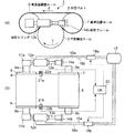
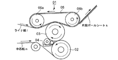
図6に図示されるように、加圧ベルト式シングルフェーサ01は、噛合い面が波形をした一対の段ロール02及び03間に中芯紙nを通して中芯紙nを波形に形成し、波形に形成された中芯紙nの段頂部に糊付装置04で糊付けした後、一方の段ロール(下流側段ロール)03とエンドレス状の加圧ベルト05との間に中芯紙nとライナ紙lとを重ね合わせて通過させ、この通過時に中芯紙nとライナ紙lが加圧接着されて、片面段ボール紙kが製造される。
As shown in FIG. 6, the pressure belt type
加圧ベルト05は通常弾性をもつ材質、例えば、テフロン(登録商標)でコーティングしたFRP材で製造される。加圧ベルト05は一対の平行に配置された加圧ロール06a及び06bに巻回されて走行される。そして、該加圧ロール間の距離を変えることにより、加圧ベルト05の張力を変え、それによって、加圧ロールの下流側段ロール03に対する加圧力を調整するようにしている。
The
加圧ベルト方式は、加圧ロール方式等と比べて、ベルトと段ロールとの接触範囲が長いため接触圧が小さく、また振動や騒音の発生が少なく品質の優れた段ボール紙が得られるなどの利点がある。 The pressure belt method has a longer contact range between the belt and the corrugated roll than the pressure roll method, etc., so that the contact pressure is small, and the generation of vibration and noise is low, resulting in an excellent quality corrugated paper. There are advantages.
加圧ベルトは、製作に際して幅方向両側部の周長を同一寸法に形成することが難しく、また長期の使用によって幅方向両側部の伸び量に差ができたり、一対の加圧ロールの平行度不良等の理由により、加圧ベルトの走行に伴い、一方の側が他方の側より先に進む不具合(先進)が発生する傾向にある。周長の短い側が先進し、先進する状態で捩れが発生し、長時間使用すると、破損するおそれがある。 When manufacturing a pressure belt, it is difficult to form the circumference of both sides in the width direction to the same dimension, and the elongation of the both sides in the width direction can be different due to long-term use, or the parallelism of a pair of pressure rolls For reasons such as defects, a problem (advanced) in which one side advances ahead of the other side with the traveling of the pressure belt tends to occur. The side with the shorter circumference is advanced, twisting occurs in the advanced state, and there is a risk of damage if used for a long time.
一般的なエンドレスベルトでは、該エンドレスベルトを巻回した加圧ロール間の間隔を調整するため加圧ロ−ルの両端部間に一対の加圧シリンダが架設されている。そして、前記不具合を解消するため、その先進状況を検出器により把握した後、先進する側の加圧シリンダの加圧力を増大し、先進する側の周長を他方より長くすることによって、一方の側のベルトの先進を相殺するようにしている。 In a typical endless belt, a pair of pressure cylinders is provided between both ends of the pressure roll in order to adjust the distance between the pressure rolls around which the endless belt is wound. And in order to eliminate the above-mentioned trouble, after grasping the advanced state by the detector, increasing the pressurizing force of the pressure cylinder on the advanced side and making the peripheral length of the advanced side longer than the other, The advance of the belt on the side is offset.
特許文献1(特開平11−105172号公報)には、加圧ベルトの幅方向両側部に金属製の被検出体を埋め込み、これら被検出体を金属センサで検出し、該検出結果に基づいて一対の加圧ロールの両端に架設された加圧シリンダのうち先進している側の加圧シリンダの油圧を高くして、該加圧シリンダを伸長させることで、加圧ベルトの両側部の周長差を解消するようにした手段が開示されている。 In Patent Document 1 (Japanese Patent Application Laid-Open No. 11-105172), metal detection objects are embedded on both sides of the pressure belt in the width direction, these detection objects are detected by a metal sensor, and based on the detection results. Of the pressure cylinders installed at both ends of the pair of pressure rolls, the pressure of the pressure cylinder on the advanced side is increased and the pressure cylinders are extended, so that the circumference of both sides of the pressure belt is increased. Means for eliminating the length difference is disclosed.
また、特許文献2(特開2001−121628号公報)には、加圧ベルトが巻回された一対の加圧ロールと、該一対の加圧ロールの両端間に架設され該一対の加圧ロールのうち一方の張力調製ロールの両端位置を夫々独立して移動させる一対の油圧シリンダと、該張力調整ロールの両端位置を検出する位置検出器とを設け、該一対の加圧ロールのうち他方の位置基準ロールから張力調製ロールの両端位置までの距離の差が所定範囲を超えると、該油圧シリンダを作動させてその差をなくすようにすることで、加圧ベルトの両側部の周長差を解消するようにした技術が手段されている。 Patent Document 2 (Japanese Patent Application Laid-Open No. 2001-121628) discloses a pair of pressure rolls around which a pressure belt is wound, and the pair of pressure rolls provided between both ends of the pair of pressure rolls. A pair of hydraulic cylinders that independently move both end positions of one of the tension adjusting rolls, and a position detector that detects both end positions of the tension adjusting roll, and the other of the pair of pressure rolls. When the difference in the distance from the position reference roll to the both ends of the tension adjusting roll exceeds a predetermined range, the difference between the circumferential lengths of both sides of the pressure belt is reduced by operating the hydraulic cylinder to eliminate the difference. Techniques to solve the problem have been taken.
特許文献1又は特許文献2に開示された手段では、加圧ベルトの幅方向両側部の周長差が、加圧ベルトの製作時に起こる場合、又は一対の加圧ロールの組み付け時の加圧ロールの平行度不良に起因して起こる場合、ベルトの先進している側に過張力が負荷される時間が長くなる傾向がある。そのため、先進している側が疲労破壊しやすくなる不具合がある。
In the means disclosed in
本発明は、かかる従来技術の課題に鑑み、加圧ベルトの幅方向両側部の周長差が、加圧ベルトの製作不良により発生したり、あるいは加圧ベルトが巻回される一対の加圧ロール組み付け時の加圧ロールの平行度不良等により発生した場合でも、加圧ベルトの片側にのみ過負荷をかけずに周長差を解消することを目的とする。
また、かかる操作を自動で行なうことにより、手動による周長差解消作業を不要にして、シングルフェーサの稼動を中止しないで済むようにすることを目的とする。
In the present invention, in view of the problems of the prior art, a difference in circumferential length between both sides in the width direction of the pressure belt is caused by a manufacturing failure of the pressure belt, or a pair of pressures around which the pressure belt is wound. An object is to eliminate the difference in circumferential length without overloading only one side of the pressure belt even when it occurs due to a parallelism failure of the pressure roll during roll assembly.
It is another object of the present invention to eliminate the need to manually eliminate the circumferential length difference and to avoid the operation of a single facer by automatically performing such operations.
前記目的を達成するため、第1の本発明のシングルフェーサの加圧ベルト制御方法は、
一対の加圧ロールに巻回されたエンドレス状の加圧ベルトの幅方向両側部の周長差を検知し、該周長差をなくすように制御するシングルフェーサの加圧ベルト制御方法において、
前記一対の加圧ロールの両端ロール軸間距離を調節する一対の加圧シリンダのうち加圧ベルトが先進する側の加圧シリンダに高加圧力を負荷して、加圧ロール軸間距離を広げる第1ステップと、
設定時間内で両加圧シリンダの高圧負荷時間を比較し、高圧負荷時間が長いほうの加圧シリンダを初期設定加圧力に戻すと共に、高圧負荷時間が短いほうの加圧シリンダの加圧力を予め設定された圧力値を減じた加圧力とする第2ステップと、からなり、
前記第2ステップを設定時間毎に繰り返すことにより、加圧ベルトの幅方向片側部に過負荷をかけずにベルト周長差をなくすようにしたものである。
In order to achieve the above object, a method for controlling a pressure belt of a single facer according to the first aspect of the present invention includes:
In the pressure control method of the single facer for detecting the circumferential length difference between both sides in the width direction of the endless pressure belt wound around the pair of pressure rolls, and controlling so as to eliminate the circumferential length difference,
A high pressure is applied to the pressure cylinder on the side where the pressure belt is advanced among the pair of pressure cylinders for adjusting the distance between the roll axes at both ends of the pair of pressure rolls, thereby widening the distance between the pressure roll axes. The first step;
The high pressure load times of both pressure cylinders are compared within the set time, the pressure cylinder with the longer high pressure load time is returned to the initial set pressure, and the pressure force of the pressure cylinder with the shorter high pressure load time is set in advance. A second step of applying a pressure obtained by subtracting the set pressure value,
By repeating the second step every set time, the belt circumferential length difference is eliminated without overloading one side in the width direction of the pressure belt.
第1の本発明方法では、稼動開始時には、一対の加圧シリンダに同等の初期設定加圧力を負荷させる。その後、加圧ベルトの幅方向両側部の周長差を検知し、周長差が発生している時は、加圧ベルトが先進する側の加圧シリンダに高加圧力を負荷して、周長を伸ばし、周長差を解消するようにする(第1ステップ)。このとき、両加圧シリンダに高加圧力を負荷した時間を記録しておく。 In the first method of the present invention, at the start of operation, an equivalent initial set pressure is applied to the pair of pressure cylinders. After that, the circumference difference of both sides in the width direction of the pressure belt is detected, and when the circumference difference has occurred, high pressure is applied to the pressure cylinder on the side where the pressure belt is advanced, Extend the length to eliminate the circumference difference (first step). At this time, the time during which high pressure is applied to both pressure cylinders is recorded.
そして、設定時間(例えば3〜5分)内で高圧負荷時間が長いほうの加圧シリンダを初期設定加圧力に戻すようにするため、加圧ベルトの先進した側に高圧が長時間負荷されることはない。同時に、高圧負荷時間が短いほうの加圧シリンダの加圧力を初期設定加圧力から予め設定された圧力値を減じた加圧力とするため、加圧ベルトの幅方向両側部で周長差を増大させないようにしている(第2ステップ)。 Then, in order to return the pressure cylinder having the longer high pressure load time within the set time (for example, 3 to 5 minutes) to the initial set pressure, a high pressure is applied to the advanced side of the pressure belt for a long time. There is nothing. At the same time, the circumferential pressure difference is increased on both sides of the pressure belt in the width direction, so that the pressure applied to the pressure cylinder with the shorter high-pressure load time is the pressure obtained by subtracting the preset pressure value from the initial set pressure. (2nd step).
この操作を設定時間毎に繰り返すことにより、加圧ベルトの幅方向片側部に過負荷をかけずに、周長差を解消させるようにする。これによって、加圧ベルトの走行性を安定させることができる。 By repeating this operation every set time, the circumferential length difference is eliminated without overloading one side in the width direction of the pressure belt. Thereby, the running performance of the pressure belt can be stabilized.
第1の本発明方法の前記第1ステップにおいて、設定時間内での高圧負荷時間の比が下限設定値を下回るか又は上限設定値を上回ったときに、高圧負荷時間が長いほうの加圧シリンダを初期設定加圧力に戻し、高圧負荷時間が短いほうの加圧シリンダの加圧力を予め設定された圧力値を減じた加圧力とするようにしてもよい。
このように、前記下限設定値及び上限設定値をもうけ、両加圧シリンダの高圧負荷時間の比が該下限設定値と上限設定値の間は許容範囲として、加圧シリンダの加圧力を変動させないようにすることで、制御に安定性をもたせることができる。
In the first step of the first method of the present invention, when the ratio of the high pressure load time within the set time falls below the lower limit set value or exceeds the upper limit set value, the pressure cylinder having the longer high pressure load time May be returned to the initial set pressure, and the pressure applied to the pressurizing cylinder having a shorter high-pressure load time may be set to a pressure obtained by subtracting a preset pressure value.
As described above, the lower limit set value and the upper limit set value are provided, and the pressure of the pressurizing cylinder is not changed while the ratio of the high pressure load times of the two pressurizing cylinders is within the allowable range between the lower limit set value and the upper limit set value. By doing so, stability can be given to control.
また、第2の本発明のシングルフェーサの加圧ベルト制御方法は、
一対の加圧ロールに巻回されたエンドレス状の加圧ベルトの幅方向両側部の周長差を検知し、該周長差をなくすように制御するシングルフェーサの加圧ベルト制御方法において、
加圧ベルトの幅方向両側部に加圧ベルトに対して進退するベルト周長調節ヘッドを備えたベルト周長調節装置を用意し、
加圧ベルトが先進する側のベルト周長調節ヘッドを伸ばして加圧ベルトの周長を伸ばす第1ステップと、
設定時間内で加圧ベルト伸長時間の長いほうのベルト周長調節ヘッドを設定ストローク分だけ伸ばすと共に、加圧ベルト伸長時間が短いほうのベルト周長調節ヘッドを加圧ベルトに負荷をかけない初期位置に戻す第2ステップ、とからなり、
前記第2ステップを設定時間毎に繰り返すことにより、加圧ベルトの幅方向片側部に過負荷をかけずにベルト周長差をなくすようにしたものである。
Further, the pressure control method for the single facer of the second aspect of the present invention is as follows:
In the pressure control method of the single facer for detecting the circumferential length difference between both sides in the width direction of the endless pressure belt wound around the pair of pressure rolls, and controlling so as to eliminate the circumferential length difference,
Prepare a belt circumference adjusting device with a belt circumference adjusting head that advances and retreats with respect to the pressure belt on both sides in the width direction of the pressure belt,
A first step of extending the circumference of the pressure belt by extending the belt circumference adjustment head on the side where the pressure belt is advanced;
Within the set time, the belt circumference adjustment head with the longer pressurization belt extension time is extended by the set stroke, and the belt circumference adjustment head with the shorter pressurization belt extension time is not applied to the pressure belt in the initial stage. The second step of returning to position,
By repeating the second step every set time, the belt circumferential length difference is eliminated without overloading one side in the width direction of the pressure belt.
第2の本発明方法では、稼動開始時には、周長調節ヘッドを加圧ベルトに負荷をかけない初期位置に位置させる。その後、加圧ベルトの幅方向両側部の周長差を検知し、周長差が発生している時は、加圧ベルトが先進する側の周長調節ヘッドを伸ばして加圧ベルトを押す。これによって、加圧ベルトの周長を伸ばし、周長差を解消するようにする(第1ステップ)。このとき、両周長調節ヘッドを伸ばした時間を記録しておく。 In the second method of the present invention, at the start of operation, the circumferential length adjusting head is positioned at an initial position where no load is applied to the pressure belt. Thereafter, a difference in circumferential length between both sides in the width direction of the pressure belt is detected. When the circumferential length difference occurs, the circumferential length adjustment head on the side where the pressure belt is advanced is extended and the pressure belt is pushed. As a result, the circumference of the pressure belt is extended to eliminate the circumference difference (first step). At this time, the time for extending both circumference adjusting heads is recorded.
そして、設定時間(例えば3〜5分)内で、両周長調節ヘッドによる先進のための加圧ベルト伸長時間が長いほうの周長調節ヘッドを設定ストローク分だけ伸ばすことにより、周長差をなくすようにする。同時に、高圧負荷時間が短いほうの加圧シリンダの加圧力を予め設定された圧力値を減じた加圧力とすることによって、加圧ベルトの幅方向両側部で周長差を増大させないようにする(第2ステップ)。 Then, within the set time (for example, 3 to 5 minutes), the circumference adjustment head with the longer pressure belt extension time for advancement by the both circumference adjustment heads is extended by the set stroke, so that the circumference difference is reduced. Try to lose it. At the same time, the pressure applied to the pressure cylinder with the shorter high-pressure load time is set to a pressure obtained by subtracting a preset pressure value so as not to increase the circumferential length difference on both sides in the width direction of the pressure belt. (Second step).
この操作を設定時間毎に繰り返すことにより、加圧ベルトの幅方向片側部に過負荷をかけずに、周長差を解消させるようにする。これによって、加圧ベルトの走行性を安定させることができる。 By repeating this operation every set time, the circumferential length difference is eliminated without overloading one side in the width direction of the pressure belt. Thereby, the running performance of the pressure belt can be stabilized.
第2の本発明方法の前記第2ステップにおいて、設定時間内での加圧ベルト伸長時間の比が下限設定値を下回るか又は上限設定値を上回ったときに、加圧ベルト伸長時間が長いほうのベルト周長調節ヘッドを設定ストローク分だけ伸長させると共に、加圧ベルト伸長時間が短いほうのベルト周長調節ヘッドを加圧ベルトに負荷をかけない初期位置に戻すようにしてもよい。 In the second step of the second method of the present invention, when the ratio of the pressure belt extension time within the set time is less than the lower limit set value or exceeds the upper limit set value, the pressure belt extension time is longer. The belt circumference adjusting head may be extended by a set stroke, and the belt circumference adjusting head having a shorter pressure belt extension time may be returned to the initial position where no load is applied to the pressure belt.
このように、前記下限設定値及び上限設定値をもうけ、周長調節ヘッドの設定ストローク伸長時間の比が該下限設定値と上限設定値の間では制御しないようにすることで、頻繁な制御をなくし、制御に安定性をもたせることができる。 In this way, the lower limit set value and the upper limit set value are provided so that the ratio of the set stroke extension time of the circumference adjustment head is not controlled between the lower limit set value and the upper limit set value, thereby enabling frequent control. The stability can be given to the control.
また、第1の本発明方法及び第2の本発明方法において、好ましくは、前記下限設定値を0.87とし、前記上限設定値を1.15とするとよい。実機運転上の知見から、該下限設定値を下回ったり、又は該上限設定値を上回ったりすると、加圧ベルトが破損するおそれが出てくるので、これら設定値を目安に制御を行なうとよい。 In the first method of the present invention and the second method of the present invention, preferably, the lower limit set value is 0.87 and the upper limit set value is 1.15. From the knowledge of actual machine operation, if the lower limit set value is exceeded, or if the upper limit set value is exceeded, the pressure belt may be damaged. Therefore, it is preferable to perform control based on these set values.
また、第1の本発明方法を実施するための第1の本発明のシングルフェーサの加圧ベルト制御装置は、
一対の加圧ロールに巻回されたエンドレス状の加圧ベルトの幅方向両側部の周長差を検知し、該周長差をなくすように制御するシングルフェーサの加圧ベルト制御装置において、
前記一対の加圧ロールの両端ロール軸間距離を調節する一対の加圧シリンダと、
加圧ベルトが先進する側の加圧シリンダに高加圧力を負荷して、加圧ロール軸間距離を広げる第1ステップと、設定時間内の両加圧シリンダの高圧負荷時間を比較し、高圧負荷時間が長いほうの加圧シリンダを初期設定加圧力に戻すと共に、高圧負荷時間が短いほうの加圧シリンダの加圧力を予め設定された圧力値を減じた加圧力とする第2ステップを行なう制御装置と、を備えたものである。
Further, the single facer pressure belt control device of the first aspect of the present invention for carrying out the first aspect of the present invention comprises:
In the pressure belt control device of a single facer that detects a circumferential length difference between both sides in the width direction of an endless pressure belt wound around a pair of pressure rolls and controls to eliminate the circumferential length difference,
A pair of pressure cylinders for adjusting the distance between the roll axes on both ends of the pair of pressure rolls;
Compare the first step to increase the distance between the pressure roll axes by applying high pressure to the pressure cylinder on the side where the pressure belt is advanced, and the high pressure load time of both pressure cylinders within the set time. A second step is performed in which the pressure cylinder having the longer load time is returned to the initial set pressure, and the pressure of the pressure cylinder having the shorter high pressure load time is set to a pressure obtained by subtracting a preset pressure value. And a control device.
前記構成により、設定時間毎に前記第2ステップを繰り返すことにより、加圧ベルトの幅方向片側部に過負荷をかけずに、加圧ベルトの幅方向両側部で周長差をなくすことができる。そのため、加圧ベルトの走行性を安定させることができる。また、前記制御装置により、加圧ベルトの周長差を解消する制御を自動化できるため、シングルフェーサの稼動を休止させる必要がなくなる。 With the above configuration, by repeating the second step every set time, it is possible to eliminate the circumferential length difference on both sides in the width direction of the pressure belt without overloading one side in the width direction of the pressure belt. . Therefore, the running performance of the pressure belt can be stabilized. In addition, since the control device can automate the control for eliminating the difference in circumference of the pressure belt, it is not necessary to stop the operation of the single facer.
また、第2の本発明方法を実施するための第2の本発明のシングルフェーサの加圧ベルト制御装置は、
一対の加圧ロールに巻回されたエンドレス状の加圧ベルトの幅方向両側部の周長差を検知し、該周長差をなくすように制御するシングルフェーサの加圧ベルト制御装置において、
加圧ベルトの幅方向両側部に配置され加圧ベルトに向かって進退することにより加圧ベルトの周長を調整するベルト周長調節ヘッドを備えた複数のベルト周長調節装置と、
加圧ベルトが先進する側のベルト周長調節ヘッドを伸ばして加圧ベルトの周長を伸ばす第1ステップと、設定時間内で加圧ベルト伸長時間の長いほうのベルト周長調節ヘッドを設定ストローク分だけ伸ばすと共に、加圧ベルト伸長時間が短いほうのベルト周長調節ヘッドを加圧ベルトに負荷をかけない初期位置に戻す第2ステップを行なう制御装置と、を備えたものである。
In addition, the single facer pressure belt control device of the second aspect of the invention for carrying out the method of the second aspect of the invention comprises:
In the pressure belt control device of a single facer that detects a circumferential length difference between both sides in the width direction of an endless pressure belt wound around a pair of pressure rolls and controls to eliminate the circumferential length difference,
A plurality of belt circumference adjusting devices including belt circumference adjusting heads arranged on both sides in the width direction of the pressure belt and adjusting the circumference of the pressure belt by moving back and forth toward the pressure belt;
The first step of extending the belt circumference adjustment head on the side where the pressure belt is advanced to extend the circumference of the pressure belt, and the set stroke of the belt circumference adjustment head with the longer pressure belt extension time within the set time And a control device that performs a second step of extending the belt circumferential length adjusting head having a shorter pressure belt extension time to an initial position where no load is applied to the pressure belt.
前記構成により、設定時間毎に前記第2ステップを繰り返すことにより、加圧ベルトの幅方向片側部に過負荷をかけずに、加圧ベルトの幅方向両側部で周長差をなくすことができる。従って、加圧ベルトの走行性を安定させることができる。また、前記制御装置により、加圧ベルトの周長差を解消する制御を自動化できるため、シングルフェーサの稼動を休止させる必要がなくなる。 With the above configuration, by repeating the second step every set time, it is possible to eliminate the circumferential length difference on both sides in the width direction of the pressure belt without overloading one side in the width direction of the pressure belt. . Therefore, the running performance of the pressure belt can be stabilized. In addition, since the control device can automate the control for eliminating the difference in circumference of the pressure belt, it is not necessary to stop the operation of the single facer.
第1の本発明装置又は第2の本発明装置において、加圧ベルトの幅方向中央部にベルト周長調節ヘッドを備えたベルト周長調節装置を設けて、加圧ベルト幅方向中央部の周長を幅方向両側部と独立して調節するように構成してもよい。加圧ベルトと段ロール間を通過するシート原紙の紙幅は種々あるため、シート原紙が加圧ベルト上を摺動する時間は、幅方向両側部より中央部のほうが多い。 In the first invention device or the second invention device, a belt circumference adjusting device having a belt circumference adjusting head is provided at the center in the width direction of the pressure belt, and the circumference of the center in the width direction of the pressure belt is provided. You may comprise so that length may be adjusted independently of the width direction both sides. Since there are various sheet widths of the sheet base paper passing between the pressure belt and the corrugated roll, the time during which the sheet base paper slides on the pressure belt is longer in the central portion than in both sides in the width direction.
そのため、シート原紙の貼合時に、加圧ベルトに接するシート原紙の摩擦力の影響で、加圧ベルトの中央部が両側部と比較して先進又は後進することがある。そのため、加圧ベルトの幅方向中央部に周長調節ヘッドを備えたベルト周長調整装置を設け、該周長調節ヘッドのストロークを幅方向両側部と独立して調整することにより、ベルト中央部の先進又は後進を相殺することができる。 For this reason, when the sheet base paper is bonded, the central portion of the pressure belt may be advanced or moved backward as compared with the both side portions due to the influence of the frictional force of the sheet base paper in contact with the pressure belt. Therefore, by providing a belt circumference adjusting device having a circumference adjusting head at the center in the width direction of the pressure belt, and adjusting the stroke of the circumference adjusting head independently from both sides in the width direction, Can cancel out advanced or reverse movements.
第1又は第2の本発明によれば、加圧ベルト製作時に幅方向両側部の周長差を生じた場合、又は一対の加圧ロールのシングルフェーサへの組み付け時に平行度不良が生じた場合等でも、加圧ベルトの片側部のみに過負荷をかけずに、ベルト幅方向両側部の周長差を解消して、走行性を安定させることができる。従って、加圧ベルトの一方の側の先進によって発生する捩れや、過張力の負荷による疲労破壊、さらには蛇行をなくすことができる。
また、制御を自動化できるため、ベルト周長差に応じて手動により加圧ロールの平行度を調製する等の作業が不要になり、シングルフェーサの稼動を休止させる必要がなくなる。
According to the first or second aspect of the present invention, when the pressure belt is produced, a difference in circumferential length between both sides in the width direction is produced, or when the pair of pressure rolls is assembled to the single facer, a parallelism defect occurs. Even in such a case, the traveling performance can be stabilized by eliminating the circumferential length difference on both sides in the belt width direction without overloading only one side of the pressure belt. Accordingly, it is possible to eliminate the twist caused by the advancement of one side of the pressure belt, the fatigue failure due to the over tension load, and the meandering.
Further, since the control can be automated, it is not necessary to manually adjust the parallelism of the pressure rolls according to the belt circumference difference, and it is not necessary to stop the operation of the single facer.
以下、本発明を図に示した実施形態を用いて詳細に説明する。但し、この実施形態に記載されている構成部品の寸法、材質、形状、その相対配置などは特に特定的な記載がない限り、この発明をそれのみに限定する趣旨ではない。 Hereinafter, the present invention will be described in detail with reference to embodiments shown in the drawings. However, the dimensions, materials, shapes, relative arrangements, and the like of the component parts described in this embodiment are not intended to limit the present invention to that only, unless otherwise specified.
(実施形態1)
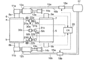
第1の本発明の一実施形態を図1〜図2に基づいて説明する。図1の(a)及び(b)は、シングルフェーサ1の一部を示す。図1において、一対の加圧ロールは周長差調整ロール6と基準位置ロール7とで構成されている。基準位置ロール7の両側ロール軸9a及び9bは図示しない固定軸受に回転可能にかつ平行移動しないように支持される。周長差調整ロール6の両端ロール軸8a又は8bは、夫々接続部11a又は11bを介して油圧シリンダ12a又は12bに接続されている。
なお、同一数字に異なるアルファベット文字を付して表示した複数の部材又は機器を数字のみで示すときは、これら部材又は機器に共通する記述である。
(Embodiment 1)
An embodiment of the first invention will be described with reference to FIGS. FIGS. 1A and 1B show a part of the
In addition, when the several member or apparatus displayed by attaching | subjecting a different alphabetic character to the same number is shown only with a number, it is a description common to these members or apparatuses.
油圧シリンダ12のピストンロッド13は、夫々固定フレーム14に接続されている。周長差調整ロール6及び基準位置ロール7にはエンドレス状の加圧ロール5が巻回されている。加圧ロール5は弾性を有する材質、例えばテフロン(登録商標)でコーティングをしたFRP材で製造されている。加圧ロール5は、周長差調整ロール6及び基準位置ロール7に巻回されて張力が付与されることで、下流側段ロール3を加圧する。
The piston rod 13 of the hydraulic cylinder 12 is connected to the fixed frame 14 respectively. An
下流側段ロール3の内部には飽和蒸気が導入されて、下流側段ロール3の外周面が加熱される。そして、段頂部に糊付けされた図示しない中芯紙とライナ紙とが重ね合わされた状態で加圧ロール5と下流側段ロール3間を通ることによって、加熱及び加圧されて貼り合わされる。
Saturated steam is introduced into the
油圧シリンダ12の左右油室には夫々作動油給排路15及び16が接続され、作動油給排路15、16の他端は作動油供給源17に接続されている。作動油給排路15a及び16aには電磁弁18aが介設され、作動油給排路15b及び16bには電磁弁18bが介設されている。制御装置20によって電磁弁18の開閉又は開度が制御されることによって、油圧シリンダ12の作動が制御され、周長調整ロール6の両ロール軸8a、8bに負荷される加圧力が制御される。
The hydraulic oil supply / discharge passages 15 and 16 are connected to the left and right oil chambers of the hydraulic cylinder 12, and the other ends of the hydraulic oil supply / discharge passages 15 and 16 are connected to the hydraulic
加圧ベルト5の幅方向両端の周方向同一位置に検出片(又は検出マーク)21a及び21bが埋設されている。そして、加圧ベルト5の幅方向両端に対峙させて、加圧ベルト5の周方向同一位置に検出片21を検出する非接触式の検出器22を配設している。検出器22は、透過式光電管等、従来公知の装置を用いる。
Detection pieces (or detection marks) 21 a and 21 b are embedded in the same position in the circumferential direction at both ends in the width direction of the
かかる構成の本実施形態において、制御装置20では、検出器22aで検出片21aを検知した時間と、検出器22bで検出片21bを検知した時間との時間差からベルト幅方向両側部のどちらか(a側又はb側)がどれだけ先進しているかを演算する。運転開始時には、制御装置20で電磁弁18を操作して、油圧シリンダ12に初期設定加圧力Po(例えば8MPa)を負荷しておく。
In the present embodiment having such a configuration, in the
運転開始後、検出器22a、22bで先進量を把握した後、制御装置20で先進している側の油圧シリンダに高加圧力(例えば1.0〜1.1MPa)を負荷させ、そのピストンロッドを延ばすことにより、先進している側のベルト周長を長くして、先進量を相殺する。例えば、加圧ベルト5の周長が3000mmのときに、両側部で30mmの周長差が生じたときに、先進側の油圧シリンダに前記高加圧力を負荷する。
After starting the operation, after detecting the advanced amount by the
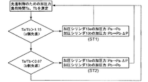
このとき、油圧シリンダ12a又は12bに高加圧力を負荷した時間Ta又はTbが制御装置20の内部で記録される。以後の制御装置20で行なわれる制御フローを図2に示す。図2において、ある設定時間(例えば3〜5分)内に、油圧シリンダ12a又は12bに先進制御のために高加圧力を負荷した時間Ta又はTbの比率を比較する。Ta/Tbが1.15を越えた場合は、油圧シリンダ12aの高圧負荷時間が油圧シリンダ12bの高圧負荷時間の1.15倍以上であるため、加圧ベルト5のa側への高圧負荷状態を緩和させる。
At this time, the time Ta or Tb when the high pressure is applied to the
シングルフェーサ1の運転上の知見から、Ta/Tb<0.87又は1.15<Ta/Tbになると、加圧ベルト5に捩れが発生し、蛇行や、過張力により疲労破壊のおそれがあることがわかっている。
From the operational knowledge of the
そのため、油圧シリンダ12aの加圧力を初期設定加圧力Poに戻すと共に、油圧シリンダ12bの加圧力を初期設定加圧力Poから圧力ΔP(例えば40KPa)だけ減じる。上記操作後もTa/Tb>1.15となる場合は、油圧シリンダ12bの加圧力PbをΔP刻みで減少させ、Ta/Tb≦1.15となるまで加圧力を調整する(ステップ1)。
Therefore, the applied pressure of the
Ta/Tb<0.87のときは、油圧シリンダ12bの高圧負荷時間が油圧シリンダ12aの1.15倍以上であるため、加圧ベルト5のb側への高圧負荷状態を緩和させる。即ち、油圧シリンダ12aを初期設定加圧力Poから圧力ΔPだけ減じると共に、油圧シリンダ12bを初期設定加圧力Poに戻す。前記操作後もTa/Tb<0.87となるときは、油圧シリンダ12aの加圧力PaをΔP刻みで減少させ、0.87≦Ta/Tbとなるまで油圧シリンダ12aの加圧力Paを調整する(ステップ2)。
When Ta / Tb <0.87, since the high pressure load time of the
前記ステップ1及びステップ2を繰り返して、0.87≦Ta/Tb≦1.15の範囲になるまで、油圧シリンダ12a及び12bの加圧力Pa、Pbを制御装置20で自動的に制御する。
本実施形態によれば、加圧ベルト製作時の幅方向両側部の周長差や加圧ベルト組立時の平行度不良等による片側先進傾向が発生した場合でも、制御装置20で油圧シリンダ12a又は12bの加圧力を自動的に調整して、片側先進状態を解消できるので、加圧ベルト5の走行性を安定させることができる。また、これを加圧ベルト5の片側に過負荷をかけずにできるので、加圧ベルト5に捩れや破損、あるいは蛇行が発生するおそれがない。
According to the present embodiment, even when a one-sided advanced tendency occurs due to a difference in circumferential length between both sides in the width direction when the pressure belt is manufactured, a parallelism defect when the pressure belt is assembled, or the like, the
また、Ta/Tb<0.87又は1.15<Ta/Tbのときは、加圧ベルト5の過張力が負荷される時間の長い側が破損するおそれがあるが、本実施形態では、0.87≦Ta/Tb≦1.15の範囲を維持するように自動制御しているので、加圧ベルト5の張力負荷が均一になり、破損のおそれがない。また、前記範囲内のときは、制御しないようにしたので、頻繁な制御をなくして、制御の安定性を維持することができる。
Further, when Ta / Tb <0.87 or 1.15 <Ta / Tb, there is a risk that the side where the over tension of the
また、油圧シリンダ12a又は12bの加圧力切替え時間は、制御装置20に記録されたデータから演算でき、そのため、余分な計測器や機械部品を追設する必要がない。従って、ソフトウェアのみの構築ですみ、低コストで安定した蛇行制御を可能とする。
さらに、自動制御のため、ベルト周長差に応じて加圧ロールの平行度を調整する作業が不要となるので、シングルフェーサ1の稼動を休止させる必要がない。
Further, the pressure switching time of the
Furthermore, because of the automatic control, there is no need to adjust the parallelism of the pressure rolls according to the belt circumferential length difference, so there is no need to suspend the operation of the
(実施形態2)
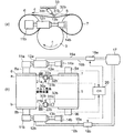
次に、第2の本発明の第1実施形態を図3及び図4に基づいて説明する。図3において、図1と同一の部材又は機器には同一符号を付しており、これら部材又は機器の説明は重複するので省略する。本実施形態は、図1に示す実施形態1の構成に加えて、ベルト周長調整装置30a及び30bを設けたものである。
(Embodiment 2)
Next, a first embodiment of the second invention will be described with reference to FIGS. In FIG. 3, the same members or devices as those in FIG. 1 are denoted by the same reference numerals, and descriptions of these members or devices are omitted because they are duplicated. In the present embodiment, belt circumferential
ベルト周長調節装置30a及び30bは、油圧シリンダからなり、一端が加圧ベルト5の上方に設置された固定フレーム33に接続されている。そして、作動油により伸縮可能なピストンロッド31a、31bを備え、該ピストンロッドの先端にベルト周長調節ロール32a、32bが回動可能に装着されている。ベルト周長調節ロール32は、加圧ベルト5の上方で加圧ベルト5の幅方向両側部に位置し、加圧ベルト上面に向けて伸縮可能に配置されている。その他の構成は実施形態1と同一である。
The belt circumferential
なお、ベルト周長調節ロール32の図示しない左右油室には、油圧シリンダ12と同様に、作動油給排路が接続され、作動油給排路には制御装置20によって開度が制御される電磁弁が介設され、かつ作動油給排路の他端は作動油供給源17に接続されているが、これらの図示は省略する。
In the same way as the hydraulic cylinder 12, a hydraulic oil supply / discharge passage is connected to the left and right oil chambers (not shown) of the belt circumferential length adjusting roll 32, and the opening degree is controlled by the
次に、本実施形態の制御方法を図4に基づいて説明する。まず、稼動開始時には、油圧シリンダ12a及び12bに初期設定加圧力Po(例えば8MPa)が負荷され、加圧ベルト5に初期設定張力が付与される。これによって、加圧ベルト5と下流側段ロール3間を通るシート原紙に初期設定圧力を付与する。
Next, the control method of this embodiment is demonstrated based on FIG. First, at the start of operation, an initial set pressure Po (for example, 8 MPa) is applied to the
本実施形態においては、稼動開始時に油圧シリンダ12a又は12bに初期設定加圧力Poを負荷して、加圧ベルト5の初期張力を設定し、その後、専ら加圧ベルト5の張力調整のみを行ない、加圧ベルト5の先進制御には関与しない。
また、稼動開始時、ベルト周長調節ロール32a及び32bは、加圧ベルト5に接するが加圧ベルト5を伸長させない初期ストローク位置Loに位置される。
In this embodiment, the initial set pressure Po is applied to the
Further, at the start of operation, the belt circumferential length adjusting rolls 32 a and 32 b are positioned at an initial stroke position Lo that contacts the
次に、検出器22で検出片21を検出して、加圧ベルト5の片側(a側又はb側)の先進量を把握する。そして、加圧ベルト5の先進している側のベルト周長調節装置のベルト周長調節ロールを伸長させて、ベルト周長を伸ばし、先進を相殺させる。このとき、ベルト周長調節ロール32a又は32bのストロークを伸ばした時間Ta又はTbが制御装置20内で記録され、演算処理される。以後の制御フローを図4に示す。
Next, the detection piece 21 is detected by the detector 22 to grasp the advanced amount on one side (a side or b side) of the
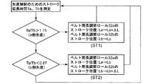
図4において、設定時間(例えば3〜5分)内で、ベルト周長調節ロール32a又は32bのベルト周長調節ロール32a又は32bが先進制御のために、ストロークを伸ばした時間Ta、Tbの比率を比較する。Ta/Tb>1.15の場合は、a側が先進傾向であるため、a側の先進傾向を緩和する操作を行なう。即ち、ベルト周長調節ロール32aのストローク位置を初期ストローク位置LoからΔLだけ伸ばした位置として、加圧ベルト5のa側の周長を伸ばす。一方、ベルト周長調節ロール32bのストローク位置は初期ストローク位置Loのままとする。
In FIG. 4, the ratio of the times Ta and Tb at which the belt
前記操作後のTa/Tb>1.15となる場合は、制御装置20によって、ベルト周長調節ロール32aのストローク位置をΔL刻みで伸ばし、Ta/Tb≦1.15となるまで、ベルト周長調節ロール32aのストローク位置を調整する(ステップ1)。
Ta/Tb<0.87の場合は、b側が先進傾向であるため、この傾向を緩和するため、ベルト周長調節ロール32bのストローク位置を初期ストローク位置LoからLo+ΔLに変更する。一方、ベルト周長調節ロール32aのストローク位置を初期ストローク位置Loに復帰させる。
When Ta / Tb> 1.15 after the above operation is satisfied, the
In the case of Ta / Tb <0.87, the b side has an advanced tendency. Therefore, in order to alleviate this tendency, the stroke position of the belt circumferential
前記操作後もTa/Tb<0.87となる場合は、ベルト周長調節ロール32bのストローク位置をΔL刻みで伸ばし、Ta/Tb≧0.87になるまで、ベルト周長調節ロール32bのストローク位置を調整する。前記ステップ1及びステップ2を繰り返して、0.87≦Ta/Tb≦1.15の範囲となるまでベルト周長調節ロール32a及び32bのストローク位置を、制御装置20によって自動的に制御する。
If Ta / Tb <0.87 even after the above operation, the stroke position of the belt circumferential
本実施形態によれば、加圧ベルト製作時に幅方向両側部の周長差が発生したり、加圧ベルト組立時の平行度不良等による片側先進傾向が発生した場合でも、油圧シリンダ12a又は12bの加圧力を自動的に調整して、加圧ベルト5の片側に過負荷をかけずに、片側先進状態を解消できる。これによって、走行性を安定させることができる。
その他、前記実施形態1と同様の作用効果を得ることができる。
According to this embodiment, even when a circumferential length difference occurs in both sides in the width direction when the pressure belt is manufactured, or when one-sided advanced tendency occurs due to poor parallelism when the pressure belt is assembled, the
In addition, the same effects as those of the first embodiment can be obtained.
(実施形態3)
次に、第2の本発明の第2実施形態を図5に基づいて説明する。図5において、本実施形態は、図3に示す前記実施形態2の構成に、さらにベルト周長調節装置30cを加圧ベルト5の上面中央部に配設したものである。ベルト周長調節装置30cは、ベルト周長調節装置30a、30bと同様に、伸縮可能なピストンロッド31c及びピストンロッド31cの先端に装着されたベルト周長調節ロール32cを備えている。その他の構成は、前記実施形態2と同一である。
(Embodiment 3)
Next, a second embodiment of the second invention will be described with reference to FIG. In FIG. 5, the present embodiment is such that a belt circumferential
本実施形態での制御フローは実施形態2と同一である。加圧ベルト5と下流側段ロール3間に中芯紙nとライナ紙lを挟んで貼合し、片面段ボール紙kを製造する際に、加圧ベルト5と下流側段ロール3間を通過するシート原紙の紙幅は種々あるため、シート原紙が加圧ベルト上を摺動する時間は、幅方向両側部より中央部のほうが多い。そのため、加圧ベルト5に接するこれらシート原紙の摩擦力の影響で加圧ベルト5の中央部が両側部と比べて先進又は後進することがある。
The control flow in this embodiment is the same as that in the second embodiment. Passing between the
本実施形態では、ベルト周長調節装置30cのベルト周長調節ロール32cのストロークを制御することにより、ベルト中央部の先進又は後進を相殺することができる。
なお、ベルト周長調節装置30cの操作は、制御装置20で制御するのではなく、オペレータが目視でベルト中央部の状態を見て、手動操作する。
In the present embodiment, by controlling the stroke of the belt
The operation of the belt circumferential
本実施形態によれば、前記実施形態2の作用効果に加えて、シート原紙の摩擦力の影響で加圧ベルト5の中央部が両側部と比べて先進又は後進する場合でも、ベルト周長調節ロール32cを伸縮させることにより、中央部の先進又は後進をなくして、加圧ベルト5の捩れや変形、蛇行等を防止することができる。
According to the present embodiment, in addition to the effects of the second embodiment, even when the central portion of the
なお、本実施形態では、実施形態2の構成にベルト周長調節装置30cを追設したものであったが、代わりに実施形態1の構成にベルト周長調節装置30cを追設するようにしてもよい。
In this embodiment, the belt circumferential
本発明によれば、片面段ボール紙を製造するシングルフェーサにおいて、加圧ベルトの片側先進をなくして、加圧ベルトの捩れや変形、あるいは破損、蛇行のおそれを解消できる自動化された手段を実現することができる。 According to the present invention, in a single facer for producing single-sided corrugated paper, an automated means that eliminates the risk of twisting, deformation, breakage, or meandering of the pressure belt by eliminating one-sided advancement of the pressure belt is realized. can do.
1 シングルフェーサ
3 下流側段ロール
5 加圧ベルト
6 周長差調整ロール
7 基準位置ロール
8a、8b、9a、9b ロール軸
12a、12b 油圧シリンダ(加圧シリンダ)
20 制御装置
21a、21b 検出片
22a、22b 検出器
30a、30b、30c ベルト周長調節装置
32a、32b、32c ベルト周長調節ロール
a、b 加圧ベルト5の幅方向両側部
Lo ベルト周長調節ロールの初期ストローク位置
Pa 加圧シリンダ12aの加圧力
Pb 加圧シリンダ12bの加圧力
Po 加圧シリンダ初期設定加圧力
DESCRIPTION OF
20
Claims (8)
前記一対の加圧ロールの両端ロール軸間距離を調節する一対の加圧シリンダのうち加圧ベルトが先進する側の加圧シリンダに高加圧力を負荷して、加圧ロール軸間距離を広げる第1ステップと、
設定時間内で両加圧シリンダの高圧負荷時間を比較し、高圧負荷時間が長いほうの加圧シリンダを初期設定加圧力に戻すと共に、高圧負荷時間が短いほうの加圧シリンダの加圧力を予め設定された圧力値を減じた加圧力とする第2ステップと、からなり、
前記第2ステップを設定時間毎に繰り返すことにより、加圧ベルトの幅方向片側部に過負荷をかけずにベルト周長差をなくすようにしたことを特徴とするシングルフェーサの加圧ベルト制御方法。 In the pressure control method of the single facer for detecting the circumferential length difference between both sides in the width direction of the endless pressure belt wound around the pair of pressure rolls, and controlling so as to eliminate the circumferential length difference,
A high pressure is applied to the pressure cylinder on the side where the pressure belt is advanced among the pair of pressure cylinders for adjusting the distance between the roll axes at both ends of the pair of pressure rolls, thereby widening the distance between the pressure roll axes. The first step;
The high pressure load times of both pressure cylinders are compared within the set time, the pressure cylinder with the longer high pressure load time is returned to the initial set pressure, and the pressure force of the pressure cylinder with the shorter high pressure load time is set in advance. A second step of applying a pressure obtained by subtracting the set pressure value,
The single facer pressure belt control is characterized by eliminating the belt circumference difference without overloading one side of the pressure belt in the width direction by repeating the second step every set time. Method.
加圧ベルトの幅方向両側部に加圧ベルトに対して進退するベルト周長調節ヘッドを備えたベルト周長調節装置を用意し、
加圧ベルトが先進する側のベルト周長調節ヘッドを伸ばして加圧ベルトの周長を伸ばす第1ステップと、
設定時間内で加圧ベルト伸長時間の長いほうのベルト周長調節ヘッドを設定ストローク分だけ伸ばすと共に、加圧ベルト伸長時間が短いほうのベルト周長調節ヘッドを加圧ベルトに負荷をかけない初期位置に戻す第2ステップ、とからなり、
前記第2ステップを設定時間毎に繰り返すことにより、加圧ベルトの幅方向片側部に過負荷をかけずにベルト周長差をなくすようにしたことを特徴とするシングルフェーサの加圧ベルト制御方法。 In the pressure control method of the single facer for detecting the circumferential length difference between both sides in the width direction of the endless pressure belt wound around the pair of pressure rolls, and controlling so as to eliminate the circumferential length difference,
Prepare a belt circumference adjusting device with a belt circumference adjusting head that advances and retreats with respect to the pressure belt on both sides in the width direction of the pressure belt,
A first step of extending the circumference of the pressure belt by extending the belt circumference adjustment head on the side where the pressure belt is advanced;
Within the set time, the belt circumference adjustment head with the longer pressurization belt extension time is extended by the set stroke, and the belt circumference adjustment head with the shorter pressurization belt extension time is not applied to the pressure belt in the initial stage. The second step of returning to position,
The single facer pressure belt control is characterized by eliminating the belt circumference difference without overloading one side of the pressure belt in the width direction by repeating the second step every set time. Method.
前記一対の加圧ロールの両端ロール軸間距離を調節する一対の加圧シリンダと、
加圧ベルトが先進する側の加圧シリンダに高加圧力を負荷して、加圧ロール軸間距離を広げる第1ステップと、設定時間内の両加圧シリンダの高圧負荷時間を比較し、高圧負荷時間が長いほうの加圧シリンダを初期設定加圧力に戻すと共に、高圧負荷時間が短いほうの加圧シリンダの加圧力を予め設定された圧力値を減じた加圧力とする第2ステップを行なう制御装置と、を備えたことを特徴とするシングルフェーサの加圧ベルト制御装置。 In the pressure belt control device of a single facer that detects a circumferential length difference between both sides in the width direction of an endless pressure belt wound around a pair of pressure rolls and controls to eliminate the circumferential length difference,
A pair of pressure cylinders for adjusting the distance between the roll axes on both ends of the pair of pressure rolls;
Compare the first step to increase the distance between the pressure roll axes by applying high pressure to the pressure cylinder on the side where the pressure belt is advanced, and the high pressure load time of both pressure cylinders within the set time. A second step is performed in which the pressure cylinder having the longer load time is returned to the initial set pressure, and the pressure of the pressure cylinder having the shorter high pressure load time is set to a pressure obtained by subtracting a preset pressure value. A single-facer pressurizing belt control device.
加圧ベルトの幅方向両側部に配置され加圧ベルトに向かって進退することにより加圧ベルトの周長を調整するベルト周長調節ヘッドを備えた複数のベルト周長調節装置と、
加圧ベルトが先進する側のベルト周長調節ヘッドを伸ばして加圧ベルトの周長を伸ばす第1ステップと、設定時間内で加圧ベルト伸長時間の長いほうのベルト周長調節ヘッドを設定ストローク分だけ伸ばすと共に、加圧ベルト伸長時間が短いほうのベルト周長調節ヘッドを加圧ベルトに負荷をかけない初期位置に戻す第2ステップを行なう制御装置と、を備えたことを特徴とするシングルフェーサの加圧ベルト制御装置。 In the pressure belt control device of a single facer that detects a circumferential length difference between both sides in the width direction of an endless pressure belt wound around a pair of pressure rolls and controls to eliminate the circumferential length difference,
A plurality of belt circumference adjusting devices including belt circumference adjusting heads arranged on both sides in the width direction of the pressure belt and adjusting the circumference of the pressure belt by moving back and forth toward the pressure belt;
The first step of extending the belt circumference adjustment head on the side where the pressure belt is advanced to extend the circumference of the pressure belt, and the set stroke of the belt circumference adjustment head with the longer pressure belt extension time within the set time And a controller for performing a second step of extending the belt circumference adjusting head having a shorter pressure belt extension time to an initial position where no load is applied to the pressure belt. Facer pressure belt control device.
A belt circumference adjustment device equipped with a belt circumference adjustment head is provided at the center of the pressure belt in the width direction, and the circumference of the center of the pressure belt in the width direction is adjusted independently of both sides in the width direction. The pressurizing belt control device for a single facer according to claim 6 or 7.
Priority Applications (1)
| Application Number | Priority Date | Filing Date | Title |
|---|---|---|---|
| JP2008043658A JP2009196330A (en) | 2008-02-25 | 2008-02-25 | Controlling method for pressurizing belt of single facer and apparatus for it |
Applications Claiming Priority (1)
| Application Number | Priority Date | Filing Date | Title |
|---|---|---|---|
| JP2008043658A JP2009196330A (en) | 2008-02-25 | 2008-02-25 | Controlling method for pressurizing belt of single facer and apparatus for it |
Publications (1)
| Publication Number | Publication Date |
|---|---|
| JP2009196330A true JP2009196330A (en) | 2009-09-03 |
Family
ID=41140382
Family Applications (1)
| Application Number | Title | Priority Date | Filing Date |
|---|---|---|---|
| JP2008043658A Withdrawn JP2009196330A (en) | 2008-02-25 | 2008-02-25 | Controlling method for pressurizing belt of single facer and apparatus for it |
Country Status (1)
| Country | Link |
|---|---|
| JP (1) | JP2009196330A (en) |
Cited By (1)
| Publication number | Priority date | Publication date | Assignee | Title |
|---|---|---|---|---|
| TWI718350B (en) * | 2017-01-23 | 2021-02-11 | 日商三菱重工機械系統股份有限公司 | Corrugated roller unit conveying device and replacement device and method of corrugated roller unit |
-
2008
- 2008-02-25 JP JP2008043658A patent/JP2009196330A/en not_active Withdrawn
Cited By (2)
| Publication number | Priority date | Publication date | Assignee | Title |
|---|---|---|---|---|
| TWI718350B (en) * | 2017-01-23 | 2021-02-11 | 日商三菱重工機械系統股份有限公司 | Corrugated roller unit conveying device and replacement device and method of corrugated roller unit |
| US11235549B2 (en) | 2017-01-23 | 2022-02-01 | Mitsubishi Heavy Industries Machinery Systems, Ltd. | Corrugating roll unit conveyance apparatus and apparatus and method for replacing corrugating roll unit |
Similar Documents
| Publication | Publication Date | Title |
|---|---|---|
| US3981758A (en) | Process control system for corrugators | |
| US9545769B2 (en) | Assembly for producing an endless single-face laminated web of corrugated cardboard | |
| JP5176347B2 (en) | Electrode plate pressing method and electrode plate pressing apparatus | |
| EP2476547A1 (en) | Corrugating machine for producing corrugated board and related method | |
| US9545779B2 (en) | Device for producing a web of corrugated cardboard that is laminated on at least one side | |
| US20140203059A1 (en) | Apparatus for controlling the nip force/pressure between two rotating cylinders | |
| JP4723459B2 (en) | Method and apparatus for preventing wrinkle generation during winding of rolled sheet | |
| RU2463165C2 (en) | Paper web processing device | |
| KR20140138043A (en) | Arrangement for producing a corrugated board web laminated on one side | |
| JP4924125B2 (en) | Steel sheet pile straightening method and steel sheet pile straightening device | |
| EP0878295A1 (en) | Improved single facer with small intermediate corrugating roll | |
| EP1491326B1 (en) | Device for joining sheets of cardboard to form corrugated cardboard | |
| JP2009196330A (en) | Controlling method for pressurizing belt of single facer and apparatus for it | |
| JP6143645B2 (en) | Double-sided corrugated sheet warpage preventing apparatus and method, and double-sided corrugated sheet manufacturing apparatus | |
| EP4204221A1 (en) | Plant and method for producing a corrugated board | |
| US5951817A (en) | Single facer having an auxiliary nip | |
| US9073282B2 (en) | Process for controlling the nip force/pressure between two rotating cylinders | |
| EP2792477B1 (en) | A corrugation device for sheets of paper material | |
| JP5509739B2 (en) | Thick plate shearing equipment, steel plate meander control method, and steel plate meander prevention method | |
| GB2281922A (en) | Apparatus for producing single-faced corrugated board sheets | |
| DE4215252A1 (en) | Welding together long strips of sheet metal - by displacing strips transversely to form butt or slightly overlapping joint and passing to welding machine | |
| JP3183223U (en) | Single-side corrugated sheet guide device | |
| JP4952854B1 (en) | Powder rolling apparatus and powder rolling method | |
| JP5707840B2 (en) | Method and apparatus for forming a pneumatic tire | |
| JP3192721U (en) | Single-side corrugated sheet guide device |
Legal Events
| Date | Code | Title | Description |
|---|---|---|---|
| A300 | Withdrawal of application because of no request for examination |
Free format text: JAPANESE INTERMEDIATE CODE: A300 Effective date: 20110510 |