JP2009195262A - Seat with headrest - Google Patents
Seat with headrest Download PDFInfo
- Publication number
- JP2009195262A JP2009195262A JP2008036846A JP2008036846A JP2009195262A JP 2009195262 A JP2009195262 A JP 2009195262A JP 2008036846 A JP2008036846 A JP 2008036846A JP 2008036846 A JP2008036846 A JP 2008036846A JP 2009195262 A JP2009195262 A JP 2009195262A
- Authority
- JP
- Japan
- Prior art keywords
- backrest
- headrest
- sheet
- chair
- cover
- Prior art date
- Legal status (The legal status is an assumption and is not a legal conclusion. Google has not performed a legal analysis and makes no representation as to the accuracy of the status listed.)
- Withdrawn
Links
Images


Abstract
Description
本発明は、着座した状態でヘッドレストの位置を自由に変えることのできるヘッドレスト付の椅子に関するものである。 The present invention relates to a chair with a headrest that can freely change the position of the headrest in a seated state.
被施療者の患部をマッサージするマッサージユニットを搭載したマッサージ椅子に、被施療者の頭部を保持するヘッドレスト(枕)を具えたものが提案されている(例えば、特許文献1参照)。
ヘッドレストは、使用者の体格、好み等に応じて、高さの調節を行なうことが望まれる。そこで、特許文献1では、面ファスナーによってヘッドレストを背凭れに貼着可能な構成とし、面ファスナーの着脱によりヘッドレストを所望の高さに取付けできるようにしている。
A massage chair equipped with a massage unit for massaging an affected area of a user has been proposed that includes a headrest (pillow) that holds the head of the user (see, for example, Patent Document 1).
The headrest is desired to be adjusted in height according to the user's physique and preferences. Therefore, in Patent Document 1, the headrest can be attached to the backrest with a hook-and-loop fastener, and the headrest can be attached to a desired height by attaching and detaching the hook-and-loop fastener.
ヘッドレストの高さ調整は、上記のように、使用者の個人差による体格等により一旦調整したとしても、同じ使用者であっても、使用中の姿勢の変化や、背凭れのリクライニング角度の変化等によって、使用者の頭部位置に対して、所望するヘッドレストの位置がずれてしまうことがある。また、予め設定したヘッドレスト高さの微調整を行ないたい場合もある。
このようなときに、面ファスナーによってヘッドレストを取り付けた構成であれば、使用者は、ヘッドレストの高さ調整を行なうために、一旦椅子から降りて立ち上がる必要があり、着座したままではヘッドレスト高さの調整することができない。
従って、着座状態(例えばマッサージ中)にヘッドレストの高さ調整や微調整を行なうことができなかった。
Headrest height adjustment as described above, even if it is adjusted once due to individual differences in user's physique, etc., even for the same user, changes in posture during use and changes in reclining angle of backrest The position of the desired headrest may shift with respect to the user's head position. In some cases, it may be desirable to finely adjust the preset headrest height.
In such a case, if the headrest is attached with a hook-and-loop fastener, the user needs to get out of the chair and stand up in order to adjust the height of the headrest. It cannot be adjusted.
Therefore, the height adjustment and fine adjustment of the headrest cannot be performed in the sitting state (for example, during massage).
本発明の目的は、着座状態でヘッドレストの高さ調整を容易に行なうことのできるヘッドレスト付椅子を提供することである。 The objective of this invention is providing the chair with a headrest which can perform the height adjustment of a headrest easily in a seating state.
上記課題を解決するために、本発明のヘッドレスト付椅子は、
使用者が凭れる背凭れ面を前面に有する背凭れと、
使用者の頭を保持するヘッドレストと、
を具えた椅子であって、
背凭れの頂部には、背凭れ面から背凭れの頂部を跨ぎ、背凭れの裏面に延びるベルト部材が前後にスライド可能に載置され、
ベルト部材は、背凭れ面側の端部にヘッドレストが取り付けられており、裏面側の端部にバランスウェイトが取り付けられている。
In order to solve the above problems, the chair with a headrest of the present invention is
A backrest having a backrest surface on which the user can lean;
A headrest that holds the user's head;
A chair with
On the top of the backrest, a belt member extending from the backrest surface to the top of the backrest and extending to the back surface of the backrest is slidably mounted back and forth,
The belt member has a headrest attached to an end portion on the backrest surface side and a balance weight attached to an end portion on the back surface side.
ヘッドレストは、ベルト部材を介してバランスウェイトに連繋されているから、ヘッドレストが背凭れ面側、バランスウェイトが裏面側、ベルト部材が背凭れ頂部を跨ぐように配置するだけで、ヘッドレストとバランスウェイトとの重量の釣り合いや、ベルト部材と背凭れ頂部との面接触による摩擦抵抗等により、ヘッドレストを背凭れ面に位置決めできる。
ヘッドレストは、使用者が手で押し上げたり、引き下げることにより、任意に位置決めすることができる。バランスウェイトにより重量の釣り合いがとれているから、ヘッドレストを位置調整するために大きな力は必要とならず、片手で軽く動かすことができる。
また、ヘッドレストは、背凭れに止着されていないから、使用者は椅子から立ち上がることなく、着座状態でヘッドレストの高さを調節することができる。このため、使用者の好みに応じた位置に微調整しやすい利点がある。
Since the headrest is linked to the balance weight via the belt member, the headrest and the balance weight can be placed just by placing the headrest over the backrest side, the balance weight over the backside, and the belt member over the backrest top. The headrest can be positioned on the backrest surface by the balance of the weight of the belt and the frictional resistance caused by the surface contact between the belt member and the backrest top portion.
The headrest can be arbitrarily positioned by being pushed up or pulled down by the user. Since the weight is balanced by the balance weight, a large force is not required to adjust the position of the headrest, and it can be moved lightly with one hand.
Moreover, since the headrest is not fixed to the backrest, the user can adjust the height of the headrest in the sitting state without standing up from the chair. For this reason, there exists an advantage which is easy to fine-tune to the position according to a user's liking.
[実施例1]
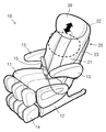
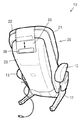
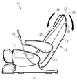
図1は、本発明の椅子(10)を斜め前方から見た斜視図、図2は、斜め後方から見た斜視図、図3は、左側面図である。
なお、本明細書において、使用者が椅子(10)に腰掛けた状態における胸側を「前」、背側を「後」、左手側を「左」、右手側を「右」と称する。また、本明細書では、本発明をマッサージ椅子に適用した例について説明するが、本発明は、マッサージ椅子に限定されず、背凭れを有する如何なる椅子や座椅子などにも適用することができる。
[Example 1]
FIG. 1 is a perspective view of the chair (10) of the present invention as viewed from diagonally forward, FIG. 2 is a perspective view as viewed from diagonally rear, and FIG. 3 is a left side view.
In the present specification, when the user is seated on the chair (10), the chest side is referred to as “front”, the back side as “rear”, the left hand side as “left”, and the right hand side as “right”. Moreover, although this specification demonstrates the example which applied this invention to the massage chair, this invention is not limited to a massage chair, It can apply to any chair, seat chair, etc. which have a backrest. .
図に示すように、椅子(10)は、使用者の腰掛ける座部(11)の後端に背凭れ(20)が連繋されている。座部(11)は、床面に載置されるベースフレーム(12)に取り付けられている。また、背凭れ(20)は、座部(11)に対してリクライニング可能に配備することができる。
図示の椅子(10)は、背凭れ(20)の左右に肘掛け(13)(13)を具え、背凭れ(20)の内部に肩、背及び腰用のマッサージユニット(図示せず)が昇降可能に配備されると共に、座部(11)の前端には、ふくらはぎ及び足先にマッサージを施す足用ユニット(14)が配備されている。背凭れ(20)のリクライニングやマッサージユニット等の制御は、肘掛け(13)に着脱可能に配備された操作器(15)により行なうことができる。
As shown in the figure, the chair (10) has a backrest (20) linked to the rear end of a seat (11) on which a user sits. The seat (11) is attached to a base frame (12) placed on the floor. Further, the backrest (20) can be disposed so as to be reclining with respect to the seat (11).
The illustrated chair (10) has armrests (13) and (13) on the left and right of the backrest (20), and a shoulder, back and waist massage unit (not shown) can be raised and lowered inside the backrest (20) And a foot unit (14) for applying massage to the calf and the tip of the foot at the front end of the seat (11). The reclining of the backrest (20), the control of the massage unit, and the like can be performed by an operating device (15) provided detachably on the armrest (13).
背凭れ(20)は、前面側に使用者が凭れる背凭れ面(21)が形成されている。本明細書では、背凭れ(20)の上端を背凭れ頂部(22)、背凭れ面(21)の逆側の面を裏面(23)と称する。 The backrest (20) has a backrest surface (21) on which the user can lean on the front side. In the present specification, the upper end of the backrest (20) is referred to as a backrest top portion (22), and the surface opposite to the backrest surface (21) is referred to as a back surface (23).
背凭れ(20)には、図1及び図3に示すように、使用者の頭部を保持するヘッドレスト(30)が上下に高さ調整可能に配備されている。
ヘッドレスト(30)は、内部にクッション材が収容され、外周をカバーにより包囲して構成された扁平体から構成することができ、使用者の頭部の座りをよくするために、頭部が当たる位置に凹みをもうけた構成とすることもできる。
As shown in FIGS. 1 and 3, the backrest (20) is provided with a headrest (30) for holding the user's head so that the height can be adjusted vertically.
The headrest (30) can be composed of a flat body that contains a cushion material inside and is surrounded by a cover, and the head hits the head to improve the sitting of the user's head. It can also be set as the structure which made the dent in the position.
ヘッドレスト(30)の裏面には、図2に示すように、ベルト部材(33)の一端が止着されており、ベルト部材(33)は、背凭れ頂部(22)を跨いで背凭れ裏面(23)に延びている。ベルト部材(33)は、背凭れ頂部(22)に対してスライド可能となっている。
ベルト部材(33)は、ヘッドレスト(30)の支持安定性を高めると共に、背凭れ頂部(22)との面接触による摩擦抵抗を高めてヘッドレスト(30)がずり落ちたり、ずり上がることがないようにするために、ひも状のものを使用するよりも、幅広の材料から構成することが望ましく、また、背凭れ(20)に上手く沿うようにするために可撓性の材料から構成することが望ましい。
As shown in FIG. 2, one end of a belt member (33) is fastened to the back surface of the headrest (30), and the belt member (33) straddles the backrest top portion (22). 23). The belt member (33) is slidable with respect to the backrest top portion (22).
The belt member (33) increases the support stability of the headrest (30) and increases the frictional resistance due to surface contact with the backrest (22) so that the headrest (30) does not slide down or slide up. Therefore, it is preferable to make it from a wide material rather than using a string-like material, and to make it from a flexible material so that it can follow the backrest (20) well. desirable.
ベルト部材(33)の他端には、図2及び図3に示すように、バランスウェイト(38)が取り付けられている。バランスウェイト(38)は、ヘッドレスト(30)とほぼ同じぐらいの重さの錘から構成することができる。 As shown in FIGS. 2 and 3, a balance weight (38) is attached to the other end of the belt member (33). The balance weight (38) can be composed of a weight that is approximately the same weight as the headrest (30).
ヘッドレスト(30)の背凭れ(20)への取付けは、ヘッドレスト(30)が背凭れ面(21)側、バランスウェイト(38)が背凭れ裏面(23)側に位置するように配置した状態で、ベルト部材(33)が背凭れ頂部(22)を跨ぐように載置すればよい。 Mount the headrest (30) on the backrest (20) with the headrest (30) positioned on the backrest (21) side and the balance weight (38) on the backrest (23). The belt member (33) may be placed so as to straddle the backrest (22).
然して、ヘッドレスト(30)は、バランスウェイト(38)との重量の釣り合い及びベルト部材(33)と背凭れ頂部(22)との摩擦抵抗によって、ずり落ちたり、ずり上がらないように位置決めされる。 However, the headrest (30) is positioned so as not to slide down or rise due to the weight balance with the balance weight (38) and the frictional resistance between the belt member (33) and the backrest top portion (22).
この状態で、着座した使用者が、ヘッドレスト(30)の位置を低くしたい場合には、片手又は両手でヘッドレスト(30)を引っ張るだけでよい。これにより、図1乃至図3に実線で示したヘッドレスト(30)、ベルト部材(33)及びバランスウェイト(38)が、図1乃至図3に点線で示すように移動して、ヘッドレスト(30)の高さ位置を下げることができる。ヘッドレスト(30)が所望の高さまで移動し、使用者がヘッドレスト(30)の引っ張りを止めると、ヘッドレスト(30)は、バランスウェイト(38)との重量の釣り合い及びベルト部材(33)と背凭れ頂部(22)との摩擦抵抗によって静止する。 In this state, when the seated user wants to lower the position of the headrest (30), it is only necessary to pull the headrest (30) with one or both hands. Accordingly, the headrest (30), the belt member (33), and the balance weight (38) shown by solid lines in FIGS. 1 to 3 are moved as shown by dotted lines in FIGS. Can be lowered. When the headrest (30) moves to the desired height and the user stops pulling the headrest (30), the headrest (30) balances with the balance weight (38) and backrest with the belt member (33). It stops by frictional resistance with the top (22).
逆に、使用者が、ヘッドレスト(30)の位置を高くしたい場合には、片手又は両手でヘッドレスト(30)を押し上げるだけでよい。これにより、図1乃至図3に点線で示したヘッドレスト(30)、ベルト部材(33)及びバランスウェイト(38)が、図1乃至図3に実線で示すように移動して、ヘッドレスト(30)の高さ位置を上げることができる。ヘッドレスト(30)が所望の高さまで移動し、使用者がヘッドレスト(30)の押し上げを止めると、ヘッドレスト(30)は、バランスウェイト(38)との重量の釣り合い及びベルト部材(33)と背凭れ頂部(22)との摩擦抵抗によって静止する。 On the contrary, when the user wants to raise the position of the headrest (30), it is only necessary to push up the headrest (30) with one hand or both hands. Accordingly, the headrest (30), the belt member (33), and the balance weight (38) indicated by dotted lines in FIGS. 1 to 3 are moved as indicated by solid lines in FIGS. The height position of can be raised. When the headrest (30) moves to the desired height and the user stops pushing up the headrest (30), the headrest (30) balances with the balance weight (38) and backrest with the belt member (33). It stops by frictional resistance with the top (22).
本発明のヘッドレスト付椅子(10)によれば、使用者は、着座した状態でヘッドレスト(30)の高さ調整を行なうことができ、また、バランスウェイト(38)との釣り合いにより、ヘッドレスト(30)の高さ調整に必要な力を小さくすることができる。
さらに、ヘッドレスト(30)の高さ位置は、任意に調整でき、微調整も容易に行なうことができる。
According to the headrest-equipped chair (10) of the present invention, the user can adjust the height of the headrest (30) while seated, and the headrest (30) can be adjusted by balancing with the balance weight (38). ) Can be reduced in force required for height adjustment.
Furthermore, the height position of the headrest (30) can be arbitrarily adjusted, and fine adjustment can be easily performed.
[実施例2]
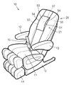
図4及び図5は、ベルト部材(33)を二重のシート(34)(35)により構成した実施例である。
ベルト部材(33)は、一端がヘッドレスト(30)に止着された第1シート(34)と第2シート(35)から構成している。なお、第1シート(34)と第2シート(35)の一端は、両方をヘッドレスト(30)に止着する必要はなく、何れか一方を止着して、他方を第1又は第2の何れかのシート(34)(35)に止着してもよい。また、第1シート(34)と第2シート(35)は、2枚のシートから作成することもできるし、1枚のシートを折り曲げて作成することもできる。
第1シート(34)は、第2シート(35)と背凭れ頂部(22)との間に介在するよう配備される。第1シート(34)は、第2シート(35)に比して幅狭の材料から構成することで、通常使用時に第1シート(34)や後述するベルト通し(25)が外部から視認されることはなく、外観上の見栄えを良好にすることができる。
第2シート(35)の自由端側には、実施例1と同様に、ヘッドレスト(30)とほぼ同じぐらいの重さの錘から構成されたバランスウェイト(38)が取り付けられている。バランスウェイト(38)は、第1シート(34)に取り付けることもできるし、第1シート(34)と第2シート(35)の両方に取り付けることもできる。
また、第1シート(34)と第2シート(35)の自由端側には、第1シート(34)と第2シート(35)とを互いに係止する面ファスナー等の係止手段(36)(36)が配備されている。
[Example 2]
4 and 5 show an embodiment in which the belt member (33) is constituted by double sheets (34) and (35).
The belt member (33) is composed of a first sheet (34) and a second sheet (35), one end of which is fixed to the headrest (30). Note that one end of the first sheet (34) and the second sheet (35) does not need to be fixed to the headrest (30), either one is fixed and the other is the first or second. It may be fixed to any one of the sheets (34) and (35). The first sheet (34) and the second sheet (35) can be created from two sheets, or can be created by bending one sheet.
The first seat (34) is arranged to be interposed between the second seat (35) and the backrest top portion (22). The first sheet (34) is made of a material that is narrower than the second sheet (35), so that the first sheet (34) and the belt loop (25) described later are visible from the outside during normal use. The appearance can be improved.
On the free end side of the second sheet (35), as in the first embodiment, a balance weight (38) composed of a weight that is almost the same weight as the headrest (30) is attached. The balance weight (38) can be attached to the first sheet (34), or can be attached to both the first sheet (34) and the second sheet (35).
Further, on the free end side of the first sheet (34) and the second sheet (35), locking means (36) such as a hook-and-loop fastener for locking the first sheet (34) and the second sheet (35) to each other. ) (36) is deployed.
背凭れ頂部(22)には、第1シート(34)が挿通するベルト通し(25)が設けられており、図4に示すように、第1シート(34)をベルト通し(25)に挿通させ、第1シート(34)と第2シート(35)を係止手段(36)によって係止することで、ヘッドレスト(30)は、背凭れ(20)に取り付けることができる。ヘッドレスト(30)を外したい場合には、係止手段(36)による係止を解き、第1シート(34)をベルト通し(25)から引き抜けばよい。 The backrest top (22) is provided with a belt loop (25) through which the first seat (34) is inserted. As shown in FIG. 4, the first seat (34) is inserted into the belt loop (25). The headrest (30) can be attached to the backrest (20) by locking the first sheet (34) and the second sheet (35) by the locking means (36). When it is desired to remove the headrest (30), the locking by the locking means (36) is released, and the first seat (34) is pulled out of the belt loop (25).
本実施例におけるヘッドレスト(30)の高さ調節は、実施例1と同様である。
本実施例では、ベルト部材(33)がベルト通し(25)に挿通されているため、ヘッドレスト(30)が横ずれしたり、背凭れ(20)から左右に脱落してしまうことはない。
また、第1シート(34)と第2シート(35)がベルト通し(25)を包囲するループを構成するため、ヘッドレスト(30)を引き下げ過ぎたときに、バランスウェイト(38)が背凭れ頂部(22)を乗り越えて、ヘッドレスト(30)が座部(11)側に脱落したり、ヘッドレスト(30)を押し上げ過ぎたときに、ヘッドレスト(30)が背凭れ頂部(22)を乗り越えて後方に落ちてしまうことを防止できる。
The height adjustment of the headrest (30) in the present embodiment is the same as that in the first embodiment.
In the present embodiment, since the belt member (33) is inserted through the belt loop (25), the headrest (30) does not slip laterally or fall off from the backrest (20) to the left or right.
In addition, since the first seat (34) and the second seat (35) form a loop surrounding the belt loop (25), the balance weight (38) is placed on the backrest when the headrest (30) is pulled down too much. If the headrest (30) falls off the seat (11) side after overcoming (22) or the headrest (30) is pushed up too much, the headrest (30) gets over the backrest (22) and moves backward. It can be prevented from falling.
さらに、本実施例の如き構成とすることにより、使用者がヘッドレスト(30)の使用を所望しない場合には、図5に示すように、ヘッドレスト(30)を後方に跳ね上げることもできる。 Further, by adopting the configuration as in the present embodiment, when the user does not want to use the headrest (30), the headrest (30) can be flipped up backward as shown in FIG.
なお、本実施例では、ベルト部材(33)を二重のシート(34)(35)で構成しているが、ヘッドレスト(30)の横ずれを防止するだけであれば、実施例1のベルト部材(33)をベルト通し(25)に挿通させる構成としてもよい。
また、本実施例と同様の効果を得るには、ベルト部材(33)が一重のシートであっても、ベルト部材(33)のバランスウェイト(38)の取り付けられた部分をベルト通し(25)よりも幅広として、ヘッドレスト(30)が最も低い位置まで移動させたときに抜止めとなるように構成し、その他の部分をベルト通し(25)よりも幅狭としてもよい。
In this embodiment, the belt member (33) is composed of double sheets (34) (35). However, the belt member of the first embodiment is only required to prevent the lateral displacement of the headrest (30). (33) may be inserted through the belt loop (25).
Further, in order to obtain the same effect as in the present embodiment, even if the belt member (33) is a single sheet, the portion of the belt member (33) where the balance weight (38) is attached is belt-passed (25). The width of the headrest (30) may be prevented from being removed when the headrest (30) is moved to the lowest position, and the other portions may be narrower than the belt loop (25).
[実施例3]
本実施例は、図6乃至図9に示すように、背凭れ(20)のカバー(50)の一部に、タック部(54)(55)を有する伸縮性の高いカバー(53)を用いたマッサージ椅子(10)に関するものである。なお、図中の符号について、上記実施例と同じ符号は同じ部材を意味しており、適宜説明を省略している。
[Example 3]
In this embodiment, as shown in FIGS. 6 to 9, a highly stretchable cover (53) having tack portions (54) and (55) is used as a part of the cover (50) of the backrest (20). The massage chair (10). In addition, about the code | symbol in a figure, the same code | symbol as the said Example means the same member, and it abbreviate | omits description suitably.
背凭れ(20)の内部にマッサージユニットを搭載し、該マッサージユニットの施療部(40)(40)を背凭れ面(21)から突出させてマッサージを施す公知のマッサージ椅子(10)では、使用者の肩近傍に効果の高いマッサージを施すことができるようにするために、例えば、特開2006−239400号公報に見られるように、肩近傍に位置する背凭れのカバーの一部に伸縮性の高い布を用い、さらに背凭れから施療部が抵抗なくを突出できるようにするために、施療部が当接する布の中央付近に縦及び/又は斜め方向(例えばY字型)にギャザー加工を施している。 The massage unit is mounted inside the backrest (20), and the treatment unit (40) (40) of the massage unit is protruded from the backrest surface (21), and the massager (10) used for massage is used. In order to be able to give a highly effective massage in the vicinity of a person's shoulder, for example, as seen in Japanese Patent Application Laid-Open No. 2006-239400, a part of the backrest cover located in the vicinity of the shoulder is stretchable. In order to allow the treatment part to protrude without resistance from the backrest, gather processing is performed in the vertical and / or diagonal direction (for example, Y-shaped) near the center of the cloth where the treatment part abuts. Has been given.
しかしながら、施療部が背凭れ面(21)から突出していない状態では、ギャザー近傍に布の弛みが生じてしまい、外見上の見栄えがよくないだけでなく、弛んだ布地が背凭れ内部のマッサージユニットに接触したり、挟み込まれてしまうことがあった。
そこで、本発明では、施療部(40)(40)が背凭れ面(21)から突出していない状態でも弛みが生じ難いマッサージ椅子を提供するようにした。
However, in the state where the treatment part does not protrude from the backrest surface (21), the looseness of the cloth occurs in the vicinity of the gathers, and not only the appearance does not look good, but also the loose cloth is a massage unit inside the backrest. May come into contact with or be pinched.
Therefore, in the present invention, a massage chair is provided that is less likely to sag even when the treatment portions (40), (40) do not protrude from the backrest surface (21).
図6乃至図9に示すように、背凭れ(20)の外周を覆う第1カバー(50)は、使用者の肩近傍に当たる位置に、施療部(40)(40)を大きく突出させるための開口(51)を有している。開口(51)は、第2カバー(53)により覆われている。 As shown in FIGS. 6 to 9, the first cover (50) covering the outer periphery of the backrest (20) is for projecting the treatment portions (40), (40) to a position where it is in the vicinity of the user's shoulder. It has an opening (51). The opening (51) is covered with a second cover (53).
第2カバー(53)は、第1カバー(50)よりも伸縮性の高い布等の材料を用いることが望ましい。
第2カバー(53)の上下端は、第1カバー(50)の開口(51)の縁に縫製、接着、溶着等により止着される。第2カバー(53)の左右端には、1又は複数回の折り返しが形成されたタック部(54)(55)を有しており、折り返し端(56)(56)が、第1カバー(50)の開口(51)の縁に縫製、接着、溶着等により止着されている(図8及び図9参照)。
The second cover (53) is preferably made of a material such as a cloth having higher stretchability than the first cover (50).
The upper and lower ends of the second cover (53) are fixed to the edge of the opening (51) of the first cover (50) by sewing, bonding, welding or the like. The left and right ends of the second cover (53) have tack portions (54) and (55) formed with one or more turns, and the turn-back ends (56) and (56) are connected to the first cover ( 50) is fixed to the edge of the opening (51) by sewing, bonding, welding or the like (see FIGS. 8 and 9).
第2カバー(53)の左右に蛇腹状のタック部(54)(55)を設けたことで、図8に示すように、施療部(40)(40)が突出していないときには、蛇腹を縮めた状態となり、開口(51)とほぼ同じ面内に後退する。一方、施療部(40)(40)が突出した場合には、図9に示すように、第2カバー(53)は、施療部(40)(40)に押し出されて、タック部(54)(55)が蛇腹状に伸び、開口(51)から飛び出す。再度、施療部(40)(40)が後退すると、タック部(54)(55)が図8に示す状態に復帰する。 By providing bellows-like tack portions (54) and (55) on the left and right sides of the second cover (53), as shown in FIG. 8, when the treatment portions (40) and (40) do not protrude, the bellows is shrunk. It will be in the state and it will recede in the surface substantially the same as opening (51). On the other hand, when the treatment portions (40) and (40) protrude, the second cover (53) is pushed out by the treatment portions (40) and (40) as shown in FIG. (55) extends in a bellows shape and jumps out of the opening (51). When the treatment sections (40) and (40) are moved back again, the tack sections (54) and (55) are restored to the state shown in FIG.
上記のように、第2カバー(53)にタック部(54)(55)を設けたことで、第2カバー(53)の弛みを阻止することができ、外観上の見栄えを良好にすることができ、また、第2カバー(53)とマッサージユニットの接触等も防止できる。 As described above, the second cover (53) is provided with the tack portion (54) (55), so that the second cover (53) can be prevented from slacking and the appearance is improved. In addition, contact between the second cover (53) and the massage unit can be prevented.
なお、タック部(54)(55)の蛇腹状の伸縮性をより高めるために、図8及び図9に示すように、タック部(54)(55)と平行に縫製等を施すことによりステッチ部(57)(57)を設けてもよい。 In order to further enhance the bellows-like stretchability of the tack portions (54) and (55), as shown in FIGS. 8 and 9, stitching is performed by performing sewing or the like in parallel with the tack portions (54) and (55). Units (57) and (57) may be provided.
また、第2カバー(53)と施療部(40)(40)との摩擦接触により、第2カバー(53)が摩耗してしまうことを防止するために、第2カバー(53)と施療部(40)(40)との間に、第2カバー(53)に対して低摩耗性の材料からなる第3カバー(59)を配置するようにしてもよい。 Further, in order to prevent the second cover (53) from being worn by frictional contact between the second cover (53) and the treatment portions (40) and (40), the second cover (53) and the treatment portion are prevented. (40) A third cover (59) made of a low-abrasion material may be disposed between the second cover (53) and (40).
本発明は、着座状態でヘッドレストの高さ調整を容易に行なうことのできるヘッドレスト付椅子として有用である。 The present invention is useful as a chair with a headrest that can easily adjust the height of the headrest in a sitting state.
(10) 椅子
(11) 座部
(20) 背凭れ
(21) 背凭れ面
(22) 背凭れ頂部
(23) 背凭れ裏面
(25) ベルト通し
(30) ヘッドレスト
(33) ベルト部材
(38) バランスウェイト
(10) Chair
(11) Seat
(20) Backrest
(21) Backrest
(22) Backrest top
(23) Backside back
(25) Belt loop
(30) Headrest
(33) Belt member
(38) Balance weight
Claims (7)
使用者の頭を保持するヘッドレストと、
を具えた椅子であって、
背凭れの頂部には、背凭れ面から背凭れの頂部を跨ぎ、背凭れの裏面に延びるベルト部材が前後にスライド可能に載置され、
ベルト部材は、背凭れ面側の端部にヘッドレストが取り付けられており、裏面側の端部にバランスウェイトが取り付けられていることを特徴とするヘッドレスト付椅子。 A backrest having a backrest surface on which the user can lean;
A headrest that holds the user's head;
A chair with
On the top of the backrest, a belt member extending from the backrest surface to the top of the backrest and extending to the back surface of the backrest is slidably mounted back and forth,
A headrest-equipped chair, wherein a headrest is attached to an end portion on a backrest side of a belt member, and a balance weight is attached to an end portion on the backside side.
該背凭れの内部に配備され、被施療者の患部をマッサージする施療部が背凭れ内部から前方に向けて突出したマッサージユニットと、
背凭れの外周を覆い、背凭れ面に施療部が突出する開口の形成された第1カバーと、
第1カバーの開口を覆い、周縁が第1カバーの開口縁に止着された第2カバーと、
を具えたマッサージ椅子において、
第2カバーは、左右端に折り返された蛇腹状のタック部を有し、折り返し端が第1カバーの開口縁に止着されていることを特徴とするマッサージ椅子。 A backrest having a backrest surface on which the user can lean;
A massage unit that is deployed inside the backrest, and a treatment unit that massages the affected area of the user protrudes forward from the backrest; and
A first cover that covers an outer periphery of the backrest and has an opening in which the treatment portion projects on the backrest surface;
A second cover that covers the opening of the first cover and whose periphery is fixed to the opening edge of the first cover;
In the massage chair with
The second cover has a bellows-like tack portion folded back at the left and right ends, and the folded end is fixed to the opening edge of the first cover.
Priority Applications (2)
| Application Number | Priority Date | Filing Date | Title |
|---|---|---|---|
| JP2008036846A JP2009195262A (en) | 2008-02-19 | 2008-02-19 | Seat with headrest |
| CNA2008101833981A CN101513309A (en) | 2008-02-19 | 2008-12-08 | Chair with pillow |
Applications Claiming Priority (1)
| Application Number | Priority Date | Filing Date | Title |
|---|---|---|---|
| JP2008036846A JP2009195262A (en) | 2008-02-19 | 2008-02-19 | Seat with headrest |
Publications (2)
| Publication Number | Publication Date |
|---|---|
| JP2009195262A true JP2009195262A (en) | 2009-09-03 |
| JP2009195262A5 JP2009195262A5 (en) | 2010-07-01 |
Family
ID=41038051
Family Applications (1)
| Application Number | Title | Priority Date | Filing Date |
|---|---|---|---|
| JP2008036846A Withdrawn JP2009195262A (en) | 2008-02-19 | 2008-02-19 | Seat with headrest |
Country Status (2)
| Country | Link |
|---|---|
| JP (1) | JP2009195262A (en) |
| CN (1) | CN101513309A (en) |
Cited By (1)
| Publication number | Priority date | Publication date | Assignee | Title |
|---|---|---|---|---|
| JP2015019891A (en) * | 2013-07-20 | 2015-02-02 | ファミリーイナダ株式会社 | Massage machine |
Families Citing this family (3)
| Publication number | Priority date | Publication date | Assignee | Title |
|---|---|---|---|---|
| CN102579220B (en) * | 2011-12-22 | 2017-09-12 | 姜红成 | Healthcare office chair |
| WO2016083968A1 (en) * | 2014-11-28 | 2016-06-02 | Mark Alexander | Neck treatment device |
| JP2018134181A (en) * | 2017-02-21 | 2018-08-30 | 大東電機工業株式会社 | Chair type massage machine |
-
2008
- 2008-02-19 JP JP2008036846A patent/JP2009195262A/en not_active Withdrawn
- 2008-12-08 CN CNA2008101833981A patent/CN101513309A/en active Pending
Cited By (1)
| Publication number | Priority date | Publication date | Assignee | Title |
|---|---|---|---|---|
| JP2015019891A (en) * | 2013-07-20 | 2015-02-02 | ファミリーイナダ株式会社 | Massage machine |
Also Published As
| Publication number | Publication date |
|---|---|
| CN101513309A (en) | 2009-08-26 |
Similar Documents
| Publication | Publication Date | Title |
|---|---|---|
| JP3654902B2 (en) | Back support adjustment device for chair with backrest having flexible upholstery | |
| JP6455889B2 (en) | Lumbar traction device | |
| JP6028108B2 (en) | Chair | |
| JP2009195262A (en) | Seat with headrest | |
| JP4255751B2 (en) | Seat belt guide aids and junior seats for vehicles | |
| WO2011036880A1 (en) | Massager | |
| JP4661700B2 (en) | Massage chair with cushion | |
| US20180002021A1 (en) | Head support adaptable to seat backs | |
| JP2011183145A (en) | Comfort seat | |
| KR20120027744A (en) | Auxiliary support for wheelchair | |
| JP3137036U (en) | Chair | |
| JP6736817B2 (en) | Chair equipment | |
| KR200476283Y1 (en) | Folding type sofa | |
| KR101384102B1 (en) | Chair | |
| KR101495856B1 (en) | Chair for clipper | |
| JP3199808U (en) | Thigh stabilization holder | |
| JP2006346353A (en) | Chair type massage machine | |
| JP7001339B2 (en) | Seat mats for childcare equipment | |
| JP2008023061A (en) | Sitting position retainer | |
| JP3987481B2 (en) | Wheelchair protector | |
| US10327979B2 (en) | Chair-type massage machine | |
| JPWO2015118575A1 (en) | Trunk support cushion | |
| CN210783667U (en) | Soft cushion for wheelchair | |
| JP3127583U (en) | Auxiliary belt for holding the sitting position | |
| US20160311354A1 (en) | Back support device and system |
Legal Events
| Date | Code | Title | Description |
|---|---|---|---|
| A521 | Written amendment |
Effective date: 20100514 Free format text: JAPANESE INTERMEDIATE CODE: A523 |
|
| A621 | Written request for application examination |
Effective date: 20110127 Free format text: JAPANESE INTERMEDIATE CODE: A621 |
|
| A761 | Written withdrawal of application |
Free format text: JAPANESE INTERMEDIATE CODE: A761 Effective date: 20110914 |