JP2009192555A - Integrator unit and projector - Google Patents
Integrator unit and projector Download PDFInfo
- Publication number
- JP2009192555A JP2009192555A JP2008029910A JP2008029910A JP2009192555A JP 2009192555 A JP2009192555 A JP 2009192555A JP 2008029910 A JP2008029910 A JP 2008029910A JP 2008029910 A JP2008029910 A JP 2008029910A JP 2009192555 A JP2009192555 A JP 2009192555A
- Authority
- JP
- Japan
- Prior art keywords
- light
- optical axis
- inner cylinder
- integrator
- dmd
- Prior art date
- Legal status (The legal status is an assumption and is not a legal conclusion. Google has not performed a legal analysis and makes no representation as to the accuracy of the status listed.)
- Granted
Links
Images


Abstract
Description
本発明は、照明光源から照射された照明光の照度分布を均一化するインテグレータユニット及びインテグレータユニットを備えたプロジェクタに関するものである。 The present invention relates to an integrator unit that equalizes the illuminance distribution of illumination light emitted from an illumination light source, and a projector including the integrator unit.
画像が付与された光をスクリーンに投映してスクリーン上で画像を表示するプロジェクタとして、光変調装置であるデジタルマイクロミラーデバイス(以下、DMDという)を用いたものが知られている。このDMDを用いたデジタルライトプロセシング(以下、DLPという)方式プロジェクタでは、光源装置から射出された光(照明光)を、照明光学系を通してDMDに照射する。DMDは、光入射面(光変調領域あるいは画素領域とも呼ぶ。)に照射された光を、画像信号(画像情報)に応じて変調し、画像を表す画像光として射出する。DMDから射出された画像光は、投映光学系によってスクリーン上に投映される。 A projector using a digital micromirror device (hereinafter referred to as DMD), which is a light modulation device, is known as a projector that projects light with an image onto a screen and displays the image on the screen. In a digital light processing (hereinafter referred to as “DLP”) projector using the DMD, light (illumination light) emitted from a light source device is irradiated onto the DMD through an illumination optical system. The DMD modulates light applied to a light incident surface (also referred to as a light modulation region or a pixel region) according to an image signal (image information), and emits the image light as an image light. Image light emitted from the DMD is projected on a screen by a projection optical system.
このようなプロジェクタでは、通常、光源装置からDMDまでの間の照明光学系の光路中にロッドインテグレータやリレーレンズを配置する。下記特許文献1に示されるように、ロッドインテグレータとしては、反射コーティングが施されたガラス板を、その反射面が内側となるように矩形状に組み合わせた中空ロッドや、断面が矩形をした細長い柱状のプリズムがよく用いられる。ロッドインテグレータに入射した光は、内面での全反射を繰り返すことによって照度分布が均一化され、ロッドインテグレータから射出するときには照度分布が均一な光束となり、リレーレンズ(リレー光学系)等を介してDMDに照射される。 In such a projector, a rod integrator and a relay lens are usually arranged in the optical path of the illumination optical system from the light source device to the DMD. As shown in the following Patent Document 1, as a rod integrator, a hollow rod obtained by combining a glass plate provided with a reflective coating in a rectangular shape so that its reflective surface is inside, or an elongated columnar shape having a rectangular cross section The prism is often used. The light that has entered the rod integrator has a uniform illuminance distribution by repeating total internal reflection. When emitted from the rod integrator, the illuminance distribution becomes a uniform luminous flux, and the DMD is transmitted via a relay lens (relay optical system). Is irradiated.
また、DMDの照明領域は、通常、ロッドインテグレータとDMDとの間に設けられたリレーレンズによって、ロッドインテグレータの光射出面における光の像がDMD上で結像されることにより照明される領域となっている。 Further, the illumination area of the DMD is usually an area illuminated by an image of light on the light exit surface of the rod integrator being formed on the DMD by a relay lens provided between the rod integrator and the DMD. It has become.
プロジェクタによる投映画像はより明るいことが好ましく、光源装置から射出された照明光がより効率良くDMDの光変調領域全域に照射されることが望まれる。この要望を満たすために、ロッドインテグレータの位置調整を行うようにしたプロジェクタが下記特許文献2に示されている。ここでは、ロッドインテグレータは、位置調整された後、接着剤によって固定されている。
DMDに照射される照明光は、品質の良い画像をスクリーン上に表示させるために、照度分布が均一であるだけでなく、明るくなければならない。そのため、光源には、超高圧水銀ランプ、メタルハライドランプ、キセノンランプ等の高輝度放電ランプを用いるのが一般的である。そして、その照明光はDMDの全域を照射することが重要で、DMDの全域を超えて照射すれば照明光が無駄になり照度が落ちてしまい、全域を照射できなければ照射されなかった部分の画像が欠けてしまうことになる。 The illumination light applied to the DMD must not only have a uniform illuminance distribution but also be bright in order to display a high-quality image on the screen. Therefore, it is common to use a high-intensity discharge lamp such as an ultrahigh pressure mercury lamp, a metal halide lamp, or a xenon lamp as the light source. It is important to irradiate the entire area of the DMD with the illumination light. If the illumination is irradiated over the entire area of the DMD, the illumination light is wasted and the illuminance decreases. The image will be missing.
DLP光学系の場合、実機で投映を行わないと明るさなどの確認が行えない。しかし、前述の特許文献に開示されているように、従来のプロジェクタでは、DMDに照射される光束がDMDの全面をカバーするようにロッドインテグレータを調整し固定するが、調整後にインテグレータユニットをプロジェクタに組み込んだとき、DMDに照射される照明光がDMDの全面をカバーしていなかったり、DMDより広い範囲を照射していることがある。また、調整時にインテグレータユニットが回転し、インテグレータユニットから射出される矩形の光がDMDの矩形と一致せず四隅が照射されないことがある。このような場合はインテグレータユニットを分解して再度調整しなければならなかった。 In the case of a DLP optical system, the brightness and the like cannot be confirmed unless projection is performed with an actual machine. However, as disclosed in the above-mentioned patent document, in the conventional projector, the rod integrator is adjusted and fixed so that the light beam applied to the DMD covers the entire surface of the DMD. When incorporated, the illumination light applied to the DMD may not cover the entire surface of the DMD or may irradiate a wider range than the DMD. Also, the integrator unit may rotate during adjustment, and the rectangular light emitted from the integrator unit may not coincide with the DMD rectangle and the four corners may not be irradiated. In such a case, the integrator unit had to be disassembled and adjusted again.
本発明は上記問題を解決するために、プロジェクタの筐体に組み込まれる投映ユニットの組立が完成した状態で、インテグレータユニットを分解することなく、インテグレータユニットから射出される矩形の照明光がDMDと一致するようにロッドインテグレータの位置と角度を調節可能とすることを目的とする。 In order to solve the above-described problem, the present invention solves the above-described problem. In a state where the assembly of the projection unit incorporated in the projector housing is completed, the rectangular illumination light emitted from the integrator unit matches the DMD without disassembling the integrator unit. The purpose is to make the position and angle of the rod integrator adjustable.
本発明のインテグレータユニットは、照明光を照射する光源の光軸上に配置され入射した光の照度分布を均一化して射出するロッドインテグレータを内筒に収容する。前記内筒を前記光軸に対して回転可能に保持するとともに前記光軸と平行な方向に直進移動可能に保持する外筒を備える。前記外筒に設けられた貫通穴を通して前記光軸と垂直な方向から差し込まれ前記光軸に対する回転角を調節する角度調節用操作部材を前記内筒に設ける。前記角度調節用操作部材は先端に設けられたネジ部が前記内筒に設けられたネジ穴と螺合して前記内筒に取り付けられ、前記内筒の位置が調整された後に締めつけられることによって前記内筒を前記外筒に固定する固定部材として作用する。 The integrator unit of the present invention accommodates, in the inner cylinder, a rod integrator that is arranged on the optical axis of a light source that irradiates illumination light and that emits light with uniform illuminance distribution of incident light. An outer cylinder is provided that holds the inner cylinder rotatably with respect to the optical axis and holds the inner cylinder so as to be able to move linearly in a direction parallel to the optical axis. An angle adjusting operation member that is inserted from a direction perpendicular to the optical axis through a through hole provided in the outer cylinder and adjusts a rotation angle with respect to the optical axis is provided in the inner cylinder. The angle adjusting operation member is attached to the inner cylinder by screwing a screw part provided at a tip thereof with a screw hole provided in the inner cylinder, and is tightened after the position of the inner cylinder is adjusted. It acts as a fixing member for fixing the inner cylinder to the outer cylinder.
前記外筒には前記光軸と垂直な方向から位置調整治具が差し込まれるガイド穴が設けられ、位置調整治具が中心位置を維持したまま回転可能に保持される。前記内筒は前記光軸と垂直な方向で設けられた調整溝を外壁面に備え、該調整溝に前記位置調整治具の先端に設けられた凸部が係合する。前記凸部は前記位置調整治具の回転中心から外れた位置に設けられており前記位置調整治具が回転すると凸部は位置を変える。これによって凸部と係合する前記調整溝は前記光軸の方向に移動させられ前記内筒が光軸方向に移動する。 The outer cylinder is provided with a guide hole into which a position adjusting jig is inserted from a direction perpendicular to the optical axis, and the position adjusting jig is rotatably held while maintaining the center position. The inner cylinder has an adjustment groove provided on the outer wall surface in a direction perpendicular to the optical axis, and a convex portion provided at the tip of the position adjustment jig is engaged with the adjustment groove. The convex portion is provided at a position deviating from the rotation center of the position adjusting jig, and the convex portion changes its position when the position adjusting jig rotates. Accordingly, the adjustment groove that engages with the convex portion is moved in the direction of the optical axis, and the inner cylinder moves in the optical axis direction.
本発明のインテグレータユニットによれば、プロジェクタの筐体に組み込まれる投映ユニットの組立が完成した状態で、インテグレータユニットを分解することなく調節し、インテグレータユニットから射出される矩形の照明光をDMDと完全に一致するように照射させることができる。 According to the integrator unit of the present invention, in the state where the assembly of the projection unit incorporated in the projector housing is completed, the integrator unit is adjusted without disassembling, and the rectangular illumination light emitted from the integrator unit is completely combined with the DMD. Can be irradiated so as to match
図1において、プロジェクタ10は、筐体11の前面に拡散透過型のスクリーン12が設けられ、その背面に形成された画像を前面側から観賞することができる。筐体11の内部には投映ユニット13が組み込まれている。投映ユニット13からは画像光が投映され、画像光はミラー15,16を反射してスクリーン12の背面側に結像する。プロジェクタ10は、テレビ信号の周波数を振り分けるチューナー回路、映像及び音声の再生用回路等が備えられ、大画面テレビジョンとして使用することができる。
In FIG. 1, a projector 10 is provided with a
図2において、投映ユニット13は、マイクロコンピュータ20を備えた制御部21と、光学系とからなる。光学系は、光源部22,照明光学系23,全反射プリズム24,DMD25,投映光学系26を備えている。投映ユニット13は、3色の画像光を1つのDMD25で生成する単板式を採用している。制御部21は、映像信号受信部27に入力される映像信号に基づいて、投映ユニット13の各部を統括的に制御する。映像信号受信部27には、チューナー回路や映像入力端子から、例えば、コンポジット信号やコンポーネント信号などの映像信号が入力される。
In FIG. 2, the
光源部22は、光源31と、この光源31が放射する照明光を照明光学系23に向けて反射するリフレクタ32とからなる。光源31としては、例えば、キセノン管や水銀灯などの白色光源が使用される。照明光学系23は、コンデンサレンズ33,カラーホイール34,ロッドインテグレータ35,リレーレンズ36,37からなる。
The light source unit 22 includes a
カラーホイール34は、光源部22から放射されコンデンサレンズ33によって集光された照明光束をB,G,Rの3色に時分割で分離する。カラーホイール34は、略円板形状の基板に、B光のみを透過するBフイルタ,G光のみを透過するGフイルタ,R光のみを透過するRフイルタの3色のフイルタを基板の回転中心からほぼ等距離に配置したものである。カラーホイール34は、カラーホイール駆動部38によって駆動され、その回転開始のタイミングや回転速度は、マイクロコンピュータ20によって制御される。このカラーホイール34が回転することにより、各色のフイルタが選択的に光路内に順次挿入される。これにより、照明光がB,G,Rの3色に時分割で色分離され、分離された各色の光が順次DMD25に向けて照射される。
The
ロッドインテグレータ35は、カラーホイール34で分離された各色の光束の密度を均一化することにより、DMD25の受光面の光強度分布を、その中心から周辺部まで均一にする。ロッドインテグレータ35は、例えば、断面が矩形をした、ガラス製の角柱状のプリズムである。ロッドインテグレータ35に入射した光束は、その内部で全反射を繰り返して重畳される。これにより、ロッドインテグレータ35を射出した光は、その照度が均一化された照明光となる。
The
リレーレンズ36,37は、ロッドインテグレータ35を出射した照明光を全反射プリズム24に中継する。全反射プリズム24は、例えば、エアギャップを挟んで同じ屈折率の2つの三角プリズムを対向配置し、それら2つの三角プリズムの対向配置された面に反射面24aが形成される。照明光は、反射面24aに対する入射角が臨界角よりも大きいため、反射面24aで全反射してDMD25に入射する。
The
DMD25は、投映ユニット13に入力された映像信号に基づいて、マイクロコンピュータ20に接続されたDMD駆動部39によって駆動される。DMD25は、受光面に画素に対応する多数のミラー素子がマトリックス状に配列されている。各ミラー素子は、前記映像信号に基づいて、角度を変化させることにより、受光した照明光の反射方向を変化させる。画素を明るく表示させる場合には、ミラー素子をオン位置に変位させて受光した光をon光として投映光学系26に向けて反射させる。他方、画素を暗く表示する場合には、ミラー素子をオフ位置に変位させて受光した光をoff光として投映光学系26から外れた方向に向けて反射させる。照明光は、投映光学系26に向かうon光が集合した画像光に変調され、全反射プリズム24を透過し、投映光学系26に入射する。
The
投映光学系26は、光軸上に配置された複数のレンズ群と、変倍や焦点調節を行うためのレンズ移動機構とを備えている。なお、図面上では、鏡筒41内に1枚の投映レンズ42を配置した形に簡略化している。DMD25によって生成された画像光は、投映光学系26によってスクリーン12上に結像される。
The projection
照明光学系23の光路と投映光学系26の光路の内部には、第1可変絞り機構43及び第2可変絞り機構44がそれぞれ設けられている。第1可変絞り機構43及び第2可変絞り機構44は、それぞれの絞り径を調節することで照明光及び画像光の光量を調節し、スクリーン12に表示される画像の明るさを変化させる。
A first
第1可変絞り機構43は、駆動部45によって駆動される。駆動部45は、パルスモータあるいはDCモータを使用する。第1可変絞り機構43と第2可変絞り機構44は同じ構成であるが、第1可変絞り機構43の開放絞り径は、第2可変絞り機構44の開放絞り径より大きく、それぞれの絞り径が開放絞り位置にある時は、画像光の光束の直径は照明光よりも小さくなる。
The first
絞り制御部46は、輝度レベル算出部47,LUT(ルックアップテーブルメモリ)48,パルスカウンタ49が設けられている。輝度レベル算出部47は、受信した映像信号に基づいて各フレームの輝度レベルを算出する。輝度レベルは、例えば、フレームを構成する各画素の平均輝度を求めることにより算出される。つまり、白い部分が多いフレームは輝度レベルが高く、黒い部分が多いフレームは輝度レベルが低くなる。
The
LUT48には、算出されたフレームの輝度レベルに対応して、第1可変絞り機構43及び第2可変絞り機構44のそれぞれに対する絞り値が設定させており、輝度レベルが高いほど絞り径は大きく、輝度レベルが低いほど絞り径は小さい。このことは、輝度レベルが高い映像は明るさを重視した方が白い部分など明るい部分がより輝くので光量を多くし、輝度レベルが低い映像は明るさを抑えた方が黒い部分が鮮やかに写るので光量を少なくした方がよいためである。
In the
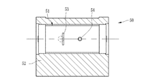
図3に示すように、ロッドインテグレータ35は内筒51に収容され、内筒51が外筒52に組込まれてインテグレータユニット50を構成し、照明光学系23に配置される。図4〜6に示すように、内筒51は遮光性を有する材質で形成され外壁面51aに調整溝53とネジ穴54が設けられている。外筒52の外壁面52aの前記調整溝53に対応する位置に前記調整溝53と係合する凸部55aを備えた位置調整治具55(図7参照)の先端部55bが差し込まれるガイド穴56が設けられ、その横に前記ネジ穴54と螺合する固定ネジ(角度調節用操作部材、固定部材)57が貫通する貫通穴58が設けられている。貫通穴58は固定ネジ57の周囲に十分な隙間が確保されるように大きく設定されている。固定ネジ57は前記外壁面52aに沿った湾曲面を有する座金59を備え、座金59によって貫通穴58を覆っている。
As shown in FIG. 3, the
次に、上記実施形態の作用について説明する。図2に戻って、投映ユニット13に映像信号が入力されると、マイクロコンピュータ20は、各部を制御して、投映を開始する。DMD駆動部39は、映像信号に基づいてDMD25を駆動する。このDMD25の駆動タイミングに合わせて、カラーホイール駆動部38はカラーホイール34を回転させ、絞り制御部46は駆動部45を介して絞り制御を行う。
Next, the operation of the above embodiment will be described. Returning to FIG. 2, when a video signal is input to the
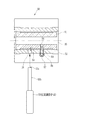
光源部22が発した光はカラーホイール34で各色に時分割されてロッドインテグレータ35の入射面35aに入射する。ロッドインテグレータ35は入射面35aから入射した光を、その内部で全反射を繰り返すことによって光束の密度を均一化し、射出面35bより射出する。射出された光はリレーレンズ36,37を通って全反射プリズム24に入射し反射面24aで反射してDMD25を照射する。
The light emitted from the light source unit 22 is time-divided into each color by the
このとき、DMD25に照射された光が、DMD25の全領域に過不足なく照射されれば問題はないが、図8に示すようにDMD25の全域25aより広い範囲25bを照射すれば照明光が無駄になり照度が落ちてしまい、図9に示すようにDMD25の全域25aより狭い範囲25cを照射すれば照射されなかった部分の画像が欠けてしまうことになる。このDMD25を照射する範囲の調整は、照明光学系23の中でのロッドインテグレータ35の相対位置を調整することで行う。
At this time, there is no problem if the light irradiated to the
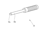
投映ユニット13によってスクリーン12に調整用の画像を投映し、この画像を見ながらロッドインテグレータ35の位置を調整する。図6に示すように、外筒52に設けられた前記ガイド穴56に位置調整治具55の先端部55bを差し込み、先端部55bの端面に設けられた凸部55aを、内筒51に設けられた前記調整溝53に嵌合させる。このとき前記固定ネジ57は緩めた状態にしておく。
An image for adjustment is projected onto the
図10〜図12に示すように、前記位置調整治具55を回転させると、前記先端部55bは外周が前記ガイド穴56によってガイドされているのでその位置で回転する。このとき前記凸部55aは、前記位置調整治具55の先端面の偏芯位置に設けられているので、前記ガイド穴56の中で円弧状に移動する。例えば、ロッドインテグレータ35を調整溝53が図10に示す位置にある状態からFの方向に移動させる場合は前記位置調整治具55を反時計方向に回転させる。凸部55aがα°回転して調整溝53をxだけ移動させると調整溝53は図11に示す位置になる。こうして内筒51がFの方向にxだけ移動するのでロッドインテグレータ35もFの方向にxだけ移動することになる。ここで、内筒51が前後に移動すると内筒51に取り付けられた固定ネジ57も移動するが、外筒52に設けられた貫通穴58は固定ネジ57の移動に対して十分な隙間が設けられているため、内筒51の移動によって固定ネジ57が貫通穴58の内壁に当接することはない。
As shown in FIGS. 10 to 12, when the
また、図10に示す位置からロッドインテグレータ35をHの方向に移動させる場合は、前記位置調整治具55を時計方向に回転させさせる。凸部55aがβ°回転して調整溝53をyだけ移動させると調整溝53は図12に示す位置になる。こうして内筒51がHの方向にyだけ移動するのでロッドインテグレータ35もHの方向にyだけ移動することになる。このようにロッドインテグレータ35の位置を移動させると前記DMD25までの距離が変化し、ロッドインテグレータ35から射出された光のDMD25を照射する範囲を調整することができる。
Further, when the
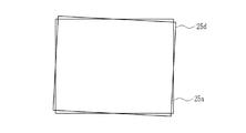
上記の調整によってスクリーン12に投映された調整用の画像がDMD25の全域25aと一致していた場合は調整完了となるが、図13に示す画像25dのように、投映された調整用の画像がDMD25の全域25aに対して僅かに回転しズレてしまう場合がある。このときは、図14に示すように、緩めてある固定ネジ57を矢印Jで示すどちらかの方向に動かして内筒51を回転させる。ここで外筒52に設けられた貫通穴58は固定ネジ57の移動に対して十分に大きいため固定ネジ57が貫通穴58の内壁に当接することはない。こうしてロッドインテグレータ35の位置調整が完了したら、固定ネジ57を回して締めつけ内筒51を外筒52に固定する。
When the adjustment image projected on the
上記実施形態では、固定ネジ57を締め付けると内筒51が外筒52に固定される構造としたが、固定ネジ57が外筒52を締め付けない構造にして、固定ネジ57を内筒51に固定された角度調整用操作部材としてのみ作用するようにしても良い。この場合は、別に固定用のネジを設けると良い。
In the above embodiment, the
上記実施形態では、画像表示パネルとしてDMDを備えているが、反射型又は透過型の液晶表示パネルを備えたものでもよい。また、プロジェクタ10は、1枚の画像表示パネルを備えた単板式であるが3枚の画像表示パネルを備えた三板式であってもよい。 In the above embodiment, the DMD is provided as the image display panel. However, the image display panel may be provided with a reflective or transmissive liquid crystal display panel. Further, the projector 10 is a single plate type having one image display panel, but may be a three plate type having three image display panels.
上記実施形態では、変調素子としてDMDを用いる場合について説明したが、本発明はこれに限るものではなく、反射コーティングが施されたガラス板による中空ロッドあるいは柱状プリズムによる中実ロッドなど、インテグレータを使用したものであれば、適用することができる。 In the above embodiment, the case where DMD is used as the modulation element has been described. However, the present invention is not limited to this, and an integrator such as a hollow rod made of a glass plate coated with a reflective coating or a solid rod made of a columnar prism is used. If so, it can be applied.
10 プロジェクタ
12 スクリーン
13 投映ユニット
15,16 ミラー
22 光源部
23 照明光学系
24 全反射プリズム
25 DMD
26 投映光学系
35 ロッドインテグレータ
35a 入射面
35b 射出面
36,37 リレーレンズ
42 投映レンズ
50 インテグレータユニット
51 内筒
51a,52a 外壁面
52 外筒
53 調整溝
54 ネジ穴
55 位置調整治具
55a 凸部
55b 先端部
56 ガイド穴
57 固定ネジ(角度調節用操作部材、固定部材)
58 貫通穴
59 座金
DESCRIPTION OF SYMBOLS 10
26 projection
58 Through
Claims (5)
前記ロッドインテグレータを固定収容した内筒と、
前記内筒を前記光軸に対して回転可能に保持するとともに前記光軸と平行な方向に直進移動可能に保持する外筒と、
を備えたことを特徴とするインテグレータユニット。 A rod integrator that is provided on the optical axis of the light source that illuminates the illumination light, and that emits the illuminance distribution of the incident light that is uniform, and
An inner cylinder fixedly housing the rod integrator;
An outer cylinder that holds the inner cylinder rotatably with respect to the optical axis and holds the inner cylinder so as to be able to move linearly in a direction parallel to the optical axis;
An integrator unit characterized by comprising
前記外筒は、前記光軸と垂直な方向から差し込まれる位置調整治具が中心位置を維持したまま回転可能に保持されるガイド穴を備えたことを特徴とする請求項1〜3のいずれかに記載のインテグレータユニット。 The inner cylinder includes an adjustment groove provided in a direction perpendicular to the optical axis on an outer wall surface,
The said outer cylinder was provided with the guide hole with which the position adjustment jig | tool inserted from the direction perpendicular | vertical to the said optical axis was rotatably hold | maintained, maintaining a center position. Integrator unit as described in
Priority Applications (1)
| Application Number | Priority Date | Filing Date | Title |
|---|---|---|---|
| JP2008029910A JP4866867B2 (en) | 2008-02-12 | 2008-02-12 | Integrator unit and projector |
Applications Claiming Priority (1)
| Application Number | Priority Date | Filing Date | Title |
|---|---|---|---|
| JP2008029910A JP4866867B2 (en) | 2008-02-12 | 2008-02-12 | Integrator unit and projector |
Publications (2)
| Publication Number | Publication Date |
|---|---|
| JP2009192555A true JP2009192555A (en) | 2009-08-27 |
| JP4866867B2 JP4866867B2 (en) | 2012-02-01 |
Family
ID=41074667
Family Applications (1)
| Application Number | Title | Priority Date | Filing Date |
|---|---|---|---|
| JP2008029910A Active JP4866867B2 (en) | 2008-02-12 | 2008-02-12 | Integrator unit and projector |
Country Status (1)
| Country | Link |
|---|---|
| JP (1) | JP4866867B2 (en) |
Cited By (2)
| Publication number | Priority date | Publication date | Assignee | Title |
|---|---|---|---|---|
| JP2012012167A (en) * | 2010-06-30 | 2012-01-19 | Fuji Xerox Co Ltd | Shaft-like member, image forming apparatus, post-treatment device, and plate-like member conveying device |
| JP2013064876A (en) * | 2011-09-16 | 2013-04-11 | Ricoh Co Ltd | Image display device |
Citations (4)
| Publication number | Priority date | Publication date | Assignee | Title |
|---|---|---|---|---|
| JPS5468644A (en) * | 1977-11-11 | 1979-06-01 | Hiroshi Ishiwata | Lens barrel fine adjusting mechanism |
| JP2001228533A (en) * | 2000-02-16 | 2001-08-24 | Seiko Epson Corp | Projector |
| JP2003156669A (en) * | 2001-11-20 | 2003-05-30 | Minolta Co Ltd | Integrator optical unit |
| JP2004085780A (en) * | 2002-08-26 | 2004-03-18 | Seiko Epson Corp | Holding mechanism for rod integrator, adjusting mechanism for illumination optical system, and projector using them |
-
2008
- 2008-02-12 JP JP2008029910A patent/JP4866867B2/en active Active
Patent Citations (4)
| Publication number | Priority date | Publication date | Assignee | Title |
|---|---|---|---|---|
| JPS5468644A (en) * | 1977-11-11 | 1979-06-01 | Hiroshi Ishiwata | Lens barrel fine adjusting mechanism |
| JP2001228533A (en) * | 2000-02-16 | 2001-08-24 | Seiko Epson Corp | Projector |
| JP2003156669A (en) * | 2001-11-20 | 2003-05-30 | Minolta Co Ltd | Integrator optical unit |
| JP2004085780A (en) * | 2002-08-26 | 2004-03-18 | Seiko Epson Corp | Holding mechanism for rod integrator, adjusting mechanism for illumination optical system, and projector using them |
Cited By (2)
| Publication number | Priority date | Publication date | Assignee | Title |
|---|---|---|---|---|
| JP2012012167A (en) * | 2010-06-30 | 2012-01-19 | Fuji Xerox Co Ltd | Shaft-like member, image forming apparatus, post-treatment device, and plate-like member conveying device |
| JP2013064876A (en) * | 2011-09-16 | 2013-04-11 | Ricoh Co Ltd | Image display device |
Also Published As
| Publication number | Publication date |
|---|---|
| JP4866867B2 (en) | 2012-02-01 |
Similar Documents
| Publication | Publication Date | Title |
|---|---|---|
| US7185990B2 (en) | Projection display apparatus | |
| JP4123295B2 (en) | Illumination apparatus, projection display apparatus, and driving method thereof | |
| TWI228634B (en) | Image display apparatus and projector | |
| JP4259567B2 (en) | Projector, projection system, program, and recording medium | |
| US7125123B2 (en) | Image projector | |
| US20070263179A1 (en) | Projection Type Display Unit | |
| JP2005234551A (en) | Projection system and method for using projection system using multiple light sources | |
| JP2005003744A (en) | Projection type picture display device | |
| TW201310158A (en) | Projection type display device and control method thereof | |
| US7825362B2 (en) | Projection device having a lens adjusting unit adjusting a focus of an adjustable collimator according to the distance between a light source and the adjustable collimator | |
| JP4679947B2 (en) | projector | |
| JP2008249747A (en) | Integrator unit | |
| JP4061898B2 (en) | Illumination apparatus, projector, and driving method thereof | |
| JP5493502B2 (en) | projector | |
| JP4866867B2 (en) | Integrator unit and projector | |
| JP3972708B2 (en) | Illumination apparatus, projection display apparatus, and driving method thereof | |
| JP2004361500A (en) | Illuminator, projection display apparatus and its driving method | |
| JPH0515036U (en) | Projector | |
| JP2006098936A (en) | Projection type display device | |
| JP4655514B2 (en) | projector | |
| JP4759936B2 (en) | Display device and projector | |
| JP4138846B2 (en) | Illumination apparatus, projector, and driving method thereof | |
| JP4079950B2 (en) | Display panel illumination optical system, color division method, and projection display apparatus having the illumination optical system | |
| KR100849433B1 (en) | Illuminator and projection display and its driving method | |
| KR100373933B1 (en) | Liquid crystal bracket for liquid crystal projector |
Legal Events
| Date | Code | Title | Description |
|---|---|---|---|
| A621 | Written request for application examination |
Free format text: JAPANESE INTERMEDIATE CODE: A621 Effective date: 20100607 |
|
| A711 | Notification of change in applicant |
Free format text: JAPANESE INTERMEDIATE CODE: A711 Effective date: 20100618 |
|
| A977 | Report on retrieval |
Free format text: JAPANESE INTERMEDIATE CODE: A971007 Effective date: 20110713 |
|
| A131 | Notification of reasons for refusal |
Free format text: JAPANESE INTERMEDIATE CODE: A131 Effective date: 20110720 |
|
| A521 | Request for written amendment filed |
Free format text: JAPANESE INTERMEDIATE CODE: A523 Effective date: 20110916 |
|
| TRDD | Decision of grant or rejection written | ||
| A01 | Written decision to grant a patent or to grant a registration (utility model) |
Free format text: JAPANESE INTERMEDIATE CODE: A01 Effective date: 20111019 |
|
| A01 | Written decision to grant a patent or to grant a registration (utility model) |
Free format text: JAPANESE INTERMEDIATE CODE: A01 |
|
| A61 | First payment of annual fees (during grant procedure) |
Free format text: JAPANESE INTERMEDIATE CODE: A61 Effective date: 20111114 |
|
| FPAY | Renewal fee payment (event date is renewal date of database) |
Free format text: PAYMENT UNTIL: 20141118 Year of fee payment: 3 |
|
| R150 | Certificate of patent or registration of utility model |
Ref document number: 4866867 Country of ref document: JP Free format text: JAPANESE INTERMEDIATE CODE: R150 Free format text: JAPANESE INTERMEDIATE CODE: R150 |
|
| R250 | Receipt of annual fees |
Free format text: JAPANESE INTERMEDIATE CODE: R250 |
|
| R250 | Receipt of annual fees |
Free format text: JAPANESE INTERMEDIATE CODE: R250 |
|
| R250 | Receipt of annual fees |
Free format text: JAPANESE INTERMEDIATE CODE: R250 |
|
| R250 | Receipt of annual fees |
Free format text: JAPANESE INTERMEDIATE CODE: R250 |
|
| R250 | Receipt of annual fees |
Free format text: JAPANESE INTERMEDIATE CODE: R250 |
|
| R250 | Receipt of annual fees |
Free format text: JAPANESE INTERMEDIATE CODE: R250 |
|
| R250 | Receipt of annual fees |
Free format text: JAPANESE INTERMEDIATE CODE: R250 |
|
| R250 | Receipt of annual fees |
Free format text: JAPANESE INTERMEDIATE CODE: R250 |
|
| R250 | Receipt of annual fees |
Free format text: JAPANESE INTERMEDIATE CODE: R250 |
|
| R250 | Receipt of annual fees |
Free format text: JAPANESE INTERMEDIATE CODE: R250 |