JP2005234551A - Projection system and method for using projection system using multiple light sources - Google Patents
Projection system and method for using projection system using multiple light sources Download PDFInfo
- Publication number
- JP2005234551A JP2005234551A JP2005011715A JP2005011715A JP2005234551A JP 2005234551 A JP2005234551 A JP 2005234551A JP 2005011715 A JP2005011715 A JP 2005011715A JP 2005011715 A JP2005011715 A JP 2005011715A JP 2005234551 A JP2005234551 A JP 2005234551A
- Authority
- JP
- Japan
- Prior art keywords
- light
- projection system
- illumination
- light source
- aperture
- Prior art date
- Legal status (The legal status is an assumption and is not a legal conclusion. Google has not performed a legal analysis and makes no representation as to the accuracy of the status listed.)
- Pending
Links
Images


Classifications
-
- G—PHYSICS
- G03—PHOTOGRAPHY; CINEMATOGRAPHY; ANALOGOUS TECHNIQUES USING WAVES OTHER THAN OPTICAL WAVES; ELECTROGRAPHY; HOLOGRAPHY
- G03B—APPARATUS OR ARRANGEMENTS FOR TAKING PHOTOGRAPHS OR FOR PROJECTING OR VIEWING THEM; APPARATUS OR ARRANGEMENTS EMPLOYING ANALOGOUS TECHNIQUES USING WAVES OTHER THAN OPTICAL WAVES; ACCESSORIES THEREFOR
- G03B21/00—Projectors or projection-type viewers; Accessories therefor
- G03B21/14—Details
- G03B21/20—Lamp housings
- G03B21/2006—Lamp housings characterised by the light source
- G03B21/2013—Plural light sources
-
- G—PHYSICS
- G03—PHOTOGRAPHY; CINEMATOGRAPHY; ANALOGOUS TECHNIQUES USING WAVES OTHER THAN OPTICAL WAVES; ELECTROGRAPHY; HOLOGRAPHY
- G03B—APPARATUS OR ARRANGEMENTS FOR TAKING PHOTOGRAPHS OR FOR PROJECTING OR VIEWING THEM; APPARATUS OR ARRANGEMENTS EMPLOYING ANALOGOUS TECHNIQUES USING WAVES OTHER THAN OPTICAL WAVES; ACCESSORIES THEREFOR
- G03B21/00—Projectors or projection-type viewers; Accessories therefor
- G03B21/14—Details
- G03B21/20—Lamp housings
- G03B21/2053—Intensity control of illuminating light
-
- G—PHYSICS
- G03—PHOTOGRAPHY; CINEMATOGRAPHY; ANALOGOUS TECHNIQUES USING WAVES OTHER THAN OPTICAL WAVES; ELECTROGRAPHY; HOLOGRAPHY
- G03B—APPARATUS OR ARRANGEMENTS FOR TAKING PHOTOGRAPHS OR FOR PROJECTING OR VIEWING THEM; APPARATUS OR ARRANGEMENTS EMPLOYING ANALOGOUS TECHNIQUES USING WAVES OTHER THAN OPTICAL WAVES; ACCESSORIES THEREFOR
- G03B21/00—Projectors or projection-type viewers; Accessories therefor
- G03B21/14—Details
- G03B21/20—Lamp housings
- G03B21/208—Homogenising, shaping of the illumination light
-
- H—ELECTRICITY
- H04—ELECTRIC COMMUNICATION TECHNIQUE
- H04N—PICTORIAL COMMUNICATION, e.g. TELEVISION
- H04N5/00—Details of television systems
- H04N5/74—Projection arrangements for image reproduction, e.g. using eidophor
- H04N5/7416—Projection arrangements for image reproduction, e.g. using eidophor involving the use of a spatial light modulator, e.g. a light valve, controlled by a video signal
-
- H—ELECTRICITY
- H04—ELECTRIC COMMUNICATION TECHNIQUE
- H04N—PICTORIAL COMMUNICATION, e.g. TELEVISION
- H04N9/00—Details of colour television systems
- H04N9/12—Picture reproducers
- H04N9/31—Projection devices for colour picture display, e.g. using electronic spatial light modulators [ESLM]
- H04N9/3141—Constructional details thereof
- H04N9/315—Modulator illumination systems
- H04N9/3155—Modulator illumination systems for controlling the light source
Abstract
Description
本発明は、画像を投影するための投影システムの分野に関する。より具体的には、本発明は透過型または反射型の光バルブを用いるプロジェクタのための高出力照明システム、およびそれを動作する方法に関する。 The present invention relates to the field of projection systems for projecting images. More specifically, the present invention relates to a high power illumination system for a projector using a transmissive or reflective light valve and a method of operating the same.
発明の背景
大画面、高輝度の電子投影表示装置は、たとえばビジネス、教育、広告、娯楽、シミュレーション、状況および情報の電子プレゼンテーションといった、広範囲にわたる異なる分野で役に立つ。
BACKGROUND OF THE INVENTION Large screen, high brightness electronic projection displays are useful in a wide range of different fields, for example, business, education, advertising, entertainment, simulation, situation and information electronic presentation.
本投影システムの高輝度性という要件を満たすため、高レベルの出力の光源が必要である。このことは、しばしば小型の投影表示装置の実現を阻害する。 In order to meet the high brightness requirement of the projection system, a light source with a high level of output is required. This often hinders the realization of small projection display devices.
投影システムでは、典型的には250Wの出力を有するランプが使われる。光束の増大は、ランプの劣化を加速してランプの寿命を著しく短縮するような、ランプの内部構造を変えることなく出力レベルを上げる方法か、または、ランプのサイズを著しく増大させて投影システムの小型化を制限するような、ランプの内部構造を変える方法、すなわち発光素子の長さを拡張する方法の、いずれかによって実施され得る。これらのいずれの解決方法によっても、小型で耐久性のある投影システムを得ることはできない。 In a projection system, a lamp with an output of typically 250 W is used. Increasing the luminous flux is a way to increase the power level without changing the internal structure of the lamp, which accelerates lamp degradation and significantly shortens the lamp life, or significantly increases the size of the lamp to increase the It can be implemented either by changing the internal structure of the lamp, ie, by extending the length of the light emitting element, so as to limit miniaturization. Neither of these solutions can provide a compact and durable projection system.
欧州特許出願EP0683425 A1において、投影システムのための複数のランプを用いる方式が記載されている。この出願では、2つまたはそれ以上のランプと、光を透過する光学システムと、光バルブと、投影レンズとを有する投影システムが説明される。ランプは並んで配置され、システムをより小型にできる。具体的実施例において、光を透過する光学システムは、光結合器としてのレンズアレイのセットを複数含む。レンズアレイからの像は追加のレンズによって光バルブに集束する。紫外線(UV)および/または赤外線(IR)放射を光路から取除くために、UV/IRフィルタがランプに隣接して配置される。しかし、IR放射の反射がランプに戻るため、ランプの劣化の増大を招く。 In European patent application EP 0683425 A1, a scheme using a plurality of lamps for a projection system is described. In this application, a projection system is described that includes two or more lamps, an optical system that transmits light, a light bulb, and a projection lens. The lamps are arranged side by side, making the system more compact. In a specific embodiment, an optical system that transmits light includes a plurality of sets of lens arrays as optical couplers. The image from the lens array is focused on the light valve by an additional lens. In order to remove ultraviolet (UV) and / or infrared (IR) radiation from the optical path, a UV / IR filter is placed adjacent to the lamp. However, the reflection of IR radiation returns to the lamp, leading to increased lamp degradation.
さらに、今日の投影システムは、投影システム全体として十分小型化できていないという欠点もある。光バルブの最適な照明の達成、すなわち光バルブの熱負荷を減らすととともに光源の最適な光出力を光バルブに集めることも、依然できていない。 Furthermore, today's projection system has a drawback that it cannot be sufficiently miniaturized as a whole projection system. It has not yet been possible to achieve optimal illumination of the light bulb, ie to reduce the light load on the light bulb and to collect the optimal light output of the light source in the light bulb.
発明の概要
本発明の1つの目的は、向上された投影画像を得るために異なる光源の光出力が用いられる、複数光源の投影システムおよびその動作方法を提供することである。
SUMMARY OF THE INVENTION One object of the present invention is to provide a multiple light source projection system and method of operation thereof in which the light output of different light sources is used to obtain an improved projected image.
本発明のさらに他の目的は、コントラストおよび輝度の双方を独立に調節できる、複数光源の投影システムおよびその動作方法を提供することである。 Still another object of the present invention is to provide a multiple light source projection system and a method of operating the same that can independently adjust both contrast and brightness.
本発明のさらに他の目的は、光バルブアセンブリの照明が最適化されること、すなわち、光バルブアセンブリの照明がより鮮明な輪郭を得られること、およびそれを達成する方法を提供することである。 Yet another object of the present invention is to optimize the illumination of the light valve assembly, i.e. to provide a sharper contour for the illumination of the light valve assembly and to provide a method for achieving it. .
本発明のさらに他の目的は、使用光源の冷却が改善された、複数光源の投影システムおよびその動作方法を提供することである。 Still another object of the present invention is to provide a multiple light source projection system and a method of operating the same, with improved cooling of the light source used.
上記の目的は、本発明による方法および装置によって達成される。 The above objective is accomplished by a method and device according to the present invention.
本発明は画像を投影するための投影システムに関し、前記投影システムは、光バルブアセンブリと、少なくとも2つの光源と、アパーチャ手段とを含み、前記少なくとも2つの光源は、前記アパーチャ手段に対して照明ビームを発することにより各々が光バルブアセンブリ全体を同時に照らすよう適合され、前記システムは、少なくとも1つの前記光源の前記照明ビームの断面をアパーチャ手段の中または近くで調節するための調節手段を含む。前記アパーチャ手段は、リレー光学系が設けられることによって決定されてもよい。前記アパーチャ手段の中または近くということは、アパーチャの中で、または実質的にアパーチャ手段に隣接して、すなわち、その場所の照明がアパーチャの中の照明と実質的に類似しかつ同じ特性を有するような、対応する領域においてということを含む。アパーチャ手段の中での調節は、断面をアパーチャの中で調節すること、たとえばアパーチャ手段のスリット内に手段を配置し、もしくはそれを動かすことによって、または、たとえばアパーチャ手段を傾けることによって行われる。アパーチャ手段の中または近くでの調節は、たとえばアパーチャ手段に隣接して手段を配置、または動かすことによって行われてもよい。前記アパーチャ手段は、アパーチャを有するアパーチャ板でもよい。前記少なくとも2つの光源の各々において、前記断面は、前記アパーチャ手段の中または近くで、他の前記光源の照明ビームの断面と重ならなくてもよい。アパーチャ手段の中または近くで断面を調節することは、前記アパーチャ手段のアパーチャを通って前記アパーチャ手段の前記アパーチャの面積で平均面に直角に投影される、照明ビームの断面の投影面積の率を変更することを含む。アパーチャ手段の中または近くで断面を調節することは、光バルブアセンブリにおいて生成される像のシャインプルフ効果(Scheimpflug effect)を補正するために、前記システムの光軸に対して前記アパーチャ手段を傾けることを含む。前記調節手段は、少なくとも1つの前記光源の照明ビームの断面の少なくとも一部をブロックするブロック手段を含む。前記ブロック手段はハイコントラスト板でもよい。前記ブロックされる部分は、光バルブアセンブリで入射最小角を有する照明光を伴う照明ビームの部分でもよい。前記調節手段は、コントラストを変えずに光バルブアセンブリの照明を低減するための、調節可能な照明低減手段を含んでもよい。前記調節可能な照明低減手段は、光バルブアセンブリに到達する照明光の平均入射角が、照明の一部をブロックすることなく光バルブアセンブリに到達する照明光の平均入射角に実質的に等しくなるように、照明ビームの少なくとも一部をアパーチャ手段の中または近くでブロックできるようにしてもよい。照明ビームの前記ブロックされる部分は、光バルブアセンブリにおいて入射角が大きい照明光と、光バルブアセンブリにおいて入射角が小さい照明光とで等しい面積部分がブロックされてもよい。前記投影システムは、異なる波長領域のビームの中で前記照明ビームを分光する分光手段を含み、前記異なる波長領域のビームは異なる光バルブアセンブリを照らすよう適合され、前記調節手段はダイクロイックシフトを受ける照明ビームの光の量を低減するための手段を含み、前記ダイクロイックシフトは前記照明ビームを分光するための前記手段によってもたらされる。ダイクロイックシフトを受けやすい照明ビームの光の量を低減するための前記手段は、照明の一部をアパーチャ手段の中または近くでブロックするための手段を含む。前記調節手段は、前記システムの光軸のまわりに前記少なくとも2つの光源を回転させるための回転手段を含む。前記回転は、リレー光学系の光軸のまわりの回転であってもよい。前記調節手段は、アパーチャ手段と近いが同じではない場所に配置される、拡散器を含んでもよい。この配置は、埃またはごみの粒を写すことを避けるためになされる。 The present invention relates to a projection system for projecting an image, the projection system comprising a light valve assembly, at least two light sources, and aperture means, the at least two light sources being an illumination beam for the aperture means. Each of which is adapted to simultaneously illuminate the entire light valve assembly, the system including adjusting means for adjusting the cross section of the illumination beam of at least one of the light sources in or near the aperture means. The aperture means may be determined by providing a relay optical system. In or near the aperture means means within the aperture or substantially adjacent to the aperture means, i.e., the illumination at that location is substantially similar and has the same characteristics as the illumination in the aperture In the corresponding region. The adjustment in the aperture means is effected by adjusting the cross-section in the aperture, for example by placing or moving the means in the slit of the aperture means or by tilting the aperture means, for example. Adjustments in or near the aperture means may be made, for example, by placing or moving the means adjacent to the aperture means. The aperture means may be an aperture plate having an aperture. In each of the at least two light sources, the cross section may not overlap with the cross section of the illumination beam of the other light source in or near the aperture means. Adjusting the cross-section in or near the aperture means determines the ratio of the projected area of the cross-section of the illumination beam that is projected through the aperture of the aperture means at right angles to the average plane at the area of the aperture of the aperture means. Including changing. Adjusting the cross-section in or near the aperture means tilts the aperture means relative to the optical axis of the system to compensate for the image Scheimpflug effect generated in the light valve assembly. including. The adjusting means includes blocking means for blocking at least part of the cross section of the illumination beam of at least one of the light sources. The blocking means may be a high contrast plate. The blocked portion may be a portion of the illumination beam with illumination light having a minimum incident angle at the light valve assembly. The adjusting means may include adjustable illumination reducing means for reducing the illumination of the light valve assembly without changing the contrast. The adjustable illumination reduction means is such that the average incident angle of illumination light reaching the light valve assembly is substantially equal to the average incident angle of illumination light reaching the light valve assembly without blocking part of the illumination. As such, at least a portion of the illumination beam may be blocked in or near the aperture means. The portion of the illumination beam that is blocked may be blocked by an area having the same incident angle between the illumination light having a large incident angle in the light valve assembly and the illumination light having a small incident angle in the light valve assembly. The projection system includes spectroscopic means for splitting the illumination beam in beams of different wavelength regions, the beams of different wavelength regions are adapted to illuminate different light valve assemblies, and the adjusting means is an illumination subject to dichroic shift Including means for reducing the amount of light in the beam, wherein the dichroic shift is provided by the means for spectroscopically illuminating the illumination beam. Said means for reducing the amount of light of the illumination beam that is susceptible to dichroic shift includes means for blocking a part of the illumination in or near the aperture means. The adjusting means includes rotating means for rotating the at least two light sources about the optical axis of the system. The rotation may be rotation around the optical axis of the relay optical system. Said adjustment means may comprise a diffuser arranged at a location close to but not the same as the aperture means. This arrangement is made to avoid copying dust or dirt particles.
本発明は、複数光源の投影システムを用いるための方法に関し、前記方法は、光ビーム
を生成するために少なくとも2つの光源の各々を駆動するステップと、前記各光源から前記光ビームを単一の照明ビームに集光するステップと、前記単一の照明ビームで光バルブアセンブリを照らすステップとを含み、前記方法は、前記単一の照明ビームで光バルブアセンブリを照らす前に、少なくとも1つの前記光源の前記光ビームの断面をアパーチャ手段の中または近くで調節するステップをさらに含む。少なくとも1つの前記光源の前記光ビームの前記断面を調節するステップは、光バルブアセンブリにおいて生成される像のシャインプルフ効果を補正するために、前記システムの光軸に対して前記アパーチャ手段を傾けるステップを含む。少なくとも1つの前記光源の前記光ビームの前記断面を調節するステップは、少なくとも1つの前記光源の光ビームの断面の少なくとも一部をブロックするステップを含む。前記ブロックするステップは、生成される像のコントラストまたは輝度を変えるために行われてもよい。コントラストまたは輝度は独立に変えられる。少なくとも1つの前記光源の光ビームの断面の少なくとも一部をブロックするステップは、光バルブアセンブリで最小入射角を有する照明光を含む光ビームの前記一部をブロックするステップを含む。少なくとも1つの前記光源の光ビームの断面の少なくとも一部をブロックするステップは、コントラストを変えずに光ビームの前記一部をブロックするステップを含む。少なくとも1つの前記光源の光ビームの断面の少なくとも一部をブロックするステップは、ダイクロイックシフトを受けやすい光ビームの一部をブロックするステップを含む。少なくとも1つの前記光源の前記光ビームの断面をアパーチャ手段の中または近くで調節するステップは、前記システムの光軸のまわりに前記少なくとも2つの光源を回転させるステップを含む。これは、投影システムの製造過程で実施されてもよい。
The present invention relates to a method for using a multiple light source projection system, the method driving each of at least two light sources to generate a light beam, and a single light beam from each light source. Condensing into an illumination beam and illuminating a light valve assembly with the single illumination beam, the method including illuminating the light valve assembly with the single illumination beam Adjusting the cross-section of the light beam in or near the aperture means. Adjusting the cross-section of the light beam of at least one light source tilts the aperture means relative to the optical axis of the system to correct for the Shine-Pruff effect of the image generated in the light valve assembly. including. Adjusting the cross section of the light beam of at least one light source includes blocking at least a portion of the cross section of the light beam of at least one light source. The blocking step may be performed to change the contrast or brightness of the generated image. Contrast or brightness can be changed independently. Blocking at least a portion of the cross section of the light beam of the at least one light source includes blocking the portion of the light beam that includes illumination light having a minimum incident angle at the light valve assembly. Blocking at least a portion of the cross section of the light beam of the at least one light source includes blocking the portion of the light beam without changing contrast. Blocking at least a portion of the cross section of the light beam of the at least one light source includes blocking a portion of the light beam that is susceptible to dichroic shift. Adjusting the cross-section of the light beam of at least one of the light sources in or near aperture means includes rotating the at least two light sources about the optical axis of the system. This may be performed during the manufacturing process of the projection system.
少なくとも1つの前記光源の前記光ビームの断面をアパーチャ手段の中または近くで調節するステップは、少なくとも1つの前記光源の光ビームの少なくとも一部を拡散するステップを含む。方法は、前記照らされた光バルブアセンブリから投影レンズを用いて前記画像を投影するステップをさらに含む。 Adjusting the cross section of the light beam of at least one of the light sources in or near aperture means includes diffusing at least a portion of the light beam of at least one of the light sources. The method further includes projecting the image from the illuminated light valve assembly using a projection lens.
本発明はさらに、画像を投影するための投影システムに関する。投影システムは、光バルブアセンブリと、赤外光を生成し、光バルブアセンブリ全体を各々が同時に照らすよう調節された少なくとも2つの光源とを含む。投影システムは、第1のレンズアレイおよび第2のレンズアレイを有するレンズアレイシステムを、各光源に対して含む。投影システムは、光源によって発せられる赤外線の少なくとも一部は反射されて光源に戻ることがないよう配置される、赤外放射フィルタリング手段を、各光源に対して含む。赤外放射の一部は赤外放射の少なくとも50%であり、好ましくは赤外放射の少なくとも80%であり、より好ましくは赤外放射の少なくとも99%であり、最も好ましくは赤外放射の100%である。赤外放射フィルタリング手段は第1のレンズアレイと第2のレンズアレイとの間に配置されてもよい。赤外放射フィルタリングのための手段は、コールドミラーでもよい。 The invention further relates to a projection system for projecting an image. The projection system includes a light valve assembly and at least two light sources that are adapted to generate infrared light and each illuminate the entire light valve assembly simultaneously. The projection system includes a lens array system having a first lens array and a second lens array for each light source. The projection system includes for each light source infrared radiation filtering means arranged so that at least part of the infrared light emitted by the light source is reflected and does not return to the light source. A portion of the infrared radiation is at least 50% of the infrared radiation, preferably at least 80% of the infrared radiation, more preferably at least 99% of the infrared radiation, and most preferably 100% of the infrared radiation. %. The infrared radiation filtering means may be disposed between the first lens array and the second lens array. The means for infrared radiation filtering may be a cold mirror.
投影システムは、異なる光源からそれぞれ出る複数の光ビームから形成され、光バルブアセンブリのアパーチャ板のアパーチャによって調節される、照明ビームの投影に適している。光バルブアセンブリを駆動することによってサイズが変更可能な画像が生成され、投影システムの投影レンズにより画面に投影される。 The projection system is suitable for the projection of an illumination beam formed from a plurality of light beams each coming from different light sources and adjusted by the apertures of the aperture plate of the light valve assembly. By driving the light valve assembly, a resizable image is generated and projected onto the screen by the projection lens of the projection system.
投影システムは、少なくとも1つの光源の光出力を計測するためのセンサをさらに含む。センサは、たとえばコールドミラーのような赤外放射フィルタリング手段の後ろに配置され得る。したがって、コールドミラーは光バルブのセットを照らすために必要な光ビームがコールドミラーに反射されるように配置され、一方、赤外放射はコールドミラーで透過されるので、コールドミラーの下流にある反射光の経路には赤外放射はもはや発生しない。前記少なくとも2つの光源のうち少なくとも1つの光源の光出力の計測は、コールドミラーを透過する赤外放射に基づいて行うことができる。 The projection system further includes a sensor for measuring the light output of the at least one light source. The sensor can be placed behind an infrared radiation filtering means such as a cold mirror. Thus, the cold mirror is positioned so that the light beam needed to illuminate the set of light valves is reflected off the cold mirror, while the infrared radiation is transmitted through the cold mirror, so that the reflection downstream of the cold mirror is Infrared radiation no longer occurs in the light path. The light output of at least one of the at least two light sources can be measured based on infrared radiation that passes through a cold mirror.
投影システムは、各光源のための駆動手段と、センサと前記各光源の駆動手段との間のフィードバック手段とを含み、前記各光源の光出力を制御する。投影システムは、前記各光源に隣接する紫外線フィルタを含んでもよい。 The projection system includes drive means for each light source and feedback means between the sensor and the drive means for each light source to control the light output of each light source. The projection system may include an ultraviolet filter adjacent to each light source.
本発明は、画像を投影するための投影システムにさらに関し、前記投影システムは、光バルブアセンブリと、各々が光バルブアセンブリ全体を同時に照らすよう調節された少なくとも2つの光源と、アパーチャ手段とを含む。投影システムは、前記照明を前記光バルブアセンブリに集束するためのリレー光学系をさらに含む。リレー光学系は、光路上でアパーチャ手段の下流に配置される。リレー光学系は、リレー光学系の瞳の収差を最小化するために材料の選択、および構造に基づいて最適化される。光バルブアセンブリは、可変ミラーデバイスアセンブリであってもよい。少なくとも2つの光源のうち少なくとも1つが、発光装置のアレイであってもよい。 The invention further relates to a projection system for projecting an image, said projection system comprising a light valve assembly, at least two light sources each adjusted to simultaneously illuminate the entire light valve assembly, and aperture means. . The projection system further includes relay optics for focusing the illumination onto the light valve assembly. The relay optical system is disposed downstream of the aperture means on the optical path. The relay optics are optimized based on material selection and structure to minimize the pupil aberration of the relay optics. The light valve assembly may be a variable mirror device assembly. At least one of the at least two light sources may be an array of light emitting devices.
投影システムは、各光源が照明のどの部分を担うかを変更するために、リレー光学系の光軸のまわりに2つの光源が回転できるようさらに調節されてもよい。この回転は、必要とされる投影システムの要件に応じて、投影システムの製造過程で実施されてもよい。 The projection system may be further adjusted to allow the two light sources to rotate about the optical axis of the relay optics to change which part of the illumination each light source carries. This rotation may be performed during the manufacturing process of the projection system, depending on the requirements of the projection system required.
本発明は、画像を投影するための投影システムにさらに関し、投影システムは、光バルブアセンブリと、各々が光バルブアセンブリ全体を同時に照らすよう調節された少なくとも2つの光源と、アパーチャ手段とを含む。投影システムは、コントラストを変えることなく光バルブアセンブリの照明を低減するための、調節可能な照明低減手段をさらに含む。 The invention further relates to a projection system for projecting an image, the projection system including a light valve assembly, at least two light sources each adjusted to simultaneously illuminate the entire light valve assembly, and aperture means. The projection system further includes adjustable illumination reduction means for reducing the illumination of the light valve assembly without changing the contrast.
本発明は、画像を投影するための投影システムにさらに関し、投影システムは、光バルブアセンブリと、各々が光バルブアセンブリ全体を同時に照らすよう調節された少なくとも2つの光源と、照らされた光バルブアセンブリによって画面に生成される拡張可能な前記画像を投影するための投影レンズとを含む。少なくとも2つの光源の少なくとも1つは、発光装置のアレイである。前記少なくとも2つの光源の各々が発光装置のアレイであってもよい。 The invention further relates to a projection system for projecting an image, the projection system comprising a light valve assembly, at least two light sources each adjusted to simultaneously illuminate the entire light valve assembly, and an illuminated light valve assembly. And a projection lens for projecting the expandable image generated on the screen. At least one of the at least two light sources is an array of light emitting devices. Each of the at least two light sources may be an array of light emitting devices.
本発明はさらに、マルチカラー画像を投影するための投影システムに関する。投影システムは、単一の照明ビームを生成するよう調節される少なくとも2つの光源と、リレー光学系と、異なる波長または波長領域のビームの中で前記照明ビームを分光するための手段とを含み、異なる波長または波長領域のビームは異なる光バルブアセンブリを照らす。投影システムは、ダイクロイックシフトを受けやすい照明ビームの光の量を低減するための手段をさらに含み、ダイクロイックシフトは、前記照明ビームを分光するための手段によって少なくとも部分的にもたらされる。リレー光学系は、投影システムのアパーチャ手段の下流に配置されてもよい。ダイクロイックシフトを受けやすい照明ビームの光の量を低減する手段は、リレー光学系の開口絞りに設置される、照明ビームの一部をブロックするための手段を含んでもよい。 The invention further relates to a projection system for projecting multicolor images. The projection system includes at least two light sources that are adjusted to produce a single illumination beam, relay optics, and means for splitting the illumination beam among beams of different wavelengths or wavelength ranges, Beams of different wavelengths or wavelength regions illuminate different light valve assemblies. The projection system further includes means for reducing the amount of light in the illumination beam that is susceptible to dichroic shift, the dichroic shift being provided at least in part by means for spectroscopically illuminating the illumination beam. The relay optical system may be arranged downstream of the aperture means of the projection system. The means for reducing the amount of light of the illumination beam that is susceptible to dichroic shift may include means for blocking a portion of the illumination beam that is installed at the aperture stop of the relay optical system.
本発明は画像を投影するための投影システムにさらに関し、投影システムは、光バルブアセンブリと、各々が光バルブアセンブリ全体を同時に照らすよう調節された少なくとも2つの光源と、アパーチャ手段とを含む。 The invention further relates to a projection system for projecting an image, the projection system including a light valve assembly, at least two light sources each adjusted to illuminate the entire light valve assembly simultaneously, and aperture means.
本発明は、複数光源の投影システムを使うための方法にさらに関し、方法は、光ビームを生成するために前記少なくとも2つの光源を駆動するステップと、前記光ビームを前記各光源から単一の照明ビームに集光するステップと、前記単一の照明ビームで光バルブアセンブリを照らすステップと、前記照らされた光バルブアセンブリから投影レンズを用い
て前記画像を投影するステップとを含む。方法は、前記光ビームを前記各光源から集光する前に、前記各光源の各光ビームから赤外放射をフィルタリングするステップをさらに含み、フィルタリングされた赤外放射の少なくとも一部は光源に再度導かれることはない。フィルタリングは、フィルタリング手段の下流の光路から赤外放射の少なくとも一部を取除くことによって行われる。赤外放射の一部は赤外放射の少なくとも50%であり、好ましくは赤外放射の少なくとも80%であり、より好ましくは赤外放射の少なくとも99%であり、最も好ましくは赤外放射の100%である。方法は、前記赤外放射をフィルタリングし、再度導いた後、前記各光源からの光出力を計測するステップと、対応して前記各光源の光出力を最適化するために前記少なくとも2つの光源の各々の駆動を調節するステップとをさらに含んでもよい。
The invention further relates to a method for using a multiple light source projection system, the method comprising: driving the at least two light sources to generate a light beam; and Focusing on an illumination beam, illuminating a light valve assembly with the single illumination beam, and projecting the image from the illuminated light valve assembly using a projection lens. The method further includes filtering infrared radiation from each light beam of each light source prior to collecting the light beam from each light source, wherein at least a portion of the filtered infrared radiation is again applied to the light source. There is no guidance. Filtering is performed by removing at least part of the infrared radiation from the optical path downstream of the filtering means. A portion of the infrared radiation is at least 50% of the infrared radiation, preferably at least 80% of the infrared radiation, more preferably at least 99% of the infrared radiation, and most preferably 100% of the infrared radiation. %. The method includes filtering and re-directing the infrared radiation and then measuring the light output from each of the light sources, and correspondingly, to optimize the light output of each of the light sources. And adjusting each drive.
本発明の利点の1つは、小型で、照明が最適化された投影システムを提供することである。 One advantage of the present invention is that it provides a projection system that is compact and optimized for illumination.
本発明のさらなる利点は、反射型光バルブおよび透過型光バルブの双方が利用できることである。 A further advantage of the present invention is that both reflective and transmissive light valves can be utilized.
本発明の具体的なさらなる利点は、光源の選択に大きな自由度があることである。 A further particular advantage of the present invention is that there is great freedom in the choice of light source.
異なる使用光源の光出力が、たとえば、モニタリングされ、使われ、調節され、すなわち同期され、および/または最適化されるなど、制御できることがさらなる利点である。 It is a further advantage that the light output of the different used light sources can be controlled, eg monitored, used, adjusted, ie synchronized and / or optimized.
この分野の方法および装置は常に向上し、変化し、進化しているが、本概念は従前の慣行から離脱して実質的に新規な改良を示し、結果としてこのような装置をより効率的で安定した、信頼性の高いものとして提供すると考えられる。 Although methods and devices in this area are constantly improving, changing and evolving, this concept departs from conventional practice and represents a substantially new improvement, resulting in more efficient such devices. It is considered to be provided as stable and reliable.
本発明の教示により、投影表示システムを使って画像を投影するための、向上された方法および装置の設計が提供される。 The teachings of the present invention provide an improved method and apparatus design for projecting an image using a projection display system.
本発明のこれらの、および他の特徴、特性、ならびに利点は、本発明の趣旨を例示する付属の図面とともに以下に述べる詳細な説明から明らかにされる。この説明は本発明の範囲を限定することなく、例示としてのみ与えられる。下記に示される参照番号は付随する図面と関連付けられる。 These and other features, characteristics and advantages of the present invention will become apparent from the detailed description set forth below when taken in conjunction with the accompanying drawings which illustrate the spirit of the invention. This description is given for the sake of example only, without limiting the scope of the invention. The reference numerals shown below are associated with the accompanying drawings.
図示される実施例の説明
本発明は特定の実施例および図面に関連して説明されるが、本発明はそれらに限定されるものではなく、請求項によってのみ限定される。記載の図面は単に概略図であり、限定的ではない。図面の中で、いくつかの要素のサイズは誇張されており、図示する目的から、縮尺どおりに描かれていないものもある。本発明の説明および請求項で使われる「含む」の用語は、他の要素またはステップを排除するものではない。
DESCRIPTION OF EXEMPLARY EMBODIMENTS Although the invention will be described in conjunction with the specific embodiments and drawings, the invention is not limited thereto but only by the claims. The drawings described are only schematic and are non-limiting. In the drawings, the size of some of the elements is exaggerated and some are not drawn to scale for illustrative purposes. The term “comprising”, used in the description and claims of the present invention, does not exclude other elements or steps.
さらに、説明および請求項中の、第1、第2、第3などの用語は、類似の要素からの区別のために使われ、必ずしもその順序、または時系列を表わすものではない。このように使われる用語は適切な状況のもとで交換が可能であり、ここに記載された本発明の実施例は、ここに記載され、または図示された以外の他の順序で動作してもよいことが理解される。 Further, terms such as “first”, “second”, “third”, etc. in the description and the claims are used for distinction from similar elements, and do not necessarily indicate their order or time series. The terms used in this manner are interchangeable under appropriate circumstances, and the embodiments of the invention described herein operate in other orders than described or illustrated herein. It is understood that
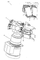
第1の実施例において、本発明による投影システム100が図示される。投影システム100は、少なくとも2つの光源1と、集束システムと、アパーチャ3が配置されるとこ
ろに焦点を有する集光レンズ2または集光レンズのセットと、空間光変調器とも呼ばれる光バルブ4のセットと、投影レンズ5とを含む。集束システムは、第1のレンズアレイ6および第2のレンズアレイ7を含む。投影システムには、典型的には紫外線(UV)/赤外線(IR)フィルタが光源に隣接して使われるが、本発明の具体的な特徴として、投影システム100は、IR放射をシステムから取除くために第1のレンズアレイ6と第2のレンズアレイ7との間にコールドミラー8を含む。本発明の本実施例による投影システム100は、光源1に隣接するIRフィルタを含まず、代わりに赤外光をフィルタリングし、または取除き、または分岐させるための手段を含み、光源から発せられた赤外光が反射されて光源に戻ることを抑制する。
In a first embodiment, a
本実施例の投影システムは、さらに任意で、光源1に隣接するUVフィルタ9と、調節可能な調光器10と、拡散器11と、リレー光学系12と、リレー光学系の開口絞り13と、および/またはハイコントラスト板14とを含んでもよい。コールドミラー8は、反射されて光源1に戻るIR光による、光源1の劣化を回避する。
The projection system of the present embodiment further optionally includes a
各光源1は平行な光束を投影する。これらの光源1はランプ20または発光装置21のアレイのいずれか一方であってもよい。図2では、ランプ20が使われる構成の一部を示す。使われるランプ20は投影システムで使われる従来のランプのどれでもよく、たとえば、キセノンランプ、高圧水銀ランプ、ハロゲンランプまたはメタルハライドランプなどであってもよいが、これらに限定されない。本発明の投影システムは少なくともデュアル光源システム、すなわち使用光源1が少なくとも2つあるシステムなので、同じ光束を得るために、単光源の投影システムと比較して各使用ランプの出力が低くてすみ、または単光源の投影システムの場合よりも得られる総光束が大きくなる。光源1はさらに、発光装置21のアレイまたはグループであってもよく、すなわち1つの光源が発光装置21の1つのアレイまたはグループと対応してもよい。これらの装置は、たとえば発光ダイオードまたは有機発光ダイオードでもよい。発光装置のアレイを使うための構成は図3に示される。後者はシステムをより小型化でき、これは顕著な利点となる。
Each
使用光源1の個数は2つより多くてもさらによい。光源1の典型的な個数は、投影レンズ5の瞳の最適な充填度が得られるよう選択される。これは、たとえば4個の光源が2×2のパターンで、6個の光源が2×3もしくは3×2のパターンで、または9個の光源が3×3のパターンで配置されてもよい。さらに他の個数の光源1が使われてもよいが、瞳の最適な充填度が得られるので、2個,4個,6個または9個の光源の使用が好ましい。このように、平行な光束を出す光源1から始まって、光源1の選択には多大な自由度がある。放物面反射体のランプが好ましいが、LEDのアレイもさらに使用できる。ランプが使われる場合、使われる反射体の形状は放物面と異なっていてもさらによい。
The number of used
各光束は長方形の小レンズからなる古典的なレンズアレイシステムを通り、そこで第1のレンズアレイ6が、典型的には長方形ではないが好ましくは光源の長手の像に合うよう最適化された形状を有する小レンズからなる第2のレンズアレイ7に、光源1、たとえばランプアークの像を作る。他の、完全には最適化されていない形状の小レンズを使うと、システムの効率の低減に繋がる。第2のレンズアレイ7は無限遠において第1のレンズアレイ6の像を投影する。第2のレンズアレイ7の真後ろにある集光レンズ2はこの像に焦点を合わせる。この焦点において均一で長方形な光のスポットが存在する。双方の光束は、双方の長方形の光のスポットが一致するよう配置される。光源1およびレンズアレイ6,7によって形成される長方形の画像スポットは、たとえば理想的ではないレンズアレイ6,7および双方の光束の傾きに由来して、完全でなくてもよい。完全に長方形の光のスポットは、長方形のアパーチャ3を完全な長方形しか作れない位置に配置することによって生成され得る。
Each beam passes through a classic lens array system of rectangular lenslets, where the
空間光変調器アセンブリはどのような適切な光バルブまたは変調器であってもよく、たとえばシングルチップまたは3チップの可変ミラーデバイス(DMD)エンジン、液晶表示(LCD)エンジン、または液晶オンシリコン(LCOS)エンジンであってもよい。アセンブリは、透過型または反射型の光変調器を含むことができる。透過型装置は光ビームが装置を通過する際にビームを変調する。反射型装置は装置内で光がミラーから反射する際に光を変調する。異なるタイプの空間光変調器が使われてもよい。好ましくは、光変調器は画素ごとにアドレスされて、任意の様々な濃淡画像を表すことができる。DMDは、デジタルミラーデバイスまたはデジタルマイクロミラーデバイスとも呼ばれる反射型の空間光変調器であって、たとえばバイナリパルス幅変調手法を用いて光源の反射を正確に制御する、速い、反射型のデジタル光スイッチの、半導体ベースのアレイを含む。DMDは、独立してアドレスでき、かつ電気的に変形または移動ができる、複数のミラーセルのマトリックスを有する。可変ミラーデバイスの各ミラーセルは、第1の状態または配置において、受取った光を投影レンズ5を通って一方向に、たとえば投影画面(図1には示されない)に反射するための平面なミラーとして作動し、第2の状態または配置においては、受取った光を投影画面(図1には示されない)から離れるような他の方向に投影する。反射型の液晶表示(LCD)光バルブにおいては、光はミラーの機械的なずれによっては変調されず、光バルブの液晶の偏光状態を変更することによって変調される。透過型光バルブの例としては、透過型液晶表示光バルブがある。 The spatial light modulator assembly may be any suitable light valve or modulator, such as a single-chip or three-chip variable mirror device (DMD) engine, a liquid crystal display (LCD) engine, or a liquid crystal on silicon (LCOS). ) It may be an engine. The assembly can include a transmissive or reflective light modulator. A transmissive device modulates the beam as it passes through the device. A reflective device modulates light as it reflects from a mirror within the device. Different types of spatial light modulators may be used. Preferably, the light modulator can be addressed pixel by pixel to represent any of a variety of gray images. A DMD is a reflective spatial light modulator, also called a digital mirror device or digital micromirror device, which is a fast, reflective digital optical switch that accurately controls the reflection of a light source, for example using a binary pulse width modulation technique Including a semiconductor-based array. The DMD has a matrix of mirror cells that can be independently addressed and electrically deformed or moved. Each mirror cell of the variable mirror device is in a first state or arrangement as a planar mirror for reflecting the received light through the projection lens 5 in one direction, for example to a projection screen (not shown in FIG. 1). In operation, in the second state or arrangement, the received light is projected in other directions away from the projection screen (not shown in FIG. 1). In a reflective liquid crystal display (LCD) light valve, light is not modulated by mechanical displacement of the mirror, but is modulated by changing the polarization state of the liquid crystal in the light valve. An example of a transmissive light valve is a transmissive liquid crystal display light valve.
典型的には投影システムは追加のフィルタをさらに含む。従来のシステムでは典型的にはUV−IRフィルタが使われるが、本発明では、別個の紫外線(UV)フィルタ9および別個の赤外線(IR)フィルタが使われる。UVフィルタ9は光源1の真後ろに配置される。このUVフィルタ9は、典型的には、UV領域で発光するランプ20を光源1として有する構成において使われる。これにより、光路の下流の異なる構成要素を紫外線放射による影響または劣化から保護し、さらに投影システム100によってUV放射が発せられることを抑制する。この放射は有害であり、かつ妨げとなる。発光装置21のアレイまたはグループが使われる場合はUV放射が発光されないように選択され、それによりUVフィルタ9の必要はなくなる。上述のように本実施例の1つの局面において、光ビームから赤外放射をフィルタリングするために、第1のレンズアレイ6と第2のレンズアレイ7との間にコールドミラー8が配置される。したがって、赤外光は各光源から出る光ビームからフィルタリングされ、または分岐される。レンズアレイ6および7の間のコールドミラー8の配置によって、より小型の配列を達成することができる。小型化は、主に大型の冷却手段が回避されることに由来する。なぜならIR光が反射して光源に戻る伝統的システムとは対照的に、IR光がシステムから透過され、または少なくとも光源から遠くなり、そのために熱が減少するからであり、それは結果的に光源1の老化作用と劣化作用とを改善する。このように、本発明で使われるコールドミラー8は、レンズアレイ6と7との間でIR光および可視光を分離し、IR光はシステムから容易に取除かれる。さらに、より小さく、そのためより静かな冷却手段が使われるのでノイズのレベルがより低減される。換言すると、コールドミラー8の使用が光源1の冷却のために有利である。このように本実施例において、光源から発せられる赤外光は反射して光源に戻らないので、光源はもはやヒートシンクとはならず、したがって、光源は老化および劣化の被害をより受けにくくなる。しかし、光路の下流の他の構成要素の熱が低減されるよう、赤外光は依然として光ビームからフィルタリングされる。さらに、第1および第2のレンズアレイの間にコールドミラー8を配置することでシステムの光軸が角度を成し、すべての構成要素を一直線に配置する必要がなくなるので、それによりシステムのサイズを低減する。このようにして、システムの全長が減じられる。
Typically, the projection system further includes an additional filter. Conventional systems typically use UV-IR filters, but in the present invention, a separate ultraviolet (UV)
前の実施例による投影システム100がさらなる実施例で説明されると、コールドミラー8、またはレンズアレイ6および7の間の他のダイクロイックフィルタの後ろに、光センサをさらに含む。これらのセンサは各ランプの作用を独立にモニタリングすることがで
きる。図4では、本発明の投影システム100の一部が概略的に示され、駆動手段50を伴う2つの光源1と、各光源1に対して背面にセンサ51を備えるコールドミラー8とが示される。したがってセンサ51から光源駆動手段50へのフィードバックループを設けることができ、生成される光度がたとえば光源1の老化のため変化すると、補正することが可能になる。センサは、コールドミラー8を透過する赤外放射を計測することで、生成される光度をモニタリングすることができる。赤外放射は、光源によって生成される光度の尺度であり、結果的に、特定の光源から出て光バルブ4のセットに入射する光度の尺度となる。したがって、光バルブ4のセットを照らす光ビームはコールドミラー8によって反射される際に妨げられることがなく、センサ51は投影システムの光路上にはない。センサ51から駆動手段50に与えられるフィードバックは、最適化された光出力を得るように光源1の駆動を最適化するために、マイクロコントローラ52によって使われる。この最適化は、非パルスランプの場合は所望の光出力を得るための、またはアーク放電ランプが使われる場合はアークの安定化のための、パワーの調節となる。
When the
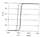
投影システム100で使われる光源1はパルス光源、たとえばパルス水銀ランプであってもさらによい。この場合、コールドミラー8の後ろのセンサ51は、パルスランプのパルス−プラトー率を決定するのに使われる。パルス60およびプラトー61を有するパルス水銀ランプの、光出力対時間のグラフの例が図5に示される。この光出力は水銀ランプの年齢と状態とに依存し、かつ駆動状況に依存する。計測された情報は、次に光源1の駆動部50へのフィードバックループで使われる。これは光源1のより容易な同期、および/または、必要であれば、パルス/プラトー率の調節を可能にする。
The
換言すると、コールドミラー8の後ろの光センサの使用によって、ACランプの場合には、光源1をモニタリングして、ランプを同期するためのフィードバックループで使われる情報を得ることができ、または、ACランプおよびDCランプの場合は出力を調節し、アークを安定化することができる。本発明による投影システム100の構成の具体的な利点は、光源1を水平に配置できることである。多くのタイプの光源1は、水平な配置で動作することが好ましい。傾いた配置ではアークの安定性と寿命とが低減される。下記の実施例において、瞳の充填が説明される。後者の実施例は、アパーチャ手段の中または近くの、異なる光源から出る光ビームの存在に関連する。ほとんどの用途の場合、アパーチャ自体の中で最適に調節が起るが、わずかな偏差、たとえばアパーチャ手段に隣接して調節手段を配置することで起る偏位によっても、許容できる結果を得ることができる。すなわち、アパーチャ手段の近くでということは、アパーチャ手段のアパーチャに隣接した領域においてということを意味し、そこではアパーチャ自体の中にあるのと本質的に等しい光ビームの特性が得られる。したがって、アパーチャの充填度を説明することは、アパーチャ手段の近くの対応する領域の充填度を説明することを含む。充填度ということは、入射光ビームの断面がどのように配置されるか、その表面面積がアパーチャの面積またはアパーチャ手段の近くの対応する領域面積に対してどれだけ大きいかを意味する。
In other words, by using a light sensor behind the cold mirror 8, in the case of an AC lamp, the
本発明はさらに第3の実施例に関し、その投影システムは、少なくとも2つの光源1と、集束システムと、アパーチャ3が配置されるところに焦点を有する集光レンズ2または1組の集光レンズと、空間光変調器4とも呼ばれる光バルブ4のセットと、投影レンズ5と、光バルブ4のセットの光束を鮮明に結像するために光路上のアパーチャ板3のアパーチャの下流に追加的に配置される、リレー光学系12とを含む。図1を再度参照する。ここで、光バルブ4のセットの照明を最適化できる。さらに、リレー光学系12の開口絞りが設けられてもよい。前の説明において、集束システムは典型的には第1のレンズアレイ6および第2のレンズアレイ7を含む。したがって、本実施例の投影システムにおいて、光ビームは少なくとも2つの光源1で生成され、光ビームはレンズアレイを用いて集束され、次いで光ビームが単一の照明ビームに集光されて、その形状がアパーチャ板3のアパーチャによって規定され、次いで光ビームは、照明ビームを光バルブのセットに最適に集
束するよう選択されるリレー光学系12を用いて、光バルブ4のセットに集束する。次に、光バルブ4のセットを駆動することによって拡張可能な投影画像が生成され、この拡張可能な画像が次に投影レンズ5を使って画面に投影される。本実施例の具体的な特徴は、集束する小レンズアレイシステムが、光路上でアパーチャの下流、すなわちアパーチャと光バルブ4のセットとの間に位置する追加的リレー光学系12と組合されることである。これにより、光バルブ4の照明が向上され、さらに、複数光源の小型投影システムにおけるコントラストおよび/または輝度を向上させる、新規な特徴を導入することができる。
The invention further relates to a third embodiment, in which the projection system comprises at least two
本実施例の投影システムは任意で、光源1の近くのUV/IRフィルタ、または代替として光源1に隣接するUVフィルタ9、および前の実施例による、集束システムの第1および第2のレンズアレイの間のコールドミラー8、調節可能な調光器10、拡散器11、および/またはハイコントラスト板14などをさらに含んでもよい。
The projection system of this embodiment is optional, the UV / IR filter near the
各光源1は平行な光束を投影する。これらの光源1はランプまたは発光装置のアレイであってもよい。使用ランプは投影システムで使われる従来のランプのどれでもよく、たとえば、限定されるものではないが、キセノンランプ、高圧水銀ランプ、ハロゲンランプまたはメタルハライドランプなどであってもよい。光源1の個数が増えると、単光源のシステムと比較して、各使用光源の出力が低減でき、または投影システムで得られる総出力が増大できる。光源1は発光装置のアレイであってもさらによく、すなわち1つの光源が1つの発光装置のアレイと対応してもよい。これらの装置は、たとえば発光ダイオードまたは有機発光ダイオードでもよい。後者はシステムをより小型化でき、これは顕著な利点となる。
Each
使用光源1の個数は2個でもよく、2×2のパターンで配置される4個の光源、2×3もしくは3×2のパターンで配置される6個の光源、または3×3のパターンで配置される9個の光源でもよい。他の個数の光源も使用できるが、瞳の最適な充填度が得られるので、2個、4個、6個または9個の光源の使用が好ましい。
The number of used
各光束は長方形の小レンズからなる古典的なレンズアレイシステムを通り、そこで第1のレンズアレイ6が、典型的には長方形ではないが好ましくは光源の長手の画像に合うよう最適化された形状を有する小レンズからなる第2のレンズアレイ7に、光源1、たとえばランプアークの像を作る。他の、完全には最適化されていない形状の小レンズを使うと、システムの効率はより低くなる。第2のレンズアレイ7は無限遠において第1のレンズアレイ6の像を投影する。第2のレンズアレイ7の真後ろにある集光レンズ2はこの像の焦点を合わせる。この焦点において均一で長方形な光のスポットがある。双方の光束は、双方の長方形の光のスポットが一致するように配置される。光源1およびレンズアレイ6,7によって形成される長方形の画像スポットは、たとえば理想的ではないレンズアレイ6,7および双方の光束の傾きに由来して、完全でなくてもよい。完全に長方形の光のスポットは、長方形のアパーチャ3を完全な長方形しか作れない位置に配置することによって生成され得る。
Each beam passes through a classical lens array system of rectangular lenslets, where the
空間光変調器アセンブリはどのような適切な光バルブまたは空間光変調器であってもよく、たとえばシングルチップまたは3チップの可変ミラーデバイス(DMD)エンジン、液晶表示(LCD)エンジン、または液晶オンシリコン(LCOS)エンジンであってもよい。これは、透過型または反射型の光変調器の一方でもよい。透過型装置は光ビームが装置を通過する際にビームを変調する。反射型装置は、装置内で光がミラーから反射する際に光を変調する。したがって、たとえば、デジタルミラーデバイスまたはデジタルミクロミラーデバイスとも呼ばれるDMD、反射型液晶(LCD)光バルブ、透過型液晶表示光バルブなど、異なるタイプの空間光変調器が使われてもよい。これらの構成要素は、前の実施例で記載されたものと同様である。 The spatial light modulator assembly may be any suitable light valve or spatial light modulator, such as a single-chip or three-chip variable mirror device (DMD) engine, a liquid crystal display (LCD) engine, or a liquid crystal on silicon. It may be an (LCOS) engine. This may be one of a transmissive or reflective light modulator. A transmissive device modulates the beam as it passes through the device. A reflective device modulates light as it reflects from a mirror within the device. Thus, different types of spatial light modulators may be used, such as DMD, also referred to as digital mirror device or digital micromirror device, reflective liquid crystal (LCD) light valve, transmissive liquid crystal display light valve. These components are similar to those described in the previous examples.
本発明における本実施例の特徴的な要素であるリレー光学系12は、アパーチャ板3のアパーチャから得られる長方形の光のスポットを、空間光変調器4を含む空間光変調器アセンブリに結像する。したがって、リレー光学系は光路上でアパーチャ板3のアパーチャの下流に配置される。リレー光学系は典型的には両側でテレセントリックであり、多くのレンズ、たとえば4個または6個のレンズを含む。この追加的光学システムは、たとえば異なるタイプのガラスを選択することにより材料が最適に選択され、かつ構造が最適化されることができるので、瞳の収差をほとんどなくすことができる。リレー光学系12の収差がレンズアレイシステムより小さいので、空間光変調器4の照明は、リレー光学系12がない場合よりもさらに鮮明な輪郭を有する。換言すると、レンズアレイの像を光バルブ4に直接投影する代わりにリレー光学系12が追加されると、光バルブ4の照明を向上させることができる。
The relay
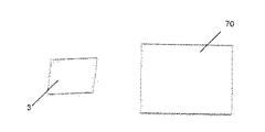
任意でDMDを光バルブとして使用する場合、実施例3は傾き手段を含む調節手段をもって調節される。このように、シャインプルフの法則にしたがって、すなわちリレー光学系12の光軸に対する光バルブの傾きを補正するために、アパーチャ3が傾けられる。アパーチャ3が傾けられると、その最適な形状は長方形ではなく、わずかに傾いて平行四辺形となる。これは図6および図7に示される。図6は、アパーチャ3が長方形の場合の、DMD70における平行四辺形の像を示す。図7は、アパーチャ3が光束に対して平行四辺形となる場合、すなわちアパーチャを傾ける場合の、DMD70における長方形の像を示す。したがって、このようにアパーチャを傾けることにより、シャインプルフ効果の補正が得られる。
If DMD is optionally used as a light valve, the third embodiment is adjusted by adjusting means including tilting means. Thus, the aperture 3 is tilted in accordance with Shine-Pluff's law, that is, to correct the tilt of the light valve with respect to the optical axis of the relay
したがって、本発明の本実施例によれば、光バルブの照明がより鮮明に輪郭を有する。これは光出力を向上させ、光バルブの熱負荷を低減する。これは、容易に遮光され得ない反射型光バルブには特に重要である。 Therefore, according to this embodiment of the present invention, the illumination of the light valve has a sharper contour. This improves the light output and reduces the heat load on the light valve. This is particularly important for reflective light valves that cannot be easily shielded from light.
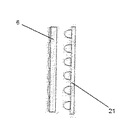
リレー光学系12とリレー光学系の開口絞り13を含む本発明の1から3のいずれかの実施例による、さらに他の実施例において、投影システムはさらにコントラストを向上させるための調節手段によって調節される一方、犠牲となる光出力を可能な限り低く抑えることができる。このようにして、たとえば光出力の半分のみを犠牲にすることにより、コントラストが2倍になる。これは、たとえば、図1に示されるように、リレー光学系の開口絞り13において挿入されるハイコントラスト板14のような、ブロック手段である調節手段を使うことによって可能である。このハイコントラスト板14は光をブロックするいかなる材料でできていてもよく、たとえば金属板でもよいが、それに限定されない。
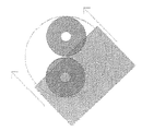
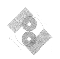
ハイコントラスト板14は、光バルブ4で入射最小角を有する光線がブロックされるように挿入される。これは、図8および図9に示される。図8では、充填された瞳が示される。瞳の中のある点を通過する光線はすべて同じ入射角で光バルブに当たる。点が瞳の左上部分にあればあるほど、その点を通過する光線の光バルブにおける入射角が大きい。図9において、瞳の右下部分をブロックするハイコントラスト板14が示され、この部分はすなわち光バルブ4で低い入射角を有する光線と対応する部分である。これらの光線をブロックすることによって画像のコントラストが強調され、光出力の犠牲は限定される。コントラストの強調は次の原理に基づく。光バルブ4で入射最小角を有する光線は、オフ状態の光バルブ4に反射した後に、投影レンズの入射瞳に最も接近して通る。光学表面には常にいくらかの散乱が存在するので、これらの光線は投影レンズの入射瞳を通過し、次に画面に到達する可能性が最も高く、光バルブがオフ状態にあるにもかかわらず光線が透過するので、そこでのコントラストを低減する。図9でハイコントラスト板14は真っ直ぐな端部を有して示されるが、湾曲した端部を有するハイコントラスト板14もさらに使用可能である。光出力/コントラスト率は、瞳の充填度に依存して、異なる端部を有するハイコントラスト板14を使って向上させることができる。
In yet another embodiment, according to any one of the embodiments of the present invention including a relay
The high contrast plate 14 is inserted so that the light bulb 4 blocks the light beam having the minimum incident angle. This is illustrated in FIGS. 8 and 9. In FIG. 8, a filled pupil is shown. All rays that pass through a point in the pupil strike the light valve at the same angle of incidence. The more the point is in the upper left part of the pupil, the greater the angle of incidence of light rays passing through that point at the light valve. In FIG. 9, a high-contrast plate 14 is shown that blocks the lower right part of the pupil, that is, the part corresponding to the light beam 4 having a low incidence angle. Blocking these rays enhances the contrast of the image and limits the sacrifice of light output. The contrast enhancement is based on the following principle. The light beam having the minimum incident angle at the light valve 4 is reflected by the light valve 4 in the off state and then passes closest to the entrance pupil of the projection lens. Since there is always some scattering on the optical surface, these rays are most likely to pass through the entrance pupil of the projection lens and then reach the screen, even though the light valve is off. , So that the contrast is reduced. Although the high contrast plate 14 is shown in FIG. 9 with straight edges, a high contrast plate 14 with curved edges can also be used. The light output / contrast ratio can be improved using a high contrast plate 14 with different edges, depending on the degree of pupil filling.
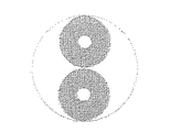
リレー光学系12およびリレー光学系の開口絞り13を含む、本発明の実施例1から3のいずれかの変形に関する他の実施例において説明すると、投影システムはさらに、光源1のアセンブリ、レンズアレイ、フィルタ、ミラー、およびフライアイなどの対応する光学要素を、リレー光学系12の光軸のまわりに回転させ得る回転手段である、調節手段で調節される。異なる光学要素はすべて同じ方法で調節される必要があることが理解されなければならない。この回転により、瞳の異なる位置で、異なる光源1の像を得ることができる。図10は、2つの光源1が光バルブで同じ平均入射角を有する場合、すなわち双方の光源1が同じコントラストを有する状態を示す。代替として、光源1および対応する光学要素がリレー光学系12の光軸のまわりを回転されてもよく、それにより一方の光源が光バルブ4における高い入射角と対応し、他方の光源は光バルブ4における低い入射角と対応する。この場合、一方の光源の像は瞳の左上部分の隅に位置し、他方の光源の像は瞳の右下部分の隅に位置する。次いで、投影システムのコントラストが変更されることができ、たとえば最も低い入射角に対応する光源を閉じることによってコントラストが得られるが、光出力の半分は犠牲となる。これは図11に示される。パネル14の挿入に基づくような基本的なコントラストエンハンサが存在する場合、パネル14の固定された位置に対して、光源1および対応する光学要素をリレー光学系12の光軸のまわりに回転させることによってコントラストは変更されるが、光出力の変更はより制限される。パネル14が瞳の半分をブロックすると、光源1および対応する光学要素を回転させることによって、光出力の量に影響することなく投影システムのコントラストが変更され得る。ランプの配向は設計段階において選択され、レンズアレイが適切に設計されることが必要である。
When described in another embodiment relating to any of the variations of
本発明のさらなる実施例において、前の実施例のいずれかによる投影システムが、さらに、調節可能な照明低減手段である調節要素を用いて調節され、生成される画像をより低い光度に調光できるように、すなわち、光出力が調節できるようになる。コントラストを変えることなく調光が実施できることは本発明の具体的な利点である。これは、プロジェクタ全体で均一な白黒レベルが要求される、マルチスクリーン用のプロジェクタで特に有益である。これは、調節可能な調光器10とも呼ばれる、調節可能な照明低減手段を用いることによって達成でき、調光器10は、使用光源1の光に対して非透過性の板を、各光源1について1つ含む。板は金属板であってもよいがそれに限定されない。調節可能な照明低減手段、すなわち調節可能な調光器10を使うことにより、図12に示されるように、非透過性板はレンズアレイのすぐ前または後に移動され、異なる光源1について左右対称に等しい面積部分をカバーする。これにより光バルブの平均入射角が変化せずに保たれ、コントラストが一定になる。対応する瞳の充填度は図13に示される。
In a further embodiment of the invention, the projection system according to any of the previous embodiments can be further adjusted using an adjustment element that is an adjustable illumination reduction means, and the resulting image can be dimmed to a lower intensity. That is, the light output can be adjusted. It is a specific advantage of the present invention that dimming can be performed without changing the contrast. This is particularly beneficial for multi-screen projectors where a uniform black and white level is required throughout the projector. This can be achieved by using adjustable lighting reduction means, also called
調節可能な調光器10についても同様に実施でき、図14に示されるように、対称な板はアパーチャ3において対称に配置される。
The same can be done for the
代替として、リレー光学系12を含む投影システムにおいて、1つの板がリレー光学系の開口絞り13に挿入されるが、それはハイコントラスト板に対しては直角である。このようにして、板を1つだけ使ってコントラストに影響を与えることなく光出力が調節される。これは図15に示される。このようにして光がブロックされ、それにより光出力が調節されるが、光バルブ4の平均入射角は変化しない。後者によって、コントラストは影響を受けないで保たれる。
Alternatively, in a projection system including
本発明による他の実施例において、投影システムはダイクロイックシフト光を制御するシステムであるブロック手段である調節手段をさらに備える。色プリズムにおける「ダイクロイックシフト光」の問題は、限定的ではないが、たとえば3チップデジタルミラーデバイスプロジェクタなどのカラー投影システムにおいて既知である。これは、3つの色、典型的には3原色である赤、緑および青を分離、合成するのに使われるダイクロイック被
膜によって引き起こされ、ダイクロイック被膜は典型的な角度依存、すなわち反射特性および透過特性が波長だけでなく入射角にも依存する性質を有する。1組の基本色に分かれる入射光束は、光バルブ4において、光バルブ4の傾き角度によって規定される一定の入射角をなし、再合成される射出光束は光バルブに直角なので、双方の光束はダイクロイック被膜において異なる入射角を有する。したがって、双方の光束に対するダイクロイック被膜の特性が異なる。このダイクロイックシフトのグラフは図16に示される。実線は入射角0°を有する光に対する典型的なダイクロイック被膜の透過を表し、点線は0°より大きい入射角を有する光に対する典型的なダイクロイック被膜の透過を表す。
In another embodiment according to the invention, the projection system further comprises adjusting means which are blocking means which are systems for controlling dichroic shifted light. The problem of “dichroic shifted light” in color prisms is known in color projection systems such as, but not limited to, 3-chip digital mirror device projectors. This is caused by the dichroic coating used to separate and synthesize three colors, typically the three primary colors red, green and blue, which are typical angular dependent, i.e. reflective and transmission characteristics. Has a property that depends not only on the wavelength but also on the incident angle. The incident light beam divided into one set of basic colors has a constant incident angle defined by the tilt angle of the light valve 4 in the light valve 4, and the re-combined exit light beam is perpendicular to the light valve, so both light beams are Different incidence angles in the dichroic coating. Therefore, the characteristics of the dichroic film for both light fluxes are different. A graph of this dichroic shift is shown in FIG. The solid line represents the transmission of a typical dichroic film for light having an incident angle of 0 °, and the dotted line represents the transmission of a typical dichroic film for light having an incident angle greater than 0 °.
分離プロセス中にダイクロイック被膜で反射する光が、再合成プロセス中にこの膜に反射せず、透過してしまうと問題が発生する。または補完的な状況において、分離プロセス中にダイクロイック被膜に透過された光が、再合成プロセス中にこの膜で反射される場合にも問題が発生する。光束のどの部分が、および入射光のどの波長がダイクロイックシフトを受けるかは、実験的または理論的に決定され得る。したがって、開口絞り13で光束の適切な部分をブロックする板、および/または光束の中で適切な波長をブロックする、リレー光学系12の好ましくはテレセントリックな部分にあるダイクロイックフィルタを使って、該当する光が選択的にブロックされることができる。図10および図11に示すように、光源1を回転させることによって、ダイクロイックシフトを受ける光の量はさらに低減されることができる。
Problems arise when light reflected by the dichroic coating during the separation process does not reflect through the film during the resynthesis process and passes through. Or, in a complementary situation, problems also arise when light transmitted to the dichroic coating during the separation process is reflected by this film during the resynthesis process. It can be determined experimentally or theoretically which part of the beam and which wavelength of the incident light undergoes the dichroic shift. Therefore, a plate that blocks the appropriate part of the light beam at the aperture stop 13 and / or a dichroic filter, preferably in the telecentric part of the relay
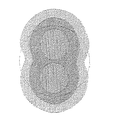
本発明の具体的実施例において、拡散器を含む調節手段を含む投影システムが説明されるが、システムはアパーチャがより均一に充填されることができるように調節される。アパーチャの充填は、図17および図18に示されるように、たとえば拡散ガラスなどの拡散器11を追加することによってさらに均一にされる。拡散器は典型的にはサンドブラストされたガラスでできている。投影システムに依存して、特別な被膜を施したガラスも、被膜が十分に耐熱性があれば使用できる。拡散器の強度を増すために透過性が低減されるので、投影システムの具体的な用途に依存して、光の十分な透過と十分な拡散との間に妥協点を見出す必要がある。図17は拡散器11のない投影システムにおけるデュアル光源システムの瞳を示し、図18は拡散器11を有する投影システムにおけるデュアル光源システムを示す。拡散器は長方形のアパーチャの後ろでアパーチャの近くに配置できるが、拡散器のガラスに付着した埃が光バルブの上に結像されないよう、長方形のアパーチャと全く同じ場所ではないことが好ましい。このように、拡散器11を使用することにより、瞳の充填度が向上される。より均一な瞳の充填が望ましく、有利なのは、本発明による実施例で説明される投影画像の制御をより容易にするからである。一方で、光出力は犠牲とならざるを得ない。上記の実施例で説明された追加的特徴により、投影画像の特性をさらに制御することが可能になる。コントラストおよび輝度は独立に調節されることができる。これは、異なるプロジェクタが同じ性質を有する必要がある、マルチスクリーンの分野では重要である。
In a specific embodiment of the invention, a projection system is described that includes adjusting means including a diffuser, but the system is adjusted so that the apertures can be more uniformly filled. The aperture filling is made more uniform by adding a
本発明のさらに他の利点は、双方の光源1を独立に制御できることのみならず、光源1の1つを交換できるよう、2個の別個のランプが使われることである。
Yet another advantage of the present invention is that not only can both
画像処理のための手段とメモリ部とを組合せると、投影システムはデジタル光処理システムを形成し、大きく、明るく、つなぎ目のない、コントラストの強いカラー画像を投影することができる。 Combining the means for image processing and the memory unit, the projection system forms a digital light processing system, which can project large, bright, seamless, high-contrast color images.
本発明による装置に関して、好ましい実施例、具体的な構造、構成および材料がここに説明されたが、形式および詳細における多様な変更と変形とが、本発明の範囲と精神とを逸脱することなくなされ得ることが理解される。 While preferred embodiments, specific structures, configurations and materials have been described herein for the apparatus according to the present invention, various changes and modifications in form and detail may be made without departing from the scope and spirit of the invention. It is understood that this can be done.
1 光源、2 集光レンズ、3 アパーチャ、4 光バルブ、5 投影レンズ、6 第1のレンズアレイ、7 第2のレンズアレイ、8 コールドミラー、9 UVフィルタ、10 調光器、11 拡散器、12 リレー光学系、13 開口絞り、14 ハイコントラスト板、100 投影システム。
DESCRIPTION OF
Claims (23)
光ビームを生成するために少なくとも2つの光源の各々を駆動するステップと、
前記各光源から前記光ビームを単一の照明ビームに集光するステップと、
前記単一の照明ビームで光バルブアセンブリを照らすステップとを含み、さらに、
前記方法は、前記単一の照明ビームで光バルブアセンブリを照らす前に、
少なくとも1つの前記光源(1)の前記光ビームの断面をアパーチャ手段の中または近くで調節するステップを含む、方法。 A method using a multiple light source projection system, the method comprising:
Driving each of the at least two light sources to generate a light beam;
Condensing the light beam from each light source into a single illumination beam;
Illuminating a light valve assembly with the single illumination beam; and
Before the method illuminates the light valve assembly with the single illumination beam,
Adjusting the cross-section of the light beam of at least one light source (1) in or near aperture means.
Applications Claiming Priority (1)
| Application Number | Priority Date | Filing Date | Title |
|---|---|---|---|
| US53759404P | 2004-01-20 | 2004-01-20 |
Publications (2)
| Publication Number | Publication Date |
|---|---|
| JP2005234551A true JP2005234551A (en) | 2005-09-02 |
| JP2005234551A5 JP2005234551A5 (en) | 2008-03-06 |
Family
ID=34633017
Family Applications (1)
| Application Number | Title | Priority Date | Filing Date |
|---|---|---|---|
| JP2005011715A Pending JP2005234551A (en) | 2004-01-20 | 2005-01-19 | Projection system and method for using projection system using multiple light sources |
Country Status (3)
| Country | Link |
|---|---|
| US (1) | US7284868B2 (en) |
| EP (1) | EP1558042A3 (en) |
| JP (1) | JP2005234551A (en) |
Cited By (3)
| Publication number | Priority date | Publication date | Assignee | Title |
|---|---|---|---|---|
| US7466499B2 (en) | 2005-10-19 | 2008-12-16 | Seiko Epson Corporation | Projector |
| JP2016114925A (en) * | 2014-12-15 | 2016-06-23 | テスト リサーチ, インク. | Optical system and image compensation method for optical device |
| JP2016173450A (en) * | 2015-03-17 | 2016-09-29 | セイコーエプソン株式会社 | Projector and method for controlling projector |
Families Citing this family (10)
| Publication number | Priority date | Publication date | Assignee | Title |
|---|---|---|---|---|
| US7434942B2 (en) * | 2004-04-29 | 2008-10-14 | Pate Michael A | Projection system |
| US7230768B2 (en) * | 2005-04-27 | 2007-06-12 | Christie Digital Systems Inc. | Ultra-bright light engine for projection displays |
| GB0511692D0 (en) * | 2005-06-08 | 2005-07-13 | Digital Projection Ltd | Heat transfer apparatus |
| US7706420B2 (en) * | 2006-09-05 | 2010-04-27 | Corning Incorporated | Optical power modulation at high frequency |
| RU2455671C2 (en) * | 2010-09-01 | 2012-07-10 | Закрытое акционерное общество "МНИТИ", ЗАО "МНИТИ" | Projecting device for displaying video on composite translucent screen |
| JP2013148625A (en) * | 2012-01-17 | 2013-08-01 | Panasonic Corp | Projection type image display device |
| US11885738B1 (en) | 2013-01-22 | 2024-01-30 | J.A. Woollam Co., Inc. | Reflectometer, spectrophotometer, ellipsometer or polarimeter system including sample imaging system that simultaneously meet the scheimpflug condition and overcomes keystone error |
| US9971233B2 (en) * | 2015-03-17 | 2018-05-15 | Seiko Epson Corporation | Projector and method of controlling projector |
| CN114008516A (en) | 2018-11-19 | 2022-02-01 | 飞行安全国际公司 | Method and apparatus for remapping pixel locations |
| CN113424103B (en) | 2018-11-20 | 2023-07-18 | 飞行安全国际公司 | Rear projection simulator with free form folding mirror |
Citations (14)
| Publication number | Priority date | Publication date | Assignee | Title |
|---|---|---|---|---|
| JPS59111136A (en) * | 1982-12-16 | 1984-06-27 | Wakomu Seisakusho:Kk | Light source device for projection |
| JPH0836180A (en) * | 1994-05-16 | 1996-02-06 | Matsushita Electric Ind Co Ltd | Projection type display device |
| JPH09133974A (en) * | 1995-11-10 | 1997-05-20 | Hitachi Ltd | Liquid crystal projector |
| WO1998009113A1 (en) * | 1996-08-26 | 1998-03-05 | Seiko Epson Corporation | Illuminating apparatus and projection display |
| JPH10509808A (en) * | 1994-10-27 | 1998-09-22 | マサチユセツツ・インスチチユート・オブ・テクノロジー | Illumination system for display panel |
| JP2001013604A (en) * | 1999-07-02 | 2001-01-19 | Matsushita Electric Ind Co Ltd | Projection type picture display device of light source double-light system being suitable for time-division driving |
| JP2001042433A (en) * | 1999-06-08 | 2001-02-16 | Karlheinz Strobl | High performance optical engine system, its component and its production |
| JP2001222002A (en) * | 2000-02-10 | 2001-08-17 | Sony Corp | Liquid crystal projector device |
| JP2002090705A (en) * | 2000-09-12 | 2002-03-27 | Seiko Epson Corp | Projector, and method for adjusting light quantity in the same |
| US20020126264A1 (en) * | 2001-03-06 | 2002-09-12 | Dewald D. Scott | High contrast projection |
| WO2002084339A2 (en) * | 2001-04-13 | 2002-10-24 | Koninklijke Philips Electronics N.V. | Projection display system using two lamp sources |
| WO2002088841A1 (en) * | 2001-04-25 | 2002-11-07 | Matsushita Electric Industrial Co., Ltd. | Projection display device |
| JP2003315733A (en) * | 2002-04-25 | 2003-11-06 | Mitsubishi Electric Corp | Image display device |
| JP2003322822A (en) * | 2002-04-30 | 2003-11-14 | Mitsubishi Electric Corp | Picture display device |
Family Cites Families (8)
| Publication number | Priority date | Publication date | Assignee | Title |
|---|---|---|---|---|
| US3693515A (en) * | 1971-04-30 | 1972-09-26 | Vari Typer Corp | Optical reflector system |
| US5597223A (en) * | 1993-12-27 | 1997-01-28 | Kabushiki Kaisha Toshiba | Display apparatus |
| US5924783A (en) * | 1997-07-24 | 1999-07-20 | Raychem Corporation | System for controlling contrast in projection displays |
| US6666558B1 (en) * | 1999-07-02 | 2003-12-23 | Matsushita Electric Industrial Co., Ltd. | Projection image display |
| US7131736B2 (en) * | 2002-05-17 | 2006-11-07 | Bierhuizen Serge J A | Efficient illumination systems for reduced étendue color video projection systems |
| JP3989412B2 (en) * | 2002-10-21 | 2007-10-10 | オリンパス株式会社 | Illumination device and image projection device |
| US20040150794A1 (en) * | 2003-01-30 | 2004-08-05 | Eastman Kodak Company | Projector with camcorder defeat |
| JP2005183470A (en) * | 2003-12-16 | 2005-07-07 | Olympus Corp | Lighting system and image projection equipment using the same |
-
2005
- 2005-01-17 EP EP05000797A patent/EP1558042A3/en not_active Ceased
- 2005-01-19 US US11/037,008 patent/US7284868B2/en active Active
- 2005-01-19 JP JP2005011715A patent/JP2005234551A/en active Pending
Patent Citations (14)
| Publication number | Priority date | Publication date | Assignee | Title |
|---|---|---|---|---|
| JPS59111136A (en) * | 1982-12-16 | 1984-06-27 | Wakomu Seisakusho:Kk | Light source device for projection |
| JPH0836180A (en) * | 1994-05-16 | 1996-02-06 | Matsushita Electric Ind Co Ltd | Projection type display device |
| JPH10509808A (en) * | 1994-10-27 | 1998-09-22 | マサチユセツツ・インスチチユート・オブ・テクノロジー | Illumination system for display panel |
| JPH09133974A (en) * | 1995-11-10 | 1997-05-20 | Hitachi Ltd | Liquid crystal projector |
| WO1998009113A1 (en) * | 1996-08-26 | 1998-03-05 | Seiko Epson Corporation | Illuminating apparatus and projection display |
| JP2001042433A (en) * | 1999-06-08 | 2001-02-16 | Karlheinz Strobl | High performance optical engine system, its component and its production |
| JP2001013604A (en) * | 1999-07-02 | 2001-01-19 | Matsushita Electric Ind Co Ltd | Projection type picture display device of light source double-light system being suitable for time-division driving |
| JP2001222002A (en) * | 2000-02-10 | 2001-08-17 | Sony Corp | Liquid crystal projector device |
| JP2002090705A (en) * | 2000-09-12 | 2002-03-27 | Seiko Epson Corp | Projector, and method for adjusting light quantity in the same |
| US20020126264A1 (en) * | 2001-03-06 | 2002-09-12 | Dewald D. Scott | High contrast projection |
| WO2002084339A2 (en) * | 2001-04-13 | 2002-10-24 | Koninklijke Philips Electronics N.V. | Projection display system using two lamp sources |
| WO2002088841A1 (en) * | 2001-04-25 | 2002-11-07 | Matsushita Electric Industrial Co., Ltd. | Projection display device |
| JP2003315733A (en) * | 2002-04-25 | 2003-11-06 | Mitsubishi Electric Corp | Image display device |
| JP2003322822A (en) * | 2002-04-30 | 2003-11-14 | Mitsubishi Electric Corp | Picture display device |
Cited By (3)
| Publication number | Priority date | Publication date | Assignee | Title |
|---|---|---|---|---|
| US7466499B2 (en) | 2005-10-19 | 2008-12-16 | Seiko Epson Corporation | Projector |
| JP2016114925A (en) * | 2014-12-15 | 2016-06-23 | テスト リサーチ, インク. | Optical system and image compensation method for optical device |
| JP2016173450A (en) * | 2015-03-17 | 2016-09-29 | セイコーエプソン株式会社 | Projector and method for controlling projector |
Also Published As
| Publication number | Publication date |
|---|---|
| EP1558042A3 (en) | 2006-06-07 |
| US7284868B2 (en) | 2007-10-23 |
| US20050157275A1 (en) | 2005-07-21 |
| EP1558042A2 (en) | 2005-07-27 |
Similar Documents
| Publication | Publication Date | Title |
|---|---|---|
| US7284868B2 (en) | Compact projection systems using multiple light sources | |
| JP5156338B2 (en) | LIGHTING DEVICE AND PROJECTION VIDEO DISPLAY DEVICE USING THE SAME | |
| TWI238920B (en) | Lighting, and projection type display and driving method of the display | |
| US20020048172A1 (en) | Lens element and illumination optical apparatus and projection display apparatus | |
| WO1998029773A1 (en) | Image display | |
| JP2002023106A (en) | Illumination optical system and projector provided with the same | |
| JPWO2002101457A1 (en) | Illumination device and projection type video display device | |
| KR20060089502A (en) | Light tunnel and projection apparatus having the same | |
| JPH11149061A (en) | Light source device and illumination device | |
| JPH06265887A (en) | Projection type display device | |
| US8308305B2 (en) | Projector with optical filter reducing internal multiple reflections | |
| WO2002088841A1 (en) | Projection display device | |
| JP2008090018A (en) | Image display device | |
| JP2002072361A (en) | Lighting optical system, optical device having the same lighting optical system, and image processor | |
| JP2007293033A (en) | Image projector | |
| JP5625932B2 (en) | Projection display | |
| JP2007322923A (en) | Optical device and projection type display apparatus | |
| EP1627527B1 (en) | Illumination system for videoprojector utilizing one or more led diodes matrices | |
| JP2004219983A (en) | Image display device | |
| JP3510849B2 (en) | Projection type video display | |
| JP2010286542A (en) | Illuminator and projector | |
| JP4534602B2 (en) | Projection-type image display device | |
| JP4189262B2 (en) | Multiple lamp device for optical device | |
| WO2023037729A1 (en) | Projection image display device | |
| JP2010091772A (en) | Projection type display device |
Legal Events
| Date | Code | Title | Description |
|---|---|---|---|
| A521 | Written amendment |
Free format text: JAPANESE INTERMEDIATE CODE: A523 Effective date: 20080118 |
|
| A621 | Written request for application examination |
Free format text: JAPANESE INTERMEDIATE CODE: A621 Effective date: 20080118 |
|
| A977 | Report on retrieval |
Free format text: JAPANESE INTERMEDIATE CODE: A971007 Effective date: 20090619 |
|
| A131 | Notification of reasons for refusal |
Free format text: JAPANESE INTERMEDIATE CODE: A131 Effective date: 20090630 |
|
| A02 | Decision of refusal |
Free format text: JAPANESE INTERMEDIATE CODE: A02 Effective date: 20091201 |