JP2009191663A - Fuel injection control device for internal combustion engine - Google Patents
Fuel injection control device for internal combustion engine Download PDFInfo
- Publication number
- JP2009191663A JP2009191663A JP2008031156A JP2008031156A JP2009191663A JP 2009191663 A JP2009191663 A JP 2009191663A JP 2008031156 A JP2008031156 A JP 2008031156A JP 2008031156 A JP2008031156 A JP 2008031156A JP 2009191663 A JP2009191663 A JP 2009191663A
- Authority
- JP
- Japan
- Prior art keywords
- cylinder
- fuel
- injection
- mode
- port
- Prior art date
- Legal status (The legal status is an assumption and is not a legal conclusion. Google has not performed a legal analysis and makes no representation as to the accuracy of the status listed.)
- Pending
Links
Images
Classifications
-
- F—MECHANICAL ENGINEERING; LIGHTING; HEATING; WEAPONS; BLASTING
- F02—COMBUSTION ENGINES; HOT-GAS OR COMBUSTION-PRODUCT ENGINE PLANTS
- F02D—CONTROLLING COMBUSTION ENGINES
- F02D41/00—Electrical control of supply of combustible mixture or its constituents
- F02D41/30—Controlling fuel injection
- F02D41/3094—Controlling fuel injection the fuel injection being effected by at least two different injectors, e.g. one in the intake manifold and one in the cylinder
Landscapes
- Engineering & Computer Science (AREA)
- Chemical & Material Sciences (AREA)
- Combustion & Propulsion (AREA)
- Mechanical Engineering (AREA)
- General Engineering & Computer Science (AREA)
- Combustion Methods Of Internal-Combustion Engines (AREA)
- Electrical Control Of Air Or Fuel Supplied To Internal-Combustion Engine (AREA)
- Combined Controls Of Internal Combustion Engines (AREA)
Abstract
【課題】燃料の噴射モードの切換タイミングを適切に制御することにより、内燃機関に要求される燃料量を気筒ごとに過不足なく供給することができ、それにより、良好なドライバビリティを確保することができる内燃機関の燃料噴射制御装置を提供する。
【解決手段】この燃料噴射制御装置1は、検出された内燃機関3の回転数NEおよび負荷APに応じて、内燃機関3に供給すべき要求燃料量GCYLを算出し、この要求燃料量GCYLに応じて、噴射モードを、筒内燃料噴射弁6のみから燃料を噴射する筒内噴射モードと、筒内燃料噴射弁6およびポート燃料噴射弁8の双方から燃料を噴射する筒内・ポート噴射モードの一方に決定する。また、検出されたクランク角が所定のクランク角度区間にあると判定された気筒3aに対して、噴射モード決定手段による決定に応じた噴射モードの切換を禁止する。
【選択図】図7By appropriately controlling the switching timing of the fuel injection mode, the amount of fuel required for an internal combustion engine can be supplied to each cylinder without excess or deficiency, thereby ensuring good drivability. Provided is a fuel injection control device for an internal combustion engine.
The fuel injection control device calculates a required fuel amount GCYL to be supplied to the internal combustion engine 3 according to the detected rotational speed NE and load AP of the internal combustion engine 3, and sets the required fuel amount GCYL to the required fuel amount GCYL. Accordingly, the injection mode includes an in-cylinder injection mode in which fuel is injected only from the in-cylinder fuel injection valve 6, and an in-cylinder / port injection mode in which fuel is injected from both the in-cylinder fuel injection valve 6 and the port fuel injection valve 8. Decide on one of these. Further, switching of the injection mode according to the determination by the injection mode determining means is prohibited for the cylinder 3a determined that the detected crank angle is in the predetermined crank angle section.
[Selection] Figure 7
Description
本発明は、気筒内に燃料を噴射する筒内燃料噴射弁と、吸気ポートに燃料を噴射するポート燃料噴射弁を有する内燃機関の燃料噴射制御装置に関する。 The present invention relates to a fuel injection control device for an internal combustion engine having an in-cylinder fuel injection valve for injecting fuel into a cylinder and a port fuel injection valve for injecting fuel into an intake port.
従来、この種の内燃機関の燃料噴射制御装置として、例えば特許文献1に開示されたものが知られている。この内燃機関では、高回転高負荷時に均質燃焼が行われ、低回転低負荷時に成層燃焼が行われる。成層燃焼時には、圧縮行程中に、筒内燃料噴射弁から燃焼室に燃料を噴射する。一方、均質燃焼時には、吸気行程中に、ポート燃料噴射弁から吸気ポートに燃料を噴射する。なお、均質燃焼時には、圧縮行程中に、筒内燃料噴射弁から極少量の燃料が補助的に噴射される。それにより、燃料の気化による冷却効果によって、筒内燃料噴射弁の先端部の過熱を防止し、過熱による噴孔部へのデポジットの堆積などを抑制するようにしている。
Conventionally, as a fuel injection control device for this type of internal combustion engine, for example, one disclosed in
以上のように、従来の燃料噴射制御装置では、ポート燃料噴射弁による吸気行程中のポート噴射と筒内燃料噴射弁による圧縮行程中の筒内噴射の切換が、内燃機関の燃焼モードの切換に連動して行われる。このため、燃焼モードの切換タイミングによっては、一部の気筒に対して、内燃機関に要求される燃料量を適正に供給できないことがある。例えば、成層燃焼への切換が圧縮行程中に行われた気筒では、吸気行程において、均質燃焼用のポート噴射が行われた後に、圧縮行程において成層燃焼用の筒内噴射がさらに行われることがあり、その場合には、燃料の供給量が過剰になる。これとは逆に、均質燃焼への切換が圧縮行程中に行われた気筒では、吸気行程でのポート噴射が間に合わず、圧縮行程での筒内噴射も行われないことから、燃料の供給量が不足することがある。これらの場合、それに伴ってトルクの変動が大きくなり、トルクショックが生じることなどによって、ドライバビリティが低下してしまう。 As described above, in the conventional fuel injection control device, the switching between the port injection during the intake stroke by the port fuel injection valve and the in-cylinder injection during the compression stroke by the in-cylinder fuel injection valve is the switching of the combustion mode of the internal combustion engine. It is done in conjunction. For this reason, depending on the switching timing of the combustion mode, the fuel amount required for the internal combustion engine may not be properly supplied to some cylinders. For example, in a cylinder in which switching to stratified combustion is performed during the compression stroke, in-cylinder injection for stratified combustion is further performed in the compression stroke after port injection for homogeneous combustion is performed in the intake stroke. In this case, the amount of fuel supplied becomes excessive. On the other hand, in a cylinder in which switching to homogeneous combustion is performed during the compression stroke, port injection in the intake stroke is not in time, and in-cylinder injection in the compression stroke is not performed, so the amount of fuel supply May be insufficient. In these cases, the fluctuation of the torque is increased accordingly, and the drivability is lowered due to the occurrence of a torque shock.
本発明は、以上のような課題を解決するためになされたものであり、燃料の噴射モードの切換タイミングを適切に制御することにより、内燃機関に要求される燃料量を気筒ごとに過不足なく供給することができ、それにより、良好なドライバビリティを確保することができる内燃機関の燃料噴射制御装置を提供することを目的とする。 The present invention has been made to solve the above-described problems. By appropriately controlling the switching timing of the fuel injection mode, the amount of fuel required for the internal combustion engine can be reduced for each cylinder. It is an object of the present invention to provide a fuel injection control device for an internal combustion engine that can be supplied, thereby ensuring good drivability.
上記の目的を達成するため、本願の請求項1に係る発明は、気筒3a内に燃料を噴射する筒内燃料噴射弁6と、吸気ポート3fに燃料を噴射するポート燃料噴射弁8を有する内燃機関3の燃料噴射制御装置1であって、内燃機関3の回転数(実施形態における(以下、本項において同じ)エンジン回転数NE)を検出する回転数検出手段(クランク角センサ21)と、内燃機関3の負荷(アクセル開度AP)を検出する負荷検出手段(アクセル開度センサ22)と、検出された内燃機関3の回転数および負荷に応じて、内燃機関3に供給すべき要求燃料量GCYLを算出する要求燃料量算出手段(ECU2、図6のステップ21)と、算出された要求燃料量GCYLに応じて、噴射モードを、筒内燃料噴射弁6のみから燃料を噴射する筒内噴射モードと、筒内燃料噴射弁6およびポート燃料噴射弁8の双方から燃料を噴射する筒内・ポート噴射モードの一方に決定する噴射モード決定手段(ECU2、図7のステップ37〜40)と、内燃機関3のクランク角を検出するクランク角検出手段(クランク角センサ21)と、検出されたクランク角が、筒内燃料噴射弁6およびポート燃料噴射弁8による燃料の噴射期間(排気行程開始時から吸気行程終了時)を含む所定のクランク角度区間にあるか否かを、気筒ごとに判定する判定手段(ECU2、図7のステップ41)と、検出されたクランク角が所定のクランク角度区間にあると判定された気筒3aに対して、噴射モード決定手段による決定に応じた噴射モードの切換を禁止する噴射モード切換禁止手段(ECU2、図7のステップ43)と、を備えることを特徴とする。
In order to achieve the above object, the invention according to
この内燃機関の燃料噴射制御装置によれば、燃焼モードが、気筒内に燃料を噴射する筒内燃料噴射弁による筒内噴射のみを実行する筒内噴射モードと、筒内噴射および吸気ポートに燃料を噴射するポート燃料噴射弁によるポート噴射の双方を実行する筒内・ポート噴射モードに切り換えられる。この噴射モードの切換の決定は、検出された内燃機関の回転数および負荷に応じて算出された要求燃料量に応じ、噴射モード決定手段によって行われる。また、検出した内燃機関のクランク角が、筒内燃料噴射弁およびポート燃料噴射弁による燃料の噴射期間を含む所定のクランク角度区間にあるか否かを、気筒ごとに判定する。そして、クランク角が所定のクランク角度区間にあると判定された気筒に対して、噴射モードの切換を禁止する。以上のように、噴射モード決定手段によって噴射モードの切換が決定されても、クランク角が筒内噴射または筒内・ポート噴射による燃料の噴射期間を含む所定のクランク角度区間にあるときには、実際にはその気筒の噴射モードは、切り換えられることなく、維持される。これにより、噴射モードの切換タイミングを気筒ごとに適切に制御でき、内燃機関に要求される燃料量を気筒ごとに過不足なく供給できる結果、良好なドライバビリティを確保することができる。 According to this fuel injection control device for an internal combustion engine, the combustion mode includes in-cylinder injection mode in which only in-cylinder injection is performed by the in-cylinder fuel injection valve that injects fuel into the cylinder, and in-cylinder injection and fuel in the intake port Is switched to the in-cylinder / port injection mode in which both port injection is performed by the port fuel injection valve for injecting fuel. The injection mode switching is determined by the injection mode determining means according to the required fuel amount calculated according to the detected rotational speed and load of the internal combustion engine. Further, it is determined for each cylinder whether or not the detected crank angle of the internal combustion engine is in a predetermined crank angle section including a fuel injection period by the in-cylinder fuel injection valve and the port fuel injection valve. Then, switching of the injection mode is prohibited for the cylinder determined to have the crank angle in the predetermined crank angle section. As described above, even if the switching of the injection mode is determined by the injection mode determining means, when the crank angle is in the predetermined crank angle section including the fuel injection period by in-cylinder injection or in-cylinder / port injection, The injection mode of the cylinder is maintained without being switched. As a result, the switching timing of the injection mode can be appropriately controlled for each cylinder, and the amount of fuel required for the internal combustion engine can be supplied without excess or deficiency for each cylinder. As a result, good drivability can be ensured.
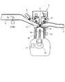
以下、図面を参照しながら、本発明の好ましい実施形態について説明する。図1は、本実施形態による燃料噴射制御装置1を適用した内燃機関3を概略的に示している。内燃機関(以下「エンジン」という)3は、車両(図示せず)に搭載された、例えば直列4気筒の4サイクルガソリンエンジンである。
Hereinafter, preferred embodiments of the present invention will be described with reference to the drawings. FIG. 1 schematically shows an
エンジン3のシリンダヘッド3cには、吸気管4および排気管5が接続されるとともに、気筒3aごとに、筒内燃料噴射弁6および点火プラグ7(図2参照)が、燃焼室3dに臨むように取り付けられている(いずれも1つのみ図示)。この筒内燃料噴射弁6は、第1燃料ポンプ(図示せず)で高圧に昇圧された燃料を、燃焼室3d内の点火プラグ7の付近に噴射する。また、筒内燃料噴射弁6の開弁時間および開弁時期と点火プラグ7の点火時期は、燃料噴射制御装置1の後述するECU2によって制御される。
An
エンジン3には、クランク角センサ21が設けられている。クランク角センサ21は、マグネットロータおよびMREピックアップ(いずれも図示せず)で構成されており、クランクシャフト3eの回転に伴い、パルス信号であるCRK信号およびTDC信号(図10参照)をECU2に出力する。
The
CRK信号は、所定のクランク角(例えば30゜)ごとに出力される。ECU2は、CRK信号に基づき、エンジン3の回転数(以下「エンジン回転数」という)NEを算出する。また、TDC信号は、いずれかの気筒3aにおいて、ピストン3bが吸気行程開始時のTDC(上死点)付近の所定のクランク角度位置にあることを表す信号であり、本実施形態のように4気筒の場合には、クランク角180゜ごとに出力される。
The CRK signal is output every predetermined crank angle (for example, 30 °). The ECU 2 calculates the engine speed (hereinafter referred to as “engine speed”) NE of the
また、CRK信号およびTDC信号には、所定のクランク角度位置に、気筒3aを判別するためのパルス信号である気筒判別信号が含まれている。ECU2は、これらの3つの信号に基づいて、燃料噴射制御用のクランク角ステージFISTG#nを気筒3aごとに算出する。このクランク角ステージFISTG#nは、各気筒3aにおいて、所定のクランク角(例えばTDC信号の発生クランク角)を基準として、1燃焼サイクルに相当する720°のクランク角度を30゜ごとに区分し、順にステージ番号0〜23を割り当てたものである。なお、このFISTG#nの添え字「#n」は、そのパラメータが気筒3aごとに設定されることを表しており(n=1〜4)、このことは該当する他のパラメータについても同様である。
Further, the CRK signal and the TDC signal include a cylinder discrimination signal that is a pulse signal for discriminating the cylinder 3a at a predetermined crank angle position. The
吸気管4の吸気マニホルドには、ポート燃料噴射弁8が、気筒3aごとに、吸気ポート3fに臨むように設けられている。ポート燃料噴射弁8は、第2燃料ポンプ(図示せず)で昇圧された燃料を吸気ポート3fに噴射する。ポート燃料噴射弁8の開弁時間および開弁時期は、ECU2によって制御される。
A port
また、吸気管4には、スロットル弁機構9が設けられている。スロットル弁機構9は、吸気管4内に配置された回動自在のスロットル弁9aと、これを駆動するTHアクチュエータ9bを有している。THアクチュエータ9bは、モータとギヤ機構(いずれも図示せず)を組み合わせたものであり、ECU2からの制御信号で駆動され、それにより、スロットル弁9aの開度が変化することで、吸入空気量が制御される。
The
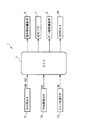
ECU2にはさらに、アクセル開度センサ22から、アクセルペダルの操作量(以下「アクセル開度」という)APを表す検出信号が、エンジン水温センサ23から、エンジン3の本体内を循環する冷却水の温度(以下「エンジン水温」という)TWを表す検出信号が、それぞれ出力される。
The
ECU2は、I/Oインターフェース、CPU、RAMおよびROMなどから成るマイクロコンピュータで構成されている。ECU2は、前述したセンサ21〜23からの検出信号に応じて、エンジン3の運転状態を判別し、エンジン3の燃焼モードを決定する。また、決定した燃焼モードに従って、筒内燃料噴射弁6およびポート燃料噴射弁8を制御する燃料噴射制御や、スロットル弁機構9を制御する吸入空気量制御などを実行する。
The ECU 2 is composed of a microcomputer including an I / O interface, CPU, RAM, ROM, and the like. The ECU 2 determines the operating state of the
なお、本実施形態では、ECU2が、要求燃料量算出手段、噴射モード決定手段、判定手段および噴射モード切換禁止手段に相当する。
In the present embodiment, the
上記の燃焼モードは、次の成層自己着火燃焼モード、成層火炎伝播燃焼モード、および均質火炎伝播燃焼モードで構成されている。 The combustion mode is composed of the following stratified self-ignition combustion mode, stratified flame propagation combustion mode, and homogeneous flame propagation combustion mode.
(1)成層自己着火燃焼モード
圧縮行程中に筒内燃料噴射弁6から燃料を噴射することにより、成層混合気を生成し、これを自己着火燃焼させる燃焼モード
(2)成層火炎伝播燃焼モード
圧縮行程中に筒内燃料噴射弁6から燃料を噴射することにより、成層混合気を生成し、これを点火プラグ7による火花点火により火炎伝播燃焼させる燃焼モード
(3)均質燃焼モード
吸気行程中に筒内燃料噴射弁6から燃料を噴射することにより、均質混合気を生成し、これを火花点火により火炎伝播燃焼させる燃焼モード。また、エンジン3に要求される要求燃料量GCYLに対して、筒内燃料噴射弁6による筒内噴射だけでは燃料量が不足する場合には、これを補うために、排気行程の終期から吸気行程にかけて、ポート燃料噴射弁8によるポート噴射が併せて実行される。
(1) Stratified self-ignition combustion mode Combustion mode in which stratified mixture is generated by injecting fuel from the in-cylinder
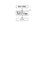
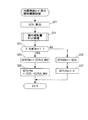
また、上記の燃焼モードは、次のようにして決定される。まず、図3の要求トルク算出処理により、エンジン回転数NEおよびアクセル開度APに応じ、所定のマップ(図示せず)を検索することによって、エンジン3に要求される要求トルクPMCMDを算出する(ステップ1)。
The combustion mode is determined as follows. First, the required torque PMCMD required for the
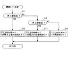
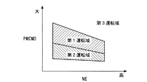
次に、図4の燃焼モード決定処理により、エンジン回転数NEと算出した要求トルクPMCMDに応じて、燃焼モードを決定する。まず、そのステップ11では、図5のマップを参照することによって、エンジン回転数NEおよび要求トルクPMCMDが、低中回転・中負荷域に相当する第1運転域にあるか否かを判別する。この判別結果がYESのときには、燃焼モードを成層自己着火燃焼モードに決定するとともに、燃焼モード値STS_BURNCMDを「1」にセットする(ステップ12)。
Next, the combustion mode is determined according to the engine speed NE and the calculated required torque PMCMD by the combustion mode determination process of FIG. First, in
ステップ11の判別結果がNOのときには、エンジン回転数NEおよび要求トルクPMCMDが、低中回転・低負荷域に相当する第2運転域にあるか否かを判別する(ステップ13)。この判別結果がYESのときには、燃焼モードを成層火炎伝播燃焼モードに決定するとともに、燃焼モード値STS_BURNCMDを「2」にセットする(ステップ14)。
When the determination result in
ステップ13の判別結果がNOで、エンジン回転数NEおよび要求トルクPMCMDが第1および第2運転域以外の第3運転域にあるときには、燃焼モードを均質火炎伝播燃焼モードに決定するとともに、燃焼モード値STS_BURNCMDを「3」にセットする(ステップ15)、本処理を終了する。
When the determination result of
次に、上記の燃焼モードのうち、均質燃焼モード用の燃料噴射制御処理を、図6を参照しながら説明する。本処理は、CRK信号が発生するごとに、これに同期して実行される。 Next, fuel injection control processing for the homogeneous combustion mode among the above combustion modes will be described with reference to FIG. This process is executed in synchronism with the generation of the CRK signal.
まず、ステップ21では、エンジン回転数NEおよび要求トルクPMCMDに応じ、所定のマップ(図示せず)を検索することによって、エンジン3の各気筒3aに要求される要求燃料量GCYLを算出する。
First, in
次に、筒内噴射量GCYLDのリミット処理を実行する(ステップ22)。このリミット処理は、筒内噴射量GCYLDの最大値を算出するとともに、噴射モードを、筒内燃料噴射弁6による筒内噴射のみを実行する筒内噴射モード(以下「DIモード」という)と、筒内噴射とポート燃料噴射弁8によるポート噴射を併用する筒内・ポート噴射モード(以下「DI・PIモード」という)に、気筒3aごとに切り換えて設定するものである。
Next, limit processing of the in-cylinder injection amount GCYLD is executed (step 22). This limit process calculates the maximum value of the in-cylinder injection amount GCYLD, and the injection mode is an in-cylinder injection mode in which only in-cylinder injection by the in-cylinder
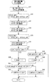
図7はそのサブルーチンを示している。まず、ステップ31において、エンジン回転数NEおよびエンジン水温TWに応じ、図8のマップを検索することによって、筒内燃料噴射弁6の噴射時間(以下「筒内噴射時間」という)の上リミット値TCYLD_LMTHを算出する。このマップでは、上リミット値TCYLD_LMTHは、エンジン回転数NEが高いほど、筒内燃料噴射弁6で噴射可能な時間が短くなるため、より小さな値に設定されている。また、上リミット値TCYLD_LMTHは、エンジン水温TWが低いほど、筒内噴射による吸気の冷却の必要性が低くなるため、より小さな値に設定されている。
FIG. 7 shows the subroutine. First, in
次に、算出した上リミット値TCYLD_LMTHを用い、次式(1)によって、筒内噴射時間の下リミット値TCYLD_LMTLを算出する(ステップ32)。
TCYLD_LMTL
= TCYLD_LMTH−DTCYLD_LMT ……(1)
ここで、DTCYLD_LMTは、所定のヒステリシス量であり、ポート燃料噴射弁8の最小噴射時間よりも若干大きな値に設定されている。以上のように、筒内噴射時間のリミット値は、上下のリミット値TCYLD_LMTH/Lから、所定のヒステリシス量DTCYLD_LMTを有するように設定される。
Next, using the calculated upper limit value TCYLD_LMTH, the lower limit value TCYLD_LMTL for the in-cylinder injection time is calculated by the following equation (1) (step 32).
TCYLD_LMTL
= TCYLD_LMTH-DTCYLD_LMT (1)
Here, DTCYLD_LMT is a predetermined hysteresis amount, and is set to a value slightly larger than the minimum injection time of the port
次いで、筒内噴射時間の上リミット値TCYLD_LMTHおよび下リミット値TCYLD_LMTLを、所定の噴射時間−噴射量変換テーブル(図示せず)を検索することによって、筒内噴射量の上リミット値GCYLD_LMTHおよび下リミット値GCYLD_LMTLにそれぞれ変換する(ステップ33、34)。 Next, the upper limit value GCYLD_LMTH and the lower limit of the in-cylinder injection amount are searched for the upper limit value TCYLD_LMTH and the lower limit value TCYLD_LMTL of the in-cylinder injection time by searching a predetermined injection time-injection amount conversion table (not shown). The values are converted into values GCYLD_LMTL, respectively (steps 33 and 34).
次に、筒内噴射時間の最大値TCYLD_MAXを、次式(2)によって算出する(ステップ35)。
TCYLD_MAX
= TCYLD_LMTL−DTCYLD_LMT ……(2)
このように、筒内噴射時間の最大値TCYLD_MAXは、下リミット値TCYLD_LMTLからさらにヒステリシス量DTCYLD_LMTを差し引いた値に設定される。
Next, the maximum value TCYLD_MAX of the in-cylinder injection time is calculated by the following equation (2) (step 35).
TCYLD_MAX
= TCYLD_LMTL-DTCYLD_LMT (2)
Thus, the maximum value TCYLD_MAX of the in-cylinder injection time is set to a value obtained by further subtracting the hysteresis amount DTCYLD_LMT from the lower limit value TCYLD_LMTL.
次いで、算出した筒内噴射時間の最大値TCYLD_MAXを、噴射時間−噴射量変換テーブルを検索することによって、筒内噴射量の最大値GCYLD_MAXに変換する(ステップ36)。 Next, the calculated maximum value TCYLD_MAX of the in-cylinder injection time is converted to the maximum value GCYLD_MAX of the in-cylinder injection amount by searching the injection time-injection amount conversion table (step 36).
次に、図6のステップ21で算出した要求燃料量GCYLが、筒内噴射量の上リミット値GCYLD_LMTHよりも大きいか否かを判別する(ステップ37)。この判別結果がYESで、GCYL>GCYLD_LMTHのときには、要求燃料量GCYLに対して筒内噴射だけでは燃料量が不足するため、噴射モードをDI・PIモードに設定し、ポート噴射を併せて実行するものとして、ポート噴射実行フラグF_DLMTを「1」にセットする(ステップ38)。
Next, it is determined whether or not the required fuel amount GCYL calculated in
一方、ステップ37の判別結果がNOのときには、要求燃料量GCYLが筒内噴射量の下リミット値GCYLD_LMTL以下であるか否かを判別する(ステップ39)。この判別結果がYESで、GCYL≦GCYLD_LMTLのときには、要求燃料量GCYLに対して筒内噴射だけで燃料量が足りるため、噴射モードをDIモードに設定し、ポート噴射を実行しないものとして、ポート噴射実行フラグF_DLMTを「0」にセットする(ステップ40)。 On the other hand, when the determination result of step 37 is NO, it is determined whether or not the required fuel amount GCYL is equal to or less than the lower limit value GCYLD_LMTL of the in-cylinder injection amount (step 39). When the determination result is YES and GCYL ≦ GCYLD_LMTL, the fuel amount is sufficient only by the in-cylinder injection with respect to the required fuel amount GCYL. Therefore, it is assumed that the injection mode is set to the DI mode and the port injection is not performed. The execution flag F_DLMT is set to “0” (step 40).
また、ステップ39の判別結果がNOで、GCYLD_LMTL<GCYL≦GCYLD_LMTHのとき、すなわち要求燃料量GCYLが上下のリミット値GCYLD_LMTH/Lで規定されるヒステリシス域にあるときには、そのまま本処理を終了する。すなわち、この場合には、ポート噴射実行フラグF_DLMTが前回値に維持され、噴射モードの切換は行われない。
Further, when the determination result of
前記ステップ38または40に続くステップ41では、気筒3aごとのクランク角ステージFISTG#nが、所定の下限値PISETSDL(例えば6)以上で、かつ所定の上限値PISETSDH(例えば17)以下であるか否かを判別する。これらの下限値PISETSDLと上限値PISETSDLで規定されるクランク角度区間は、圧縮行程の始期から膨張行程の終期に相当する。
In
このステップ41の判別結果がYESで、エンジン3が圧縮行程または膨張行程にあるときには、その気筒3aの気筒別ポート噴射実行フラグF_DLMT#nを、ステップ38または40でセットされたポート噴射実行フラグF_DLMTの値にセットし(ステップ42)、本処理を終了する。すなわち、この場合には、ポート噴射実行フラグF_DLMTが「0」と「1」の間で切り換えられているとすると、それに応じて、気筒別ポート噴射実行フラグF_DLMT#nも同様に切り換えられ、噴射モードの切換が許可される。
If the determination result in
一方、ステップ41の判別結果がNOで、エンジン3が排気行程または吸気行程にあるときには、気筒別ポート噴射実行フラグF_DLMT#nをその前回値F_DLMT#nzに維持し(ステップ43)、本処理を終了する。すなわち、この場合には、ポート噴射実行フラグF_DLMTが「0」と「1」の間で切り換えられたとしても、気筒別ポート噴射実行フラグF_DLMT#nの切換は行われず、噴射モードの切換が禁止される。
On the other hand, if the determination result in
図6に戻り、上述したステップ22の筒内噴射量リミット処理に続くステップ23では、気筒別ポート噴射実行フラグF_DLMT#nが「1」であるか否かを判別する。この判別結果がYESで、その気筒3aの噴射モードがDI・PIモードのときには、筒内噴射量GCYLD#nを、図7のステップ36で算出した最大値GCYLD_MAXに設定する(ステップ24)。また、ポート噴射量GCYLP#nを、要求燃料量GCYLと最大値GCYLD_MAXとの差(=GCYL−GCYLD_MAX)に設定し(ステップ25)、本処理を終了する。
Returning to FIG. 6, in
一方、前記ステップ23の判別結果がNOで、その気筒3aの噴射モードがDIモードのときには、筒内噴射量GCYLD#nを要求燃料量GCYLに設定する(ステップ26)。また、ポート噴射量GCYLP#nを値0に設定し(ステップ27)、本処理を終了する。
On the other hand, if the determination result in
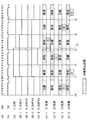
以下、図9を参照しながら、上述した燃料噴射制御によって得られる動作をとりまとめて説明する。まず、エンジン回転数NEおよびエンジン水温TWに応じて、筒内噴射時間の上リミット値TCYLD_LMTHが算出され(ステップ31)、この上リミット値TCYLD_LMTHから所定のヒステリシス量をDTCYLD_LMTを順次、差し引くことによって、筒内噴射時間の下リミット値TCYLD_LMTLおよび最大値TCYLD_MAXが算出される(ステップ32、35)。さらに、これら3つの値が、噴射時間−噴射量変換テーブルを用いて噴射量に変換され、筒内噴射量の上リミット値GCYLD_LMTH、下リミット値GCYLD_LMTLおよび最大値GCYLD_MAXが求められる(ステップ33、34、36)。
Hereinafter, the operations obtained by the above-described fuel injection control will be collectively described with reference to FIG. First, the upper limit value TCYLD_LMTH of the in-cylinder injection time is calculated according to the engine speed NE and the engine water temperature TW (step 31), and a predetermined hysteresis amount is subtracted from the upper limit value TCYLD_LMTH sequentially from the DTCYLD_LMT. A lower limit value TCYLD_LMTL and a maximum value TCYLD_MAX are calculated (
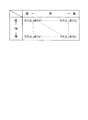
次に、要求燃料量GCYLと上記の筒内噴射量の3つのパラメータとの関係から、以下のケースA〜Dに応じて、噴射モードが設定されるとともに、筒内噴射量GCYLD#nおよびポート噴射量GCYLP#nが算出される。 Next, from the relationship between the required fuel amount GCYL and the above three parameters of the in-cylinder injection amount, the injection mode is set according to the following cases A to D, the in-cylinder injection amount GCYLD # n, and the port An injection amount GCYLP # n is calculated.
・ケースA(GCYL≦GCYLD_LMTL)
要求燃料量GCYLが下リミット値GCYLD_LMTL以下のときには、ポート噴射実行フラグF_DLMTが「0」にセットされ(ステップ40)、噴射モードがDIモードに設定される。これに伴い、筒内噴射量GCYLD#nが要求燃料量GCYLに設定される(ステップ26)とともに、ポート噴射量GCYLP#nは値0に設定される(ステップ27)。
・ Case A (GCYL ≦ GCYLD_LMTL)
When the required fuel amount GCYL is equal to or lower than the lower limit value GCYLD_LMTL, the port injection execution flag F_DLMT is set to “0” (step 40), and the injection mode is set to the DI mode. Accordingly, the in-cylinder injection amount GCYLD # n is set to the required fuel amount GCYL (step 26), and the port injection amount GCYLP # n is set to the value 0 (step 27).
・ケースB(GCYL:ケースAからのヒステリシス域)
上記のケースAから要求燃料量GCYLが増大し、上下のリミット値GCYLD_LMTH/L間のヒステリシス域に移行したときには(ステップ39:NO)、噴射モードはDIモードに維持される。その結果、ケースAと同様、筒内噴射量GCYLD#nは要求燃料量GCYLに、ポート噴射量GCYLP#nは値0に、それぞれ設定される。この場合、要求燃料量GCYLは上リミット値GCYLD_LMTHよりも小さいので、筒内噴射のみで要求燃料量GCYLを供給することができる。
Case B (GCYL: Hysteresis range from case A)
When the required fuel amount GCYL increases from the above case A and shifts to the hysteresis range between the upper and lower limit values GCYLD_LMTH / L (step 39: NO), the injection mode is maintained in the DI mode. As a result, as in case A, the in-cylinder injection amount GCYLD # n is set to the required fuel amount GCYL, and the port injection amount GCYLP # n is set to the
・ケースC(GCYL>GCYLD_LMTH)
上記のケースBから要求燃料量GCYLがさらに増大し、上リミット値GCYLD_LMTHを上回ると、ポート噴射実行フラグF_DLMTが「1」にセットされ(ステップ38)、噴射モードがDI・PIモードに切り換えられる。これに伴い、筒内噴射量GCYLD#nは最大値GCYLD_MAXに設定される(ステップ24)とともに、ポート噴射量GCYLP#nは、要求燃料量GCYLから最大値GCYLD_MAXを差し引いた値(=GCYL−GCYLD_MAX)に設定される(ステップ25)。
・ Case C (GCYL> GCYLD_LMTH)
When the required fuel amount GCYL further increases from the case B and exceeds the upper limit value GCYLD_LMTH, the port injection execution flag F_DLMT is set to “1” (step 38), and the injection mode is switched to the DI / PI mode. Accordingly, the in-cylinder injection amount GCYLD # n is set to the maximum value GCYLD_MAX (step 24), and the port injection amount GCYLP # n is a value obtained by subtracting the maximum value GCYLD_MAX from the required fuel amount GCYL (= GCYL-GCYLD_MAX). ) Is set (step 25).
図9から明らかなように、このときのポート噴射量GCYLP#nは、ポート噴射時間のヒステリシス量DTCYLD_LMTに相当する噴射量の2倍よりも大きな値になる。前述したように、このヒステリシス量DTCYLD_LMTは、ポート燃料噴射弁8の最小噴射時間よりも若干大きな値に設定されている。以上の関係から、ポート噴射量GCYLP#nが上記のように設定されることにより、ポート燃料噴射弁8の最小噴射時間の2倍を上回るポート噴射時間が確保されるので、ポート噴射量弁GCYLP#nを余裕をもって確実に供給することができる。
As is apparent from FIG. 9, the port injection amount GCYLP # n at this time is a value larger than twice the injection amount corresponding to the hysteresis amount DTCYLD_LMT of the port injection time. As described above, the hysteresis amount DTCYLD_LMT is set to a value slightly larger than the minimum injection time of the port
・ケースD(GCYL:ケースCからのヒステリシス域)
上記のケースCから要求燃料量GCYLが減少し、上下のリミット値GCYLD_LMTH/L間のヒステリシス域に移行したときには、噴射モードはDI・PIモードに維持される。その結果、ケースCと同様、筒内噴射量GCYLD#nは最大値GCYLD_MAXに、ポート噴射量GCYLP#nは(GCYL−GCYLD_MAX)に、それぞれ設定される。図9に示すように、この場合には、ポート燃料噴射弁8の最小噴射時間を上回るポート噴射時間が確保されるので、ポート噴射量弁GCYLP#nを確実に供給することができる。
・ Case D (GCYL: Hysteresis range from case C)
When the required fuel amount GCYL decreases from the above case C and shifts to the hysteresis range between the upper and lower limit values GCYLD_LMTH / L, the injection mode is maintained in the DI / PI mode. As a result, as in the case C, the in-cylinder injection amount GCYLD # n is set to the maximum value GCYLD_MAX, and the port injection amount GCYLP # n is set to (GCYL-GCYLD_MAX). As shown in FIG. 9, in this case, since the port injection time exceeding the minimum injection time of the port
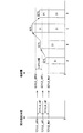
図10は、エンジン3の行程と各気筒3aにおける噴射モードの切換タイミングとの関係を示すタイミングチャートである。この例では、タイミングt0以前では、ポート噴射実行フラグF_DLMTが「0」にセットされており、それに応じて、4つの気筒別ポート噴射実行フラグF_DLMT#1〜#4もそれぞれ「0」にセットされ(図10(c)、(d)参照)、各気筒3aの噴射モードはDIモードに設定されている。また、気筒3aでの燃焼が#1→#3→#4→#2の順で行われ、t0のときには、#1気筒3aは、圧縮行程開始時のBDCにあり、したがって、#2〜#4気筒3aは、膨張行程開始時のTDC、吸気行程開始時のTDC、および排気行程開始時のBDCにあるものとする(図10(e)参照)。
FIG. 10 is a timing chart showing the relationship between the stroke of the
この状態から、要求燃料量GCYLが増大し、#1気筒3aの膨張行程の途中で上リミット値GCYL_LMTHを上回ると(ステップ37:YES)、ポート噴射実行フラグF_DLMTが「0」から「1」に切り換えられる(t1)。このとき、#1気筒3aは膨張行程にあり、#3気筒3aは圧縮行程にあることで、PISETSGL≦PISTG#1≦PISETSGHが成立し(ステップ41:YES)、それぞれの気筒別ポート噴射実行フラグF_DLMT#1、#3の切換が許可され、「1」に切り換えられることによって、噴射モードはDIモードからDI・PIモードに切り換えられる。
From this state, when the required fuel amount GCYL increases and exceeds the upper limit value GCYL_LMTH during the expansion stroke of the # 1 cylinder 3a (step 37: YES), the port injection execution flag F_DLMT is changed from “0” to “1”. It is switched (t1). At this time, because # 1 cylinder 3a is in the expansion stroke and # 3 cylinder 3a is in the compression stroke, PISETSGL
これに対し、このとき、#2気筒3aは排気行程にあり、#4気筒3aは吸気行程にあるため、前記ステップ41の判別結果がNOになることで、気筒別ポート噴射実行フラグF_DLMT#2、#4が前回値F_DLMT#2z、#4z(=0)に維持され(図10(d)−2、4)、それにより、噴射モードの切換が禁止され、噴射モードはDIモードに維持される。
On the other hand, at this time, because the # 2 cylinder 3a is in the exhaust stroke and the # 4 cylinder 3a is in the intake stroke, the determination result of the
これにより、#4気筒3aについては、吸気行程の途中、ポート噴射実行フラグF_DLMTの切換に同期して、噴射モードをDI・PIモードに切り換えた場合に生じる不具合を回避することができる。すなわち、そのように噴射モードを切り換えた場合、それに伴い、筒内噴射量GCYLD#4は、要求燃料量GCYL(図9のケースB)から、より小さな最大値GCYLD_MAX(同図のケースC)に変更される。このため、排気行程でのポート噴射が間に合わず、吸気行程での筒内噴射のみが行われた場合、#4気筒3aに実際に供給される燃料量が不足してしまう。これに対して、本実施形態では、上述したように、気筒別ポート噴射実行フラグF_DLMT#4の切換を禁止し、噴射モードを維持するので、そのような燃料量が不足するを回避することができる。
Thereby, for the # 4 cylinder 3a, it is possible to avoid a problem that occurs when the injection mode is switched to the DI / PI mode in synchronization with the switching of the port injection execution flag F_DLMT during the intake stroke. That is, when the injection mode is switched in this way, the in-cylinder injection
#4および#2気筒3aの気筒別ポート噴射実行フラグF_DLMT#4、#2は、その後、圧縮行程に移行したときに(t2、t3)、それぞれ「1」に切り換えられ、噴射モードはDI・PIモードに切り換えられる。
The cylinder-by-cylinder port injection execution flags
その後、要求燃料量GCYLが減少し、#1気筒3aの吸気行程の途中で、下リミット値GCYLD_LMTL以下になると(ステップ39:YES)、ポスト噴射実行フラグF_DLMTが「1」から「0」に切り換えられる(t4)。このとき、#2気筒3aは圧縮行程にあり、#4気筒3aは膨張行程にあり、すなわち切換の許可区間にあるため、気筒別ポート噴射実行フラグF_DLMT#2、#4の「0」への切換が許可され、噴射モードはDI・PIモードからDIモードに切り換えられる。
Thereafter, when the required fuel amount GCYL decreases and becomes lower than the lower limit value GCYLD_LMTL during the intake stroke of the # 1 cylinder 3a (step 39: YES), the post injection execution flag F_DLMT is switched from “1” to “0”. (T4). At this time, the # 2 cylinder 3a is in the compression stroke, and the # 4 cylinder 3a is in the expansion stroke, that is, in the switching-permitted section. Therefore, the cylinder-specific port injection execution flags
これに対して、このとき、#1気筒3aは吸気行程にあり、#3気筒3aは排気行程にあり、すなわち切換の禁止区間にあるため、気筒別ポート噴射実行フラグF_DLMT#1、#3は「1」に維持され、噴射モードがDI・PIモードに維持される。
On the other hand, at this time, the # 1 cylinder 3a is in the intake stroke and the # 3 cylinder 3a is in the exhaust stroke, that is, in the switching prohibition section, so that the cylinder specific port injection execution flags
これにより#1気筒3aについては、ポート噴射実行フラグF_DLMTの切換に同期して、噴射モードをDIモードに切り換えた場合に生じる不具合を回避することができる。すなわち、そのように噴射モードを切り換えた場合、それに伴い、筒内噴射量GCYLD#1は、最大値GCYLD_MAX(図9のケースD)から、より大きな要求燃料量GCYL(図9のケースA)に変更される。このため、排気行程においてDIモード用のポート噴射がすでに行われた場合には、筒内噴射の実行により、要求燃料量GCYL相当の燃料がさらに供給されることで、燃料量が過剰になってしまう。これに対して、本実施形態では、上述したように気筒別ポート噴射実行フラグF_DLMT#1の切換を禁止し、噴射モードを維持するので、燃料量が過剰になるのを回避することができる。
As a result, for the # 1 cylinder 3a, it is possible to avoid problems that occur when the injection mode is switched to the DI mode in synchronization with the switching of the port injection execution flag F_DLMT. That is, when the injection mode is switched in this way, the in-cylinder injection
#1および#3気筒3aの気筒別ポート噴射実行フラグF_DLMT#1、#3は、その後、圧縮行程に移行したときに(t5、t6)、それぞれ「0」に切り換えられることによって、噴射モードはDIモードに切り換えられる。
The cylinder-by-cylinder port injection execution flags
以上のように、本実施形態によれば、均質燃焼モード時、クランク角ステージFISTG#nを気筒3aごとに算出するとともに、このクランク角ステージFISTG#nが圧縮行程の始期に相当する下限値PISETSDLから膨張行程の終期に相当する上限値PISETSDHの許可区間以外の禁止区間にあるときに、その気筒3aに対し、噴射モードの切換を禁止する。このため、噴射モードのDIモードへの切換の際には、燃料の供給量が過剰になるのを回避できるとともに、DI・PIモードへの切換の際には、燃料の供給量が不足するのを回避できる。これにより、噴射モードの切換時に、エンジン3に要求される燃料量を各気筒3aに過不足なく供給でき、その結果、トルクの変動を抑制でき、良好なドライバビリティを確保することができる。
As described above, according to the present embodiment, in the homogeneous combustion mode, the crank angle stage FISTG # n is calculated for each cylinder 3a, and the crank angle stage FISTG # n is the lower limit value PISETSDL corresponding to the start of the compression stroke. When the cylinder 3a is in a prohibited zone other than the permitted zone of the upper limit value PISETSDH corresponding to the end of the expansion stroke, the switching of the injection mode is prohibited. Therefore, when the injection mode is switched to the DI mode, it is possible to avoid an excessive fuel supply amount, and when switching to the DI / PI mode, the fuel supply amount is insufficient. Can be avoided. Thereby, when the injection mode is switched, the amount of fuel required for the
なお、本発明は、説明した実施形態に限定されることなく、種々の態様で実施することができる。例えば、実施形態では、筒内燃料噴射弁およびポート燃料噴射弁による燃料の噴射期間を含む所定のクランク角度区間(禁止区間)として、排気行程および吸気行程の全区間を設定しているが、これに限らず、噴射モードの切換を行ったときに燃料の過不足が生じるおそれのある区間であればよい。例えば、実際に燃料の噴射が行われる期間に相当するクランク角度区間としてよく、あるいはポート噴射が行われない排気行程の前半部を禁止区間から除外してもよい。 In addition, this invention can be implemented in various aspects, without being limited to the described embodiment. For example, in the embodiment, all the sections of the exhaust stroke and the intake stroke are set as the predetermined crank angle section (prohibited section) including the fuel injection period by the cylinder fuel injection valve and the port fuel injection valve. However, the present invention is not limited to this, and any section in which excess or deficiency of fuel may occur when the injection mode is switched may be used. For example, a crank angle section corresponding to a period during which fuel is actually injected may be used, or the first half of the exhaust stroke in which port injection is not performed may be excluded from the prohibited section.
また、実施形態は、内燃機関の燃焼モードが均質燃焼モードを含む3つの燃焼モードで構成され、そのうちの均質燃焼モードに本発明を適用した例であるが、筒内噴射モードとポート噴射モードが切り換えられる燃焼モードである限り、本発明を適用してもよいことはもちろんである。 Further, the embodiment is an example in which the combustion mode of the internal combustion engine includes three combustion modes including the homogeneous combustion mode, and the present invention is applied to the homogeneous combustion mode, but the in-cylinder injection mode and the port injection mode are Of course, the present invention may be applied as long as the combustion mode is switched.
さらに、本実施形態は、本発明を車両用のエンジンに適用した例であるが、本発明は、これに限らず、クランク軸を鉛直方向に配置した船外機などのような船舶推進機用エンジンや他の産業用の内燃機関に適用してもよい。その他、本発明の趣旨の範囲内で、細部の構成を適宜、変更することが可能である。 Further, the present embodiment is an example in which the present invention is applied to an engine for a vehicle. However, the present invention is not limited to this, and is used for a marine propulsion device such as an outboard motor having a crankshaft arranged in a vertical direction. The present invention may be applied to engines and other industrial internal combustion engines. In addition, it is possible to appropriately change the detailed configuration within the scope of the gist of the present invention.
1 燃料噴射制御装置
2 ECU(要求燃料量算出手段、噴射モード決定手段、判定手段および噴射モード
切換禁止手段)
3 エンジン
3a 気筒
3f 吸気ポート
6 筒内燃料噴射弁
8 ポート燃料噴射弁
21 クランク角センサ(回転数検出手段およびクランク角検出手段)
22 アクセル開度センサ(負荷検出手段)
NE エンジン回転数(内燃機関の回転数)
AP アクセル開度(内燃機関の負荷)
GCYL 要求燃料量
DESCRIPTION OF
Switching prohibition means)
3
22 Accelerator opening sensor (load detection means)
NE engine speed (speed of internal combustion engine)
AP accelerator opening (load of internal combustion engine)
GCYL Required fuel amount
Claims (1)
前記内燃機関の回転数を検出する回転数検出手段と、
前記内燃機関の負荷を検出する負荷検出手段と、
前記検出された内燃機関の回転数および負荷に応じて、前記内燃機関に供給すべき要求燃料量を算出する要求燃料量算出手段と、
当該算出された要求燃料量に応じて、前記噴射モードを、前記筒内燃料噴射弁のみから燃料を噴射する筒内噴射モードと、前記筒内燃料噴射弁および前記ポート燃料噴射弁の双方から燃料を噴射する筒内・ポート噴射モードの一方に決定する噴射モード決定手段と、
前記内燃機関のクランク角を検出するクランク角検出手段と、
当該検出されたクランク角が、前記筒内燃料噴射弁および前記ポート燃料噴射弁による燃料の噴射期間を含む所定のクランク角度区間にあるか否かを、前記気筒ごとに判定する判定手段と、
前記検出されたクランク角が前記所定のクランク角度区間にあると判定された前記気筒に対して、前記噴射モード決定手段による決定に応じた前記噴射モードの切換を禁止する噴射モード切換禁止手段と、
を備えることを特徴とする内燃機関の燃料噴射制御装置。 A fuel injection control device for an internal combustion engine having an in-cylinder fuel injection valve for injecting fuel into a cylinder and a port fuel injection valve for injecting fuel into an intake port,
A rotational speed detection means for detecting the rotational speed of the internal combustion engine;
Load detecting means for detecting a load of the internal combustion engine;
A required fuel amount calculating means for calculating a required fuel amount to be supplied to the internal combustion engine according to the detected rotational speed and load of the internal combustion engine;
According to the calculated required fuel amount, the injection mode is divided into a cylinder injection mode in which fuel is injected only from the cylinder fuel injection valve, and fuel from both the cylinder fuel injection valve and the port fuel injection valve. Injection mode determining means for determining one of the in-cylinder and port injection modes for injecting
Crank angle detecting means for detecting a crank angle of the internal combustion engine;
Determination means for determining, for each cylinder, whether or not the detected crank angle is in a predetermined crank angle section including a fuel injection period by the in-cylinder fuel injection valve and the port fuel injection valve;
Injection mode switching prohibiting means for prohibiting switching of the injection mode according to the determination by the injection mode determining means for the cylinder determined to have the detected crank angle in the predetermined crank angle section;
A fuel injection control device for an internal combustion engine, comprising:
Priority Applications (1)
| Application Number | Priority Date | Filing Date | Title |
|---|---|---|---|
| JP2008031156A JP2009191663A (en) | 2008-02-12 | 2008-02-12 | Fuel injection control device for internal combustion engine |
Applications Claiming Priority (1)
| Application Number | Priority Date | Filing Date | Title |
|---|---|---|---|
| JP2008031156A JP2009191663A (en) | 2008-02-12 | 2008-02-12 | Fuel injection control device for internal combustion engine |
Publications (1)
| Publication Number | Publication Date |
|---|---|
| JP2009191663A true JP2009191663A (en) | 2009-08-27 |
Family
ID=41073916
Family Applications (1)
| Application Number | Title | Priority Date | Filing Date |
|---|---|---|---|
| JP2008031156A Pending JP2009191663A (en) | 2008-02-12 | 2008-02-12 | Fuel injection control device for internal combustion engine |
Country Status (1)
| Country | Link |
|---|---|
| JP (1) | JP2009191663A (en) |
Cited By (3)
| Publication number | Priority date | Publication date | Assignee | Title |
|---|---|---|---|---|
| WO2013061424A1 (en) * | 2011-10-26 | 2013-05-02 | トヨタ自動車 株式会社 | Fuel injection control device for internal combustion engine |
| WO2013061425A1 (en) * | 2011-10-26 | 2013-05-02 | トヨタ自動車 株式会社 | Fuel injection control device for internal combustion engine |
| WO2013061426A1 (en) * | 2011-10-26 | 2013-05-02 | トヨタ自動車 株式会社 | Fuel injection control device for internal combustion engine |
Citations (4)
| Publication number | Priority date | Publication date | Assignee | Title |
|---|---|---|---|---|
| JPS6028243U (en) * | 1983-08-01 | 1985-02-26 | 日産自動車株式会社 | Direct cylinder injection engine |
| JPS63138118A (en) * | 1986-11-28 | 1988-06-10 | Mazda Motor Corp | Stratified combustion control device for engine |
| JPH10103118A (en) * | 1996-09-25 | 1998-04-21 | Toyota Motor Corp | Fuel injection control device for in-cylinder injection internal combustion engine |
| JP2004270583A (en) * | 2003-03-10 | 2004-09-30 | Toyota Motor Corp | Fuel injection device for internal combustion engine |
-
2008
- 2008-02-12 JP JP2008031156A patent/JP2009191663A/en active Pending
Patent Citations (4)
| Publication number | Priority date | Publication date | Assignee | Title |
|---|---|---|---|---|
| JPS6028243U (en) * | 1983-08-01 | 1985-02-26 | 日産自動車株式会社 | Direct cylinder injection engine |
| JPS63138118A (en) * | 1986-11-28 | 1988-06-10 | Mazda Motor Corp | Stratified combustion control device for engine |
| JPH10103118A (en) * | 1996-09-25 | 1998-04-21 | Toyota Motor Corp | Fuel injection control device for in-cylinder injection internal combustion engine |
| JP2004270583A (en) * | 2003-03-10 | 2004-09-30 | Toyota Motor Corp | Fuel injection device for internal combustion engine |
Cited By (14)
| Publication number | Priority date | Publication date | Assignee | Title |
|---|---|---|---|---|
| WO2013061424A1 (en) * | 2011-10-26 | 2013-05-02 | トヨタ自動車 株式会社 | Fuel injection control device for internal combustion engine |
| WO2013061425A1 (en) * | 2011-10-26 | 2013-05-02 | トヨタ自動車 株式会社 | Fuel injection control device for internal combustion engine |
| WO2013061426A1 (en) * | 2011-10-26 | 2013-05-02 | トヨタ自動車 株式会社 | Fuel injection control device for internal combustion engine |
| CN103874844A (en) * | 2011-10-26 | 2014-06-18 | 丰田自动车株式会社 | Fuel injection control device for internal combustion engine |
| CN103890359A (en) * | 2011-10-26 | 2014-06-25 | 丰田自动车株式会社 | Fuel injection control device for internal combustion engine |
| CN103890358A (en) * | 2011-10-26 | 2014-06-25 | 丰田自动车株式会社 | Fuel injection control device for internal combustion engine |
| JPWO2013061424A1 (en) * | 2011-10-26 | 2015-04-02 | トヨタ自動車株式会社 | Fuel injection control device for internal combustion engine |
| JPWO2013061426A1 (en) * | 2011-10-26 | 2015-04-02 | トヨタ自動車株式会社 | Fuel injection control device for internal combustion engine |
| JPWO2013061425A1 (en) * | 2011-10-26 | 2015-04-02 | トヨタ自動車株式会社 | Fuel injection control device for internal combustion engine |
| US9447721B2 (en) | 2011-10-26 | 2016-09-20 | Toyota Jidosha Kabushiki Kaisha | Fuel injection control device for internal combustion engine |
| CN103874844B (en) * | 2011-10-26 | 2016-10-12 | 丰田自动车株式会社 | Fuel injection control device for internal combustion engine |
| CN103890359B (en) * | 2011-10-26 | 2016-10-12 | 丰田自动车株式会社 | The fuel injection control system of internal combustion engine |
| US9587577B2 (en) | 2011-10-26 | 2017-03-07 | Toyota Jidosha Kabushiki Kaisha | Fuel injection control device for internal combustion engine |
| US9631574B2 (en) | 2011-10-26 | 2017-04-25 | Toyota Jidosha Kabushiki Kaisha | Fuel injection control device for internal combustion engine |
Similar Documents
| Publication | Publication Date | Title |
|---|---|---|
| JP4434241B2 (en) | Internal combustion engine stop / start control device | |
| JP5548029B2 (en) | Control device for internal combustion engine | |
| JP4415876B2 (en) | Control device for internal combustion engine | |
| US20100037859A1 (en) | Control device for internal combustion engine, control method, program for performing control method | |
| EP1526277A2 (en) | Internal combustion engine control method | |
| EP1559896A2 (en) | Direct fuel injection/spark ignition engine control device | |
| JP4991589B2 (en) | Fuel injection control device for internal combustion engine | |
| EP1431556B1 (en) | Fuel injection controller for in-cylinder direct injection engine | |
| JP2009287493A (en) | Ignition timing control device for internal combustion engine | |
| JP2002276404A (en) | Compression ignition type internal combustion engine | |
| JP3893909B2 (en) | Control device for direct-injection spark-ignition internal combustion engine | |
| JP2009191663A (en) | Fuel injection control device for internal combustion engine | |
| JP2006194098A (en) | Fuel injection control device for internal combustion engine | |
| JP5593132B2 (en) | Control device for internal combustion engine | |
| JP2008163815A (en) | Fuel injection control device for internal combustion engine | |
| JP4738304B2 (en) | Control device for internal combustion engine | |
| JP4914807B2 (en) | Fuel injection control device for internal combustion engine | |
| JP5514635B2 (en) | Control device for internal combustion engine | |
| JP2012159005A (en) | Device and method for controlling fuel injection of internal combustion engine | |
| JP4604921B2 (en) | Control device for internal combustion engine | |
| JP2005009357A (en) | Control device for compression ignition type internal combustion engine | |
| JP4036198B2 (en) | Fuel injection control device for internal combustion engine | |
| JP2010138720A (en) | Ignition control device for engine | |
| US20220065200A1 (en) | Engine system | |
| JP2005016343A (en) | Control device for compression ignition type internal combustion engine |
Legal Events
| Date | Code | Title | Description |
|---|---|---|---|
| A621 | Written request for application examination |
Free format text: JAPANESE INTERMEDIATE CODE: A621 Effective date: 20101125 |
|
| A131 | Notification of reasons for refusal |
Free format text: JAPANESE INTERMEDIATE CODE: A131 Effective date: 20111227 |
|
| A977 | Report on retrieval |
Free format text: JAPANESE INTERMEDIATE CODE: A971007 Effective date: 20111227 |
|
| A521 | Written amendment |
Free format text: JAPANESE INTERMEDIATE CODE: A523 Effective date: 20120210 |
|
| A02 | Decision of refusal |
Free format text: JAPANESE INTERMEDIATE CODE: A02 Effective date: 20120417 |