JP2009190861A - High lift work vehicle - Google Patents
High lift work vehicle Download PDFInfo
- Publication number
- JP2009190861A JP2009190861A JP2008034774A JP2008034774A JP2009190861A JP 2009190861 A JP2009190861 A JP 2009190861A JP 2008034774 A JP2008034774 A JP 2008034774A JP 2008034774 A JP2008034774 A JP 2008034774A JP 2009190861 A JP2009190861 A JP 2009190861A
- Authority
- JP
- Japan
- Prior art keywords
- work vehicle
- aerial work
- telescopic boom
- basket
- mast
- Prior art date
- Legal status (The legal status is an assumption and is not a legal conclusion. Google has not performed a legal analysis and makes no representation as to the accuracy of the status listed.)
- Pending
Links
Images

Landscapes
- Forklifts And Lifting Vehicles (AREA)
Abstract
Description
本発明は、橋脚・橋梁側壁の工事等に用いられる高所作業車に関する。 The present invention relates to an aerial work vehicle used for construction of a bridge pier and a bridge sidewall.
一般に、橋脚・橋梁側壁等は経年劣化することから、定期的な点検はもとより所定年数毎に補修工事する必要があることが良く知られている。 In general, it is well known that piers, bridge sidewalls, and the like deteriorate over time, and that repair work is required every predetermined number of years as well as periodic inspections.
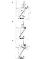
図3(b)は従来の垂直タイプの高所作業車を示す図である。図4は従来の直伸タイプの高所作業車を示す図である。図5は従来の屈伸タイプの高所作業車を示す図である。 FIG. 3B is a view showing a conventional vertical type aerial work vehicle. FIG. 4 is a view showing a conventional straight extension type aerial work vehicle. FIG. 5 is a view showing a conventional bending and stretching type aerial work vehicle.
図3(a)に示すように、橋脚301は敷地内(C部)に建設されているが、道路又は私有地(B部)がすぐに隣接する場合がある。
図3(b)は、道路又は私有地(B部)に、垂直タイプの高所作業車300を搬入する場合を示している。道路の場合は道路占有許可を取得し交通規制しながら、私有地が田畑の場合は地盤整備後に車両を搬入し工事していた。
道路占有許可が取れず、または地盤整備が困難の場合は図3(c)のように、敷地内(B部)に足場303を補修工事箇所の高架橋外側面(A面)まで迫り出す形状に組み、工事していた。
このように、従来の垂直タイプ高所作業車300は、バスケット(作業床)4が垂直移動のみである為、搬入場所において、補修工事以外の工数が必要となる問題があった。
As shown in FIG. 3A, the
FIG. 3B shows a case where a vertical type
If you do not have permission to occupy the road, or if it is difficult to maintain the ground, as shown in Fig. 3 (c), the
Thus, the conventional vertical type
図4(a)は、直伸タイプの高所作業車400を高架橋301下に搬入し、伸縮ブーム2の伸長・上昇操作にて、補修工事箇所の高架橋外側面(A面)近くへアプローチしていた。しかし、バスケット(作業床)4の作業面が高架橋外側面(A面)から離れるという問題があった。
図4(b)は、バスケット4を旋回した状態で補修工事箇所の高架橋外側面(A面)に寄せる図である。バスケット4の旋回範囲は、一般的に左右90°又は100°程度であるので、作業範囲が限定されるという問題があった。
図4(c)は、伸縮ブーム2の伸長・上昇操作によって、補修工事箇所の高架橋外側面(A面)近くへのアプローチは可能であるが、より高い壁面位置へアプローチする場合は、バスケット4と高架橋外側壁の下面角(D部)が接近してしまい、作業の危険性が高くなるという問題があった。
In FIG. 4 (a), a straight extension type
FIG.4 (b) is a figure approaching the viaduct outer surface (A surface) of a repair construction location in the state which rotated the basket 4. FIG. Since the turning range of the basket 4 is generally about 90 ° or 100 ° left and right, there is a problem that the working range is limited.
FIG. 4 (c) shows that the approach to the viaduct outer surface (A surface) near the repair work site can be performed by extending and raising the
図5(a)は、先端屈伸アーム付高所作業車500を高架橋301下に搬入し、伸縮ブーム2の伸長・上昇操作にて、補修工事箇所の高架橋外側面(A面)近くへアプローチしていた。壁面上部への移動も、伸縮ブーム2の伸長・上昇操作によってアプローチしていた。アーム上部501の起伏角度は垂直方向まで可能である長いアームを備える場合は(通常のアーム長さは1.5m程度)、その範囲内でアプローチが可能であるが、伸縮ブーム2の伸長・上昇の操作移動は効率が悪いという問題があった。
さらに、図5(b)に示すように、バスケット4を壁面に寄せる場合ブームが高架橋外側壁の下面角(D部)に接近し、作業の危険性が高くなるという問題があった。
Fig. 5 (a) shows that an aerial work platform 500 with a tip bending / extending arm is carried under the
Further, as shown in FIG. 5 (b), when the basket 4 is brought close to the wall surface, there is a problem that the boom approaches the lower surface corner (D portion) of the viaduct outer wall and the risk of work increases.
従来の高所作業車について、直伸タイプ高所作業車400が特許文献1に、先端屈伸アーム付高所作業車500が特許文献2に記載されている。
本発明は、上記のような従来の問題点に鑑みてなされたものであり、足場を組む/地盤整備する必要が無く、ブーム式高所作業車を橋梁下の敷地内に設置し、高所作業車の伸縮ブームの伸長・上昇操作と垂直昇降多段マストの昇降操作にて、橋梁外側面の工事を効率よく作業可能とする。さらに、橋の側壁の高さが高い場合でも、バスケットを旋回させる必要も無く、伸縮ブームの起伏範囲内であって垂直昇降多段マストの昇降範囲内であれば、壁面に十分手の届く範囲で作業可能であり、バスケットは高架橋外側壁の下面角から安全な離隔距離を確保し、アプローチの際の危険性が低くなり、壁面上部まで補修工事可能とする高所作業車を提供することにある。 The present invention has been made in view of the conventional problems as described above, and it is not necessary to build a scaffold / maintenance of the ground, and install a boom type aerial work vehicle in a site under a bridge. By extending and raising the telescopic boom of the work vehicle and raising and lowering the vertical lifting multistage mast, the work on the outer surface of the bridge can be performed efficiently. Furthermore, even if the height of the side wall of the bridge is high, there is no need to swivel the basket, and if it is within the undulation range of the telescopic boom and within the elevation range of the vertical elevating multistage mast, it is within the reach of the wall. It is possible to work, and the basket is intended to provide an aerial work vehicle that secures a safe separation distance from the lower corner of the viaduct outer wall, reduces the risk of approaching, and allows repair work up to the upper wall surface .
本発明は、走行手段を備えたブーム式高所作業車において、走行ユニット上に旋回自在に取り付けられた旋回台と、旋回台上部に取り付けられた支持片の支点と、一端を支点に軸支し、伸縮自在であると共に起伏可能に延在している伸縮ブームと、支点と伸縮ブームとの取り付け部分の反対側に位置し、昇降自在に取り付けられた垂直昇降多段マストと、垂直昇降多段マストの最上段マストに取り付けられたバスケットとを備える構成とした。 The present invention relates to a boom type aerial work vehicle equipped with traveling means, a swivel mounted on a traveling unit so as to be able to swivel, a fulcrum of a support piece mounted on the upper part of the swivel, and a shaft supported with one end as a fulcrum. A telescopic boom that is telescopic and extending in a undulating manner, and a vertically elevating multistage mast that is positioned on the opposite side of the mounting portion between the fulcrum and the telescopic boom, and that can be raised and lowered, and a vertical elevating multistage mast And a basket attached to the uppermost mast.
本発明が提供する高所作業車において、旋回台内部では、車両運転可能であると共に、伸縮ブームの制御及び垂直昇降多段マストの制御が可能である。 In the aerial work vehicle provided by the present invention, the vehicle can be operated inside the swivel, and the telescopic boom and the vertical elevating multistage mast can be controlled.
本発明が提供する高所作業車において、垂直昇降多段マストは、伸縮ブームに対し、回動可能である。 In the aerial work vehicle provided by the present invention, the vertical elevating multistage mast is rotatable with respect to the telescopic boom.
本発明が提供する高所作業車において、支点と伸縮ブームとの取り付け部分の反対側に設けられた平行取りシリンダにより、伸縮ブームが起伏した時でも、垂直昇降多段マストとバスケットとが地面に対し垂直状態を保つことを特徴とする。 In the aerial work platform provided by the present invention, the vertical lifting multi-stage mast and the basket are in contact with the ground even when the telescopic boom is raised and lowered by the parallel cylinder provided on the opposite side of the mounting portion between the fulcrum and the telescopic boom. It is characterized by maintaining a vertical state.
本発明が提供する高所作業車において、バスケットは折畳み式であってもよい。
また、バスケット内では、車両運転可能であると共に、伸縮ブームの制御及び垂直昇降多段マストの制御が可能である。
In the aerial work vehicle provided by the present invention, the basket may be foldable.
Further, in the basket, the vehicle can be operated, and the telescopic boom and the vertical elevating multistage mast can be controlled.
本発明の高所作業車は、ブーム式高所作業車を橋梁下の敷地内に設置し、高所作業車の伸縮ブームの伸長・上昇操作と垂直昇降多段マストの昇降操作にて、橋梁外側面の工事を効率よく補修工事可能とするので、足場を組む必要も無く、地盤整備を行う必要も無いので、短期の工事工数となる。 The aerial work vehicle according to the present invention has a boom type aerial work vehicle installed on the site under the bridge, and is operated by extending and raising the telescopic boom of the aerial work vehicle and lifting and lowering the vertical lifting multistage mast. Since the side work can be efficiently repaired, there is no need to build a scaffold and no need for ground preparation, resulting in a short construction man-hour.
補修工事箇所の高架橋外側面が高い場合でも、伸縮ブームの起伏範囲内であって垂直昇降多段マストの昇降範囲内であれば、バスケットを旋回させる必要が無く、上方まで十分手の届く範囲で補修工事可能である。さらに、バスケットは高架橋外側壁の下面角から安全な離隔距離を確保できるので、アプローチの際の危険性が低くなる。 Even if the outer surface of the viaduct at the repair work site is high, if it is within the ups and downs of the telescopic boom and within the up and down range of the vertical elevating multistage mast, it is not necessary to rotate the basket and repairs are made within the reach of the upper part. Construction is possible. Furthermore, the basket can secure a safe separation distance from the lower surface corner of the viaduct outer wall, so the risk of approach is reduced.
また、平行取りシリンダにより、伸縮ブームが起伏した時でも、垂直昇降多段マストとバスケットとが地面に対し垂直状態を保ち、安全性が確保される。 In addition, the parallel take-up cylinder ensures that the vertical lifting multi-stage mast and the basket remain vertical with respect to the ground even when the telescopic boom is raised and lowered, thereby ensuring safety.
以下、本発明による高所作業車の実施の形態について、図を用いて説明する。 Hereinafter, embodiments of an aerial work vehicle according to the present invention will be described with reference to the drawings.
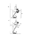
図1は本発明の走行手段を備えたブーム式高所作業車の構成図である。図2(a)〜(f)は、本発明の高所作業車を用いた作業手順を示す図である。 FIG. 1 is a block diagram of a boom type aerial work vehicle equipped with traveling means of the present invention. 2 (a) to 2 (f) are diagrams showing a work procedure using the aerial work vehicle of the present invention.
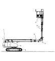
図1に示すように、ブーム式高所作業車の走行ユニット5と、走行ユニット5の上部に取り付けられた旋回台8と、旋回台8上部に取り付けられた支持片7に設けられた支点1を軸として延在する伸縮ブーム2を備える。伸縮ブーム2は、支点1を起点として伸縮自在であると共に起伏可能でもある。
支点1と伸縮ブーム2との取り付け部分の反対側には、垂直昇降多段マスト3が昇降自在に取り付けられている。
バスケット4は、伸縮ブーム2の伸縮機能により内外移動し、起伏機能により上昇する。さらにバスケット4は、垂直昇降多段マスト3の昇降機能により、垂直方向へ上下移動が可能となる。
As shown in FIG. 1, a
A vertical elevating multistage mast 3 is attached to the opposite side of the attachment portion between the
The basket 4 moves in and out by the telescopic function of the
垂直昇降多段マスト3の最上段マストには、バスケット4が取り付けられている。このバスケット4は、折畳み式であってもよく、折畳み式であれば収納時に場所を取らない。 A basket 4 is attached to the uppermost mast of the vertical elevating multistage mast 3. This basket 4 may be a foldable type, and if it is a foldable type, it does not take up space when stored.
ここで、旋回台8内部において、高所作業車の車両運転、伸縮ブーム2制御と垂直昇降多段マスト3の制御が可能である。さらに、バスケット4内においても同様の運転及び制御が可能である為、伸縮ブーム2を伸長起伏させ、垂直昇降多段マスト3を上昇させた状態でも、高所作業車の移動が可能となる。
Here, in the swivel base 8, vehicle operation of an aerial work vehicle,
また、車体設置位置と高架橋壁面との位置関係により、バスケット4の作業面と高架橋壁面が対面しない場合は、伸縮ブーム2に対する垂直昇降多段マスト3の回動機能を用いて、バスケット4の作業面を壁面に対面させることができる。
Further, when the work surface of the basket 4 and the viaduct wall surface do not face each other due to the positional relationship between the vehicle body installation position and the viaduct wall surface, the work surface of the basket 4 is used by using the rotating function of the vertical elevating multistage mast 3 with respect to the
平行取りシリンダ6は、支点1を起点として伸縮ブーム2が起伏している時に、垂直昇降多段マスト3とバスケット4が、地面に対して確実に垂直状態を保たせる機構である。これにより、伸縮ブーム2の起伏角度が大きくなっても、バスケット4の安全性が確保される。
The
図2は、本発明の高所作業車を用いた作業手順を説明する。 FIG. 2 illustrates a work procedure using the aerial work vehicle of the present invention.
まず、高所作業車を補修工事が必要とされる橋脚下301へ搬入する。図2(a)の通り、伸縮ブーム2が最も下方に位置する状態で搬入し、車両が補修工事箇所の高架橋外側面(A面)に対し平行に位置するように配置する。ここで、車両の水平機構は従来技術と同様であるので、説明を省略する。
First, an aerial work vehicle is carried into the
次に、支点1を起点として伸縮ブーム2を上方に起伏させる。図2(b)の通り、伸縮ブーム2を短縮させたまま(基本位置)起伏させる。
図から明らかなように、伸縮ブーム2を起伏させても、平行取りシリンダ6により、バスケット4は地面との垂直状態を保っている。
Next, the
As is apparent from the figure, even when the
そして、伸縮ブーム2を伸長させる。図2(c)は、バスケット4を補修工事箇所の高架橋外側面(A面)より外に位置する所まで伸縮ブーム2を伸長させた図である。
この図からも明らかなように、伸縮ブーム2を伸長させても、平行取りシリンダ6により、バスケット4は地面との垂直状態を保ち続ける。
Then, the
As is apparent from this figure, even when the
さらに、補修工事開始目標位置(ここでは高架橋外側壁の下部)付近まで起伏させる。
図2(d)からも明らかなように、伸縮ブーム2の起伏角度が大きくなっても、バスケット4は地面との垂直状態を保っている。
Furthermore, it will undulate to the vicinity of the repair work start target position (here, the lower part of the viaduct outer wall).
As is apparent from FIG. 2D, the basket 4 is kept in a vertical state with respect to the ground even when the undulation angle of the
また、補修工事開始目標位置付近より(図2(d))、補修工事箇所の高架橋外側面(A面)より外に位置する所まで伸長させた伸縮ブーム2(図2(c))を、作業者の作業範囲内へと伸縮ブーム2を短縮させる。図2(e)は、補修工事開始を示す図である。従来例の図4(c),図5(b)と比較して、高架橋外側壁の下面角(D部)への接近が無く、アプローチの際の危険性が低いことが分かる。
Further, from the vicinity of the repair work start target position (FIG. 2 (d)), the telescopic boom 2 (FIG. 2 (c)) extended to a position located outside the viaduct outer surface (A surface) of the repair work site, The
最後に、図2(f)は、補修工事箇所の高架橋外側面(A面)の下方より補修工事を開始し、垂直昇降多段マスト3を上昇させながら、順次上方へバスケット4を移動させている図である。垂直昇降多段マスト3の垂直方向の上昇により、より高所の補修工事目標位置においても作業が可能となることが分かる。なお、図示の通り、バスケット4は地面との垂直状態を維持している。 Lastly, in FIG. 2 (f), repair work is started from below the viaduct outer surface (A surface) of the repair work site, and the basket 4 is sequentially moved upward while raising the vertical elevating multistage mast 3. FIG. It can be seen that the vertical elevating multi-stage mast 3 can be operated even at higher repair work target positions due to the vertical elevation of the mast 3. As shown in the figure, the basket 4 maintains a vertical state with respect to the ground.
1 支点
2 伸縮ブーム
3 垂直昇降多段マスト
4 バスケット
5 走行ユニット
6 平行取りシリンダ
7 支持片
8 旋回台
1
Claims (6)
走行ユニットと、
前記走行ユニット上に旋回自在に取り付けられた旋回台と、
前記旋回台上部に取り付けられた支持片の支点と、
一端を前記支点に軸支し、伸縮自在であると共に起伏可能に延在している伸縮ブームと、
前記支点と前記伸縮ブームとの取り付け部分の反対側に位置し、昇降自在に取り付けられた垂直昇降多段マストと、
前記垂直昇降多段マストの最上段マストに取り付けられたバスケットとを備えることを特徴とする高所作業車。 In a boom type aerial work platform equipped with traveling means,
A traveling unit;
A swivel mounted pivotably on the traveling unit;
A fulcrum of a support piece attached to the upper part of the swivel;
A telescopic boom having one end pivotally supported by the fulcrum and extending and retractable,
A vertically elevating multistage mast that is located on the opposite side of the attachment portion of the fulcrum and the telescopic boom, and is attached to be freely raised and lowered,
An aerial work vehicle comprising: a basket attached to an uppermost mast of the vertical elevating multistage mast.
前記旋回台内部では、車両運転可能であると共に、前記伸縮ブームの制御及び前記垂直昇降多段マストの制御が可能であることを特徴とする高所作業車。 The aerial work vehicle according to claim 1,
An aerial work vehicle characterized by being capable of driving a vehicle inside the swivel, and controlling the telescopic boom and the vertical elevating multistage mast.
前記垂直昇降多段マストは、伸縮ブームに対し、回動可能であることを特徴とする高所作業車。 The aerial work vehicle according to claim 1,
The aerial work vehicle characterized in that the vertical elevating multistage mast is rotatable with respect to the telescopic boom.
前記支点と前記伸縮ブームとの取り付け部分の反対側に設けられた平行取りシリンダにより、
前記伸縮ブームが起伏した時でも、前記垂直昇降多段マストと前記バスケットとが地面に対し垂直状態を保つことを特徴とする高所作業車。 The aerial work vehicle according to claim 1,
By a parallel-cylinder cylinder provided on the opposite side of the mounting portion between the fulcrum and the telescopic boom,
The aerial work vehicle characterized in that the vertical lifting multi-stage mast and the basket maintain a vertical state with respect to the ground even when the telescopic boom is raised and lowered.
前記バスケットは折畳み式であることを特徴とする高所作業車。 The aerial work vehicle according to claim 1,
The aerial work vehicle characterized in that the basket is foldable.
前記バスケット内では、車両運転可能であると共に、前記伸縮ブームの制御及び前記垂直昇降多段マストの制御が可能であることを特徴とする高所作業車。 The aerial work vehicle according to claim 1,
An aerial work vehicle characterized in that in the basket, the vehicle can be operated, and the telescopic boom and the vertical elevating multistage mast can be controlled.
Priority Applications (1)
| Application Number | Priority Date | Filing Date | Title |
|---|---|---|---|
| JP2008034774A JP2009190861A (en) | 2008-02-15 | 2008-02-15 | High lift work vehicle |
Applications Claiming Priority (1)
| Application Number | Priority Date | Filing Date | Title |
|---|---|---|---|
| JP2008034774A JP2009190861A (en) | 2008-02-15 | 2008-02-15 | High lift work vehicle |
Publications (1)
| Publication Number | Publication Date |
|---|---|
| JP2009190861A true JP2009190861A (en) | 2009-08-27 |
Family
ID=41073222
Family Applications (1)
| Application Number | Title | Priority Date | Filing Date |
|---|---|---|---|
| JP2008034774A Pending JP2009190861A (en) | 2008-02-15 | 2008-02-15 | High lift work vehicle |
Country Status (1)
| Country | Link |
|---|---|
| JP (1) | JP2009190861A (en) |
Cited By (4)
| Publication number | Priority date | Publication date | Assignee | Title |
|---|---|---|---|---|
| ITTO20100316A1 (en) * | 2010-04-19 | 2011-10-20 | Merlo Project Srl | AIRCRAFT BOAT FOR LIFTING VEHICLES |
| ITVR20100073A1 (en) * | 2010-04-20 | 2011-10-21 | Cte S P A | TELESCOPIC AERIAL WORK PLATFORM |
| CN114105010A (en) * | 2022-01-24 | 2022-03-01 | 杭州恒宏机械有限公司 | Lifting mechanism |
| WO2022252566A1 (en) * | 2021-06-02 | 2022-12-08 | 湖南星邦智能装备股份有限公司 | Vertical movement mechanism and aerial work vehicle |
Citations (5)
| Publication number | Priority date | Publication date | Assignee | Title |
|---|---|---|---|---|
| JPH0940384A (en) * | 1995-08-02 | 1997-02-10 | Tadano Ltd | Machine for high lift work |
| JPH09263394A (en) * | 1996-03-29 | 1997-10-07 | Tadano Ltd | High lift work vehicle |
| JP2001063975A (en) * | 1999-08-27 | 2001-03-13 | Aichi Corp | Booming working vehicle |
| JP2002234690A (en) * | 2001-02-08 | 2002-08-23 | Aichi Corp | High-lift working vehicle for slope face working |
| JP2002362890A (en) * | 2001-06-07 | 2002-12-18 | Aichi Corp | Lifting device |
-
2008
- 2008-02-15 JP JP2008034774A patent/JP2009190861A/en active Pending
Patent Citations (5)
| Publication number | Priority date | Publication date | Assignee | Title |
|---|---|---|---|---|
| JPH0940384A (en) * | 1995-08-02 | 1997-02-10 | Tadano Ltd | Machine for high lift work |
| JPH09263394A (en) * | 1996-03-29 | 1997-10-07 | Tadano Ltd | High lift work vehicle |
| JP2001063975A (en) * | 1999-08-27 | 2001-03-13 | Aichi Corp | Booming working vehicle |
| JP2002234690A (en) * | 2001-02-08 | 2002-08-23 | Aichi Corp | High-lift working vehicle for slope face working |
| JP2002362890A (en) * | 2001-06-07 | 2002-12-18 | Aichi Corp | Lifting device |
Cited By (5)
| Publication number | Priority date | Publication date | Assignee | Title |
|---|---|---|---|---|
| ITTO20100316A1 (en) * | 2010-04-19 | 2011-10-20 | Merlo Project Srl | AIRCRAFT BOAT FOR LIFTING VEHICLES |
| ITVR20100073A1 (en) * | 2010-04-20 | 2011-10-21 | Cte S P A | TELESCOPIC AERIAL WORK PLATFORM |
| EP2380846A1 (en) * | 2010-04-20 | 2011-10-26 | CTE S.p.A. | Telescopic aerial work platform |
| WO2022252566A1 (en) * | 2021-06-02 | 2022-12-08 | 湖南星邦智能装备股份有限公司 | Vertical movement mechanism and aerial work vehicle |
| CN114105010A (en) * | 2022-01-24 | 2022-03-01 | 杭州恒宏机械有限公司 | Lifting mechanism |
Similar Documents
| Publication | Publication Date | Title |
|---|---|---|
| KR101213713B1 (en) | Boom control device of high place operation car | |
| JP2009190861A (en) | High lift work vehicle | |
| JP2014101194A (en) | Crane for being mounted on track/land vehicle | |
| JP5121351B2 (en) | Mobile crane | |
| RU2520630C1 (en) | Working vehicle with height-adjustable cabin | |
| JP5121352B2 (en) | Mobile crane | |
| JP5390113B2 (en) | Work vehicle | |
| US20080230320A1 (en) | Vehicle for High Lift Work | |
| JP7303094B2 (en) | work vehicle | |
| JP7336363B2 (en) | work vehicle | |
| JP3638485B2 (en) | Work vehicle jack equipment | |
| JP7213666B2 (en) | Safety device for aerial work platform | |
| KR20110019806A (en) | Movable ladder | |
| JP4528688B2 (en) | Work vehicle | |
| RU2609671C2 (en) | Mast hoisting device | |
| JP2005082331A (en) | Control device for high lift work vehicle | |
| JP2009007129A (en) | Climbing crane | |
| JP2003226492A (en) | Horizontally controlling device of workbench in vehicle for work at height | |
| JP4199819B2 (en) | Control device for telescopic boom type work machine | |
| JP7337669B2 (en) | work vehicle | |
| JP2012030943A (en) | High lift working vehicle | |
| JP2009040599A (en) | Mobile crane | |
| JP2002020095A (en) | Device for high lift work | |
| JPH0967091A (en) | Vehicle for high lift work | |
| JP4849724B2 (en) | Boom type aerial work equipment |
Legal Events
| Date | Code | Title | Description |
|---|---|---|---|
| A621 | Written request for application examination |
Free format text: JAPANESE INTERMEDIATE CODE: A621 Effective date: 20110201 |
|
| A977 | Report on retrieval |
Effective date: 20121114 Free format text: JAPANESE INTERMEDIATE CODE: A971007 |
|
| A131 | Notification of reasons for refusal |
Free format text: JAPANESE INTERMEDIATE CODE: A131 Effective date: 20121120 |
|
| A02 | Decision of refusal |
Effective date: 20130312 Free format text: JAPANESE INTERMEDIATE CODE: A02 |