JP2009181663A - Optical pickup device - Google Patents
Optical pickup device Download PDFInfo
- Publication number
- JP2009181663A JP2009181663A JP2008021663A JP2008021663A JP2009181663A JP 2009181663 A JP2009181663 A JP 2009181663A JP 2008021663 A JP2008021663 A JP 2008021663A JP 2008021663 A JP2008021663 A JP 2008021663A JP 2009181663 A JP2009181663 A JP 2009181663A
- Authority
- JP
- Japan
- Prior art keywords
- optical
- actuator
- disk
- recording medium
- actuator body
- Prior art date
- Legal status (The legal status is an assumption and is not a legal conclusion. Google has not performed a legal analysis and makes no representation as to the accuracy of the status listed.)
- Withdrawn
Links
- 230000003287 optical effect Effects 0.000 title claims abstract description 143
- 230000004075 alteration Effects 0.000 claims description 4
- 230000001105 regulatory effect Effects 0.000 abstract 1
- 238000006073 displacement reaction Methods 0.000 description 15
- 239000000463 material Substances 0.000 description 3
- 238000000034 method Methods 0.000 description 3
- 229910000881 Cu alloy Inorganic materials 0.000 description 2
- 239000000428 dust Substances 0.000 description 2
- 230000002093 peripheral effect Effects 0.000 description 2
- 239000000853 adhesive Substances 0.000 description 1
- 230000001070 adhesive effect Effects 0.000 description 1
- 238000013459 approach Methods 0.000 description 1
- 239000004020 conductor Substances 0.000 description 1
- 238000012937 correction Methods 0.000 description 1
- 238000013500 data storage Methods 0.000 description 1
- 230000006870 function Effects 0.000 description 1
- 230000010365 information processing Effects 0.000 description 1
- 238000012986 modification Methods 0.000 description 1
- 230000004048 modification Effects 0.000 description 1
- 238000000465 moulding Methods 0.000 description 1
- 238000012545 processing Methods 0.000 description 1
- 238000005476 soldering Methods 0.000 description 1
- 239000000758 substrate Substances 0.000 description 1
Images


Landscapes
- Optical Head (AREA)
- Optical Recording Or Reproduction (AREA)
Abstract
Description
本発明は、光ディスク再生装置などに使用される光ピックアップ装置に関する。 The present invention relates to an optical pickup device used for an optical disk reproducing device or the like.
光ディスク再生装置には、CD(Compact Disk)やDVD(Digital Versatile Disc)やBD(Blu-ray Disc)などのディスク形記録媒体としての光ディスクに記録された情報を読み取るために従来から種々の光ピックアップ装置(例えば、特許文献1参照)が用いられている。 Various kinds of optical pickups have been conventionally used for reading information recorded on an optical disk as a disk-type recording medium such as a CD (Compact Disk), a DVD (Digital Versatile Disc), or a BD (Blu-ray Disc). An apparatus (for example, see Patent Document 1) is used.
前述した特許文献1などに示された光ピックアップ装置は、前述したCDなどの光ディスクの径方向に移動自在に設けられたピックアップベースと、光ディスクに間隔をあけて相対した対物レンズが取り付けられたアクチュエータ本体と、アクチュエータ本体を光ディスクの径方向と厚み方向との双方に移動自在にピックアップベースに取り付けたアクチュエータ駆動部とを備えている。
The optical pickup device disclosed in
ピックアップベースには、光ディスクの周方向に互いに間隔をあけかつ互いの間に前記アクチュエータ本体を位置付けたマグネットが取り付けられている。アクチュエータ本体には、前記マグネットと間隔をあけて相対したプリントコイルが取り付けられている。アクチュエータ駆動部は、銅合金などの弾性力を備えるとともに高い導電性の材料で構成された線状弾性部材を複数備えている。 Magnets that are spaced apart from each other in the circumferential direction of the optical disk and that position the actuator body between them are attached to the pickup base. A printed coil is attached to the actuator body so as to face the magnet with a gap. The actuator driving unit includes a plurality of linear elastic members that are made of a highly conductive material and have an elastic force such as a copper alloy.
線状弾性部材は、一端部がアクチュエータ本体に取り付けられかつ他端部がピックアップベースに取り付けられている。線状弾性部材は、その長手方向が光ディスクの周方向に沿っている。線状弾性部材は、弾性変形自在であるので、ピックアップベースに対してアクチュエータ本体を変位自在に支持している。 The linear elastic member has one end attached to the actuator body and the other end attached to the pickup base. The longitudinal direction of the linear elastic member is along the circumferential direction of the optical disc. Since the linear elastic member is elastically deformable, the actuator main body is supported so as to be displaceable with respect to the pickup base.
さらに、線状弾性部材は、前述した一端部がプリントコイルと電気的に接続されて、ピックアップベース側の他端部が外部からフォーカス制御やトラッキング制御のための電流が供給される。 Further, the linear elastic member has one end portion electrically connected to the printed coil, and the other end portion on the pickup base side is supplied with a current for focus control and tracking control from the outside.
前述した構成の光ピックアップ装置は、プリントコイルに線状弾性部材を介して、フォーカス制御やトラッキング制御のための電流が供給されて、プリントコイルとマグネットとが互いに協働して、アクチュエータ本体即ち対物レンズを少なくとも光ディスクの厚み方向即ちフォーカス方向と光ディスクの径方向即ちトラッキング方向との双方に沿って移動させて、光ディスクの情報記録面の所望の位置にレーザ光を照射する。こうして、光ピックアップ装置は、当該光ディスクから情報を読み出す。
前述した光ピックアップ装置は、光ディスクから情報を読み出す際には、前記線状弾性部材を介してプリントコイルに電流を供給して、対物レンズの焦点を常に情報記録面の所望の位置に合わせている。このため、外部から振動などが加わっても、アクチュエータ本体がピックアップベースに対して振動することを抑制することができ、対物レンズが光ディスクに接触することを防止している。また、光ディスクから情報を読み出していない状態では、線状弾性部材を介してプリントコイルに電流を供給されていないために、外部から振動などが加わると、線状弾性部材の弾性により、アクチュエータ本体がピックアップベースに対して自由振動してしまう。このような場合でも対物レンズが光ディスクに接触しないように、対物レンズより先に光ディスクに接触し、かつ、接触部が光ディスクを傷つけにくい材料からなる突起がアクチュエータ本体に設けられている。 When reading the information from the optical disk, the optical pickup device described above supplies current to the print coil via the linear elastic member so that the objective lens is always focused on a desired position on the information recording surface. . For this reason, even if vibration is applied from the outside, the actuator body can be prevented from vibrating with respect to the pickup base, and the objective lens is prevented from coming into contact with the optical disk. In addition, when no information is read from the optical disk, no current is supplied to the printed coil via the linear elastic member. Therefore, when vibration is applied from the outside, the actuator body is moved by the elasticity of the linear elastic member. Free vibration with respect to the pickup base. In such a case, the actuator body is provided with a protrusion made of a material that comes into contact with the optical disk prior to the objective lens and whose contact portion does not easily damage the optical disk so that the objective lens does not contact the optical disk.
しかしながら、前述した突起が光ディスクを傷付けにくい材料であっても、振動の大きさや回数が増大すると光ディスクに接触の痕が残り、最悪の場合には、光ディスクを傷つけてしまう。さらに、突起の先端に塵埃等が付着すると、突起に付着した塵埃が振動により光ディスクに接触することで光ディスクを傷つけてしまう。 However, even if the above-described protrusion is a material that does not easily damage the optical disk, when the magnitude and number of vibrations increase, contact marks remain on the optical disk, and in the worst case, the optical disk is damaged. Further, when dust or the like adheres to the tip of the protrusion, the dust attached to the protrusion comes into contact with the optical disk due to vibration, thereby damaging the optical disk.
したがって、本発明の目的は、例えば、ディスク形記録媒体から情報を読み出していないときであっても、アクチュエータ本体がディスク形記録媒体に衝突することを防止することができる光ピックアップ装置を提供することにある。 Accordingly, an object of the present invention is to provide an optical pickup device capable of preventing the actuator body from colliding with a disk-shaped recording medium even when information is not read from the disk-shaped recording medium, for example. It is in.
前記課題を解決し目的を達成するために、請求項1に記載の本発明は、ディスク形記録媒体の径方向に移動自在に設けられたピックアップベースと、前記ディスク形記録媒体に間隔をあけて相対した対物レンズが取り付けられたアクチュエータ本体と、前記アクチュエータ本体を前記ディスク形記録媒体の少なくとも径方向と厚み方向とに移動自在に前記ピックアップベースに取り付けたアクチュエータ駆動部と、を備えた光ピックアップ装置において、前記ピックアップベースに設けられかつ前記ディスク形記録媒体から情報を読み取るためのレーザ光が通される光学部品を移動する駆動源と、前記駆動源の駆動力により、前記アクチュエータ本体が前記ディスク形記録媒体に接触することを規制する規制位置と、前記アクチュエータ本体が前記ディスク形記録媒体に接触することを許容する許容位置とに亘って移動自在に設けられた制限部材と、を備えたことを特徴としている。
In order to solve the above-mentioned problems and achieve the object, the present invention as claimed in
以下、本発明の一実施形態にかかる光ピックアップ装置を説明する。本発明の一実施形態にかかる光ピックアップ装置は、ピックアップベースに設けられた駆動源の駆動力により、アクチュエータ本体がディスク形記録媒体に接触することを規制する規制位置と接触することを許容する許容位置とに亘って移動自在な制限部材を設けている。このため、ディスク形記録媒体から情報を読み出していないときには、制限部材を規制位置に位置付けることにより、アクチュエータ本体がディスク形記録媒体に衝突することを防止することができる。 Hereinafter, an optical pickup device according to an embodiment of the present invention will be described. An optical pickup device according to an embodiment of the present invention allows an actuator main body to come into contact with a restriction position that restricts the actuator body from coming into contact with a disk-type recording medium by a driving force of a driving source provided in the pickup base. A restricting member that is movable over the position is provided. For this reason, when information is not read from the disk-shaped recording medium, the actuator body can be prevented from colliding with the disk-shaped recording medium by positioning the restricting member at the restricting position.
また、制限部材は、規制位置に位置付けられるとアクチュエータ本体をピックアップベースに固定する固定部を備えても良い。この場合、ディスク形記録媒体から情報を読み出していないときに、制限部材を規制位置に位置付けると、アクチュエータ本体が固定されるので、アクチュエータ本体がディスク形記録媒体に衝突することをより安定して防止することができる。 Further, the restricting member may include a fixing portion that fixes the actuator body to the pickup base when positioned in the restricting position. In this case, when the information is not read from the disk-type recording medium, the actuator main body is fixed when the restricting member is positioned at the restriction position, so that the actuator main body can be more stably prevented from colliding with the disk-type recording medium. can do.
さらに、制限部材は、光学部品が取り付けられても良い。この場合、アクチュエータ本体の移動を制限するための専用に制限部材を設ける必要がなくなるので、部品点数の削減を図ることができる。 Furthermore, the limiting member may be attached with an optical component. In this case, there is no need to provide a restricting member exclusively for restricting the movement of the actuator body, so that the number of parts can be reduced.
さらに、制限部材は、多層のディスク形記録媒体から情報を読み出す場合には、記録面の層に応じて所定の範囲内に位置する複数の許容位置のいずれかに移動してレーザ光の収差を補正し、ディスク形記録媒体から情報を読み出さない場合には、所定の範囲外に位置する規制位置に移動しても良い。この場合、ディスク形記録媒体から情報を読み出している際に制限部材が規制位置に位置することがないので、情報の読み出し中にアクチュエータ本体の移動を規制してしまうことを防止することができる。 Furthermore, when reading information from a multi-layer disc-shaped recording medium, the restricting member moves to any one of a plurality of allowable positions located within a predetermined range according to the layer of the recording surface to reduce the aberration of the laser beam. If correction is performed and information is not read from the disk-type recording medium, the information may be moved to a restriction position located outside a predetermined range. In this case, since the restricting member is not positioned at the restricting position when reading information from the disk-type recording medium, it is possible to prevent the movement of the actuator body from being restricted during the reading of information.
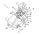
本発明の第1の実施例にかかる光ピックアップ装置1を、図1ないし図6を参照して説明する。光ピックアップ装置1は、CD、DVD、BD等のディスク形記録媒体としての光ディスクD(図2、図4及び図6中に示す)に記録された情報を再生する情報処理装置としての光ディスク再生装置などに用いられ、光ディスクDに記録された情報を読み取るために、光ディスクDの反りや振れに対して光ディスクDの情報記録面と後述する対物レンズ11との距離を制御するフォーカス制御と、光ディスクDのトラックの偏心に対して対物レンズ11を追従するように制御するトラッキング制御等を行うとともに、再生する光ディスクDが多層のBDである場合には、再生する記録面の層に応じて後述するコリメータレンズ7の位置の変更を行う。
An
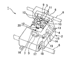
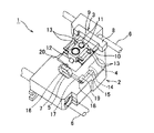
光ピックアップ装置1は、図1に示すように、ピックアップベース2と、アクチュエータ装置3と、駆動源としてのモータ4と、制限部材としてのレンズホルダ5と、制御手段としての図示しないμCOMを備えている。ピックアップベース2は、図示しないモータや当該モータからの駆動力により軸芯回りに回転駆動するリードスクリュー6などによって、当該リードスクリュー6上を光ディスクDの径方向に沿って移動可能に設けられている。
As shown in FIG. 1, the
ピックアップベース2は、箱状に形成され、かつ光学部品としての光源、コリメータレンズ7、ビームスプリッタ、受光器などが収容されている。前述した光源、コリメータレンズ7、ビームスプリッタ、受光器などの光学部品は、光源が光ディスクDから情報を読み取るために最適な波長のレーザ光を発生し、このレーザ光をディスクDまで導き、当該光ディスクDから反射されたレーザ光を受光器まで導いて、当該受光器で受光する。
The
アクチュエータ装置3は、図1に示すように、アクチュエータベース8と、アクチュエータ本体9と、アクチュエータ駆動部10とを備えている。
As shown in FIG. 1, the
アクチュエータベース8は、ピックアップベース2に固定されている。また、このアクチュエータベース8とピックアップベース2とには、アクチュエータ本体9を光ディスクDの周方向に沿って互いの間に挟む位置に配置されたマグネット(図示しない)が取り付けられている。
The
アクチュエータ本体9は、扁平な箱状に形成され、かつ光ディスクDと相対する対物レンズ11と図示しないプリントコイルが取り付けられている。
The
対物レンズ11は、図示例では、二つ設けられている。図1中手前側の一方の対物レンズ11は、CD及びDVD用のレーザ光を通すものであり、図1中奥側の他方の対物レンズ11は、BD用のレーザ光を通すものである。これらの対物レンズ11は、情報読み取り用の光源から発せられて光学部品を経由してきたレーザ光を通して、当該レーザ光を光ディスクDに照射することおよび光ディスクDから反射されたレーザ光を通して、当該レーザ光を光学部品へ出力するためのレンズである。
In the illustrated example, two
プリントコイルは、図示例では、二つ設けられる。これらのプリントコイルは、それぞれ、マグネットと間隔をあけて相対している。プリントコイルは、周知の接着剤などによりアクチュエータ本体9に取り付けられている。プリントコイルは、基板上にコイルの配線パターンが形成されたものであり、フォーカス制御用のコイルとトラッキング制御用のコイルが夫々形成されている。また、プリントコイルには、後述する線状弾性部材13とはんだ付けにて電気的に接続される。
In the illustrated example, two print coils are provided. Each of these printed coils is opposed to the magnet with a gap. The printed coil is attached to the
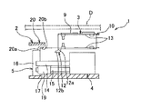
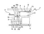
また、アクチュエータ本体9には、図2に示すように、突出片12が設けられている。突出片12は、アクチュエータ本体9のアクチュエータベース8から離れた側の先端でかつピックアップベース2寄りの縁に設けられている。突出片12は、前記アクチュエータ本体9の縁からピックアップベース2に向かって凸の鉛直部12aと、この鉛直部12aの先端から光ディスクDの周方向に沿って凸の水平部12bとを一体に備えている。
The
アクチュエータ駆動部10は、前述したマグネットと、前述したプリントコイルと、複数の線状弾性部材13を備えている。線状弾性部材13は、例えば銅合金などの弾性力を備えて導電性の良い材料で構成されて、直線状に延在した棒状(線状)に形成されている。線状弾性部材13は、図示例では、四つ設けられ、それぞれ、光ディスクDの周方向と平行に配置されている。これら四つの線状弾性部材13のうち一対の線状弾性部材13と他の一対の線状弾性部材13とは、互いに光ディスクDの径方向に間隔をあけて配置され、かつ、各対の線状弾性部材13は、互いに光ディスクDの厚み方向に間隔をあけて配置されている。
The
また、各線状弾性部材13は、その一端部がアクチュエータ本体9に取り付けられ、他端部がアクチュエータベース8に取り付けられている。アクチュエータ本体9とアクチュエータベース8と線状弾性部材13は、インサート成形により、これらのアクチュエータ本体9とアクチュエータベース8を成形する際に一体に成形される。すなわち、線状弾性部材13は、一端部がアクチュエータ本体9に内包され、他端部がアクチュエータベース8に内包されるとともに、他の部分(即ち、中央部)は露出した状態で固定される。
Each linear
さらに、線状弾性部材13は、アクチュエータ本体9側の一端部がプリントコイルと電気的に接続されているとともに、アクチュエータベース8側の他端部が外部からフォーカス制御やトラッキング制御のための電流が供給される。つまり、線状弾性部材13は、弾性変形することで、アクチュエータ本体9をアクチュエータベース8即ちピックアップベース2に対して移動自在に支持しているとともに、プリントコイルに電流を供給する配線の機能も合わせて持つ。
Furthermore, the linear
アクチュエータ駆動部10は、線状弾性部材13が弾性変形しかつ前述した制御のための電流が供給されたプリントコイルとマグネットにより、アクチュエータ本体9を光ディスクDの少なくとも径方向と厚み方向とに移動自在にアクチュエータベース8を介してピックアップベース2に取り付けている。
The
モータ4は、ピックアップベース2内に収容されて、当該ピックアップベース2に固定されている。モータ4は、その出力軸にねじ軸14が取り付けられている。ねじ軸14の長手方向は、光ディスクDの周方向と平行に配置されている。また、モータ4は、光ディスクDの径方向に沿ってアクチュエータ装置3と並ぶ位置に配置されている。更に、モータ4の出力軸に取り付けられたねじ軸14の近傍には、当該ねじ軸14と平行なガイドシャフト15が設けられている。
The
レンズホルダ5は、枠状の枠状部16と、棒状部17とを一体に備えている。枠状部16は、内側に光学部品としての前述したコリメータレンズ7を収容して、当該コリメータレンズ7が取り付けられている。棒状部17は、枠状部16の外周面から当該枠状部16の外周方向に直線状に延在している。棒状部17の枠状部16から離れた側の先端部には、内側にガイドシャフト15を通す通し孔18と、前記ねじ軸14に螺合するナット部19とが設けられている。
The
レンズホルダ5は、モータ4の駆動力によりねじ軸14が軸芯周りに回転されると、ナット部19がねじ軸14に螺合しているので、通し孔18によりガイドシャフト15に案内されながら、ねじ軸14の長手方向に沿って移動する。そして、レンズホルダ5は、アクチュエータ装置3に対してコリメータレンズ7を接離させる。そして、モータ4は、再生する光ディスクDが多層のBDである場合には、再生する記録面の層に応じてレンズホルダ5及びコリメータレンズ7を光ディスクDの周方向に移動させて、対物レンズ11の光ディスクDの情報記録面上での球面収差が適切となる位置にコリメータレンズ7の位置を変更する。
When the
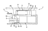
また、レンズホルダ5は、変位制限部20を一体に備えている。変位制限部20は、枠状部16のアクチュエータ装置3寄りの外縁部に設けられている。変位制限部20は、図2に示すように、枠状部16の前述した外縁部から光ディスクDに向かって立設した鉛直立設部20aと、この鉛直立設部20aの枠状部16の先端からアクチュエータ装置3に向かって延在した水平延在部20bとを一体に備えている。
Further, the
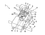
さらに、レンズホルダ5は、モータ4によりねじ軸14の長手方向に沿って移動されると、図5及び図6に示す規制位置と、図1乃至図4に示す許容位置とに亘って、移動される。即ち、レンズホルダ5は、規制位置と、許容位置とに亘って移動自在に設けられている。
Further, when the
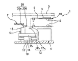
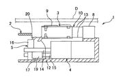
規制位置では、図6に示すように、突出片12の水平部12bと変位制限部20の水平延在部20bとが光ディスクDの厚み方向に沿って互いに間隔をあけて重なる。このとき、線状弾性部材13が弾性変形していない状態において、アクチュエータ本体9と光ディスクDとの間隔T1よりも水平部12bと水平延在部20bとの間隔T2が狭くなっている。このため、規制位置では、線状弾性部材13が弾性変形して水平部12bと水平延在部20bとが互いに接触しても、アクチュエータ本体9が光ディスクDに接触しない。このように、規制位置では、変位制限部20は、突出片12と協働して、アクチュエータ本体9が光ディスクDに接触することを規制する。
In the restricting position, as shown in FIG. 6, the
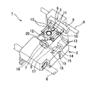
許容位置では、突出片12の水平部12bと変位制限部20の水平延在部20bとが光ディスクDの厚み方向に沿って互いに間隔をあけて重ならない。このため、許容位置では、線状弾性部材13が弾性変形すると、アクチュエータ本体9が光ディスクDに接触することが可能となる。このように、許容位置では、変位制限部20は、アクチュエータ本体9が光ディスクDに接触することを許容する。なお、許容位置とは、レンズホルダ5の規制位置以外の位置をなしている。このため、レンズホルダ5の許容位置とは、水平部12bと水平延在部20bとが光ディスクDの厚み方向に沿って互いに重ならないねじ軸14の長手方向の所定の範囲に形成されている。なお、図1及び図2は、許容位置におけるレンズホルダ5のアクチュエータ装置3から最も離れた位置を示し、図3及び図4は、許容位置におけるレンズホルダ5の最もアクチュエータ装置3寄りの位置を示している。すなわち、レンズホルダ5は、多層の光ディスクDから情報を読み出す場合には、記録面の層に応じて所定の範囲内(図1の位置から図3の位置までの範囲内)に位置する複数の許容位置のいずれかに移動して情報記録面上での球面収差を補正し、情報を読み出さない場合には、所定の範囲外に位置する規制位置(図6の位置)に移動する。
At the allowable position, the
μCOMは、プログラムに従って各種の処理を行う中央処理ユニット(CPU)と、CPUが行う処理のプログラムなどを格納した読み取り専用のメモリであるROMと、CPUでの各種の処理過程で利用するワークエリア、各種データを格納するデータ格納エリアなどを有する読み取り書き込み自在のメモリであるRAMなどを内蔵し、これらがバスラインによって互いに接続されている。 The μCOM includes a central processing unit (CPU) that performs various processes according to a program, a ROM that is a read-only memory that stores a program for processes performed by the CPU, a work area that is used in various processes performed by the CPU, A RAM, which is a readable / writable memory having a data storage area for storing various data, is built in, and these are connected to each other by a bus line.
μCOMは、アクチュエータ駆動部10のプリントコイルに接続して、当該プリントコイルに供給される前述した電流を制御して、アクチュエータ装置3全体の制御を司る。さらに、μCOMは、前述したモータ4などと接続して、これらの動作を制御して、光ピックアップ装置1全体の制御を司る。
The μCOM is connected to the print coil of the
μCOMは、光ディスクDからの情報の読み取りを開始する際に、まず、モータ4を駆動してレンズホルダ5を許容位置に位置付けて、当該許容位置内の適切な位置に当該レンズホルダ5を位置付けるとともに、線状弾性部材13を介してプリントコイルにフォーカス制御及びトラッキング制御のための電流を供給しながら、レーザ光を光ディスクDの情報記録面に照射して、情報を読み出して再生する。
When μCOM starts reading information from the optical disk D, first, the
μCOMは、レーザ光の光ディスクDの情報記録面への照射を停止して、光ディスクDからの情報の読み取りを停止すると、プリントコイルへのフォーカス制御及びトラッキング制御のための電流の供給を停止し、モータ4を駆動してレンズホルダ5を規制位置に位置付ける。このように、μCOMは、光ディスクDから情報を読み取らない場合には、レンズホルダ5を規制位置に位置付けて、アクチュエータ本体9が光ディスクDに接触することを規制する。
When μCOM stops irradiation of the information recording surface of the optical disk D with the laser beam and stops reading information from the optical disk D, the supply of current for focus control and tracking control to the print coil is stopped. The
本実施例によれば、ピックアップベース2に設けられたモータ4の駆動力により、アクチュエータ本体9が光ディスクDに接触することを規制する規制位置と接触することを許容する許容位置とに亘って移動自在なレンズホルダ5を設けている。このため、光ディスクDから情報を読み出していないときには、レンズホルダ5を規制位置に位置付けることにより、アクチュエータ本体9が光ディスクDに衝突することを防止することができる。
According to this embodiment, the driving force of the
また、光ディスクDから情報を読み出すときには、レンズホルダ5を許容位置に位置付けることにより、情報記録面の所望の位置から情報を読みだせるように、アクチュエータ本体9を光ディスクDの動きに追従させることができる。
When reading information from the optical disk D, the
さらに、レンズホルダ5は、光学部品としてのコリメータレンズ7が取り付けられている。このため、アクチュエータ本体9の移動を制限するための専用に制限部材を設ける必要がなくなるので、部品点数の削減を図ることができる。
Further, the
次に、第2の実施例にかかる光ピックアップ装置1を、図7乃至図12を参照して説明する。なお、前述した第1の実施例と同一部分には、同一符号を付して説明を省略する。
Next, an
本実施例では、突出片12は、図7乃至図12に示すように、アクチュエータ本体9から突出するのにしたがって、アクチュエータベース8と光ディスクDとの双方から離れる方向に直線状に延在している。
In the present embodiment, as shown in FIGS. 7 to 12, the protruding
また、本実施例では、変位制限部20は、図7乃至図12に示すように、レンズホルダ5の枠状部16から突出するのにしたがって、アクチュエータベース8と光ディスクDとの双方に近づく方向に直線状に延在している。そして、本実施例では、レンズホルダ5が規制位置に位置付けられると、図11及び図12に示すように、突出片12と変位制限部20とが互いに密に重なる。このため、本実施例では、規制位置では、変位制限部20が、突出片12に密に重なって、アクチュエータ本体9をピックアップベース2に固定して、当該アクチュエータ本体9が光ディスクDに接触することを規制する。詳細には、変位制限部20が突出片12を押圧することで線状弾性部材13の弾性力が働きアクチュエータ本体9が固定される。つまり、本実施例の変位制限部20は、請求項2に記載された固定部をなしている。なお、変位制限部20は、突出片12を挟み込むようにしてアクチュエータ本体9を完全に固定するような形状であってもよい。
In the present embodiment, the
本実施例によれば、レンズホルダ5は、規制位置に位置付けられるとアクチュエータ本体9をピックアップベース2に固定する固定部としての変位制限部20を備えている。このため、光ディスクDから情報を読み出していないときに、レンズホルダ5を規制位置に位置付けると、アクチュエータ本体9が固定されるので、アクチュエータ本体9が光ディスクDに衝突することを防止することができる。
According to the present embodiment, the
前述した実施例によれば、光学部品としてのコリメータレンズ7を取り付けたレンズホルダ5をモータ4により規制位置と許容位置とに亘って移動させている。しかしながら、本発明では、コリメータレンズ7に限らず種々の光学部品を取り付けた制限部材を移動させても良い。また、本発明では、制限部材に光学部品を取り付けることなく、規制位置と許容位置とに亘って移動自在に設けられた専用の部材を設けても良いことは勿論である。
According to the above-described embodiment, the
前述した実施例によれば、以下の光ピックアップ装置1が得られる。
According to the embodiment described above, the following
(付記) 光ディスクDの径方向に移動自在に設けられたピックアップベース2と、
前記光ディスクDに間隔をあけて相対した対物レンズ11が取り付けられたアクチュエータ本体9と、
前記アクチュエータ本体9を前記光ディスクDの少なくとも径方向と厚み方向とに移動自在に前記ピックアップベース2に取り付けたアクチュエータ駆動部10と、
を備えた光ピックアップ装置1において、
前記ピックアップベース2に設けられかつ前記光ディスクDから情報を読み取るためのレーザ光が通されるコリメータレンズ7を移動するモータ4と、
前記モータ4の駆動力により、前記アクチュエータ本体9が前記光ディスクDに接触することを規制する規制位置と、前記アクチュエータ本体9が前記光ディスクDに接触することを許容する許容位置とに亘って移動自在に設けられたレンズホルダ5と、
を備えたことを特徴とする光ピックアップ装置1。
(Supplementary note)
An
An
In the
A
The
An
付記によれば、ピックアップベース2に設けられたモータ4の駆動力により、アクチュエータ本体9が光ディスクDに接触することを規制する規制位置と、光ディスクDに接触することを許容する許容位置とに亘って移動自在なレンズホルダ5を設けている。このため、光ディスクDから情報を読み出していないときには、レンズホルダ5を規制位置に位置付けることにより、アクチュエータ本体9が光ディスクDに衝突することを防止することができる。
According to the remarks, the driving position of the
なお、前述した実施例は本発明の代表的な形態を示したに過ぎず、本発明は、実施例に限定されるものではない。即ち、本発明の骨子を逸脱しない範囲で種々変形して実施することができる。 In addition, the Example mentioned above only showed the typical form of this invention, and this invention is not limited to an Example. That is, various modifications can be made without departing from the scope of the present invention.
1 光ピックアップ装置
2 ピックアップベース
4 モータ(駆動源)
5 レンズホルダ(制限部材)
7 コリメータレンズ(光学部品)
9 アクチュエータ本体
10 アクチュエータ駆動部
11 対物レンズ
20 変位制限部(固定部)
D 光ディスク(ディスク形記録媒体)
1
5 Lens holder (restriction member)
7 Collimator lens (optical component)
9
D Optical disc (disc-type recording medium)
Claims (4)
前記ディスク形記録媒体に間隔をあけて相対した対物レンズが取り付けられたアクチュエータ本体と、
前記アクチュエータ本体を前記ディスク形記録媒体の少なくとも径方向と厚み方向とに移動自在に前記ピックアップベースに取り付けたアクチュエータ駆動部と、
を備えた光ピックアップ装置において、
前記ピックアップベースに設けられかつ前記ディスク形記録媒体から情報を読み取るためのレーザ光が通される光学部品を移動する駆動源と、
前記駆動源の駆動力により、前記アクチュエータ本体が前記ディスク形記録媒体に接触することを規制する規制位置と、前記アクチュエータ本体が前記ディスク形記録媒体に接触することを許容する許容位置とに亘って移動自在に設けられた制限部材と、
を備えたことを特徴とする光ピックアップ装置。 A pickup base provided to be movable in the radial direction of the disk-type recording medium;
An actuator body having an objective lens attached to the disk-shaped recording medium with a gap therebetween;
An actuator drive unit that is attached to the pickup base so that the actuator body is movable in at least the radial direction and the thickness direction of the disc-shaped recording medium;
In an optical pickup device comprising:
A drive source for moving an optical component provided in the pickup base and through which a laser beam for reading information from the disk-shaped recording medium is passed;
A restriction position that restricts the actuator body from coming into contact with the disk-shaped recording medium by a driving force of the drive source, and a permissible position that allows the actuator body to contact the disk-shaped recording medium. A restricting member provided movably,
An optical pickup device comprising:
Priority Applications (1)
| Application Number | Priority Date | Filing Date | Title |
|---|---|---|---|
| JP2008021663A JP2009181663A (en) | 2008-01-31 | 2008-01-31 | Optical pickup device |
Applications Claiming Priority (1)
| Application Number | Priority Date | Filing Date | Title |
|---|---|---|---|
| JP2008021663A JP2009181663A (en) | 2008-01-31 | 2008-01-31 | Optical pickup device |
Publications (1)
| Publication Number | Publication Date |
|---|---|
| JP2009181663A true JP2009181663A (en) | 2009-08-13 |
Family
ID=41035505
Family Applications (1)
| Application Number | Title | Priority Date | Filing Date |
|---|---|---|---|
| JP2008021663A Withdrawn JP2009181663A (en) | 2008-01-31 | 2008-01-31 | Optical pickup device |
Country Status (1)
| Country | Link |
|---|---|
| JP (1) | JP2009181663A (en) |
-
2008
- 2008-01-31 JP JP2008021663A patent/JP2009181663A/en not_active Withdrawn
Similar Documents
| Publication | Publication Date | Title |
|---|---|---|
| JP2009181665A (en) | Optical pickup device | |
| JP2009181663A (en) | Optical pickup device | |
| JP4187759B2 (en) | Objective lens driving device, optical pickup using the same, and optical recording / reproducing device | |
| US20080101200A1 (en) | Optical pickup device and optical disc apparatus | |
| EP2012318B1 (en) | Lens holder for optical pickup and optical pickup having same | |
| US20070280064A1 (en) | Optical disk device | |
| JP2009238356A (en) | Optical pickup device | |
| JP4451755B2 (en) | Optical pickup | |
| JP2008310862A (en) | Optical pickup and optical disk apparatus | |
| CN101677004B (en) | Objective lens actuator and an optical pickup | |
| JP2009032301A (en) | Actuator device and optical pickup device | |
| JP6556606B2 (en) | Optical pickup and optical disc apparatus | |
| JP2008171498A (en) | Optical head device | |
| JP4616792B2 (en) | Optical pickup objective lens drive device | |
| JP4752830B2 (en) | Optical pickup and disk drive device | |
| US8254220B2 (en) | Objective lens actuator | |
| JP2008287784A (en) | Optical pickup device | |
| EP2175448B1 (en) | Optical pickup device | |
| JP2008226326A (en) | Objective lens drive | |
| CN101677000B (en) | Optical pickup and an optical disc apparatus mounting the same thereon | |
| JP2009059457A (en) | Optical pickup device | |
| JP2014044776A (en) | Lens actuator, optical pickup device, and optical disk device | |
| JP2014044770A (en) | Optical pickup device | |
| JP2008041195A (en) | Objective lens drive mechanism, optical pickup and optical recording and reproducing device using the same | |
| JP2008299915A (en) | Optical head device |
Legal Events
| Date | Code | Title | Description |
|---|---|---|---|
| A300 | Withdrawal of application because of no request for examination |
Free format text: JAPANESE INTERMEDIATE CODE: A300 Effective date: 20110405 |