JP2009178131A - Fishing rod - Google Patents

Fishing rod Download PDF

Info

Publication number
JP2009178131A
JP2009178131A JP2008021923A JP2008021923A JP2009178131A JP 2009178131 A JP2009178131 A JP 2009178131A JP 2008021923 A JP2008021923 A JP 2008021923A JP 2008021923 A JP2008021923 A JP 2008021923A JP 2009178131 A JP2009178131 A JP 2009178131A
Authority
JP
Japan
Prior art keywords
tip
fitting
tip portion
fishing rod
peripheral surface
Prior art date
Legal status (The legal status is an assumption and is not a legal conclusion. Google has not performed a legal analysis and makes no representation as to the accuracy of the status listed.)
Withdrawn
Application number
JP2008021923A
Other languages
Japanese (ja)
Inventor
Isao Ota
勲 大田
Current Assignee (The listed assignees may be inaccurate. Google has not performed a legal analysis and makes no representation or warranty as to the accuracy of the list.)
Globeride Inc
Original Assignee
Daiwa Seiko Co Ltd
Priority date (The priority date is an assumption and is not a legal conclusion. Google has not performed a legal analysis and makes no representation as to the accuracy of the date listed.)
Filing date
Publication date
Application filed by Daiwa Seiko Co Ltd filed Critical Daiwa Seiko Co Ltd
Priority to JP2008021923A priority Critical patent/JP2009178131A/en
Publication of JP2009178131A publication Critical patent/JP2009178131A/en
Withdrawn legal-status Critical Current

Links

Images

Landscapes

  • Fishing Rods (AREA)

Abstract

<P>PROBLEM TO BE SOLVED: To provide a fishing rod having a rod formed by joining the first tip portion having a solid structure to the second tip portion having a cylindrical structure through a stable adhesive layer in a sure stable attaching strength. <P>SOLUTION: Provided is the fishing rod 10 having a rod 16 which has the first tip portion 20 having a solid structure and the second tip portion 30 formed in a cylindrical structure, and is formed by fitting a fitting portion 24 rearward projected from the first tip portion 20 into a fitting hole 34 opened at the tip end of the second tip portion to join the first tip portion 20 to the second tip portion 30 in an integrated structure. An expanded portion 24c directly contacting with the inner peripheral surface of the fitting hole 34 and a cylindrical portion 24b having an adhesive layer 40 between the fitting portion 24 and the inner peripheral surface of the fitting hole 34 are formed in the fitting portion 24. <P>COPYRIGHT: (C)2009,JPO&INPIT

Description

本発明は、中実構造の第1穂先部と管状構造に形成した第2穂先部とを備え、この第2穂先部の先端に開口する嵌合孔に、第1穂先部から後方に突出する嵌合部を嵌合し、第1穂先部と第2穂先部とを一体構造に継ぎ合わせて形成した竿杆を有する釣り竿に関する。   The present invention includes a first tip portion having a solid structure and a second tip portion formed in a tubular structure, and protrudes rearward from the first tip portion into a fitting hole opened at the tip of the second tip portion. The present invention relates to a fishing rod having a rod formed by fitting a fitting portion and joining a first tip portion and a second tip portion into an integrated structure.

一般に、複数の竿杆を継いで長尺に形成した釣り竿は、細径かつ軽量構造に形成された穂先竿を先端部分に配置しており、この穂先竿を介して釣り糸からの微細な魚信を敏感に感得することができると共に、その柔軟性により、大きく撓ませて魚の動きに追従することができる。   In general, fishing rods that are formed in a long length by connecting multiple rods have a tip rod that is formed in a thin and lightweight structure at the tip. Can be perceived sensitively, and due to its flexibility, it can be bent greatly to follow the movement of the fish.

このような釣り竿の穂先竿には、先側部を中実構造に形成し、この先側部から後方に突出する小径の挿入部を、中空構造に形成した後側部の先端開口部内に嵌合し、接着剤により、この挿入部と開口部とを介して、先側部と後側部とを一体的に結合したものがある(例えば特許文献1参照)。
特開平8−332002
The tip of such a fishing rod has a solid structure on the front side, and a small-diameter insertion portion that protrudes backward from the front side is fitted into the front opening of the rear side formed in a hollow structure. However, there is an adhesive in which the front side portion and the rear side portion are integrally coupled via the insertion portion and the opening portion (see, for example, Patent Document 1).
JP-A-8-332002

図6は、このような継ぎ構造の穂先竿を形成する通常の作業工程を示す。   FIG. 6 shows a normal operation process for forming a spear having such a joint structure.

図6の(A)から(C)に示すように、中実体で形成した先側部1は後端側からテーパ面1aを介して小径の嵌合部1bを突出し、中空体で形成した後側部2の開口端にも同様なテーパ面2aを形成する。同図の(B)に示すように、この嵌合部1bおよびテーパ面1aに接着剤Sを塗布し、後側部2の内孔2b内に挿入し、同図の(C)に示すように、接着剤Sが硬化するまで保持した後、先側部1と後側部2との接着が完了する。これにより、継ぎ構造を有する1本の穂先竿が完成する。テーパ面1a,2aは、継ぎ部に段差が形成されるのを防ぐと共に、剛性の変化を滑らかにする。   As shown in FIGS. 6A to 6C, the front side portion 1 formed of a solid body projects a small-diameter fitting portion 1b from the rear end side through a tapered surface 1a and is formed of a hollow body. A similar tapered surface 2 a is formed at the opening end of the side portion 2. As shown in (B) of the figure, an adhesive S is applied to the fitting part 1b and the tapered surface 1a and inserted into the inner hole 2b of the rear side part 2, as shown in (C) of the figure. In addition, after holding until the adhesive S is cured, the bonding between the front side portion 1 and the rear side portion 2 is completed. As a result, a single tipper having a joint structure is completed. The tapered surfaces 1a and 2a prevent a step from being formed at the joint and smooth the change in rigidity.

しかし、外周部に接着剤Sを塗布した挿入部1bを、後側部2の内孔2b内に挿入する際、後側部2により、接着剤Sがしごき取られる。この状態で接着剤Sが硬化すると、接着剤Sの厚さ分だけ、先側部1と後側部2とのそれぞれの中心軸線が互いに傾斜した状態で固定されることになる。   However, when the insertion portion 1 b having the adhesive S applied to the outer peripheral portion is inserted into the inner hole 2 b of the rear side portion 2, the adhesive S is squeezed by the rear side portion 2. When the adhesive S is cured in this state, the central axes of the front side portion 1 and the rear side portion 2 are fixed in an inclined state by the thickness of the adhesive S.

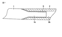
図7に、接着剤Sの厚さ分だけ傾斜して固着した状態を示すように、接着剤Sの厚さが薄くなった部分は、接着力が不足する。この場合には、先側部1が大きく撓んだ際に、接着力の不足から剥離が生じる可能性がある。また、先側部1と後側部2との中心軸線が互いに傾斜することにより、穂先竿の中間部で曲がった状態となり、釣り操作を円滑に行うことが困難な場合も生じる。   As shown in FIG. 7 in a state where the adhesive S is inclined and fixed by the thickness of the adhesive S, the portion where the thickness of the adhesive S is thin is insufficient in adhesive strength. In this case, when the front side portion 1 is greatly bent, peeling may occur due to insufficient adhesive force. Moreover, when the center axis line of the front side part 1 and the rear side part 2 inclines mutually, it will be in the state bent in the intermediate part of the tip of a tip, and the case where it is difficult to perform fishing operation smoothly may arise.

本発明は、このような事情に基づいてなされたもので、中実構造の第1穂先部と管状構造の第2穂先部とを、安定した接着剤層を確保して安定した取付強度で継ぎ合わせた竿杆を有する釣り竿を提供することを目的とする。   The present invention has been made based on such circumstances, and the first tip portion having a solid structure and the second tip portion having a tubular structure are joined to each other with a stable adhesive strength while securing a stable adhesive layer. An object is to provide a fishing rod having a combined rod.

上記目的を達成する本発明の釣り竿は、中実構造の第1穂先部と管状構造に形成した第2穂先部とを備え、この第2穂先部の先端に開口する嵌合孔に、前記第1穂先部から後方に突出する嵌合部を嵌合し、第1穂先部と第2穂先部とを一体構造に継ぎ合わせて形成した竿杆を有する釣り竿であって、前記嵌合部に、前記嵌合孔の内周面に直接接触する膨出部と、前記内周面との間に接着剤層を形成する接着部とを形成したことを特徴とする。   The fishing rod of the present invention that achieves the above object includes a first tip portion having a solid structure and a second tip portion formed in a tubular structure, and the fitting hole that opens at the tip of the second tip portion includes the first tip portion. A fishing rod having a rod formed by fitting a fitting portion projecting backward from one tip portion and joining the first tip portion and the second tip portion into an integrated structure, A bulging portion that directly contacts the inner peripheral surface of the fitting hole and an adhesive portion that forms an adhesive layer between the inner peripheral surface and the inner peripheral surface are formed.

前記膨出部は、軸方向に間隔をおいた複数の位置に形成してもよい。   The bulging portion may be formed at a plurality of positions spaced in the axial direction.

また、前記膨出部は、第1穂先部と別部材で形成することも可能である。   In addition, the bulging portion can be formed as a separate member from the first tip portion.

本発明の釣り竿によると、第1穂先部の嵌合部に形成した膨出部が、第2穂先部の嵌合孔の内周面に接触することにより、この嵌合部の接着部と嵌合孔の内周面との間に、接着剤がしごかれることなく、周面に所要の厚さの接着剤層が形成され、これにより、中実構造の第1穂先部と管状構造の第2穂先部とを、安定した接着剤層を確保して安定した取付強度で継ぎ合わせた竿杆を有する釣り竿が提供される。   According to the fishing rod of the present invention, the bulging portion formed in the fitting portion of the first tip portion comes into contact with the inner peripheral surface of the fitting hole of the second tip portion. An adhesive layer having a required thickness is formed on the peripheral surface without squeezing the adhesive between the inner peripheral surface of the joint hole, and thereby, the first tip portion of the solid structure and the tubular structure are formed. A fishing rod having a rod that joins the second tip portion with a stable attachment strength while securing a stable adhesive layer is provided.

この膨出部が軸方向に間隔をおいて複数の位置に形成される場合には、嵌合孔の内周面と接着部の外周面との間に均一な厚さの接着剤層を形成することができる。   When this bulging part is formed at a plurality of positions at intervals in the axial direction, an adhesive layer having a uniform thickness is formed between the inner peripheral surface of the fitting hole and the outer peripheral surface of the adhesive part. can do.

また、膨出部を第1穂先部と別部材で形成することにより、第2穂先部に応じて適宜の材質又は大きさとすることができる。   Moreover, it can be set as a suitable material or magnitude | size according to a 2nd tip part by forming a bulging part with a 1st tip part and another member.

図1は、本発明の好ましい実施形態による釣竿10を示す。   FIG. 1 shows a fishing rod 10 according to a preferred embodiment of the present invention.

この釣竿10は、振り出し式の例えば磯上物竿として形成してあり、穂先側の複数の竿杆を順に収納可能な最も大径の元側竿杆12にリールシート14を設け、このリールシート14に魚釣用リール8を取付けてある。この釣竿10には、竿管の外面に釣り糸が付着するのを防止する釣糸ガイド6が、魚釣用リール8と同じ側で、釣竿10の穂先に向けて所定間隔をおいて固定され、竿先にはトップガイド6aが取付けられている。このような釣糸ガイド6の個数および配置位置は、図示の例に限らず、任意に設定することが可能である。   The fishing rod 10 is formed as a swing-out type rod, for example, and a reel sheet 14 is provided on the largest-side rod 12 capable of sequentially storing a plurality of rods on the tip side. A fishing reel 8 is attached. A fishing line guide 6 for preventing the fishing line from adhering to the outer surface of the rod is fixed to the fishing rod 10 on the same side as the fishing reel 8 at a predetermined interval toward the tip of the fishing rod 10. A top guide 6a is attached to the tip. The number and arrangement position of such fishing line guides 6 are not limited to the illustrated example, and can be arbitrarily set.

このような釣竿10は、振出し式に限らず、いんろう継ぎ、並継ぎあるいは逆並継ぎ等の適宜の継ぎ形式のものであってもよい。また、複数の竿杆から形成するだけでなく、1本の竿杆でのみ形成してもよい。   Such a fishing rod 10 is not limited to a swing-out type, and may be of an appropriate joint type such as a brazing joint, a parallel joint or a reverse parallel joint. Moreover, you may form not only from several wrinkles but only with one wrinkle.

この釣り竿10の最も先端に配置した穂先竿16は、中実構造の第1穂先部と管状構造に形成した第2穂先部とを一体構造に継ぎ合わせた竿杆で形成してあり、この第1穂先部の先端にトップガイド6aが固定される。穂先竿16の先側の第1穂先部を中実構造に形成することにより、魚の引き等で大きく撓むことができると共に、釣り糸を介して微細な魚信を伝達することができる。   The tip 16 arranged at the foremost end of the fishing rod 10 is formed by a rod in which a solid first structure and a second structure formed in a tubular structure are joined together. A top guide 6a is fixed to the tip of one tip. By forming the first tip portion on the tip side of the tip rod 16 in a solid structure, it can be greatly bent by pulling fish or the like, and a fine fish belief can be transmitted through a fishing line.

図2に拡大して示すように、本実施形態の穂先竿16を形成する竿杆は、中実構造の第1穂先部20と管状構造に形成した第2穂先部30とを一体構造に継ぎ合わせて形成してある。この第2穂先部30は、強化繊維に合成樹脂を含浸させた繊維強化プリプレグ(FRP)シートを芯金に巻回した後、硬化、脱芯等の通常の工程を経て形成される。また、中実構造の第1穂先部20は、好適な単一材料で形成した中実体で形成し、または、中実体の周部に繊維強化樹脂層を形成した構造であってもよい。なお、第1穂先部20は、繊維強化樹脂に代え、その全体又は一部を、例えば超弾性合金等の適宜の金属材料で形成することも可能である。   As shown in an enlarged view in FIG. 2, the hook forming the tip hook 16 of the present embodiment has a solid structure of the first tip part 20 and the second tip part 30 formed in a tubular structure in an integrated structure. They are formed together. The second tip portion 30 is formed through a normal process such as curing and decentering after a fiber reinforced prepreg (FRP) sheet in which a reinforcing fiber is impregnated with a synthetic resin is wound around a cored bar. Moreover, the 1st tip part 20 of a solid structure may be formed with the solid body formed with the suitable single material, or the structure which formed the fiber reinforced resin layer in the peripheral part of the solid body. In addition, it replaces with fiber reinforced resin and the 1st tip part 20 can also form the whole or one part with appropriate metal materials, such as a superelastic alloy, for example.

第1穂先部20は、第2穂先部30と共に穂先竿16の外周面を形成する本体部22と、この本体部22の元側の後方端から後方に向けて突出する嵌合部24とを有する。また、第2穂先部30は軸方向に貫通する内孔32を有し、第1穂先部20の嵌合部24が嵌合する嵌合孔34が先端側に開口させて形成される。   The first tip portion 20 includes a main body portion 22 that forms the outer peripheral surface of the tip tip 16 together with the second tip portion 30, and a fitting portion 24 that protrudes rearward from the rear end on the original side of the main body portion 22. Have. Moreover, the 2nd tip part 30 has the inner hole 32 penetrated to an axial direction, and the fitting hole 34 with which the fitting part 24 of the 1st tip part 20 fits is opened and formed in the front end side.

第2穂先部30の先端に開口する嵌合孔34は、先端側に拡径するテーパ部34aと、このテーパ部34aの後方端に連続する円筒状部34bとを有し、本実施形態の円筒状部34bは内孔32の一部すなわち同径でかつ連続した内周面で形成されている。このテーパ部34aは、適宜の傾斜角で形成することができるが、第1穂先部20の本体部22の外周面との間に大きな段差が形成されるのを防止し、剛性を緩やかに変化させるために、中心軸線に対してテーパ率で20〜80/1000程度の角度に形成することが好ましい。   The fitting hole 34 that opens at the tip of the second tip 30 has a tapered portion 34a that expands toward the tip, and a cylindrical portion 34b that continues to the rear end of the tapered portion 34a. The cylindrical portion 34b is formed by a part of the inner hole 32, that is, the same diameter and a continuous inner peripheral surface. The tapered portion 34a can be formed with an appropriate inclination angle, but prevents a large step from being formed between the outer peripheral surface of the main body portion 22 of the first tip 20 and gradually changes the rigidity. Therefore, it is preferable to form the taper at an angle of about 20 to 80/1000 with respect to the central axis.

一方、第1穂先部20の嵌合部24は、円筒状の本体部22から後方に向けて縮径するテーパ部24aと、このテーパ部24aの後方端から後方に延びる円筒状部24bと、この円筒状部24bの後方端に配置された膨出部24cとを有する。テーパ部24aは、嵌合孔34の先端側に位置するテーパ部34aとほぼ同じ傾斜角で形成され、円筒状部24bは、嵌合孔32の円筒状部34bの内周面よりも僅かに小径に形成され、膨出部24cは、この円筒状部34bの内周面と同径に形成される。この円筒状部24bは、嵌合孔34の円筒状部34bの内周面よりも0.05〜0.3mmの範囲で、好ましくは0.10mm程度小さな内径を有し、この円筒状部34bの内周面との間に、接着剤層40を形成するための環状スペースを形成する。円筒状部24bの外径をこのように形成することにより、嵌合孔34内に挿入する嵌合部24の深さを調節し、嵌合部24のテーパ面24aと嵌合孔34のテーパ面34aとの間にも、同様な厚さの接着剤層40を形成することができる。   On the other hand, the fitting portion 24 of the first tip portion 20 includes a tapered portion 24a that decreases in diameter from the cylindrical main body portion 22 toward the rear, and a cylindrical portion 24b that extends rearward from the rear end of the tapered portion 24a. And a bulging portion 24c disposed at the rear end of the cylindrical portion 24b. The tapered portion 24 a is formed at substantially the same inclination angle as the tapered portion 34 a located on the distal end side of the fitting hole 34, and the cylindrical portion 24 b is slightly more than the inner peripheral surface of the cylindrical portion 34 b of the fitting hole 32. The bulging portion 24c is formed to have a small diameter and the same diameter as the inner peripheral surface of the cylindrical portion 34b. The cylindrical portion 24b has an inner diameter in the range of 0.05 to 0.3 mm, preferably about 0.10 mm, smaller than the inner peripheral surface of the cylindrical portion 34b of the fitting hole 34. The cylindrical portion 34b An annular space for forming the adhesive layer 40 is formed between the inner circumferential surface and the inner circumferential surface. By forming the outer diameter of the cylindrical portion 24b in this way, the depth of the fitting portion 24 inserted into the fitting hole 34 is adjusted, and the tapered surface 24a of the fitting portion 24 and the taper of the fitting hole 34 are adjusted. An adhesive layer 40 having a similar thickness can be formed between the surface 34a.

このように形成した第1穂先部20と第2穂先部30とを一体的に継ぎ合わせる際は、第1穂先部20の嵌合部24のテーパ部24aおよび円筒状部24bの外周に好適な接着剤を塗布しておく。この接着剤は、円筒状部24b上で、少なくとも膨出部24cの外周面と等しくなる厚さに形成する。   When integrally joining the first tip portion 20 and the second tip portion 30 thus formed, it is suitable for the outer periphery of the tapered portion 24a and the cylindrical portion 24b of the fitting portion 24 of the first tip portion 20. Apply adhesive. This adhesive is formed on the cylindrical portion 24b so as to have a thickness at least equal to the outer peripheral surface of the bulging portion 24c.

この後、挿入部20の嵌合部24を、後方端すなわち嵌合部24の後端に位置する膨出部24cから、第2穂先部30の嵌合孔34内に挿入する。膨出部24cは、嵌合孔30の先端に位置するテーパ部34aにより、円筒状部34bまで案内される。更に、第1穂先部20を後方に押圧すると、膨出部24cがこの円筒状部34bの内周面に沿って案内されつつ後方に押し込まれ、嵌合部24の円筒状部24bの外周には、嵌合孔34の円筒状部34bの内周面との間に、全周にわたって一定の径方向寸法を有する間隙が確保される。円筒状部24bの外周部に塗布された接着剤が嵌合孔34の円筒状部34bの先端側でしごき取られ、周方向に沿って不均一な厚さとなるのが防止される。   Thereafter, the fitting portion 24 of the insertion portion 20 is inserted into the fitting hole 34 of the second tip portion 30 from the bulging portion 24 c located at the rear end, that is, the rear end of the fitting portion 24. The bulging portion 24 c is guided to the cylindrical portion 34 b by the tapered portion 34 a located at the tip of the fitting hole 30. Further, when the first tip portion 20 is pressed rearward, the bulging portion 24c is pushed backward while being guided along the inner peripheral surface of the cylindrical portion 34b, and the outer periphery of the cylindrical portion 24b of the fitting portion 24 is pushed. Is secured between the inner peripheral surface of the cylindrical portion 34b of the fitting hole 34 and having a certain radial dimension over the entire circumference. The adhesive applied to the outer peripheral portion of the cylindrical portion 24b is squeezed off at the distal end side of the cylindrical portion 34b of the fitting hole 34, thereby preventing uneven thickness along the circumferential direction.

そして、第1穂先部20の本体部22の後端と、第2穂先部30の先端との間に所要幅の環状間隙35が形成された状態に保持することにより、テーパ部24a,34a間にも、円筒状部24b,34b間と同様な間隙が形成され、全周にわたって均等な厚さの接着剤層40が形成される。この接着剤層40が硬化されることにより、一定の取付強度で一体構造に継ぎ合わされた1本の竿杆からなる穂先竿16が形成される。   And by hold | maintaining in the state in which the cyclic | annular gap | interval 35 of required width was formed between the rear end of the main-body part 22 of the 1st tip part 20, and the front-end | tip of the 2nd tip part 30, between taper part 24a, 34a In addition, a gap similar to that between the cylindrical portions 24b and 34b is formed, and the adhesive layer 40 having a uniform thickness is formed over the entire circumference. By curing the adhesive layer 40, the tip ridge 16 composed of a single heel joined to the integrated structure with a fixed mounting strength is formed.

本実施形態では、第1穂先部20の嵌合部24は、これらのテーパ部24aおよび円筒状部24bが第2穂先部30に接着剤層40を介して接着固定する接着部として機能し、更に、膨出部24cが嵌合孔34の内周面に沿って円筒状部24bの外周側に一定の間隙を確保しつつ案内する案内部として機能する。この案内部としての機能を発揮させるために、膨出部24cの軸方向長さは、例えば嵌合部24の長さに対して0.5〜20%程度に形成することが好ましい。   In the present embodiment, the fitting portion 24 of the first tip portion 20 functions as an adhesive portion in which the tapered portion 24a and the cylindrical portion 24b are bonded and fixed to the second tip portion 30 via the adhesive layer 40, Further, the bulging portion 24 c functions as a guide portion that guides the outer circumferential side of the cylindrical portion 24 b along the inner circumferential surface of the fitting hole 34 while ensuring a certain gap. In order to exhibit the function as the guide portion, it is preferable that the length in the axial direction of the bulging portion 24 c is, for example, about 0.5 to 20% with respect to the length of the fitting portion 24.

したがって上述の実施形態によれば、第1穂先部20の嵌合部24に形成した膨出部24cが、第2穂先部30の嵌合孔34の円筒状部34cの内周面に接触することにより、この嵌合部24の接着部であるテーパ部24aおよび円筒状部24bと嵌合孔34のテーパ部34aおよび円筒状部34bの内周面との間に、所要の厚さの接着剤層40がその全周にわたってほぼ一定の厚さを有し、これにより、中実構造の第1穂先部20と管状構造の第2穂先部30とを、安定した接着剤層40を確保して安定した取付強度で継ぎ合わせた竿杆で形成された穂先竿16を有する釣り竿10が提供される。   Therefore, according to the above-described embodiment, the bulging portion 24 c formed in the fitting portion 24 of the first tip portion 20 contacts the inner peripheral surface of the cylindrical portion 34 c of the fitting hole 34 of the second tip portion 30. As a result, the taper portion 24a and the cylindrical portion 24b, which are the bonding portions of the fitting portion 24, and the taper portion 34a and the inner peripheral surface of the cylindrical portion 34b of the fitting hole 34 are bonded to each other with a required thickness. The agent layer 40 has a substantially constant thickness over the entire circumference thereof, thereby securing the stable adhesive layer 40 between the first tip part 20 having a solid structure and the second tip part 30 having a tubular structure. There is provided a fishing rod 10 having a tip rod 16 formed of rods spliced together with stable mounting strength.

図3は、他の実施形態による穂先竿16Aを示す。なお、以下に示す種々の実施形態あるいは変形例は、基本的には上述の実施形態と同様であるため、同様な部材には同様な符号を付し、その詳細な説明を省略する。   FIG. 3 shows a tip 16A according to another embodiment. Since various embodiments or modifications shown below are basically the same as those in the above-described embodiment, similar members are denoted by the same reference numerals, and detailed description thereof is omitted.

図3に示す実施形態は、膨出部24cが円筒状部24bの後端と前端との軸方向に間隔をおいた2つの位置に形成してある。   In the embodiment shown in FIG. 3, the bulging portion 24c is formed at two positions spaced apart in the axial direction between the rear end and the front end of the cylindrical portion 24b.

この場合には、上述の実施形態と同様な作用効果に加え、嵌合部24を嵌合孔34内に挿入する際に、この嵌合部24の傾きを防止することができ、円筒状部24b,34b間に、全周にわたって径方向寸法が一定の環状間隙を確保すると共に、第2穂先部30の中心軸線に対する第1穂先部20の中心軸線の傾きを防止し、双方の中心軸線を同一線上に保持することができる。なお、このような膨出部24cは、2つの位置に限らず、3つ以上の位置であってもよい。この場合には、膨出部24cの全体の軸方向寸法を短くすることもできる。   In this case, in addition to the same effects as those of the above-described embodiment, when the fitting portion 24 is inserted into the fitting hole 34, the fitting portion 24 can be prevented from tilting, and the cylindrical portion can be prevented. An annular gap having a constant radial dimension is secured between 24b and 34b, and the inclination of the center axis of the first tip 20 with respect to the center axis of the second tip 30 is prevented. Can be held on the same line. Such a bulging portion 24c is not limited to two positions, and may be three or more positions. In this case, the overall axial dimension of the bulging portion 24c can be shortened.

図4に示す実施形態では穂先竿16Bの嵌合部24に形成される膨出部24cが、この第1穂先部20とは別個に形成されたキャップ部材26で形成してある。このキャップ部材26は、嵌合孔34の円筒状部34bの内径に等しい外径を有し、円筒状部24bの後端に嵌合される。   In the embodiment shown in FIG. 4, the bulging portion 24 c formed in the fitting portion 24 of the tip 16 b is formed by a cap member 26 formed separately from the first tip 20. The cap member 26 has an outer diameter equal to the inner diameter of the cylindrical portion 34b of the fitting hole 34, and is fitted to the rear end of the cylindrical portion 24b.

このキャップ部材26は、嵌合孔34内に挿入する際に双方の中心軸線を同軸上に維持できるものであればよく、例えば合成樹脂、合成ゴム、金属等で形成することができる。   The cap member 26 only needs to be able to maintain both central axes coaxially when inserted into the fitting hole 34, and can be formed of, for example, synthetic resin, synthetic rubber, metal, or the like.

このように、膨出部24cを第1穂先部20とは別部材で形成することにより、第2穂先部30を形成する材質に応じて適宜の材質又は大きさとすることができる。   Thus, by forming the bulging portion 24 c as a member different from the first tip portion 20, it is possible to make the material or size appropriate for the material forming the second tip portion 30.

なお、図示のキャップ部材26は、周壁部の後端を閉じた有底構造に形成してあるが、嵌合部24上で移動が阻止できるものであれば、このような端壁を省略して両端を開口させた円筒状又はリング状に形成してもよい。この場合には、円筒状部24bの中間部位にも装着することができる。   Although the illustrated cap member 26 is formed in a bottomed structure in which the rear end of the peripheral wall portion is closed, such an end wall is omitted if it can be prevented from moving on the fitting portion 24. It may be formed in a cylindrical shape or a ring shape with both ends opened. In this case, it can be attached to an intermediate portion of the cylindrical portion 24b.

図5に示す穂先竿16Cは、膨出部24cが、円筒状部24bの後端面に固定した栓体28で形成してある。この栓体28は、先端側から突出する突起28aを、円筒状部24bの後端面の中心位置に形成した凹部25に嵌合させて固定してある。キャップ部材26と同様に、嵌合孔34内に挿入する際に双方の中心軸線を同軸上に維持できるものであれば、第1穂先部20又は第2穂先部30の材質に応じて、例えば合成樹脂、合成ゴム、金属等の好適な材料で形成することができる。   The tip 16C shown in FIG. 5 has a bulging portion 24c formed of a plug 28 fixed to the rear end surface of the cylindrical portion 24b. This plug body 28 is fixed by fitting a projection 28a protruding from the tip side into a recess 25 formed at the center position of the rear end surface of the cylindrical portion 24b. Similar to the cap member 26, if it can maintain both the central axes coaxially when inserted into the fitting hole 34, depending on the material of the first tip portion 20 or the second tip portion 30, for example, It can be formed of a suitable material such as synthetic resin, synthetic rubber, or metal.

以上、図に示す種々の実施形態および変形例について個々に説明してきたが、本発明はいずれかの実施形態あるいは変形例に限定されるものではなく、様々な用途に応じて適宜に変更しあるいは組合せることが可能である。例えば、図4に示すキャップ部材26を図2および図3に示す実施形態の嵌合部24に用いることも可能であり、図5に示す栓体28についても同様である。   The various embodiments and modifications shown in the drawings have been individually described above, but the present invention is not limited to any of the embodiments or modifications, and can be appropriately changed according to various applications. It is possible to combine them. For example, the cap member 26 shown in FIG. 4 can be used for the fitting portion 24 of the embodiment shown in FIGS. 2 and 3, and the same applies to the plug 28 shown in FIG. 5.

本発明の好ましい実施形態による釣り竿の全体を示す説明図。Explanatory drawing which shows the whole fishing rod by preferable embodiment of this invention. 図1に示す釣り竿の穂先竿の継ぎ部の断面を示し、(A)は長手方向の部分断面図、(B)は(A)のB−B線に沿う断面図、(C)はC−Cに沿う断面図。1 shows a cross-section of a spear of a fishing rod shown in FIG. 1, (A) is a partial cross-sectional view in the longitudinal direction, (B) is a cross-sectional view taken along line BB in (A), and (C) is C- Sectional drawing which follows C. FIG. 他の実施形態による穂先竿の釣り竿の継ぎ部の部分断面図。The fragmentary sectional view of the joint part of the fishing rod of the tip rod by other embodiment. 更に他の実施形態による穂先竿の図3と同様な部分断面図。Furthermore, the fragmentary sectional view similar to FIG. 3 of the spike tip by other embodiment. 更に他の実施形態による穂先竿の図3と同様な部分断面図。Furthermore, the fragmentary sectional view similar to FIG. 3 of the spike tip by other embodiment. 従来の穂先竿の継ぎ工程を示す説明図。Explanatory drawing which shows the conventional splicing process of a spike. 図6に示す工程で継いだ穂先竿の継ぎ部の部分断面図。FIG. 7 is a partial cross-sectional view of a joint portion of a spikelet spliced in the process shown in FIG. 6.

符号の説明Explanation of symbols

10…釣り竿、16…穂先竿(竿杆)、20…第1穂先部、24…嵌合部、24b…円筒状部(接着部)、24c…膨出部、30…第2穂先部、34…嵌合孔、34b…円筒状部、40…接着剤層。   DESCRIPTION OF SYMBOLS 10 ... Fishing rod, 16 ... Ear tip (竿 杆), 20 ... First tip part, 24 ... Fitting part, 24b ... Cylindrical part (adhesion part), 24c ... Expansion part, 30 ... Second tip part, 34 ... fitting hole, 34b ... cylindrical part, 40 ... adhesive layer.

Claims (3)

中実構造の第1穂先部と管状構造に形成した第2穂先部とを備え、この第2穂先部の先端に開口する嵌合孔に、前記第1穂先部から後方に突出する嵌合部を嵌合し、第1穂先部と第2穂先部とを一体構造に継ぎ合わせて嵌合領域を形成した竿杆を有する釣り竿であって、
前記嵌合部に、前記嵌合孔の内周面に直接接触する膨出部と、前記嵌合領域の範囲で前記膨出部の外径よりも小径に形成されて前記内周面との間に接着剤層を形成する接着部とを形成したことを特徴とする釣り竿。
A fitting portion that includes a first tip portion having a solid structure and a second tip portion formed in a tubular structure, and that protrudes rearward from the first tip portion into a fitting hole that opens at a tip of the second tip portion. Is a fishing rod having a rod that forms a fitting region by joining the first tip portion and the second tip portion into an integral structure,
The bulging portion that directly contacts the inner peripheral surface of the fitting hole in the fitting portion, and the inner peripheral surface that is formed with a smaller diameter than the outer diameter of the bulging portion in the range of the fitting region. A fishing rod having an adhesive portion between which an adhesive layer is formed.
前記膨出部は、軸方向に間隔をおいた複数の位置に形成されることを特徴とする請求項1に記載の釣り竿。   The fishing rod according to claim 1, wherein the bulging portions are formed at a plurality of positions spaced in the axial direction. 前記膨出部は、第1穂先部と別部材で形成されることを特徴とする請求項1又は2に記載の釣り竿。   The fishing rod according to claim 1 or 2, wherein the bulging portion is formed of a member separate from the first tip portion.
JP2008021923A 2008-01-31 2008-01-31 Fishing rod Withdrawn JP2009178131A (en)

Priority Applications (1)

Application Number Priority Date Filing Date Title
JP2008021923A JP2009178131A (en) 2008-01-31 2008-01-31 Fishing rod

Applications Claiming Priority (1)

Application Number Priority Date Filing Date Title
JP2008021923A JP2009178131A (en) 2008-01-31 2008-01-31 Fishing rod

Publications (1)

Publication Number Publication Date
JP2009178131A true JP2009178131A (en) 2009-08-13

Family

ID=41032597

Family Applications (1)

Application Number Title Priority Date Filing Date
JP2008021923A Withdrawn JP2009178131A (en) 2008-01-31 2008-01-31 Fishing rod

Country Status (1)

Country Link
JP (1) JP2009178131A (en)

Cited By (4)

* Cited by examiner, † Cited by third party
Publication number Priority date Publication date Assignee Title
CN103651287A (en) * 2012-08-31 2014-03-26 古洛布莱株式会社 Rod tip section and fishing rod with the same
CN103782978A (en) * 2012-10-30 2014-05-14 古洛布莱株式会社 Rod tip segment and fishing rod with the same
CN103782977A (en) * 2012-10-30 2014-05-14 古洛布莱株式会社 Rod tip segment and fishing rod with the same
JP2018143199A (en) * 2017-03-08 2018-09-20 株式会社シマノ Fishing rod and ear tip rod body of the same

Cited By (6)

* Cited by examiner, † Cited by third party
Publication number Priority date Publication date Assignee Title
CN103651287A (en) * 2012-08-31 2014-03-26 古洛布莱株式会社 Rod tip section and fishing rod with the same
CN103782978A (en) * 2012-10-30 2014-05-14 古洛布莱株式会社 Rod tip segment and fishing rod with the same
CN103782977A (en) * 2012-10-30 2014-05-14 古洛布莱株式会社 Rod tip segment and fishing rod with the same
KR20190038786A (en) * 2012-10-30 2019-04-09 글로브라이드 가부시키가이샤 Fishing rod
KR102067622B1 (en) * 2012-10-30 2020-01-17 글로브라이드 가부시키가이샤 Fishing rod
JP2018143199A (en) * 2017-03-08 2018-09-20 株式会社シマノ Fishing rod and ear tip rod body of the same

Similar Documents

Publication Publication Date Title
WO2011052303A1 (en) Method for affixing endoscope curved section envelope
JP2009178131A (en) Fishing rod
JP2023040304A (en) writing instrument
JP2016214217A (en) Drawing type fishing rod
JP3865285B2 (en) fishing rod
CN1799351B (en) Sleeve connection type fish-pole
JP4547709B2 (en) fishing rod
JP2009178130A (en) Fishing rod
US20220378028A1 (en) Fishing rod
JP2001136872A (en) Fishing rod
JP2514517Y2 (en) fishing rod
JP2004305073A (en) Top rod
JP2016136926A (en) fishing rod
JP2009240179A (en) Tip section rod
JP2003284456A (en) Fishing rod
JP2005245352A (en) Fishing rod
JP6402073B2 (en) fishing rod
JP4932353B2 (en) Endoscope and repair method
JP2007006802A (en) Fishing rod
JP2023089369A (en) Top guide, and fishing rod attached with top guide
JP4418767B2 (en) Tip of fishing rod
JP2000354438A (en) Connecting structure for fishing rod body
JP2001275522A (en) Jointed type fishing rod
JP2016136927A (en) fishing rod
JP3942839B2 (en) fishing rod

Legal Events

Date Code Title Description
A300 Withdrawal of application because of no request for examination

Free format text: JAPANESE INTERMEDIATE CODE: A300

Effective date: 20110405