JP2009176871A - Heat sink and electric apparatus - Google Patents

Heat sink and electric apparatus Download PDF

Info

Publication number
JP2009176871A
JP2009176871A JP2008012650A JP2008012650A JP2009176871A JP 2009176871 A JP2009176871 A JP 2009176871A JP 2008012650 A JP2008012650 A JP 2008012650A JP 2008012650 A JP2008012650 A JP 2008012650A JP 2009176871 A JP2009176871 A JP 2009176871A
Authority
JP
Japan
Prior art keywords
refrigerant
heat sink
flow path
refrigerant flow
partition wall
Prior art date
Legal status (The legal status is an assumption and is not a legal conclusion. Google has not performed a legal analysis and makes no representation as to the accuracy of the status listed.)
Granted
Application number
JP2008012650A
Other languages
Japanese (ja)
Other versions
JP5084527B2 (en
Inventor
Masao Akiyoshi
雅夫 秋吉
Hirotoshi Maekawa
博敏 前川
Masaru Kobayashi
勝 小林
Seiji Ishibashi
誠司 石橋
Haruyuki Matsuo
治之 松尾
Current Assignee (The listed assignees may be inaccurate. Google has not performed a legal analysis and makes no representation or warranty as to the accuracy of the list.)
Mitsubishi Electric Corp
Original Assignee
Mitsubishi Electric Corp
Priority date (The priority date is an assumption and is not a legal conclusion. Google has not performed a legal analysis and makes no representation as to the accuracy of the date listed.)
Filing date
Publication date
Application filed by Mitsubishi Electric Corp filed Critical Mitsubishi Electric Corp
Priority to JP2008012650A priority Critical patent/JP5084527B2/en
Publication of JP2009176871A publication Critical patent/JP2009176871A/en
Application granted granted Critical
Publication of JP5084527B2 publication Critical patent/JP5084527B2/en
Active legal-status Critical Current
Anticipated expiration legal-status Critical

Links

Images

Landscapes

  • Cooling Or The Like Of Electrical Apparatus (AREA)
  • Cooling Or The Like Of Semiconductors Or Solid State Devices (AREA)

Abstract

<P>PROBLEM TO BE SOLVED: To provide a compact heat sink having higher cooling performance which can be assembled easily and also provide an electric apparatus including the same heat sink. <P>SOLUTION: The heat sink (10) is mounted to a heating element and cools the heating element. The heat sink includes: a housing 14 forming a first coolant flowing route 36 and a second coolant flowing route 28 adjacent to the first coolant flowing route 36; a separating wall 44 arranged between the first and second coolant flowing routes 36, 38 to separate the first and second coolant flowing routes 36, 38; and a plurality of first fins 40 protruded to the first coolant flowing route 36 and a plurality of second fins 42 protruded to the second coolant flowing route 38, both fins being integrally formed to the housing 14. <P>COPYRIGHT: (C)2009,JPO&INPIT

Description

本発明は、半導体デバイスなどの電気機器で発生する熱を放散するヒートシンク、またヒートシンクを備えた電気機器に関する。   The present invention relates to a heat sink that dissipates heat generated in an electric device such as a semiconductor device, and an electric device including the heat sink.

ヒートシンクは、機械装置又は電気装置などの発熱体を有する装置に取り付けられ、発熱体を有する装置から熱を奪って発熱体やその周辺部品の温度を下げるものである。そのために、ヒートシンクの一形態として、ハウジングの内部に冷媒を流通させるものが提案されている。このようなヒートシンクでは、ハウジングを介して発熱装置の熱が冷媒に放熱される。この放熱を促進するため、ハウジング内部にハウジングと一体的に複数のフィンを設け、冷媒とハウジングとの接触面積を実質的に増加させるものがある。   The heat sink is attached to a device having a heating element such as a mechanical device or an electrical device, and takes heat from the device having the heating element to lower the temperature of the heating element and its peripheral components. Therefore, as one form of the heat sink, one in which a refrigerant is circulated inside the housing has been proposed. In such a heat sink, the heat of the heat generating device is radiated to the refrigerant through the housing. In order to promote this heat dissipation, there are some which provide a plurality of fins integrally with the housing inside the housing to substantially increase the contact area between the refrigerant and the housing.

複数のフィンが設けられたハウジングは、熱伝達効率および生産効率の観点から、一体的に押し出し成型されることが好ましいが、押し出し成型では長いフィンを密にハウジング内に設けることは困難である。そこで、例えば、特許文献1には、複数の第1のフィンを櫛状に有する第1の押し出し部材と、第2のフィンを櫛状に有する第2の押し出し部材を、第1のフィンと第2のフィンを交互に配置して組み合わせ、第1及び第2のフィンの先端を他方の押し出し部材に形成した溝に圧入して締結する熱交換機が提案されている。特許文献1に記載の熱交換機では、隣接する第1のフィンと第2のフィンとの間に形成される複数の空間を冷媒の流路とすることによって、ヒートシンクに応用できる。
特開2002−26207号公報
The housing provided with a plurality of fins is preferably integrally molded from the viewpoint of heat transfer efficiency and production efficiency, but it is difficult to densely provide long fins in the housing by extrusion molding. Therefore, for example, Patent Document 1 discloses a first extruding member having a plurality of first fins in a comb shape, a second extruding member having a second fin in a comb shape, a first fin and a first fin. There has been proposed a heat exchanger in which two fins are alternately arranged and combined, and the tips of the first and second fins are press-fitted into a groove formed in the other pushing member and fastened. The heat exchanger described in Patent Document 1 can be applied to a heat sink by using a plurality of spaces formed between adjacent first fins and second fins as refrigerant flow paths.
JP 2002-26207 A

このように、特許文献1に記載の熱交換器に関する技術はヒートシンクにも応用可能であるが、全てのフィンの先端を他方の押し出し部材に形成した溝に圧入する作業は多くの時間を要することから、生産性が悪いという問題がある。   As described above, the technology related to the heat exchanger described in Patent Document 1 can also be applied to a heat sink, but it takes a lot of time to press fit the tips of all fins into the groove formed in the other pushing member. Therefore, there is a problem that productivity is bad.

そこで、本発明は、小型で、組立が容易で、しかも高い冷却性能を有するヒートシンク、およびそれを備えた電気機器を提供するものである。   Therefore, the present invention provides a heat sink that is small in size, easy to assemble, and has high cooling performance, and an electric device including the heat sink.

本発明は、発熱体に取り付けられ、前記発熱体を冷却するヒートシンクであって、第1の冷媒流路と前記第1の冷媒流路に隣接する第2の冷媒流路を形成するハウジングと、前記第1と第2の冷媒流路の間に配置され、前記第1と第2の冷媒流路を隔離する隔壁と、前記ハウジングに一体的に形成された、前記第1の冷媒流路に突出した複数の第1のフィンと前記第2の冷媒流路に突出した複数の第2のフィンとを備えたことを特徴とする。   The present invention is a heat sink that is attached to a heating element and cools the heating element, and a housing that forms a first refrigerant channel and a second refrigerant channel adjacent to the first refrigerant channel; A partition wall disposed between the first and second refrigerant flow paths and separating the first and second refrigerant flow paths; and the first refrigerant flow path formed integrally with the housing. A plurality of first fins projecting and a plurality of second fins projecting into the second refrigerant flow path are provided.

この発明によれば、ヒートシンクは、第1と第2の冷媒流路の間に隔壁を配置するという簡単な作業によって組み立てることができる。   According to this invention, the heat sink can be assembled by a simple operation of disposing the partition wall between the first and second refrigerant flow paths.

実施の形態1. Embodiment 1 FIG.

図1〜3を参照して実施の形態1のヒートシンクを説明する。図示するヒートシンク10は、発熱体12で発生する熱を放散するものである。発熱体12には種々の機器が考えられるが、実施の形態では、例えばインバータやコンバータを構成する半導体装置を発熱体として想定している。   The heat sink of Embodiment 1 is demonstrated with reference to FIGS. The illustrated heat sink 10 dissipates heat generated by the heating element 12. Although various devices can be considered as the heating element 12, in the embodiment, for example, a semiconductor device constituting an inverter or a converter is assumed as the heating element.

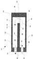
ヒートシンク10の構成を具体的に説明すると、ヒートシンク10は、伝熱性に優れた材料(好ましくは、金属材料)からなるハウジング14を有する。ハウジング14は、概略、中空の筒部16と、2つの蓋(第1の蓋18,第2の蓋20)を有する。筒部16は、直線状の中心軸22に沿って伸びる内空部24と、内空部24の両端に位置する端部開口部(第1の端部開口部26と第2の端部開口部28)を有し、これら端部開口部26,28が蓋18,20で塞がれている。実施の形態において、筒部16は横断面が四角形の外形を有するが、任意の外形断面を採り得る。また、内空部24は四角形の横断面を有するが、横断面は任意の形状を採り得る。   The configuration of the heat sink 10 will be specifically described. The heat sink 10 includes a housing 14 made of a material (preferably a metal material) having excellent heat transfer properties. The housing 14 generally has a hollow cylindrical portion 16 and two lids (a first lid 18 and a second lid 20). The cylindrical portion 16 includes an inner space portion 24 extending along the linear center axis 22 and end opening portions (first end opening portion 26 and second end opening portions) located at both ends of the inner space portion 24. Portion 28), and these end openings 26 and 28 are closed by lids 18 and 20, respectively. In the embodiment, the cylindrical portion 16 has a quadrangular outer shape in cross section, but may take any outer cross section. The inner space 24 has a rectangular cross section, but the cross section may take any shape.

具体的に、実施の形態では、筒部16は、中心軸を挟んで対向する下壁30と上壁32および左右の側壁34を有する。これらの壁に囲まれた内空部24は、中心軸22と平行に伸びる上下の冷媒通路(第1の冷媒通路又は下部冷媒通路36、第2の冷媒通路又は上部冷媒通路38)を有し、冷媒通路36,38のそれぞれに複数の放熱板(第1のフィン40、第2のフィン42)が配置されている。フィン40,42は、筒部16の下壁30、上壁32に一体的に形成されており、それぞれ他方の壁に向かって伸びている。実施の形態では、フィン40,42はそれぞれ、中心軸22と平行に、且つ、一方の端部開口部26から他方の端部開口部28の全長又はほぼ全長に亘って連続的に伸びている。実施の形態では、フィン40,42は等間隔に配置されているが、間隔は任意である。また、各フィン40,42の厚みはほぼ一定であるが、基端側(壁に近い端部)で厚く、末端側で薄くしてもよい。   Specifically, in the embodiment, the cylindrical portion 16 has a lower wall 30, an upper wall 32, and left and right side walls 34 that are opposed to each other with the central axis interposed therebetween. The inner space 24 surrounded by these walls has upper and lower refrigerant passages (first refrigerant passage or lower refrigerant passage 36, second refrigerant passage or upper refrigerant passage 38) extending in parallel with the central axis 22. A plurality of heat radiating plates (first fins 40, second fins 42) are disposed in each of the refrigerant passages 36, 38. The fins 40 and 42 are formed integrally with the lower wall 30 and the upper wall 32 of the tubular portion 16 and extend toward the other wall. In the embodiment, each of the fins 40 and 42 extends in parallel with the central axis 22 and continuously from the one end opening 26 over the entire length or almost the entire length of the other end opening 28. . In the embodiment, the fins 40 and 42 are arranged at equal intervals, but the intervals are arbitrary. Moreover, although the thickness of each fin 40,42 is substantially constant, you may make it thick at the base end side (end part near a wall), and thin at the terminal end side.

ヒートシンク10は、冷媒通路36,38を隔離する隔壁44を有する。実施の形態では、隔壁44は、フィン40、42の間に形成された空間に、第1の端部開口部26から挿入され、上下のフィン40、42によって実質的に上下に移動できない状態で支持されている。隔壁44の幅は、側壁34の間隔とほぼ等しいことが好ましい。隔壁44の厚さは、製造上の観点からは厚い方が好ましく、冷媒通路を広く確保するには薄い方が好ましい。そのため、これらの要素の他、複数の冷媒通路間の熱伝達などを考慮して、適宜、隔壁44の厚さを、決定してよい。隔壁44の長さは、図2に示すように、隔壁44の一端46が第1の端部開口部26に位置した状態で、隔壁44の他端48が第2の端部開口部28から所定の間隔をあけて離間し、これにより隔壁44の他端48と第2の蓋20との間に冷媒通路36,38を連通する連通路50を形成するように調整されている。   The heat sink 10 has a partition wall 44 that separates the refrigerant passages 36 and 38. In the embodiment, the partition wall 44 is inserted into the space formed between the fins 40 and 42 from the first end opening 26 and cannot move substantially vertically by the upper and lower fins 40 and 42. It is supported. The width of the partition wall 44 is preferably substantially equal to the interval between the side walls 34. The thickness of the partition wall 44 is preferably thicker from the viewpoint of manufacturing, and the thinner one is preferable for securing a wide refrigerant passage. Therefore, the thickness of the partition wall 44 may be appropriately determined in consideration of heat transfer between a plurality of refrigerant passages in addition to these elements. As shown in FIG. 2, the length of the partition wall 44 is such that one end 46 of the partition wall 44 is positioned in the first end opening 26 and the other end 48 of the partition wall 44 extends from the second end opening 28. The communication path 50 is adjusted to form a communication path 50 that communicates with the refrigerant paths 36 and 38 between the other end 48 of the partition wall 44 and the second lid 20.

このように、上下のフィン40,42で隔壁44を図示する位置に安定的に支持するために、隔壁44が位置する領域にあるフィン40,42の少なくとも一部は、隔壁44が筒部16に装着された状態でフィン40,42の末端が隔壁40の上面及び下面にそれぞれ接触する長さを有することが好ましい。   As described above, in order to stably support the partition wall 44 at the illustrated position by the upper and lower fins 40 and 42, at least a part of the fins 40 and 42 in the region where the partition wall 44 is located has the partition wall 44 formed of the cylindrical portion 16. It is preferable that the ends of the fins 40 and 42 have such a length that they are in contact with the upper surface and the lower surface of the partition wall 40 respectively.

このような構成を有する筒部16は、押し出し成型によって精度良く加工できる。当然、筒部16を上下に二分割し、2つの分割部分を別々に押し出し成型又は射出成型によって形成し、後に適宜連結手段で連結することもできる。   The cylindrical portion 16 having such a configuration can be processed with high accuracy by extrusion molding. Naturally, it is also possible to divide the cylindrical portion 16 into two parts in the upper and lower directions, separately form the two divided parts by extrusion molding or injection molding, and connect them later with appropriate connecting means.

図1,2に示すように、蓋18,20は、筒部16の端面形状に対応した大きさを有する板状の部材からなり、筒部16に隔壁44を装着した後ボルト等の固定手段で筒部16の端部に固定される。筒部16と蓋18,20の対向面に、環状のゴムリング等のシール手段を配置して密閉することが好ましい。蓋20は単なる板であるが、第1の端部開口部26を閉じる蓋18は、装着された状態で冷媒通路36,38にそれぞれ対応する場所に冷媒流入路(第1の冷媒通路)52、冷媒流出路(第2の冷媒通路)54を有する。   As shown in FIGS. 1 and 2, the lids 18 and 20 are made of a plate-like member having a size corresponding to the end face shape of the cylindrical portion 16, and a fixing means such as a bolt after the partition wall 44 is attached to the cylindrical portion 16. To be fixed to the end of the cylindrical portion 16. It is preferable that sealing means such as an annular rubber ring is disposed on the opposed surfaces of the cylindrical portion 16 and the lids 18 and 20 for sealing. The lid 20 is a simple plate, but the lid 18 that closes the first end opening 26 is installed in a refrigerant inflow passage (first refrigerant passage) 52 at a location corresponding to the refrigerant passages 36 and 38 respectively. And a refrigerant outflow passage (second refrigerant passage) 54.

以上のように構成されたヒートシンク10の使用時、図1に示すように、下壁30の外面と上壁32の外面の両方又はそれらのいずれか一方に、発熱体12である半導体装置が固定される。ヒートシンク10には、図示しない冷媒供給源から供給された冷媒56が冷媒流入路52を介して下部冷媒通路36に供給される。通常、冷媒56には液体(例えば、水)又は気体が使用される。下壁30及びフィン40は、下部の発熱体12から伝導した熱を、下部冷媒通路36を流れる冷媒56に放熱する。次に、冷媒56は、下部冷媒通路36の下流側端部で連通路50を介して上部冷媒通路38に移動し、冷媒流出路54に向かって逆方向に流れる。上壁32及びフィン42は、上壁32に取り付けた発熱体12から伝導した熱を、上部冷媒通路38を流れる冷媒56に放熱する。以上のように、ヒートシンク10は、発熱体12から伝導する熱を冷媒56に放熱し、これによって、発熱体12を冷却する。   When the heat sink 10 configured as described above is used, as shown in FIG. 1, the semiconductor device as the heating element 12 is fixed to both the outer surface of the lower wall 30 and the outer surface of the upper wall 32 or one of them. Is done. A refrigerant 56 supplied from a refrigerant supply source (not shown) is supplied to the heat sink 10 through the refrigerant inflow passage 52 to the lower refrigerant passage 36. Usually, a liquid (for example, water) or a gas is used for the refrigerant 56. The lower wall 30 and the fin 40 radiate the heat conducted from the lower heating element 12 to the refrigerant 56 flowing through the lower refrigerant passage 36. Next, the refrigerant 56 moves to the upper refrigerant path 38 via the communication path 50 at the downstream end of the lower refrigerant path 36 and flows in the opposite direction toward the refrigerant outflow path 54. The upper wall 32 and the fin 42 radiate the heat conducted from the heating element 12 attached to the upper wall 32 to the refrigerant 56 flowing through the upper refrigerant passage 38. As described above, the heat sink 10 dissipates the heat conducted from the heating element 12 to the refrigerant 56, thereby cooling the heating element 12.

以上のように、実施の形態1のヒートシンク10によれば、一つのハウジング14の中で流路を略U字状に折り返した長い冷媒流路が形成される。そのため、折り返すことなく例えば並列の二つの流路を一方向に冷媒を流す場合よりも、冷媒の流速が速くなり、高い冷却能力が得られる。また、ヒートシンク10は、押し出し成型又は射出成型された筒部16に隔壁44を挿入し、蓋18,20を取り付けるといった簡単な作業で組み立てられるので、製造に要する手間が格段と少ない。   As described above, according to the heat sink 10 of the first embodiment, a long refrigerant flow path is formed by folding the flow path in a substantially U shape in one housing 14. Therefore, for example, the flow rate of the refrigerant becomes faster and higher cooling capacity can be obtained than when the refrigerant flows in one direction through two parallel flow paths without being folded. Further, since the heat sink 10 is assembled by a simple operation of inserting the partition wall 44 into the extruded or injection-molded cylindrical portion 16 and attaching the lids 18 and 20, the labor required for manufacturing is remarkably reduced.

なお、吸熱前の冷媒56は吸熱後の冷媒56に比べて温度が低く、高い吸熱性を有する。したがって、図1に示すように、ヒートシンク10の上下に発熱体12を取り付ける場合、より低温の冷媒56が流れる下部冷媒通路36の近傍に発熱量の多い発熱体、または耐熱性能が低い装置を配置し、より高温の冷媒56が流れる上部冷媒通路38の近傍に発熱量の少ない発熱体、または耐熱性能が高い装置を配置してもよい。また、より多くの熱量を回収すべき発熱体を下部冷媒通路36の近傍に配置し、より少ない熱量を回収すべき発熱体を上部冷媒通路38の近傍に配置してもよい。さらに、以上の説明では、下部に冷媒流入路52、上部に冷媒流出路54を配置し、冷媒56を下部冷媒通路36から上部冷媒通路38に向かって流すものとしたが、逆に、上部冷媒流路38から下部冷媒流路36に向けて冷媒56を流してもよい。   In addition, the refrigerant | coolant 56 before heat absorption has a low temperature compared with the refrigerant | coolant 56 after heat absorption, and has high heat absorption. Therefore, as shown in FIG. 1, when the heating elements 12 are attached to the upper and lower sides of the heat sink 10, a heating element having a large amount of heat generation or a device having low heat resistance is disposed in the vicinity of the lower refrigerant passage 36 through which the cooler refrigerant 56 flows. However, a heating element with a small heat generation amount or a device with high heat resistance may be arranged in the vicinity of the upper refrigerant passage 38 through which the higher-temperature refrigerant 56 flows. In addition, a heating element that should recover a larger amount of heat may be disposed in the vicinity of the lower refrigerant passage 36, and a heating element that should recover a smaller amount of heat may be disposed in the vicinity of the upper refrigerant path 38. Furthermore, in the above description, the refrigerant inflow path 52 is disposed in the lower part, the refrigerant outflow path 54 is disposed in the upper part, and the refrigerant 56 flows from the lower refrigerant path 36 toward the upper refrigerant path 38. The refrigerant 56 may flow from the flow path 38 toward the lower refrigerant flow path 36.

上下いずれに冷媒流入路52、冷媒流出路54を配置するかは、冷媒の性質によって決めてもよい。例えば、気体冷媒を使用する場合、下部に冷媒流入路52、上部に冷媒流出路54を配置し、逆に、液体冷媒を使用する場合、上部に冷媒流入路52、下部に冷媒流出路54を配置してもよい。例えば、冷却能力の低い気体冷媒を使用する場合、吸熱して比重の軽くなった気体冷媒を効率良く排出するためには、吸熱前の気体冷媒を下部の冷媒流入路52から供給し、吸熱後の気体冷媒を上部の冷媒流出路54から排出することが好ましい。   Which of the refrigerant inflow path 52 and the refrigerant outflow path 54 is arranged above and below may be determined depending on the nature of the refrigerant. For example, when a gas refrigerant is used, the refrigerant inflow path 52 is disposed at the lower part and the refrigerant outflow path 54 is disposed at the upper part. Conversely, when liquid refrigerant is used, the refrigerant inflow path 52 is disposed at the upper part and the refrigerant outflow path 54 is disposed at the lower part. You may arrange. For example, when using a gas refrigerant having a low cooling capacity, in order to efficiently discharge the gas refrigerant that has absorbed heat and has a lighter specific gravity, the gas refrigerant before heat absorption is supplied from the lower refrigerant inflow passage 52, and after the heat absorption, It is preferable to discharge the gaseous refrigerant from the upper refrigerant outlet passage 54.

上述した実施の形態1のヒートシンク10は、種々改変可能である。   The heat sink 10 of the first embodiment described above can be variously modified.

実施の形態2. Embodiment 2. FIG.

実施の形態1では、下部冷媒通路36と上部冷媒通路38を連通する連通路50は、隔壁44の他端48を第2の蓋20から離間させることよって形成したが、隔壁44を第1の端部開口部26から第2の端部開口部28まで連続的に延在する長さとするとともに、隔壁44の第2の端部開口部28近傍に一つ又は複数の連通孔(円形又は矩形の孔、または流れの方向に沿って長いスロット)を形成し、この連通孔を通じて下部冷媒通路36から上部冷媒通路38に冷媒56を流してもよい。複数の連通孔は、冷媒通路の幅方向に均等に配置してもよいし、不均等に配置してもよい。また、連通孔は、隣接するフィン40の間を流れる冷媒56がより少ない抵抗を受けながら下部から上部の冷媒通路にスムーズに移動し、それによってより高い冷却性が得られるように、中心軸22と平行な方向(以下、「中心軸22方向」という。)から見たとき、隣接するフィン40の間に位置していることが好ましい。   In the first embodiment, the communication path 50 that connects the lower refrigerant path 36 and the upper refrigerant path 38 is formed by separating the other end 48 of the partition wall 44 from the second lid 20. The length continuously extends from the end opening 26 to the second end opening 28, and one or a plurality of communication holes (circular or rectangular) are formed in the vicinity of the second end opening 28 of the partition wall 44. Or a long slot along the flow direction), and the refrigerant 56 may flow from the lower refrigerant passage 36 to the upper refrigerant passage 38 through the communication hole. The plurality of communication holes may be arranged uniformly in the width direction of the refrigerant passage or may be arranged unevenly. Further, the communication hole smoothly moves from the lower part to the upper refrigerant passage while the refrigerant 56 flowing between the adjacent fins 40 receives less resistance, so that higher cooling performance can be obtained. It is preferably located between adjacent fins 40 when viewed from a direction parallel to the direction (hereinafter referred to as “the direction of the central axis 22”).

実施の形態3. Embodiment 3 FIG.

図4に示すように、蓋18には、冷媒流入路52から供給された冷媒56を横方向に出来るだけ均等に分散するために、冷媒流路36及びフィン40の上流側に位置する分流ヘッダ(凹部)58を形成してもよい。また、蓋18には、冷媒通路38の全域(幅方向の全域)から冷媒流出路54に効率良く冷媒56を回収するために、冷媒通路38の及びフィン42の下流側に位置する合流ヘッダ(凹部)59を形成してもよい。このような構成を採用することにより、冷媒56の圧力損失が低下し、ポンプ動力一定の場合は冷媒56の流量が増加し、引いてはヒートシンク10の冷却能力を上げることができる。当然のことであるが、分流ヘッダ58と合流ヘッダ59の間には蓋18の一部(隔壁部60)が存在し、冷媒通路36,38の間を遮断している。なお、分流ヘッダと合流ヘッダは、フィン40,42を第1の端部開口部26から後退させることによって形成することもできる。   As shown in FIG. 4, in the lid 18, in order to disperse the refrigerant 56 supplied from the refrigerant inflow passage 52 as evenly as possible in the lateral direction, the shunt header located upstream of the refrigerant flow path 36 and the fins 40. (Recess) 58 may be formed. In addition, the lid 18 has a merge header (on the downstream side of the refrigerant passage 38 and on the downstream side of the fins 42) in order to efficiently collect the refrigerant 56 from the entire region of the refrigerant passage 38 (the entire region in the width direction) to the refrigerant outflow passage 54. (Recess) 59 may be formed. By adopting such a configuration, the pressure loss of the refrigerant 56 is reduced, the flow rate of the refrigerant 56 is increased when the pump power is constant, and the cooling capacity of the heat sink 10 can be increased. As a matter of course, a part of the lid 18 (partition wall portion 60) exists between the diversion header 58 and the merge header 59 and blocks the refrigerant passages 36 and 38. The shunt header and the merge header can also be formed by retracting the fins 40 and 42 from the first end opening 26.

実施の形態4. Embodiment 4 FIG.

図5,6に示すように、蓋18の隔壁部60を筒体内部に向けて突出して突出隔壁部62を形成するとともに、この突出隔壁部62に横方向に伸びる溝64を形成し、隔壁44の対応する箇所には溝64に嵌め込まれる突条66を形成し、隔壁44が装着された筒部16に蓋18を取り付ける際、突条66を溝64に嵌め込むようにしてもよい。この場合、隔壁44と蓋18の間のシール性が更に良くなる。この変形例において、突出隔壁部62は必ずしも必要ではなく、例えば図7に示すように、隔壁部60に突条66が嵌め込まれる溝67を形成してもよい。   As shown in FIGS. 5 and 6, the partition wall 60 of the lid 18 protrudes toward the inside of the cylindrical body to form a protruding partition wall 62, and a groove 64 extending in the lateral direction is formed in the protruding partition wall 62. A protrusion 66 to be fitted into the groove 64 may be formed at a corresponding position of 44, and the protrusion 66 may be fitted into the groove 64 when the lid 18 is attached to the cylinder portion 16 to which the partition wall 44 is attached. In this case, the sealing performance between the partition wall 44 and the lid 18 is further improved. In this modification, the protruding partition wall 62 is not necessarily required, and a groove 67 into which the protrusion 66 is fitted in the partition wall 60 may be formed as shown in FIG.

実施の形態5. Embodiment 5 FIG.

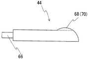
冷媒通路を流れる冷媒は、フィンの基端から末端に向かう方向に拡散し、例えば、第1の冷媒通路ではフィンの基端近傍を通過した冷媒を第2の冷媒通路ではフィンの末端側を流れるように、少なくとも一部を入れ替えることによって冷媒の吸熱能力を最大限に活用することが好ましい。そのため、例えば、図8に示すように、隔壁44は、冷媒流路36,38を連通する連通路50の近傍であって第2の冷媒流路38の上流側端部に、冷媒流路38に向かって突出して形成された四角形縦断面(中心軸22方向の横断面が四角形)の撹拌部68を有する。図示するように、撹拌部68は横方向に連続的に設けられてもよいし、図示しないが、横方向に間欠的に設けられてもよい。フィン42との干渉を避けるために、撹拌部68にはフィン42に対応する位置にフィン挿入スロット70を形成し、フィン42の末端をスロット70に挿入するようにしてもよい。撹拌部68の形状(縦断面)は図8に示すものに限定されるものでなく、例えば、図9に示す三角形、図10に示す円弧状であってもよい。   The refrigerant flowing in the refrigerant passage diffuses in the direction from the proximal end of the fin toward the distal end. For example, in the first refrigerant passage, the refrigerant that has passed near the proximal end of the fin flows in the second refrigerant passage on the distal end side of the fin. Thus, it is preferable to make maximum use of the heat absorption capacity of the refrigerant by replacing at least a part thereof. Therefore, for example, as shown in FIG. 8, the partition wall 44 is in the vicinity of the communication path 50 that communicates the refrigerant flow paths 36 and 38, and at the upstream end portion of the second refrigerant flow path 38. The stirring unit 68 has a quadrangular vertical section (a cross section in the direction of the central axis 22 is quadrangular) formed so as to protrude toward the center. As shown in the drawing, the stirring unit 68 may be provided continuously in the horizontal direction, or may be provided intermittently in the horizontal direction, although not shown. In order to avoid interference with the fins 42, the stirring portion 68 may be formed with fin insertion slots 70 at positions corresponding to the fins 42, and the ends of the fins 42 may be inserted into the slots 70. The shape (longitudinal section) of the stirring unit 68 is not limited to that shown in FIG. 8, and may be, for example, a triangle shown in FIG. 9 or an arc shape shown in FIG. 10.

このような撹拌部68を設けることにより、連通路50を通じて第2の冷媒通路38に移動した冷媒56は、第1の冷媒通路36でフィン末端側を通過した冷媒の一部が第2の冷媒通路38ではフィン基端側に移動し、逆に、第1の冷媒通路36でフィン基端側を通過した冷媒の一部が第2の冷媒通路38ではフィン末端側に移動することにより、温度が高いフィン基端部での熱交換が促進され、全体としてヒートシンク10の冷却能力が一段と向上する。   By providing such a stirring unit 68, the refrigerant 56 that has moved to the second refrigerant passage 38 through the communication passage 50 has a portion of the refrigerant that has passed through the fin end side in the first refrigerant passage 36 as the second refrigerant. In the passage 38, the refrigerant moves to the fin base end side, and conversely, a part of the refrigerant that has passed through the fin base end side in the first refrigerant passage 36 moves to the fin distal end side in the second refrigerant passage 38. The heat exchange at the fin base end portion having a high height is promoted, and the cooling capacity of the heat sink 10 is further improved as a whole.

実施の形態6. Embodiment 6 FIG.

ヒートシンク10の冷却能力を更に向上するために、図11に示すように、隔壁44の両面に棒状の乱流促進ピン72を設けてもよい。乱流促進ピン72は、流路での冷媒の流れを乱し、フィン40,42の周りでの温度境界層の発達を抑制する。当然、隔壁44を筒部16に装着する際に乱流促進ピン72がフィン40,42と干渉するのを防止するために、乱流促進ピン72は隣接するフィン40,40、42,42の間に位置するようにする。   In order to further improve the cooling capacity of the heat sink 10, rod-shaped turbulent flow promotion pins 72 may be provided on both surfaces of the partition wall 44 as shown in FIG. The turbulent flow promotion pin 72 disturbs the flow of the refrigerant in the flow path and suppresses the development of the temperature boundary layer around the fins 40 and 42. Naturally, in order to prevent the turbulent flow promotion pins 72 from interfering with the fins 40 and 42 when the partition wall 44 is attached to the cylindrical portion 16, the turbulent flow promotion pins 72 are arranged on the adjacent fins 40, 40, 42 and 42. Try to be in between.

乱流促進ピン72の間隔(中心軸22方向の間隔)、長さ、太さ、形状は、乱流促進ピン72の冷媒56の流れに対する抵抗、特にフィン40,42の周りでの冷媒の流れを考慮して決定する。例えば、乱流促進ピン72の太さ(径)は、隣接するフィン40又は42との間に、例えば約0.1mm〜1mm程度の隙間が確保されるように決定する。   The distance (interval in the direction of the central axis 22), the length, the thickness, and the shape of the turbulent flow promotion pins 72 are the resistance to the flow of the refrigerant 56 of the turbulent flow promotion pins 72, particularly the flow of the refrigerant around the fins 40 and 42. Determine in consideration of For example, the thickness (diameter) of the turbulent flow promotion pin 72 is determined so that a gap of, for example, about 0.1 mm to 1 mm is secured between the adjacent fins 40 or 42.

このように、フィン40,42の間に乱流促進ピン72を配置することにより、フィン40,42の表面付近に形成される温度境界層を乱し、フィンと冷媒の熱交換を促進し、ヒートシンク10の冷却性能をより向上することができる。図12に示すように、中心軸22と直交する方向に関して、乱流促進ピン72はフィン40,42の両側に接近し、隣接するフィンの間で隣接する乱流促進ピン72の間に出来るだけ大きな流路を確保することが好ましい。乱流促進ピン72をフィン間流路の中央付近に配置すると、フィンと冷媒との熱交換は促進される反面、冷媒の圧力損失が増大するためである。   Thus, by disposing the turbulent flow promotion pin 72 between the fins 40 and 42, the temperature boundary layer formed near the surface of the fins 40 and 42 is disturbed, and heat exchange between the fins and the refrigerant is promoted. The cooling performance of the heat sink 10 can be further improved. As shown in FIG. 12, the turbulence promoting pin 72 approaches both sides of the fins 40 and 42 in the direction orthogonal to the central axis 22, and between the adjacent turbulence promoting pins 72 as much as possible. It is preferable to secure a large flow path. If the turbulent flow promotion pin 72 is disposed near the center of the inter-fin flow path, heat exchange between the fin and the refrigerant is promoted, but the pressure loss of the refrigerant increases.

好適な乱流促進ピン72が横断面形状は、図13に示す三角形、図14に示す翼形状(翼の断面を有する形状)で、冷媒の流れる方向に関して、上流側から下流側に向かってフィン40,42に次第に接近する傾斜面74を有する。このような形状によれば、図の矢印方向に流れる冷媒が、フィン40,42の近傍でピンの前方傾斜面74によって偏向されると共にその速度を増し、フィン40,42の表面に勢いよく衝突する。その結果、フィン表面の温度境界層が効率良く破壊されることにより、フィンの熱交換能力が常に良好に維持される。また、傾斜面74の反対側では、冷媒56の流れに乱れが生じて、フィンから回収された熱が効率良く拡散される。   The preferred turbulent flow promotion pin 72 has a triangular cross section as shown in FIG. 13 and a wing shape (a shape having a cross section of the wing) as shown in FIG. 14, and fins from the upstream side to the downstream side in the refrigerant flow direction. An inclined surface 74 that gradually approaches 40 and 42 is provided. According to such a shape, the refrigerant flowing in the direction of the arrow in the figure is deflected by the forward inclined surface 74 of the pin in the vicinity of the fins 40 and 42 and increases its speed, and collides with the surfaces of the fins 40 and 42 vigorously. To do. As a result, the temperature boundary layer on the fin surface is efficiently destroyed, so that the heat exchange capability of the fin is always kept good. On the other side of the inclined surface 74, the flow of the refrigerant 56 is disturbed, and the heat recovered from the fins is efficiently diffused.

実施の形態7. Embodiment 7 FIG.

図15,16に示すように、隔壁44は、上部隔壁部78と下部隔壁部80の2つの部材で構成することができる。なお、図16に示す下部隔壁部80は、図15に示す上部隔壁部78を、中心軸22と直交する水平な軸を中心に上下反転したもので、上部隔壁部78と下部隔壁部80は実質的に同一の部材である。   As shown in FIGS. 15 and 16, the partition wall 44 can be composed of two members, an upper partition wall portion 78 and a lower partition wall portion 80. The lower partition wall 80 shown in FIG. 16 is obtained by inverting the upper partition wall 78 shown in FIG. 15 up and down around a horizontal axis orthogonal to the central axis 22, and the upper partition wall 78 and the lower partition wall 80 are It is substantially the same member.

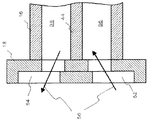
図15を参照すると、上部隔壁部78は、上壁82、下壁84、左右の側壁86、及び中心軸22方向の一端側でそれら4つの壁を連結する端壁88を有し、これらの5つの壁の間に扁平な空間の中空部90が形成されている。また、上壁82は、端壁88の反対側の端面92から端壁88に向かって中心軸22と平行に伸びる複数のスロット94が、中心軸22と直交する方向に所定の間隔をあけて形成されている。スロット94の間隔は対応するフィン40,42の間隔と実質的に同一で、ハウジング14に装着された状態で、フィン40,42の末端がスロット94に嵌り込むように配置されている。   Referring to FIG. 15, the upper partition 78 has an upper wall 82, a lower wall 84, left and right side walls 86, and an end wall 88 that connects these four walls at one end side in the direction of the central axis 22. A hollow portion 90 having a flat space is formed between the five walls. The upper wall 82 has a plurality of slots 94 extending in parallel with the central axis 22 from the end surface 92 opposite to the end wall 88 toward the end wall 88 with a predetermined interval in a direction perpendicular to the central axis 22. Is formed. The distance between the slots 94 is substantially the same as the distance between the corresponding fins 40, 42, and the ends of the fins 40, 42 are arranged so as to fit into the slots 94 when attached to the housing 14.

このように構成された上部隔壁部78は、上述のように、この隔壁部を上下および前後を反転して得られる下部隔壁部80と重ね合わされ、第1の端部開口部26(第1の蓋18に近い開口部)から、上部隔壁部78のスロット開口98および下部隔壁部80のスロット末端96を手前(挿入方向手前)に向けて、上下のフィン40,42の間に挿入することによって装着される。装着された状態で、隔壁部78,80のスロット94には、フィン40,42の末端が嵌っている。   As described above, the upper partition wall 78 configured as described above is overlapped with the lower partition wall 80 obtained by reversing the partition wall up and down and front and rear, and the first end opening 26 (first By inserting the slot opening 98 of the upper partition wall portion 78 and the slot end 96 of the lower partition wall portion 80 toward the front (front side in the insertion direction) between the upper and lower fins 40 and 42 from the opening close to the lid 18). Installed. In the mounted state, the ends of the fins 40 and 42 are fitted into the slots 94 of the partition walls 78 and 80.

スロット94の幅は、後述するようにフィン40,42の幅に応じて決定され、例えばフィン40,42の幅より0.1mm〜1mm程度大きい。そのため、スロット94がフィン40,42の末端で埋められることはない。したがって、スロット94は、中空部90に冷媒56が流れ込むための流路となる。また、上述のように、スロット末端96が冷媒の流れ方向の上流側に、スロット開口98が冷媒の流れ方向の下流側になるように取り付けることによって、中空部90の圧力はフィン40,42近傍を流れる冷媒56の圧力より低くなる。このような圧力勾配により、フィン40、42近傍から、スロット94の中空部90に流入する流れが生じる。   The width of the slot 94 is determined according to the width of the fins 40 and 42 as will be described later, and is, for example, about 0.1 mm to 1 mm larger than the width of the fins 40 and 42. Therefore, the slot 94 is not filled with the end of the fins 40 and 42. Therefore, the slot 94 becomes a flow path for the refrigerant 56 to flow into the hollow portion 90. Further, as described above, by attaching the slot end 96 to the upstream side in the refrigerant flow direction and the slot opening 98 to the downstream side in the refrigerant flow direction, the pressure of the hollow portion 90 is near the fins 40 and 42. It becomes lower than the pressure of the refrigerant | coolant 56 which flows through. Due to such a pressure gradient, a flow that flows into the hollow portion 90 of the slot 94 from the vicinity of the fins 40 and 42 is generated.

フィン40、42の近傍の冷媒は、フィンからの熱を受け、高温となっている。その高温となったフィン40、42の表面近傍の冷媒の一部がスロット94を介して中空部90に流れ込む。結果として、フィン40、42の間を中心軸22と平行な方向に流れる冷媒の温度が低下し(温度境界層の発達が抑制され)、フィンと冷媒の熱交換が促進される。中空部90の冷媒56は、下流側の中空部開口に向かって進行し、この中空部開口を通過すると、下部冷媒通路36を通過した冷媒と合流して連通路50を通過し、上部冷媒通路38に進入する。上部冷媒通路38では、上述した下部冷媒通路36における冷媒56の流れと同様に、フィン40の基端から末端に向かう冷媒56の流れが形成され、その流れによってフィン42の表面に形成される温度境界層の発達が抑制される。また、中空部90の冷媒56は、下流側の中空部開口に向かって進行し、この中空部開口を通過すると、上部冷媒通路38を通過した冷媒と合流して冷媒流出路54から排出される。   The refrigerant in the vicinity of the fins 40 and 42 receives heat from the fins and has a high temperature. Part of the refrigerant in the vicinity of the surfaces of the fins 40 and 42 that has reached a high temperature flows into the hollow portion 90 through the slot 94. As a result, the temperature of the refrigerant flowing between the fins 40 and 42 in the direction parallel to the central axis 22 is reduced (development of the temperature boundary layer is suppressed), and heat exchange between the fins and the refrigerant is promoted. The refrigerant 56 in the hollow portion 90 proceeds toward the hollow portion opening on the downstream side, and when passing through the hollow portion opening, the refrigerant 56 merges with the refrigerant that has passed through the lower refrigerant passage 36 and passes through the communication passage 50, thereby passing through the upper refrigerant passage. Enter 38. In the upper refrigerant passage 38, the flow of the refrigerant 56 from the base end to the end of the fin 40 is formed similarly to the flow of the refrigerant 56 in the lower refrigerant passage 36 described above, and the temperature formed on the surface of the fin 42 by the flow. Development of the boundary layer is suppressed. The refrigerant 56 in the hollow portion 90 travels toward the downstream hollow portion opening, and after passing through the hollow portion opening, merges with the refrigerant that has passed through the upper refrigerant passage 38 and is discharged from the refrigerant outflow passage 54. .

スロット94の幅は、上述のようにフィン40,42の幅より大きいが、大きくしすぎると、中空部90に流れ込む冷媒56が多くなり、スロット94より基端側のフィン40,42の周囲を流れる冷媒56の流速が遅くなる。そのため、フィン40,42の高さ方向の圧力勾配によって温度境界層の発達の抑制にして得られる冷却性能の向上と、冷媒56の流速の低下による冷却性能の低下とを考慮して、結果的にヒートシンクの冷却性能が向上するように、スロット94の幅は決定されるとよい。   The width of the slot 94 is larger than the width of the fins 40 and 42 as described above. However, if the slot 94 is too large, more refrigerant 56 flows into the hollow portion 90, and the periphery of the fins 40 and 42 on the base end side from the slot 94 is increased. The flow rate of the flowing refrigerant 56 becomes slow. Therefore, considering the improvement of the cooling performance obtained by suppressing the development of the temperature boundary layer by the pressure gradient in the height direction of the fins 40 and 42, and the reduction of the cooling performance due to the decrease in the flow velocity of the refrigerant 56, as a result The width of the slot 94 may be determined so that the cooling performance of the heat sink is improved.

また、スロット94の幅は、スロット末端96(上流側)からスロット開口98(下流側)にかけて次第に広くなってもよい。上流側は一般に温度境界層があまり発達していないため、スロット末端96側のスロット94の幅を狭くすることによって、冷媒56の流速を速くすることでヒートシンクの冷却性能は向上する。また、下流側は一般に温度境界層が発達するため、スロット開口98側のスロット94の幅を広くすることによって、温度境界層の発達を抑えることでヒートシンクの冷却性能は向上する。このように、冷媒56の上流から下流にかけて次第にスロット94の幅を広くすることによって、ヒートシンクの冷却性能を向上させることが可能になる。   Further, the width of the slot 94 may gradually increase from the slot end 96 (upstream side) to the slot opening 98 (downstream side). Since the temperature boundary layer is generally not developed on the upstream side, the cooling performance of the heat sink is improved by increasing the flow rate of the refrigerant 56 by narrowing the width of the slot 94 on the slot end 96 side. Further, since the temperature boundary layer generally develops on the downstream side, the cooling performance of the heat sink is improved by suppressing the development of the temperature boundary layer by increasing the width of the slot 94 on the slot opening 98 side. Thus, by gradually increasing the width of the slot 94 from the upstream side to the downstream side of the refrigerant 56, it is possible to improve the cooling performance of the heat sink.

以上のような隔壁によれば、フィン表面において、下流に向かって拡大していく温度境界層の発達を抑制でき、フィンと冷媒の伝熱を促進することによって、ヒートシンクの冷却性能をさらに向上することができる。   According to the partition wall as described above, the development of the temperature boundary layer that expands toward the downstream can be suppressed on the fin surface, and the heat transfer between the fin and the refrigerant is promoted to further improve the cooling performance of the heat sink. be able to.

このように、本実施の形態によれば、フィンに沿ってその基端から末端に向かう冷媒の流れによってフィンの表面に形成される温度境界層の発達が抑制されるため、フィンの放熱能力が最大限に利用され、ヒートシンク10の冷却能力が効率良く発揮される。   As described above, according to the present embodiment, the development of the temperature boundary layer formed on the surface of the fin is suppressed by the flow of the refrigerant from the base end toward the end along the fin. The cooling capacity of the heat sink 10 is efficiently exhibited as much as possible.

また、本実施の形態では、隔壁44は上下のフィン40,42から離間して配置されるため、図17に示すように、隔壁44にはハウジング筒部16の側壁34に対向する位置に被ガイド用突起100又は突条(第1の係合部)を設け、他方、これに対向するハウジング側壁34にはガイド溝102(第2の係合部)を設け、これら突起100とガイド溝102の協働によって、隔壁44をハウジング筒部16に安定して支持することが好ましい。本実施の形態で説明した上部隔壁部78および下部隔壁部80は、樹脂、アルミ、銅などからなり、押し出し成型、射出成型、またはダイキャストなどによって形成される。   Further, in the present embodiment, the partition wall 44 is disposed apart from the upper and lower fins 40 and 42, so that the partition wall 44 is covered at a position facing the side wall 34 of the housing tubular portion 16 as shown in FIG. A guide protrusion 100 or a protrusion (first engagement portion) is provided, and a guide groove 102 (second engagement portion) is provided on the housing side wall 34 opposite to the guide protrusion 100 or protrusion (first engagement portion). It is preferable that the partition wall 44 is stably supported by the housing tube portion 16 by the cooperation. The upper partition wall 78 and the lower partition wall 80 described in the present embodiment are made of resin, aluminum, copper, or the like, and are formed by extrusion molding, injection molding, die casting, or the like.

実施の形態8. Embodiment 8 FIG.

これまでの実施の形態では、隔壁は実質的に平板であり、すなわち中心軸22方向から見た隔壁の断面形状が平らな長方形であったが、隔壁の形状はこれに限られない。例えば、図18は、中心軸22方向から見た隔壁の断面形状が「H」型である隔壁の斜視図である。隔壁104は、平板部106と、その両端の辺に設けられる充填部108とを備える。充填部108は、平板部106の両端の辺に設けられ、左右の側壁34に密着して、下壁30と上壁32に向けて突き出した部位であり、中心軸22方向から見た両端のフィン40,42と左右の側壁34との空間を充填する。   In the embodiments so far, the partition wall is substantially a flat plate, that is, the partition wall has a flat cross-sectional shape viewed from the direction of the central axis 22, but the shape of the partition wall is not limited thereto. For example, FIG. 18 is a perspective view of a partition wall having a “H” sectional shape as viewed from the direction of the central axis 22. The partition wall 104 includes a flat plate portion 106 and filling portions 108 provided on both sides of the flat plate portion 106. The filling portion 108 is provided on both sides of the flat plate portion 106, is in close contact with the left and right side walls 34, and protrudes toward the lower wall 30 and the upper wall 32. The space between the fins 40 and 42 and the left and right side walls 34 is filled.

このような隔壁104は、例えば、中心軸22方向から見た筒部16の断面において、フィン40,42が筒部16の中央部分に設けられ、両端近傍には設けられない場合に用いられる。充填部108を有する隔壁104により、筒部16の両端に位置するフィン40,42と側壁34の内面との空間を充填部108で充填することができ、上部冷媒通路38および下部冷媒通路36を流れる冷媒56の流速を速くすることができる。したがって、ヒートシンクの冷却性能を向上させることが可能になる。発熱体12が、下壁30外面の中央部分、上壁32の外面の中央部分またはそれらのいずれか一方に配置される場合に特に有効である。   Such a partition 104 is used, for example, when the fins 40 and 42 are provided in the central portion of the cylindrical portion 16 in the cross section of the cylindrical portion 16 as viewed from the direction of the central axis 22 and are not provided near both ends. By the partition wall 104 having the filling portion 108, the space between the fins 40, 42 located at both ends of the cylindrical portion 16 and the inner surface of the side wall 34 can be filled with the filling portion 108, and the upper refrigerant passage 38 and the lower refrigerant passage 36 are formed. The flow rate of the flowing refrigerant 56 can be increased. Therefore, it is possible to improve the cooling performance of the heat sink. This is particularly effective when the heating element 12 is disposed at the center portion of the outer surface of the lower wall 30, the center portion of the outer surface of the upper wall 32, or any one of them.

実施の形態9. Embodiment 9 FIG.

蓋18,20は、筒部16の端面形状に対応した大きさを有するとしたが、蓋18は少なくとも筒部16の端面を塞ぐ大きさであればよく、図19に示すように、筒部16の端面形状より大きくてもよい。冷媒56は、冷媒流入路52に接続されるホース(図示せず)から第1の冷媒通路36へ送り込まれ、第2の冷媒流路38から冷媒流出路54に接続されるホース(図示せず)へ排出される。ホースの断面形状が例えば円形である場合、第1の冷媒通路36に十分な圧力で冷媒を送り込み、また、第2の冷媒流路38から円滑に冷媒を排出するには、各冷媒流路36,38の高さよりも大きい直径を有するホースを使用し、それを蓋18に接続する必要がある。そのため、蓋18は、十分に大きい直径を有するホースを接続できるように、筒部16の端面より大きくなる。   The lids 18 and 20 have a size corresponding to the shape of the end face of the cylindrical portion 16, but the lid 18 may be of a size that at least covers the end face of the cylindrical portion 16. As shown in FIG. It may be larger than 16 end face shapes. The refrigerant 56 is fed from a hose (not shown) connected to the refrigerant inflow passage 52 to the first refrigerant passage 36 and is connected to the refrigerant outflow passage 54 from the second refrigerant passage 38 (not shown). ). In the case where the cross-sectional shape of the hose is, for example, a circle, each refrigerant flow path 36 is used to send the refrigerant to the first refrigerant passage 36 with sufficient pressure and to smoothly discharge the refrigerant from the second refrigerant flow path 38. , 38 and use a hose with a diameter larger than the height, and connect it to the lid 18. Therefore, the lid 18 is larger than the end surface of the cylindrical portion 16 so that a hose having a sufficiently large diameter can be connected.

実施の形態10. Embodiment 10 FIG.

本発明は、これまでの実施の形態において説明したヒートシンクが取り付けられた電気機器として実現することもできる。電気機器は、発熱体としてのインバータ、コンバータ、電気回路、半導体デバイスなどを含む機器である。発熱体は、ヒートシンクの周囲に接して取り付けられる。   The present invention can also be realized as an electric device to which the heat sink described in the above embodiments is attached. The electric device is a device including an inverter, a converter, an electric circuit, a semiconductor device and the like as a heating element. The heating element is attached in contact with the periphery of the heat sink.

なお、以上では複数の実施の形態を個別に説明したが、これら複数の実施の形態はそれぞれ、単独でも実施できるし、他の実施の形態と組み合わせて実施できる。当然、複数の実施の形態が組み合わされた実施例は、複数の実施の形態の個々の効果を発揮し得るものである。   In addition, although several embodiment was demonstrated separately above, these several embodiment can each be implemented independently, and can be implemented in combination with other embodiment. Naturally, an example in which a plurality of embodiments are combined can exhibit the individual effects of the plurality of embodiments.

実施の形態1のヒートシンクの外観を示す斜視図である。1 is a perspective view illustrating an appearance of a heat sink according to Embodiment 1. FIG. 実施の形態1のヒートシンクの全体を示す側方断面図である。1 is a side sectional view showing an entire heat sink according to a first embodiment. 実施の形態1の隔壁が取り付けられた中空角管の斜視図である。It is a perspective view of the hollow square tube to which the partition of Embodiment 1 was attached. 実施の形態3の第1の蓋の外観を示す斜視図である。FIG. 10 is a perspective view showing an appearance of a first lid of a third embodiment. 実施の形態4の第1の蓋の斜視図である。FIG. 10 is a perspective view of a first lid according to the fourth embodiment. 実施の形態4の隔壁の斜視図である。It is a perspective view of the partition of Embodiment 4. 実施の形態4の変形例の第1の蓋の側方断面図である。FIG. 10 is a side cross-sectional view of a first lid of a modification of the fourth embodiment. 実施の形態5の隔壁の第1の例の斜視図である。It is a perspective view of the 1st example of the partition of Embodiment 5. FIG. 実施の形態5の隔壁の第2の例の斜視図である。It is a perspective view of the 2nd example of the partition of Embodiment 5. 実施の形態5の隔壁の第3の例の側面図である。It is a side view of the 3rd example of the partition of Embodiment 5. 実施の形態6の隔壁の第1の例を示す斜視図である。It is a perspective view which shows the 1st example of the partition of Embodiment 6. FIG. 実施の形態6の第1の例の隔壁を筒部に取り付けた状態を示す正面図である。It is a front view which shows the state which attached the partition of the 1st example of Embodiment 6 to the cylinder part. 実施の形態6の隔壁の第2の例を示す斜視図である。It is a perspective view which shows the 2nd example of the partition of Embodiment 6. FIG. 実施の形態6の隔壁の第3の例を示す斜視図である。FIG. 24 is a perspective view showing a third example of the partition wall according to the sixth embodiment. 実施の形態7の隔壁の上部隔壁部を示す斜視図である。It is a perspective view which shows the upper partition part of the partition of Embodiment 7. FIG. 実施の形態7の隔壁の下部隔壁部を示す斜視図である。It is a perspective view which shows the lower partition part of the partition of Embodiment 7. FIG. 実施の形態7の隔壁を筒部に取り付けた状態を示す正面図である。It is a front view which shows the state which attached the partition of Embodiment 7 to the cylinder part. 実施の形態8の隔壁の斜視図である。FIG. 10 is a perspective view of a partition wall according to an eighth embodiment. 実施の形態9の蓋の側方断面図である。10 is a side sectional view of a lid according to a ninth embodiment. FIG.

符号の説明Explanation of symbols

10:ヒートシンク
12:発熱体
14:ハウジング
16:筒部
18:第1の蓋
20:第2の蓋
22:中心軸
24:内空部
26:第1の端部開口部
28:第2の端部開口部
30:下壁
32:上壁
34:側壁
36:第1の冷媒通路
38:第2の冷媒通路
40:第1のフィン
42:第2のフィン
44:隔壁
46:隔壁の一端
48:隔壁の他端
50:連通路
52:冷媒流入路(第1の冷媒通路)
54:冷媒流出路(第2の冷媒通路)
56:冷媒
58:分流ヘッダ
59:合流ヘッダ
60:隔壁部
62:突出隔壁部
64,67:溝
66:突条
68:撹拌部
70:フィン挿入スロット
72:乱流促進ピン
74:傾斜面
78:上部隔壁部
80:下部隔壁部
82:上壁
84:下壁
86:側壁
88:端壁
90:中空部
92:端壁
94:スロット
96:スロット開口
98:スロット末端
100:突起
102:ガイド溝
104:隔壁
106:平板部
108:充填部
10: heat sink 12: heating element 14: housing 16: tube 18: first lid 20: second lid 22: central axis 24: inner space 26: first end opening 28: second end Part opening 30: lower wall 32: upper wall 34: side wall 36: first refrigerant passage 38: second refrigerant passage 40: first fin 42: second fin 44: partition 46: one end 48 of the partition 48: The other end 50 of the partition wall: the communication path 52: the refrigerant inflow path (first refrigerant path)
54: Refrigerant outflow path (second refrigerant path)
56: Refrigerant 58: Shunt header 59: Merge header 60: Partition 62: Projecting partition 64, 67: Groove 66: Projection 68: Stirrer 70: Fin insertion slot 72: Turbulence promotion pin 74: Inclined surface 78: Upper partition wall portion 80: Lower partition wall portion 82: Upper wall 84: Lower wall 86: Side wall 88: End wall 90: Hollow portion 92: End wall 94: Slot 96: Slot opening 98: Slot end 100: Projection 102: Guide groove 104 : Partition wall 106: flat plate part 108: filling part

Claims (12)

発熱体に取り付けられ、前記発熱体を冷却するヒートシンクであって、
第1の冷媒流路と前記第1の冷媒流路に隣接する第2の冷媒流路を形成するハウジングと、
前記第1と第2の冷媒流路の間に配置され、前記第1と第2の冷媒流路を隔離する隔壁と、
前記ハウジングに一体的に形成された、前記第1の冷媒流路に突出した複数の第1のフィンと前記第2の冷媒流路に突出した複数の第2のフィンとを備えたことを特徴とするヒートシンク。
A heat sink attached to the heating element for cooling the heating element,
A housing forming a first refrigerant channel and a second refrigerant channel adjacent to the first refrigerant channel;
A partition wall disposed between the first and second refrigerant flow paths and separating the first and second refrigerant flow paths;
A plurality of first fins protruding into the first refrigerant flow path and a plurality of second fins protruding into the second refrigerant flow path are formed integrally with the housing. And heat sink.
さらに、前記第1の冷媒流路の下流側であって前記第2の冷媒流路の上流側に設けられ、前記第1と第2の冷媒流路を連通する連通路を備えることを特徴とする請求項1に記載のヒートシンク。   Furthermore, it is provided on the downstream side of the first refrigerant flow path and the upstream side of the second refrigerant flow path, and includes a communication path that communicates the first and second refrigerant flow paths. The heat sink according to claim 1. 前記ハウジングは、前記第1の冷媒流路の上流側であって前記第2の冷媒流路の下流側に位置する第1の端部開口部と、前記第1の冷媒流路の下流側であって前記第2の冷媒流路の上流側に位置する第2の端部開口部を有し、
前記ハウジングは、前記第1と第2の端部開口部をそれぞれ塞ぐ第1と第2の蓋を有することを特徴とする請求項1または2に記載のヒートシンク。
The housing includes a first end opening located upstream of the first refrigerant flow path and downstream of the second refrigerant flow path, and a downstream side of the first refrigerant flow path. And having a second end opening located upstream of the second refrigerant flow path,
The heat sink according to claim 1 or 2, wherein the housing has first and second lids for closing the first and second end openings, respectively.
前記第1の流路の下流側であって前記第2の流路の上流側に位置する前記隔壁の端部が前記第2の端部開口部から離間して配置されて前記連通路が形成されていることを特徴とする請求項3に記載のヒートシンク。   An end of the partition located downstream of the first flow path and upstream of the second flow path is disposed away from the second end opening to form the communication path. The heat sink according to claim 3, wherein the heat sink is provided. 前記隔壁は前記第1と第2の端部開口部の間で連続的に伸びており、前記連通路は前記隔壁に形成されていることを特徴とする請求項3に記載のヒートシンク。   The heat sink according to claim 3, wherein the partition wall continuously extends between the first and second end opening portions, and the communication path is formed in the partition wall. 前記第1の蓋は前記第1の冷媒流路に連通する第1の通路と前記第2の冷媒流路に連通する第2の通路を有することを特徴とする請求項3から5いずれか1項に記載のヒートシンク。   6. The first lid according to claim 3, further comprising a first passage communicating with the first refrigerant flow path and a second passage communicating with the second refrigerant flow path. Heat sink according to item. 前記第1の通路は、前記第1の冷媒流路に直接連通して、前記第1の冷媒流路に冷媒を分散させる分流ヘッダを含み、前記第2の通路は、前記第2の冷媒流路に直接連通して、前記第2の冷媒流路から冷媒を回収する合流ヘッダを含むことを特徴とする請求項6に記載のヒートシンク。   The first passage is in direct communication with the first refrigerant flow path, and includes a diversion header that disperses the refrigerant in the first refrigerant flow path, and the second passage includes the second refrigerant flow. The heat sink according to claim 6, further comprising a merge header that directly communicates with a path and collects the refrigerant from the second refrigerant flow path. 前記第1の流路の下流側であって前記第2の流路の上流側に位置する前記隔壁の端部に、前記第1または第2の流路に突出して形成された撹拌部が形成されていることを特徴とする請求項1から7いずれか1項に記載のヒートシンク。   An agitating portion that protrudes from the first or second flow path is formed at the end of the partition located downstream of the first flow path and upstream of the second flow path. The heat sink according to any one of claims 1 to 7, wherein the heat sink is formed. 前記隔壁は、前記第1および第2のフィンの少なくとも一方の間に乱流促進ピンを有することを特徴とする請求項1から8いずれか1項に記載のヒートシンク。   The heat sink according to any one of claims 1 to 8, wherein the partition wall includes a turbulence promoting pin between at least one of the first and second fins. 前記隔壁は、
周囲が壁で囲われる中空部と、前記第1のフィンに対向する位置であって当該壁に設けられるスロットと、前記第1の冷媒流路の下流側に開口を有する第1隔壁部と、
周囲が壁で囲われる中空部と、前記第2のフィンに対向する位置であって当該壁に設けられるスロットと、前記第2の冷媒流路の下流側に開口を有する第2隔壁部とから構成されることを特徴とする請求項1から9いずれか1項に記載のヒートシンク。
The partition is
A hollow portion surrounded by a wall, a slot provided in the wall at a position facing the first fin, a first partition wall portion having an opening on the downstream side of the first refrigerant flow path,
A hollow portion surrounded by a wall; a slot provided in the wall at a position facing the second fin; and a second partition wall portion having an opening on the downstream side of the second refrigerant flow path. The heat sink according to claim 1, wherein the heat sink is configured.
前記隔壁は、前記ハウジングでの取り付け位置に案内する第1の係合部を有し、前記ハウジングは、前記第1の係合部と係合し、前記隔壁を案内する第2の係合部を有することを特徴とする請求項1から10いずれか1項に記載のヒートシンク。   The partition has a first engagement portion that guides to a mounting position on the housing, and the housing engages with the first engagement portion and guides the partition. The heat sink according to claim 1, comprising: 発熱体を含む電気機器であって、
前記発熱体に取り付けられるヒートシンクを備え、
前記ヒートシンクは、
第1の冷媒流路と前記第1の冷媒流路に隣接する第2の冷媒流路を形成するハウジングと、
前記第1と第2の冷媒流路の間に配置され、前記第1と第2の冷媒流路を隔離する隔壁と、
前記ハウジングに一体的に形成された、前記第1の冷媒流路に突出した複数の第1のフィンと前記第2の冷媒流路に突出した複数の第2のフィンとを備えたことを特徴とする電気機器。
An electrical device including a heating element,
Comprising a heat sink attached to the heating element;
The heat sink is
A housing forming a first refrigerant channel and a second refrigerant channel adjacent to the first refrigerant channel;
A partition wall disposed between the first and second refrigerant flow paths and separating the first and second refrigerant flow paths;
A plurality of first fins protruding into the first refrigerant flow path and a plurality of second fins protruding into the second refrigerant flow path are formed integrally with the housing. And electrical equipment.
JP2008012650A 2008-01-23 2008-01-23 Heat sink and electrical equipment Active JP5084527B2 (en)

Priority Applications (1)

Application Number Priority Date Filing Date Title
JP2008012650A JP5084527B2 (en) 2008-01-23 2008-01-23 Heat sink and electrical equipment

Applications Claiming Priority (1)

Application Number Priority Date Filing Date Title
JP2008012650A JP5084527B2 (en) 2008-01-23 2008-01-23 Heat sink and electrical equipment

Publications (2)

Publication Number Publication Date
JP2009176871A true JP2009176871A (en) 2009-08-06
JP5084527B2 JP5084527B2 (en) 2012-11-28

Family

ID=41031677

Family Applications (1)

Application Number Title Priority Date Filing Date
JP2008012650A Active JP5084527B2 (en) 2008-01-23 2008-01-23 Heat sink and electrical equipment

Country Status (1)

Country Link
JP (1) JP5084527B2 (en)

Cited By (5)

* Cited by examiner, † Cited by third party
Publication number Priority date Publication date Assignee Title
WO2011083578A1 (en) * 2010-01-08 2011-07-14 トヨタ自動車株式会社 Semiconductor module
JP2012060040A (en) * 2010-09-13 2012-03-22 Showa Denko Kk Cooler
CN102751250A (en) * 2011-04-19 2012-10-24 株式会社丰田自动织机 Cooling device
JP2014079117A (en) * 2012-10-11 2014-05-01 Mitsubishi Electric Corp On-vehicle power conversion apparatus
JP2014220452A (en) * 2013-05-10 2014-11-20 三菱電機株式会社 Cooler for electronic component

Citations (5)

* Cited by examiner, † Cited by third party
Publication number Priority date Publication date Assignee Title
JPS61174750U (en) * 1985-04-22 1986-10-30
JPH0624279A (en) * 1992-05-12 1994-02-01 Nippondenso Co Ltd Cooling device for electric automobile
WO2000011922A1 (en) * 1998-08-18 2000-03-02 Hamamatsu Photonics K.K. Heat sink, and semiconductor laser and semiconductor laser stacker using the same
JP2001035981A (en) * 1999-07-16 2001-02-09 Toshiba Corp Cooler for semiconductor element and power-converting device using it
JP2005101461A (en) * 2003-09-26 2005-04-14 Denso Corp Counter oscillating flow type heat transport device

Patent Citations (5)

* Cited by examiner, † Cited by third party
Publication number Priority date Publication date Assignee Title
JPS61174750U (en) * 1985-04-22 1986-10-30
JPH0624279A (en) * 1992-05-12 1994-02-01 Nippondenso Co Ltd Cooling device for electric automobile
WO2000011922A1 (en) * 1998-08-18 2000-03-02 Hamamatsu Photonics K.K. Heat sink, and semiconductor laser and semiconductor laser stacker using the same
JP2001035981A (en) * 1999-07-16 2001-02-09 Toshiba Corp Cooler for semiconductor element and power-converting device using it
JP2005101461A (en) * 2003-09-26 2005-04-14 Denso Corp Counter oscillating flow type heat transport device

Cited By (10)

* Cited by examiner, † Cited by third party
Publication number Priority date Publication date Assignee Title
WO2011083578A1 (en) * 2010-01-08 2011-07-14 トヨタ自動車株式会社 Semiconductor module
CN102612747A (en) * 2010-01-08 2012-07-25 丰田自动车株式会社 Semiconductor module
JP5423811B2 (en) * 2010-01-08 2014-02-19 トヨタ自動車株式会社 Semiconductor module
US8755185B2 (en) 2010-01-08 2014-06-17 Toyota Jidosha Kabushiki Kaisha Semiconductor module
JP2012060040A (en) * 2010-09-13 2012-03-22 Showa Denko Kk Cooler
CN102751250A (en) * 2011-04-19 2012-10-24 株式会社丰田自动织机 Cooling device
US8899307B2 (en) 2011-04-19 2014-12-02 Kabushiki Kaisha Toyota Jidoshokki Cooling device
DE102012206360B4 (en) * 2011-04-19 2015-09-10 Kabushiki Kaisha Toyota Jidoshokki cooler
JP2014079117A (en) * 2012-10-11 2014-05-01 Mitsubishi Electric Corp On-vehicle power conversion apparatus
JP2014220452A (en) * 2013-05-10 2014-11-20 三菱電機株式会社 Cooler for electronic component

Also Published As

Publication number Publication date
JP5084527B2 (en) 2012-11-28

Similar Documents

Publication Publication Date Title
JP5983565B2 (en) Cooler
JP5343007B2 (en) Liquid cooling system
JP5084527B2 (en) Heat sink and electrical equipment
JP2010056130A (en) Liquid-cooled-type cooling device
JP2010056131A (en) Liquid-cooled-type cooling device
JP6026772B2 (en) heatsink
JP6109265B2 (en) Electric equipment with refrigerant flow path
US20130292091A1 (en) Cooler
JP2009231677A (en) Liquid-cooled type cooling device
JP4913333B2 (en) Heat sink and uniform cooling method
JP2009206271A (en) Heat generating body cooling device
JP2009099740A (en) Cooling device for housing
JP5129942B2 (en) Semiconductor device
JP2008288330A (en) Semiconductor device
JP2016207928A (en) Heat sink for cooling multiple heating components
JP6623120B2 (en) Liquid cooling system
JP2019114682A (en) Liquid-cooled cooler
JP2011134978A (en) Fluid cooling type heat sink
JP5701335B2 (en) Power converter
JP2000299585A (en) Cooling device
CN216528867U (en) Heat radiating fin and heat radiator with same
CN114845527A (en) Phase change cooling type machine box and system thereof
JP2010210202A (en) Heat exchange body
JP2005011928A (en) Liquid-cooling circulation system
JP2013128051A (en) Cooling device for inverter circuit

Legal Events

Date Code Title Description
A621 Written request for application examination

Free format text: JAPANESE INTERMEDIATE CODE: A621

Effective date: 20100119

A977 Report on retrieval

Free format text: JAPANESE INTERMEDIATE CODE: A971007

Effective date: 20111028

A131 Notification of reasons for refusal

Free format text: JAPANESE INTERMEDIATE CODE: A131

Effective date: 20111108

A521 Request for written amendment filed

Free format text: JAPANESE INTERMEDIATE CODE: A523

Effective date: 20111228

TRDD Decision of grant or rejection written
A01 Written decision to grant a patent or to grant a registration (utility model)

Free format text: JAPANESE INTERMEDIATE CODE: A01

Effective date: 20120807

A01 Written decision to grant a patent or to grant a registration (utility model)

Free format text: JAPANESE INTERMEDIATE CODE: A01

A61 First payment of annual fees (during grant procedure)

Free format text: JAPANESE INTERMEDIATE CODE: A61

Effective date: 20120904

R150 Certificate of patent or registration of utility model

Ref document number: 5084527

Country of ref document: JP

Free format text: JAPANESE INTERMEDIATE CODE: R150

FPAY Renewal fee payment (event date is renewal date of database)

Free format text: PAYMENT UNTIL: 20150914

Year of fee payment: 3

R250 Receipt of annual fees

Free format text: JAPANESE INTERMEDIATE CODE: R250

R250 Receipt of annual fees

Free format text: JAPANESE INTERMEDIATE CODE: R250

R250 Receipt of annual fees

Free format text: JAPANESE INTERMEDIATE CODE: R250

R250 Receipt of annual fees

Free format text: JAPANESE INTERMEDIATE CODE: R250

R250 Receipt of annual fees

Free format text: JAPANESE INTERMEDIATE CODE: R250

R250 Receipt of annual fees

Free format text: JAPANESE INTERMEDIATE CODE: R250

R250 Receipt of annual fees

Free format text: JAPANESE INTERMEDIATE CODE: R250

R250 Receipt of annual fees

Free format text: JAPANESE INTERMEDIATE CODE: R250

R250 Receipt of annual fees

Free format text: JAPANESE INTERMEDIATE CODE: R250