JP2009176181A - Rotating disk of coin hopper - Google Patents
Rotating disk of coin hopper Download PDFInfo
- Publication number
- JP2009176181A JP2009176181A JP2008015860A JP2008015860A JP2009176181A JP 2009176181 A JP2009176181 A JP 2009176181A JP 2008015860 A JP2008015860 A JP 2008015860A JP 2008015860 A JP2008015860 A JP 2008015860A JP 2009176181 A JP2009176181 A JP 2009176181A
- Authority
- JP
- Japan
- Prior art keywords
- rotating disk
- coin
- hopper
- hole
- coins
- Prior art date
- Legal status (The legal status is an assumption and is not a legal conclusion. Google has not performed a legal analysis and makes no representation as to the accuracy of the status listed.)
- Pending
Links
Images


Abstract
Description
本発明は、コイン等をホッパヘッドから1枚ずつ送り出すための回転ディスクに関するものである。特に回転ディスクがそのコインが落下する通孔に確実に取り込まれ、コインの払出率が向上するように図った回転ディスクの改良に関する。
なお、本明細書で使用する「コイン」とは、通貨であるコイン、ゲーム機のメダルやトークン等の代用貨幣、およびそれらと類似のものを包含する。
The present invention relates to a rotating disk for feeding coins one by one from a hopper head. In particular, the present invention relates to an improvement of a rotating disk in which the rotating disk is surely taken into a through-hole in which the coin falls and the coin payout rate is improved.
Note that “coin” used in this specification includes coins as currency, substitute money such as medals and tokens of game machines, and the like.
この種の払出装置として、特開2001−14507号公報、特開2000−306132号公報に記載するものが知られている。この種装置は、ホッパヘッドの底部に配した回転ディスクの回転により、ホッパヘッド内にバラ積み状態で収納したコインが攪拌回転されると共に、回転ディスクの周辺部に形成されている複数個の通孔に取り込まれる。取り込まれたコインは、回転ディスクの下に配置したガイド板上を、回転ディスクにおける前記通孔の下面の近傍に設けてある送り爪によって強制的に移動され、所定の個所で出口から送り出されるように構成されている。 As this type of dispensing device, those described in Japanese Patent Application Laid-Open Nos. 2001-14507 and 2000-306132 are known. In this type of apparatus, rotation of a rotating disk arranged at the bottom of the hopper head causes the coins stored in a stacked state in the hopper head to be agitated and rotated, and to a plurality of through holes formed in the peripheral part of the rotating disk. It is captured. The taken-in coins are forcibly moved on a guide plate arranged under the rotating disk by a feeding claw provided in the vicinity of the lower surface of the through hole in the rotating disk, and are sent out from an outlet at a predetermined location. It is configured.
上記公報に示す従来装置において、周方向に複数のコイン受け入れ用の通孔を形成した回転ディスクは、その通孔の最も外側の部分、すなわちディスクの中心と反対側のディスクの最外周縁部分には、幅が僅ではあるが、弧状の骨部(リブ)が存在する。
その骨部は、回転ディスクがホッパヘッド内に組み込まれたときにも、ホッパの筒状の周壁の内側で、周壁と回転ディスクの通孔との間で存在するようになる。
すると、回転ディスクの回転により攪拌されたコインの或るものは、通孔までに存在するこの僅かであるが前述のその骨部(縁部)に立ったまま、ホッパの周壁内面にもたれかかったままとなって、容易に通孔に入り込まないことが起きる。
In the conventional apparatus shown in the above publication, the rotating disk having a plurality of coin receiving holes in the circumferential direction is arranged at the outermost part of the through hole, that is, the outermost peripheral part of the disk opposite to the center of the disk. Has an arcuate bone (rib), although its width is small.
Even when the rotating disk is incorporated in the hopper head, the bone portion exists between the peripheral wall and the through hole of the rotating disk inside the cylindrical peripheral wall of the hopper.
Then, some of the coins agitated by the rotation of the rotating disk leaned against the inner surface of the peripheral wall of the hopper while standing on the bone part (edge part) of the small part existing up to the through hole. As a result, it does not easily enter the through hole.
こうなるとコインの通孔への落ち込み率が悪くなるので、コインの払い出し率が低下し、払い出し性能が劣ると言う欠点があった。
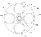
図7は、その問題の現象を概略的に示した図である。図8は、上記問題を抱えていた改良前の回転ディスクの平面図である。図7で、コインホッパ(1)の円筒状に形成されたホッパヘッド(18)内に回転ディスク(4d)が回転自在に配置されている。回転ディスク(4d)はその直下にあるガイド板(5d)に対して、払い出すコインの厚みに応じて調整した間隔(t)だけ離して設置されている。
ホッパ(1)内で回転ディスク(4d)により攪拌回転されるコイン(C)のうち、あるコイン(C)は、図7より理解されるように、コイン(C)が回転ディスク(4d)の外周縁部において、通孔(8)の外側縁部に残る前述した骨部(15r)に乗り、ホッパヘッド(18)の内壁面(18s)にもたれながら立つ状態になる。このためこのような立ったままにあるコイン(C)は通孔(8)に入り込まなくなり、その現象が頻繁に起こり得るので、コインの取り込み率が低下し、払い出し性能が落ちる。
なお、回転ディスク(4)における上述の骨部(縁部)は、図7および図8の回転ディスクを示す図において、図番(15r)で示した部分である。
In this case, the rate of coin drop into the through hole is deteriorated, so that the coin payout rate is lowered and the payout performance is inferior.
FIG. 7 is a diagram schematically showing the phenomenon of the problem. FIG. 8 is a plan view of the rotating disk before improvement which has the above problem. In FIG. 7, the rotating disk (4d) is rotatably arranged in a hopper head (18) formed in a cylindrical shape of the coin hopper (1). The rotating disk (4d) is set apart from the guide plate (5d) immediately below it by an interval (t) adjusted according to the thickness of the coin to be paid out.
Among the coins (C) that are stirred and rotated by the rotating disk (4d) in the hopper (1), as shown in FIG. 7, the coin (C) is the rotating disk (4d). At the outer peripheral edge, it rides on the bone part (15r) remaining on the outer edge of the through hole (8) and stands while leaning against the inner wall surface (18s) of the hopper head (18). For this reason, the standing coin (C) does not enter the through hole (8), and this phenomenon can occur frequently, so that the coin take-in rate is reduced and the payout performance is lowered.
In addition, the above-mentioned bone part (edge part) in the rotating disk (4) is a part indicated by a drawing number (15r) in the drawings showing the rotating disk in FIGS.
ところで、この問題となる現象の解決のために、ホッパヘッド内において回転ディスクの上述の骨部(15r)並びに骨部(15r)をも含めた回転ディスクの外周縁部(15m)がホッパヘッドの内周面側に残らないように、すなわち表出しないようにする構造のものもある。
図9はその例の構成である。この場合、内径がホッパヘッド(18)と合致する筒状のフード(19)とリング状のスペース(21)とを別途新たな構成部品として追加する。そして、ガイド板(5d)の上に前記スペーサ(21)を配置し、スペーサ(21)とホッパヘッド(18)との間に前記フード(19)を配設する。
フード(19)にはその下端部の内周面部に、前記回転ディスク(4d)の骨部(15r)並びに外周縁部(15m)を収納し隠すことが出来るように、前記ホッパヘッド(18)の内径より若干径大な大きさの凹み部(22)が円状に形設されている。
こうすることで、ホッパヘッド(18)の内周面(18s)とフード(19)の内周面(19s)と通孔(8)の内周面(8s)とが上下方向で一致し面一になり、フード(19)の内周面(19s)の下端には、回転ディスクの通孔(8)の骨部(15r)が存在せず、その骨部(15r)は前記フードの凹み部(22)内に入って隠れてしまい、ホッパの内周縁に表出しなくなる。
よって、同図に示すように、コイン(C)が通孔(8)の骨部(15r)に乗ることができなくなり、コイン(C)は通孔(8)に入るようになる。
By the way, in order to solve this problem, the outer peripheral edge (15m) of the rotating disk including the bone part (15r) and the bone part (15r) of the rotating disk in the hopper head is the inner periphery of the hopper head. There is also a structure that does not remain on the surface side, that is, does not expose.
FIG. 9 shows the configuration of the example. In this case, a cylindrical hood (19) whose inner diameter matches the hopper head (18) and a ring-shaped space (21) are separately added as new components. Then, the spacer (21) is disposed on the guide plate (5d), and the hood (19) is disposed between the spacer (21) and the hopper head (18).
In the hood (19), the hopper head (18) can be concealed so that the bone portion (15r) and the outer peripheral edge portion (15m) of the rotating disk (4d) can be accommodated and concealed on the inner peripheral surface portion of the lower end portion thereof. A recess (22) having a diameter slightly larger than the inner diameter is formed in a circular shape.
By doing so, the inner peripheral surface (18s) of the hopper head (18), the inner peripheral surface (19s) of the hood (19), and the inner peripheral surface (8s) of the through hole (8) coincide with each other in the vertical direction. The bone portion (15r) of the through hole (8) of the rotating disk does not exist at the lower end of the inner peripheral surface (19s) of the hood (19), and the bone portion (15r) is a recessed portion of the hood. (22) It goes inside and hides, and it doesn't appear on the inner edge of the hopper.
Therefore, as shown in the figure, the coin (C) cannot get on the bone part (15r) of the through hole (8), and the coin (C) enters the through hole (8).
しかし、このタイプの構造のものは、筒状のフード(19)やリング状のスペーサ(21)などの部材を必要とする等、構成部品も多く構造的にも複雑となりコスト高ともなる。
また、払い出すコインの種類が変更となった場合に、回転ディスク(4d)とガイド板(5d)との間の間隔調整には、それに適合する高さ寸法の別のスペーサ(21)に交換する作業や、フード(19)の取り外しなどの作業が必要となり、再組み立てする等、変更作業が煩雑となって能率的でないという問題等がある。
However, this type of structure requires many components such as a cylindrical hood (19) and a ring-shaped spacer (21), and is structurally complicated and expensive.
Also, when the type of coins to be paid out is changed, the distance between the rotating disk (4d) and the guide plate (5d) can be adjusted with another spacer (21) with a suitable height. Work and removal of the hood (19) are required, and there is a problem that the change work such as reassembly is complicated and inefficient.
これに対し、前述した図7に示す構造のコインホッパのものは、ホッパヘッド(18)内に回転ディスク(4d)を内挿した構造であるから、回転ディスク(4d)をホッパヘッド(18)の面一な内面の内側で難なく上下方向に移動することが可能である。
よってこのタイプのコインホッパの方が、簡素な構造であってコスト的にも安価であると言う利点に加えて、コインの種類の変更に応じて回転ディスクをガイド板に対して間隔調整をして設置する(コインの厚みに応じた回転ディスクの高さ調整)ことが容易なので、払出しコインの変更に即応できて好適である。
しかしその反面、上述したような骨部(15r)が回転ディスク(4d)においてその通孔(8)の外周辺部側で残るので、コイン(C)が前記骨部(15r)の上に立ち残ったままとなり、コインの払い出し率が悪くなると言う問題があった。
本発明はこの点の問題に鑑みなされたもので、この種の払い出しコインの変更に適したタイプのコインホッパにおいて、上述したコインの回転ディスクの外周縁部上での立ち上がりが無くなり、コインが通孔に取り込み易くなり、払い出し性能が高まるように改良したコインホッパの回転ディスクを提供するものである。
On the other hand, since the coin hopper having the structure shown in FIG. 7 has a structure in which the rotating disk (4d) is inserted into the hopper head (18), the rotating disk (4d) is flush with the hopper head (18). It is possible to move up and down without difficulty inside the inner surface.
Therefore, in addition to the advantage that this type of coin hopper has a simple structure and is inexpensive, the rotating disk is adjusted with respect to the guide plate according to the change of the coin type. Since it is easy to install (adjusting the height of the rotating disk in accordance with the thickness of the coin), it is possible to respond immediately to the change of the payout coin.
However, on the other hand, the bone (15r) as described above remains on the outer peripheral side of the through hole (8) in the rotating disk (4d), so that the coin (C) stands on the bone (15r). There was a problem that the coins payout rate deteriorated.
The present invention has been made in view of this problem. In a coin hopper of a type suitable for changing this type of payout coin, the above-described coin does not rise on the outer peripheral edge of the rotating disk, and the coin passes through the hole. It is an object of the present invention to provide a coin hopper rotating disk which is improved so that it can be easily taken in and the payout performance is improved.
この目的を達成するため本発明のコインホッパの回転ディスクは、ホッパ本体の上部に配置した基台上に設置された、コインがバラ積み状態で保留されるホッパヘッドと、該ホッパヘッドの内底部に回転駆動自在に配設され、コインが落下する複数の通孔が周辺部に円周状に配置形成されている回転ディスクと、前記通孔に受け入れたコインを前記回転ディスクの回転時にその押進突起にてコイン出口へと滑動案内するように前記回転ディスクの下方に配置されたガイド板とを備えたコインホッパにおいて、前記回転ディスクには、コインを前記通孔へと誘導落下させる斜面部を回転ディスクの外周縁部に立設形成したものである。 In order to achieve this object, the coin hopper rotating disk of the present invention has a hopper head installed on a base placed on the top of the hopper body, in which coins are held in a stacked state, and driven to rotate at the inner bottom of the hopper head. A rotating disk that is freely arranged and has a plurality of through holes through which coins fall circumferentially arranged at the periphery thereof, and a coin received in the through hole is used as a pushing projection when the rotating disk rotates. In the coin hopper provided with a guide plate disposed under the rotating disk so as to slide and guide to the coin outlet, the rotating disk has a slope portion for guiding and dropping the coin into the through hole of the rotating disk. It is formed upright on the outer peripheral edge.
請求項2の発明は、請求項1のコインホッパの回転ディスクにおいて、前記傾斜部は、前記通孔の最も外側の縁部に連なって前記回転ディスクをリング状に取り囲むように全周に突設された内側が下向き傾斜の傾斜面に形成された突出縁であることを特徴とするものである。 According to a second aspect of the present invention, in the rotating disk of the coin hopper according to the first aspect, the inclined portion is connected to the outermost edge of the through hole so as to project around the rotating disk in a ring shape. The inner side is a protruding edge formed on a downwardly inclined surface.
この構成によれば、回転ディスクの回転によってホッパヘッド内のコインが攪拌され、通孔に落下する。
落下したコインは、回転ディスクの押進突起によって押進される。
従来の回転ディスクであれば、コインがホッパヘッドの壁面にもたれかかり、通孔の縁(骨部)で立つことがあったのが、本発明であれば、その通孔の縁には通孔に向かう下向きの斜面部があり、コインが乗るような骨部を無くしているので、コインが通孔の縁で起立することはできず、下向きの斜面部によって通孔へと誘導落下されるようになる。
よって、コインの回転ディスクの通孔への落ち込み率が良くなり、効率良く回転ディスクはコインを捕捉し払い出すことができるようになり、ホッパ装置によるコイン処理が向上する。
回転ディスクの通孔の外周辺部当りに傾斜部を設けた構造であっても、回転ディスクはホッパヘッドに内挿した構造のタイプのホッパヘッドなので、回転ディスクをホッパヘッド内で上下移動するのには何ら支障無く、よって払い出しコインの種類(厚み)に応じた回転ディスクの設置高さの変更調整も簡単に対処できるようになるので、コイン捕捉率は良好に確保したまま、払い出しコインの種類(厚み)に応じた回転ディスクの設置高さの変更調整も簡単に対処でき、その実用性は高いものである。
According to this configuration, the coin in the hopper head is agitated by the rotation of the rotating disk and falls into the through hole.
The dropped coin is pushed by the pushing protrusion of the rotating disk.
In the case of the conventional rotating disk, the coin leans against the wall surface of the hopper head and sometimes stands at the edge (bone part) of the through hole. In the present invention, the edge of the through hole faces the through hole. Since there is a downward slope and there is no bone part where coins can ride, the coin cannot stand up at the edge of the through hole, and it will be guided and dropped to the through hole by the downward slope .
Therefore, the rate of falling of coins into the through-holes of the rotating disk is improved, the rotating disk can efficiently capture and pay out coins, and the coin processing by the hopper device is improved.
Even if the rotating disk has a structure with an inclined portion around the outer periphery of the through hole of the rotating disk, the rotating disk is a type of hopper head that is inserted into the hopper head, so there is nothing to move the rotating disk up and down in the hopper head. There is no hindrance, so it is possible to easily adjust the setting height of the rotating disk according to the type (thickness) of the coins to be paid out, so the type (thickness) of the coins to be paid out while maintaining a good coin capture rate. It can easily cope with the change and adjustment of the installation height of the rotating disk according to the above, and its practicality is high.
また、回転ディスクの外周全部(全周)に突出縁をリング状に設け、その突出縁の内側面を傾斜面として傾斜部を設けるようにすれば、コインが回転ディスクの周辺のどこにあっても、回転ディスクの中心へと向かって滑り落とされるようになるので、コイン全体の通孔への捕捉率が更に良くなるので、回転ディスクのコイン払い出し性能が一層向上する。
傾斜部の形成は、回転ディスクの成型時に同時成形で得ることが可能なので、廉価に提供可能である。
In addition, if a protruding edge is provided in a ring shape on the entire outer periphery (the entire periphery) of the rotating disk, and an inclined portion is provided with the inner surface of the protruding edge as an inclined surface, the coin can be located anywhere around the rotating disk. Since it is slid down toward the center of the rotating disk, the capture rate of the entire coin in the through hole is further improved, and the coin payout performance of the rotating disk is further improved.
The formation of the inclined portion can be obtained at the same time when the rotating disk is formed, and thus can be provided at a low cost.
ホッパ本体の上部に配置した基台上に設置された、コインがバラ積み状態で保留されるホッパヘッドと、該ホッパヘッドの内底部に回転駆動自在に配設され、コインが落下する複数の通孔が周辺部に円周状に配置形成されている回転ディスクと、前記通孔に受け入れたコインを前記回転ディスクの回転時にその押進突起にてコイン出口へと滑動案内するように前記回転ディスクの下方に配置されたガイド板とを備えたコインホッパにおいて、
前記回転ディスクには、コインを前記通孔へと誘導落下させる斜面部が回転ディスクの外周縁部に立設形成されていることを特徴とするコインホッパの回転ディスクである。
A hopper head installed on a base placed at the top of the hopper main body, in which coins are held in a stacked state, and a plurality of through holes that are rotatably disposed on the inner bottom portion of the hopper head to allow coins to fall A rotating disk formed circumferentially around the periphery and a lower part of the rotating disk so that the coin received in the through hole is slidably guided to the coin outlet by the pushing protrusion when the rotating disk rotates. In a coin hopper provided with a guide plate arranged in
The rotating disk is a rotating disk for a coin hopper, characterized in that a slope portion for guiding and dropping a coin into the through hole is formed upright on the outer peripheral edge of the rotating disk.
以下、図面に基づいて本発明の実施の形態を説明する。
図1は、実施例の回転ディスクが使用されるコインホッパの斜視図である。図2は、実施例の回転ディスクの斜視図である。図3は、実施例の回転ディスクの平面図である。図4は、実施例の回転ディスクの側面断面図である。図5は、実施例の回転ディスクを内挿したコインホッパにおいて、コインの取り込みの様相も併せて示したコインホッパの要部側面断面図である。図6は、図4におけるB部の部分断面図である。
さらに図7は、従来構造のコインホッパを、コイン立ちの問題を併せて示した側面断面図である。図8は、従来構造の回転ディスクの平面図である。そして、図9は、従来の構造によるコイン立ちの問題を解決したタイプのコインホッパを示す側面断面図である。
Hereinafter, embodiments of the present invention will be described with reference to the drawings.
FIG. 1 is a perspective view of a coin hopper in which the rotating disk of the embodiment is used. FIG. 2 is a perspective view of the rotating disk of the embodiment. FIG. 3 is a plan view of the rotating disk of the embodiment. FIG. 4 is a side sectional view of the rotating disk of the embodiment. FIG. 5 is a side cross-sectional view of the main part of the coin hopper showing the manner of taking in coins in the coin hopper with the rotating disk of the embodiment inserted therein. 6 is a partial cross-sectional view of a portion B in FIG.
Further, FIG. 7 is a side sectional view showing a coin hopper having a conventional structure together with a problem of coin standing. FIG. 8 is a plan view of a conventional rotating disk. FIG. 9 is a side sectional view showing a coin hopper of a type that solves the problem of coin standing due to the conventional structure.
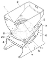
図1乃至図6等において、コイン送出装置であるコインホッパ装置1は、コインCをバラ積み状態で保留するホッパヘッド2と、該ホッパヘッド2を載置するための上面が傾斜している基台3と、前記ホッパヘッド2の内底部に回転自在に設けられたコインの送り出し用の回転ディスク4と、前記回転ディスク4の直下に配設され、回転ディスク4により送られるコインCを受けて、回転ディスク4の周辺部の適宜な位置に設けた送出口にスライド移動し案内するためのガイド板5を含んでいる。
ガイド板5はこの場合、前記基台3の傾斜上面にネジによって取り付け固定した矩形状のベース板である。ガイド板5であるベース板は基台上面に傾斜設置され、その上に前記ホッパヘッド2がその下端部に設けてある矩形の底板6を介して取り付け固定されている。前記ホッパヘッド2の底板6の4隅角部にはだるま状の取り付け孔7が設けられており、図示しないネジを、だるま状の取り付け孔7の径大孔部から挿入し、径小孔部に移動させてネジ止めすることで、ホッパヘッド2を装着固定することができる。またホッパヘッド2は、ネジにだるま状取り付け孔7の径大孔が合致する方向に回動操作することで、上方に抜き出し取り外せるようになっている。
1 to 6, etc., a
In this case, the
前記回転ディスク4の周辺部には、円形状のコインを受け入れるための通孔8が等間隔に複数個形成されており、ホッパヘッド2内のコインCはこれらの通孔8に回転ディスク4の回転に伴って落ち込み取り込まれるようになっている。通孔8の下端周縁の近傍には、図示しないが、回転ディスクが回転した時に、コインCを押し進めるための突片状のコイン押進部が下向きに突出形成されている。
回転ディスク4の回転によって、ホッパヘッド2内のコインCは掻き回されて通孔8内に落ち込む。落ち込んだコインCは、通孔8に保持された状態で前述のコイン押進部で押されガイド板5上を、図1で時計方向に送られ、同図で右手前の下方域から左方中間の上方域にと移動するように送られる。そのコインCが移動した前述の左方中間の上方域付近に、コインの送出口が設けられている。コインの送出口は、ホッパヘッド2における回転ディスク4を取り囲むように下に延びている筒状壁部2dの周面の一部を帯状の矩形口に切り欠きけ形成することで設けることができる。
A plurality of through
As the
さて次に本発明の要部となる、回転ディスク4の構造について説明する。
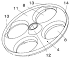
回転ディスク4は所定厚みの円形の本体部11を有し、その円形の本体部11の中心部に回転ディスク駆動用の駆動軸(図示せず)と嵌合するボス部12が突設され、そのボス部12を中心としてその周りに前述した複数個の円形の通孔8が等間隔に穿設形成されている。
ここで回転ディスク4はその外周部に、ぐるりと環状に全体を取り囲むように、内側が斜面部13となっている突出縁14が一体に突出形成されている。前記斜面部13は、下に向かうほど縮径するように形成した下向きの傾斜面である。
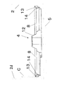
そして、突出縁14の外側面16は、図6に示すように垂直に立った平滑な外側面16hとなっている。
従って、突出縁14は図2、図4、図6等に示すように、断面直角三角形状で、回転ディスク4の外周縁部にリング状に存在し、内側が傾斜した斜面部13となっている構造の突出縁14である。
突出縁は斜面部であるので、回転ディスクの回転でその外側周辺を動き回されるコインがこの斜面部の近くに来ても、斜面部に乗ることはない。
むしろ、前記突出縁14の傾斜面である斜面部13は、コインCに対し滑り面として作用し、回転ディスク4の外周部周辺で周方向に回転移動するコインCを回転ディスク4の回転中心の方へと滑らせように機能する。
すなわち、傾斜部13は回転ディスク4の外周部近辺で、ホッパヘッド2の筒状壁部2dの内面にもたれかかってコイン立ちししようとしても、直ぐにそのコインCを、回転ディスク4の中心方向へ滑らせて、コイン受け孔8に落ち込ませる案内部となるのである。
Next, the structure of the
The
Here, the
The outer surface 16 of the protruding
Accordingly, as shown in FIGS. 2, 4, 6 and the like, the protruding
Since the protruding edge is a slope portion, even if a coin that moves around the outer periphery by the rotation of the rotating disk comes near the slope portion, it does not get on the slope portion.
Rather, the
That is, the
このように回転ディスク4の外周辺部で全周に突出してある前記突出縁14は、回転ディスク4の盤面上において、図3に示すように上方より視ると、その一部が円孤状になって通孔8の回転ディスク4の外周縁部と重なるように位置するものとなっている。すなわち、通孔8の最も外側の孔縁部分の上に傾斜部13が位置するものとなっている。
As described above, the protruding
このように回転ディスク4の盤面上において、コインCが通孔8の外側周辺部分(外縁)で、従来の図7に示すように乗っていた縁部(リブ)を残さないように、その部分に、環状で内側が下向き傾斜面となっている傾斜部13を立設させることにより、その縁部を無くした構造としてある。
In this way, on the surface of the
従ってこの内側が傾斜面となっている突出縁14の存在によって、コインCが回転ディスク4の通孔8に位置したときに、従来のようにコインがホッパの筒状壁部2dにもたれかかりながら、通孔8の孔周辺部で立つことができなくなり、突出縁14の傾斜内面によって、すなわち傾斜部13によって通孔8内へ確実に滑り落とされて行く。
Therefore, when the coin C is positioned in the through
これにより、コインCが通孔8に捕捉される捕捉率が高まり、回転ディスクはコインCをスピーディに払い出すようになって払い出し能力が向上する。
なお、傾斜部13、すなわち突出縁14は少なくとも通孔8の最も外側の周縁部分に存在するように回転ディスク4の外周部に設けられているものであれば、従来の問題点であったコイン立ちを抑えることができる。
As a result, the capture rate at which the coin C is captured in the through
If the
しかし実施例のように、回転ディスク4の外周部全体を取り囲むように全周に立設形成されている構成の方が、部分的に傾斜部13すなわち突出縁14を形成するよりは、製造コストが安価で、製作も容易で有利なので全周に形成するのが実際的で好ましい。
また突出縁14が回転ディスク4の全周にあれば通孔8以外の処の突出縁14の部分でも、すなわち通孔8と通孔8との間に位置する処の突出縁14でも、そこに移動して来て位置したコインCが突出縁14の内面傾斜により回転ディスク4の外周側から内側中心方向へ向かわされるようになるので、回転ディスク4の回転によるコインの連れ回り動作と相俟って通孔8へ落とし込まれる確率がより高くなり、コインCの捕捉が促進される相乗効果が期待できることからも全周にある方が好適である。
However, as in the embodiment, the construction in which the entire circumference of the
In addition, if the protruding
以上のように、回転ディスク4の外周辺部に内側が下向きの傾斜面となっている傾斜部13を設けることで、通孔8の外周縁部でコイン立ちする骨部(余地部)を消失させる構成とすることができ、コイン立ちが出来ないようにすることができる。またそのための手段も内面傾斜の突出縁14を形成するだけの極めて簡易な対応で達成することができる。
よって、本構成によって、コインCが間断なく連続して通孔8に落ち込み、コインの捕捉率が高まり、コインを安定して、かつ高効率で払い出し処理できるコインホッパの回転ディスクを得ることができる。
As described above, by providing the
Therefore, according to this configuration, the coin C can continuously fall into the through
図1は、実施例の回転ディスクが使用されるコインホッパの斜視図である。
図2は、実施例の回転ディスクの斜視図である。
図3は、実施例の回転ディスクの平面図である。
図4は、実施例の回転ディスクの図3におけるA−A断面図である。
図5は、実施例の回転ディスクを内挿したコインホッパのコイン取り込みの様相も併せて示したコインホッパの要部側面断面図である。
図6は、図4におけるB部の部分断面図である。
図7は、従来構造のコインホッパを、コイン立ちの問題と共に説明して示した側面断面図である。
図8は、従来構造の回転ディスクの平面図である。
図9は、従来の構造によるコイン立ちの問題を解決したタイプのコインホッパを示す側面断面図である。
FIG. 1 is a perspective view of a coin hopper in which the rotating disk of the embodiment is used.
FIG. 2 is a perspective view of the rotating disk of the embodiment.
FIG. 3 is a plan view of the rotating disk of the embodiment.
4 is a cross-sectional view of the rotary disk according to the embodiment, taken along line AA in FIG.
FIG. 5 is a side cross-sectional view of the main part of the coin hopper, which also shows an aspect of the coin hopper taking in the coin hopper with the rotating disk of the embodiment inserted therein.
6 is a partial cross-sectional view of a portion B in FIG.
FIG. 7 is a side cross-sectional view illustrating a conventional coin hopper together with a problem of coin standing.
FIG. 8 is a plan view of a conventional rotating disk.
FIG. 9 is a side sectional view showing a coin hopper of the type that solves the problem of coin standing due to the conventional structure.
C コイン
1 コインホッパ
4 回転ディスク
5 ガイド板
8 通孔
13 斜面部
14 突出縁
Claims (2)
前記回転ディスクには、コインを前記通孔へと誘導落下させる斜面部が回転ディスクの外周縁部に立設形成されていることを特徴とするコインホッパの回転ディスク。 A hopper head installed on a base placed at the top of the hopper main body, in which coins are held in a stacked state, and a plurality of through holes that are rotatably disposed on the inner bottom portion of the hopper head to allow coins to fall A rotating disk formed circumferentially around the periphery and a lower part of the rotating disk so that the coin received in the through hole is slidably guided to the coin outlet by the pushing protrusion when the rotating disk rotates. In a coin hopper provided with a guide plate arranged in
A rotating disk for a coin hopper, wherein the rotating disk is provided with a slope portion for guiding and dropping a coin into the through hole at an outer peripheral edge of the rotating disk.
The inclined portion is a protruding edge formed on an inclined surface having a downwardly inclined inner side that is connected to the outermost edge of the through hole so as to surround the rotating disk in a ring shape. The rotating disk of the coin hopper according to claim 1.
Priority Applications (1)
| Application Number | Priority Date | Filing Date | Title |
|---|---|---|---|
| JP2008015860A JP2009176181A (en) | 2008-01-28 | 2008-01-28 | Rotating disk of coin hopper |
Applications Claiming Priority (1)
| Application Number | Priority Date | Filing Date | Title |
|---|---|---|---|
| JP2008015860A JP2009176181A (en) | 2008-01-28 | 2008-01-28 | Rotating disk of coin hopper |
Publications (2)
| Publication Number | Publication Date |
|---|---|
| JP2009176181A true JP2009176181A (en) | 2009-08-06 |
| JP2009176181A5 JP2009176181A5 (en) | 2011-03-10 |
Family
ID=41031170
Family Applications (1)
| Application Number | Title | Priority Date | Filing Date |
|---|---|---|---|
| JP2008015860A Pending JP2009176181A (en) | 2008-01-28 | 2008-01-28 | Rotating disk of coin hopper |
Country Status (1)
| Country | Link |
|---|---|
| JP (1) | JP2009176181A (en) |
Cited By (1)
| Publication number | Priority date | Publication date | Assignee | Title |
|---|---|---|---|---|
| JP2022019293A (en) * | 2020-07-17 | 2022-01-27 | 山佐株式会社 | Game machine |
Citations (4)
| Publication number | Priority date | Publication date | Assignee | Title |
|---|---|---|---|---|
| JPS5473800U (en) * | 1977-11-01 | 1979-05-25 | ||
| JPS57123569U (en) * | 1981-01-23 | 1982-08-02 | ||
| JPS6327970U (en) * | 1986-08-07 | 1988-02-24 | ||
| JPH0785333A (en) * | 1993-09-14 | 1995-03-31 | Universal Hanbai Kk | Hopper device |
-
2008
- 2008-01-28 JP JP2008015860A patent/JP2009176181A/en active Pending
Patent Citations (4)
| Publication number | Priority date | Publication date | Assignee | Title |
|---|---|---|---|---|
| JPS5473800U (en) * | 1977-11-01 | 1979-05-25 | ||
| JPS57123569U (en) * | 1981-01-23 | 1982-08-02 | ||
| JPS6327970U (en) * | 1986-08-07 | 1988-02-24 | ||
| JPH0785333A (en) * | 1993-09-14 | 1995-03-31 | Universal Hanbai Kk | Hopper device |
Cited By (1)
| Publication number | Priority date | Publication date | Assignee | Title |
|---|---|---|---|---|
| JP2022019293A (en) * | 2020-07-17 | 2022-01-27 | 山佐株式会社 | Game machine |
Similar Documents
| Publication | Publication Date | Title |
|---|---|---|
| JP2014120015A (en) | Coin hopper | |
| JP2011233067A (en) | Coin hopper | |
| JP2009176181A (en) | Rotating disk of coin hopper | |
| JP2009176181A5 (en) | ||
| JP4714865B2 (en) | Game medium shooting device in game medium lending machine | |
| JP2007244806A (en) | Put-out device for game machine | |
| JP5035854B2 (en) | Game machine | |
| JP2005296462A (en) | Ball delivery device of game machine | |
| JP2004310408A (en) | Coin dispenser device | |
| JP2009123065A (en) | Coin throwing device | |
| JP2006271526A (en) | Ball putting out device and game machine | |
| JP2004086633A (en) | Hopper for disk | |
| JP2006055551A (en) | Game machine | |
| JP3723147B2 (en) | Lifting-type medal delivery device | |
| JP2010224598A (en) | Token dispenser | |
| JP2005329069A (en) | Ball feeding device | |
| JP2015229092A (en) | Game machine | |
| JP2005309848A (en) | Coin feeding device | |
| JP2009153929A (en) | Ball putout device of game machine | |
| JP2007272512A (en) | Overflow chute device for coin reservation device | |
| JP5162044B1 (en) | Hopper device | |
| JP5453029B2 (en) | Banknote / ticket separator | |
| JP2005000240A (en) | Ball output device | |
| JP2003123112A (en) | Coin paying-out device | |
| JP2009160220A (en) | Game ball putout device in game machine |
Legal Events
| Date | Code | Title | Description |
|---|---|---|---|
| A521 | Written amendment |
Free format text: JAPANESE INTERMEDIATE CODE: A523 Effective date: 20110120 |
|
| A621 | Written request for application examination |
Free format text: JAPANESE INTERMEDIATE CODE: A621 Effective date: 20110120 |
|
| A977 | Report on retrieval |
Free format text: JAPANESE INTERMEDIATE CODE: A971007 Effective date: 20121126 |
|
| A131 | Notification of reasons for refusal |
Free format text: JAPANESE INTERMEDIATE CODE: A131 Effective date: 20121128 |
|
| A02 | Decision of refusal |
Free format text: JAPANESE INTERMEDIATE CODE: A02 Effective date: 20130321 |