JP2009155871A - Temporary toilet - Google Patents
Temporary toilet Download PDFInfo
- Publication number
- JP2009155871A JP2009155871A JP2007334036A JP2007334036A JP2009155871A JP 2009155871 A JP2009155871 A JP 2009155871A JP 2007334036 A JP2007334036 A JP 2007334036A JP 2007334036 A JP2007334036 A JP 2007334036A JP 2009155871 A JP2009155871 A JP 2009155871A
- Authority
- JP
- Japan
- Prior art keywords
- water
- pump
- electric pump
- pipe
- water supply
- Prior art date
- Legal status (The legal status is an assumption and is not a legal conclusion. Google has not performed a legal analysis and makes no representation as to the accuracy of the status listed.)
- Pending
Links
Images


Abstract
Description
この発明は、設置場所の電気環境に適応可能な水洗式の仮設トイレに関する。 The present invention relates to a flush-type temporary toilet that can be adapted to the electrical environment of an installation location.
現在、工事現場やイベント会場などの、一時的にトイレを必要とするが将来的には不要になる箇所では、移動式の仮設トイレが多く用いられている。また、公園、河川敷、登山道、海浜公園、キャンプ場などの屋外施設において、建築物としての常設トイレを設置することが難しい場所でも同様の移動式の仮設トイレが多く設置されている。 Currently, mobile temporary toilets are often used in construction sites and event venues where toilets are needed temporarily but are not needed in the future. Also, in outdoor facilities such as parks, riverbeds, mountain trails, beach parks, campsites and the like, there are many similar mobile temporary toilets even in places where it is difficult to install permanent toilets as buildings.
従来はこのような仮設トイレとして、汚物を直接汚物タンクに落とすくみ取り式のものが多く用いられていたが、近年、衛生上の理由から水洗式のものが用いられるようになっている。しかし、仮設トイレの設置環境では水の使用量が限られる場合が多いために、便器の上方に水槽を設け、そこから洗浄水を落下させる落下式のような大量の水を使用する方式は利用しにくく、限られた量の水をポンプで送り出すことが多い。例えば、特許文献1に記載のように、足踏みポンプを用いたトイレが利用されている。
Conventionally, as such a temporary toilet, a sink type that drops filth directly into a filth tank has been used, but recently, a flush type has been used for hygienic reasons. However, because the amount of water used is often limited in the installation environment of temporary toilets, a method that uses a large amount of water, such as a drop type that drops a wash water from a water tank above the toilet, is used. It is difficult to pump and often pumps a limited amount of water. For example, as described in
このトイレでは、人力で動かす足踏みポンプはある程度の力を必要とするため、非力な子供だと十分に水を流すことができない場合がある。このため、電気が整っているところでは、当然電気を利用してポンプを動かすことが利便性の面から好ましい。一方で、仮設トイレを設置する環境は、電気が通じていない環境であることも多い。このため、特許文献2のような、太陽電池を用いて仮設トイレに電気を確保するといったことが行われている。
In this toilet, a foot pump that is driven by human power requires a certain amount of force, so that a weak child may not be able to flow water sufficiently. For this reason, naturally, it is preferable from the viewpoint of convenience that the pump is moved using electricity. On the other hand, the environment where a temporary toilet is installed is often an environment where electricity is not connected. For this reason, as in
しかしながら、従来の仮設トイレでは、電気が整った箇所で用いられることを前提に作ったものは少ない。しかも電気を利用する仮設トイレは、電気がある環境でしか利用できないという問題があった。 However, there are few conventional temporary toilets on the premise that they are used in places where electricity is prepared. Moreover, there is a problem that a temporary toilet using electricity can only be used in an environment where electricity is available.
このため、先の設置場所で不要になった仮設トイレを別のところに移動させて利用しようとしても、それが電気の利用を前提としたものであれば、電気の通じていないところに持って行くことはできず、電気の利用を前提としていないものであれば、電気の通じたところに持って行っても電気を利用することができなかった。従って、電気がある場合には電気を利用できるようにするならば、電気設備の有無ごとに適した仮設トイレを別個に用意しなければならなかった。 For this reason, even if you try to move the temporary toilet that is no longer needed at the previous installation location to another location, if it is based on the use of electricity, bring it to a place where electricity is not connected. I couldn't go, and I couldn't use electricity even if I took it to a place where electricity was available if it was not premised on the use of electricity. Therefore, if electricity can be used in the presence of electricity, a temporary toilet suitable for each electric equipment must be prepared separately.
さらに、工事現場などで仮設トイレの設置中に周辺の環境が整い、電気が利用できるようになったとしても、電気の利用を前提としていない仮設トイレではその電気を使用することができなかった。 Furthermore, even if the surrounding environment was prepared and electricity could be used while installing a temporary toilet at a construction site or the like, the electricity could not be used in a temporary toilet that does not assume the use of electricity.
一方で、特許文献2に記載のように仮設トイレに太陽電池を用いれば、周辺の送電環境にかかわらず電気を用いることができる。しかし、太陽電池が高価であるために、仮設トイレの設置コストに見合わず、電気の有無に合わせた二種類の仮設トイレを用意した方がよいことになってしまった。また、太陽電池でポンプを駆動できるだけの電気容量を確保することは容易ではなく、さらに、曇天雨天が続くと利用できなくなるという問題点もあった。
On the other hand, if a solar cell is used for a temporary toilet as described in
そこでこの発明は、水洗式の仮設トイレを、設置場所の電気の有無に関わらず汎用的に用いることができ、送電された後は設備を取り替えることなく電気を利用できるようにすることを目的とする。 Therefore, the present invention has an object to make it possible to use a flush-type temporary toilet universally regardless of the presence or absence of electricity at the place of installation, and to use electricity without changing equipment after power transmission. To do.
この発明は、便器を水洗するための洗浄水を供給する洗浄管と、洗浄水を蓄える貯水タンクを有する移動可能な仮設トイレを、人力により前記貯水タンクから前記洗浄管に洗浄水を送る人力ポンプと、電気駆動により前記貯水タンクから前記洗浄管に洗浄水を送る電動ポンプとを備えたものにすることで、電気の有無に関わらず利用可能としたのである。
すなわち、送電された環境では電動ポンプを用い、送電されていない環境では人力ポンプを用いることで、いずれの場合にも水洗できるようにしている。
The present invention relates to a human-powered pump for manually supplying a movable temporary toilet having a washing pipe for supplying washing water for washing a toilet bowl and a water storage tank for storing the washing water from the water storage tank to the washing pipe. And an electric pump that sends cleaning water from the water storage tank to the cleaning pipe by electric drive, so that it can be used with or without electricity.
That is, the electric pump is used in an environment where power is transmitted, and the human power pump is used in an environment where power is not transmitted, so that water can be washed in either case.
人力ポンプ及び電動ポンプから便器へ洗浄水を供給する洗浄管は、それぞれのポンプごとに一本ずつ設けていてもよいが、それぞれのポンプからの送水管同士を合流させ、その合流管を、便器に設けた一つの洗浄管に接続すると、便器の構造を簡略化することができる。この場合、電動ポンプからの送水管に、その電動ポンプへの逆流を防止する逆止弁を設けておくことで、十分な水圧を確保することが難しい人力ポンプの操作時に、水流が電動ポンプ側に流れ込んでしまって水圧がさらに低下し、洗浄水の勢いが低下することを防ぐ。 One washing pipe for supplying washing water from the human-powered pump and the electric pump to the toilet bowl may be provided for each pump, but the water feeding pipes from each pump are joined together, and the joining pipe is connected to the toilet bowl. If it is connected to one washing tube provided in the toilet, the structure of the toilet can be simplified. In this case, by installing a check valve in the water supply pipe from the electric pump to prevent the backflow to the electric pump, the water flow is not This prevents the water pressure from further flowing into the water and further reducing the water pressure.
上記の逆止弁を設ける箇所は、電動ポンプへの逆流を防止出来る箇所であれば特に制限されない。このとき、逆止弁として非電動のものを用いることで、電源が無くても逆止弁が作用して逆流を防ぎ、便器を洗浄する水圧が低下することを抑制できる。 The location where the above-described check valve is provided is not particularly limited as long as it can prevent backflow to the electric pump. At this time, by using a non-electric check valve as the check valve, it is possible to prevent the check valve from acting even if there is no power source to prevent the back flow and to reduce the water pressure for washing the toilet.
なお、電動ポンプによる水圧は人力ポンプによる水圧よりも高いので、ある程度人力ポンプに逆流しても便器を洗浄する水圧は必要程度を確保できるが、逆流すると水圧の低下は避けられない。そこで、人力ポンプからの送水管にも非電動の逆止弁を設けておくと、電動ポンプを使用した際に人力ポンプに逆流して水圧が低下することを抑制できる。 In addition, since the water pressure by the electric pump is higher than the water pressure by the human-powered pump, the water pressure for washing the toilet can be ensured to a necessary level even if it flows backward to the human-powered pump to some extent. Therefore, if a non-electric check valve is also provided in the water supply pipe from the human-powered pump, it is possible to suppress the water pressure from flowing back to the human-powered pump when the electric pump is used.
上記のそれぞれのポンプからの送水管の合流を三方口継手で行い、その継手を逆止弁構造とすると、送水管の合流と逆止弁による逆流防止とを一つの部品で行うことができ、構造が簡略化され、製造が容易となる。この場合、三方口継手のうち、電動ポンプからの送水管を接続した口部に逆止弁を設けると、電動ポンプへの逆流を防止する以外の副作用を起こさずに済み、効率良く水圧の制御ができる。なお、三方口継手の構造は、Y字型でもよいし、T字型でもよい。 When the water pipes from each of the above pumps are merged with a three-way joint, and the joint is a check valve structure, the water pipe can be merged and the check valve can be used to prevent back flow with a single component. The structure is simplified and manufacturing is easy. In this case, if a check valve is provided at the port connected to the water supply pipe from the electric pump among the three-way joints, there is no side effect other than preventing back flow to the electric pump, and the water pressure is controlled efficiently. Can do. The structure of the three-way joint may be Y-shaped or T-shaped.
上記三方口継手に設ける非電動の逆止弁の具体的な構造としては、電動ポンプからの送水管を接続した筒状口部に弁座を形成し、その弁座に接離する弁体を装填したものが挙げられる。これは、三方口継手がT字型でもY字型でもとりうる構造だが、特にT字型の三方口継手の場合に有効な逆止弁として働く。人力ポンプのみから水流が来た場合には、弁体が弁座に収まり、電動ポンプへの水流を遮ることができる。より具体的には、弁体を球形にすることで、弁座に嵌りやすくすることができる。また、その球形の弁体が他の口部に移動することを阻止する突起を上記三方口継手内に設けることで、弁体が他の口部に移ってしまい適切に弁座に収まらなくなることを防ぐことができる。例えば、弁体が合流管側の口部に移動してしまうと、人力ポンプからの水流によって弁座に収まるのではなく、洗浄管に繋がる合流管を遮ってしまうことになってしまうが、前記突起により、このような事態を防ぐことができる。 As a specific structure of the non-electric check valve provided in the above three-way joint, a valve seat is formed in a cylindrical mouth portion connected to a water supply pipe from an electric pump, and a valve body that contacts and separates from the valve seat is provided. One loaded. This is a structure in which the three-way joint can be T-shaped or Y-shaped, but it works as an effective check valve particularly in the case of a T-shaped three-way joint. When the water flow comes only from the human-powered pump, the valve body is accommodated in the valve seat, and the water flow to the electric pump can be blocked. More specifically, by making the valve body spherical, it can be easily fitted into the valve seat. Also, by providing a projection in the three-way joint that prevents the spherical valve body from moving to the other mouth, the valve body moves to the other mouth and does not fit properly in the valve seat. Can be prevented. For example, if the valve body moves to the mouth portion on the merging pipe side, it will not fit in the valve seat by the water flow from the human power pump, but will block the merging pipe that leads to the washing pipe, Such a situation can be prevented by the protrusion.
なお、人力ポンプからの送水管にも逆止弁を設ける場合には、人力ポンプからの送水管を接続した筒状口部にも弁座を形成し、上記突起によって区切られた人力ポンプ側に弁体を設けると、上記と同様の動作により、人力ポンプへの逆流を抑制できる。 When a check valve is also provided on the water supply pipe from the human power pump, a valve seat is also formed on the cylindrical mouth portion to which the water supply pipe from the human power pump is connected. When the valve body is provided, the backflow to the human power pump can be suppressed by the same operation as described above.
上記人力ポンプの構造は特に限定されず、手で作動させるものでも、足で作動させるものでもよい。その中でも、ペダルの踏み込みにより作動させるフットポンプとすると、人間の体重を効率よく掛けて強い力で洗浄水を吐出させることができるので好ましい。一方で、上記電動ポンプを作動させるには、電気的なスイッチの入力だけでよいので、電動ポンプの作動スイッチの形態は特に限定されない。ただし、人力ポンプのペダルを踏み込むことで電動ポンプのスイッチが入り電源が供給されるようにすると、操作系を一つにまとめることができ、仮設トイレ内の構成を簡素化できるので好ましい。 The structure of the above-mentioned human power pump is not particularly limited, and it may be operated by hand or operated by foot. Among these, it is preferable to use a foot pump that is operated by depressing a pedal, because the washing water can be discharged with a strong force by applying a human weight efficiently. On the other hand, in order to operate the electric pump, it is only necessary to input an electric switch. Therefore, the form of the operation switch of the electric pump is not particularly limited. However, it is preferable that the electric pump is switched on and the power is supplied by depressing the pedal of the human-powered pump because the operation system can be integrated into one and the configuration in the temporary toilet can be simplified.
この場合、ペダルの踏み込み後すぐにスイッチが入るようになっていると、誤ってペダルに触れただけで電動ポンプのスイッチが入ってしまうことがあるが、ペダルを可動部分全体の1割〜2割程度踏み込んだところで電動ポンプのスイッチが入るようにすると誤作動の可能性を抑えることができる。また、電動ポンプのスイッチが入る箇所よりもペダルを踏み込まないようにするストッパーを取り付けられるようにし、電源供給時にはこのストッパーを設けておくと、それ以上人力ポンプが作動しなくなるので、洗浄水を余分に浪費することを抑えられる。 In this case, if the switch is turned on immediately after the pedal is depressed, the electric pump may be turned on just by accidentally touching the pedal. If the electric pump is switched on when it is depressed by about a half, the possibility of malfunction can be suppressed. In addition, it is possible to attach a stopper that prevents the pedal from being depressed more than the point where the electric pump is switched on, and if this stopper is provided when supplying power, the human-powered pump will not operate any more, so extra washing water will be required. Can be avoided.
なお、貯水タンクへの給水については、上水道に接続可能な開閉弁を設けておき、この開閉弁を貯水タンク内に設けたボールタップによって開閉するようにすることで、電源の有無に関わらず、貯水タンクへの供給を制御することができる。また、貯水タンクへバケツなどで直接給水可能な給水口を設けておくと、上水道が使えない箇所でも上記仮設トイレを利用できる。 For water supply to the water storage tank, an open / close valve that can be connected to the water supply system is provided, and this open / close valve is opened and closed by a ball tap provided in the water storage tank, regardless of whether there is a power supply or not. The supply to the tank can be controlled. In addition, if a water supply port that can supply water directly to the water storage tank with a bucket or the like is provided, the temporary toilet can be used even in a place where the water supply cannot be used.
また、便器使用後の汚水を一時貯める汚水タンクを上記便器の下方に設けることで、汚水の一時的な蓄積が可能となる。さらに、汚水タンクの下部及び背部に蓋付きのドレーンを設けておくと、電源の供給が無い場合でもそれらのドレーンを通じて、仮設トイレの下部や後方に設けた外部汚水タンクや、間近にある下水道へ落下させることで排水が可能となる。一方で、汚水タンク内に電動の汚水ポンプを設けておくと、電源の供給がある場合には強制排水させて、離れた箇所にある外部汚水タンクや下水道へ汚水を送り込むことができる。これらのドレーンと汚水ポンプとの両方を設けておくことで、電源が無い場合にはドレーンを用いて排水し、電源がある場合には汚水ポンプを用いて仮設トイレから離れた箇所まで排水できる。これにより、汚水タンク内に残る残留物の量を抑えることができる。 Moreover, temporary accumulation of sewage becomes possible by providing a sewage tank that temporarily stores sewage after use of the toilet bowl below the toilet. In addition, if drains with lids are provided at the bottom and back of the sewage tank, even if there is no power supply, the drains can be connected to external sewage tanks at the bottom or rear of the temporary toilet, or to the nearby sewer. Draining is possible by dropping. On the other hand, if an electric sewage pump is provided in the sewage tank, forcible drainage can be performed when power is supplied, and sewage can be sent to an external sewage tank or sewer at a remote location. By providing both of these drains and the sewage pump, when there is no power source, drainage is performed using the drain, and when there is a power source, drainage can be performed using a sewage pump to a location away from the temporary toilet. Thereby, the quantity of the residue which remains in a sewage tank can be suppressed.
この発明に係る仮設トイレは、設置場所に電気が通っているか否かに関わらず用いることができるとともに、電気が通っていればその電気を利用できる。運用者は送電状況に関わらず設置できるので、送電状況ごとに別個のトイレを用意することなく、利用者が最大限電源による恩恵を受けられるようにすることができる。また、送電されていない箇所での設置中に送電がされるようになった場合は、ユニットの交換を行うことなく、そのままの状態で電気を利用してより快適に利用できる。 The temporary toilet according to the present invention can be used regardless of whether electricity passes through the installation place, and can use the electricity if electricity passes. Since the operator can install regardless of the power transmission status, the user can receive the maximum benefit from the power source without preparing a separate toilet for each power transmission status. In addition, when power is transmitted during installation at a location where power is not transmitted, it is possible to use electricity more comfortably without changing the unit.
以下、この発明にかかる仮設トイレの実施形態を、添付図面を用いて説明する。
図1に実施形態にかかる仮設トイレの概略を示す。正面に扉1があり、それ以外の三方は壁2で覆われ、一つのユニットとなっている。扉1を開けると、内には仮設トイレの設置場所より高くなった床部3があり、その奥にユニット本体4が取り付けてある。
Embodiments of a temporary toilet according to the present invention will be described below with reference to the accompanying drawings.
FIG. 1 shows an outline of a temporary toilet according to the embodiment. There is a
図2は、ユニット本体4の主な構成を示す。土台ともなるマルチタンク11の上に、踏み板でもあるマルチタンク蓋12が乗り、その蓋の手前側中央部に空いた穴にプラスチック製の便器13が嵌る。これらが一体となって、ユニット本体4を形成する。設置時には床部3からマルチタンク蓋12までが段になり、正面からは残量窓16が確認でき、後述するペダル32が床部3の上に突き出ている。
FIG. 2 shows a main configuration of the
図3は、マルチタンク11内を上方から見た平面図を示す。マルチタンク11の左右方向中央部には汚水タンク21が収めてあり、これが便器13から出た汚水を受ける汚水タンク室となる。汚水タンク21で区切られた左右の区画は使用前の水を蓄える貯水タンク22、22’となる。汚水タンク21の下には、マルチタンク11の底面との間に隙間24が設けてあり、この隙間24が左右の貯水タンク22、22’間を繋いで一体のものとしている。右側の貯水タンク22’の手前側には、後述する人力ポンプ31を収める人力ポンプボックス23を収める。
FIG. 3 is a plan view of the inside of the multi-tank 11 as viewed from above. A
上記のマルチタンク11、汚水タンク21,人力ポンプボックス23はいずれもプラスチック製であり、水の侵入及び漏出を防ぐ。
The multi-tank 11, the
図4は、マルチタンク11の正面図を示す。人力ポンプボックス23を収めるマルチタンク11の右側正面には、人力ポンプ31を動作させる可動部分であるペダル32を手前側に通すための縦スリット15が空いている。図示しないが、人力ポンプボックス23にも、マルチタンク11に空いている縦スリット15と合わさる位置に、ペダル32を通すための縦スリットが設けてある。また、これらの縦スリットに貯水タンク22,22’から水が通らないように、人力ポンプボックス23とマルチタンク11とは水を通さないように接着している。さらに、マルチタンク11の左側正面には、貯水タンク22の水位を外部から確認するための残量窓16が取り付けてある。
FIG. 4 shows a front view of the multi-tank 11. A
図5は、マルチタンク11の背面図を示す。汚水タンク21が収まる中央部には、下部に汚水を重力によって排出する汚水排水用ドレーン17が設けてあり、汚水タンク21内まで直結している。また、それとは別に、後述する汚水ポンプ51から排出される汚水の出口となるポンプ排出口18が設けてある。さらに、図5では右側となる、マルチタンク11の貯水タンク22の背面に、給水のための上水道管と接続可能である水道直結用ボルト19が設けてある。
FIG. 5 shows a rear view of the multi-tank 11. In the central part where the
図6は、マルチタンク蓋12と便器13とをマルチタンク11に載せた状態、すなわち、使用状態におけるユニット本体4の上方からの平面図を示す。マルチタンク蓋12には、貯水タンク22に繋がる給水口25が設けてあり、給水口蓋26で覆ってある。バケツや給水車から給水する際には給水口蓋26を外して、給水口25から貯水タンク22に給水する。
FIG. 6 shows a plan view from above of the unit
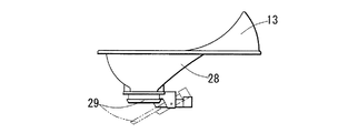
便器13の内部奥には洗浄のための水流を吐き出す洗浄水吐水ノズル27が一つ設けてあり、電源供給の有無に関わらずここから便器13内へ洗浄水aが吐水される。また、便器13の中央部には下方への落下孔28が空いている。洗浄水吐水ノズル27の吐き出し方向は、落下孔28に向いておらず、落下孔28に向かって落ち込む落下孔28の周辺の傾斜部に向いている。このため、吐出された水はすぐには落下孔28に落ちず、落下孔28周辺を周回して洗浄してから落ちる。
A flush
図7は、便器13のみの側面図を示す。上記の落下孔28は、普段は下方からフラッパー29で塞がっている。このフラッパー29は上面に乗った重量によって一時的に下に向かって開き、糞尿や汚水を汚水タンク21へ落下させることができ、落下後はバネによって自動的に閉まり、汚水タンク21から臭いが上がってくるのを防ぐ。
FIG. 7 shows a side view of only the
図8は、マルチタンク11内の、汚水タンク21,貯水タンク22,22’、人力ポンプボックス23に設ける設備及び配線配管図を示す。
FIG. 8 shows equipment and wiring piping diagrams provided in the
図9は、人力ポンプボックス内23の横断面図を示す。人力ポンプボックス23内には人力ポンプ31が設けてある。この人力ポンプ31は、上記の縦スリット15を通してマルチタンク11の手前側に突き出たペダル32を踏み込むことで作動する。作動すると、人力ポンプボックス23より奥側、すなわち貯水タンク22’内へ延びた吸水管33から貯水タンク22’内の水を取り込み、マルチタンク11の奥側へ延びる第一送水管34へ水を送り出す。この第一送水管34は、後述する三方口継手35に繋がる。
FIG. 9 shows a cross-sectional view of the inside 23 of the human-powered pump box. A
左側の貯水タンク22内には、電動ポンプ37が設けてある。この電動ポンプ37は、貯水タンク22内の水を電気駆動で第二送水管36を通じて後述する三方口継手35へ送り出す。この電動ポンプ37を作動させるスイッチ38は、人力ポンプボックス23内の人力ポンプ31の可動部分に取り付けてあり、電動ポンプ37とは入力を伝える信号ケーブル39で繋がっている。電源ケーブル41から電気が供給されている場合は、上記ペダル32が踏み込まれると、その途中でスイッチ38が入り、電動ポンプ37が作動して、第二送水管36を通じて貯水タンク22内の水を所定量だけ三方口継手35へ送る。なお、このとき、人力ポンプ31も動作することになるが、踏み込みの半ばで電動ポンプ37が十分に送水を行うことになるので、最後まで踏み込む必要がない。スイッチ38が入る途中の位置は、ペダル32の可動し始めから可動範囲の1〜2割程度の箇所であると、誤ってペダル32に触れた際に電動ポンプ37が誤作動することを抑制できる。
An
なお、電源供給時には、ペダル32を踏み込んでスイッチ38が入った後、それ以上は踏み込まないようにする箇所に、ストッパー49(図9内に破線で図示する。)を取り付ける。これにより、使用者はペダル32を最後まで踏み込むことがなくなり、人力ポンプ31から余分な水が送り出されることを防ぎ、水を節約することができる。
When power is supplied, a stopper 49 (shown by a broken line in FIG. 9) is attached to a place where the
図10は、三方口継手35の断面図を示す。人力ポンプ31から第一送水管34を通じて送り込まれる流路と、電動ポンプ37から第二送水管36を通じて送り込まれる流路とが、この三方口継手35で合わさり、一本の合流管40の流路となって、洗浄水吐水ノズル27へ通じる洗浄管42へ送り出される。二つの流路が合わさるところには突起43が設けてあり、突起43と第二送水管36との間に、止水用のボールである弁体44が入っている。弁体44は突起43によって動く範囲を制限され、第一送水管34側の筒状口部46や、合流管40側の筒状口部48に移ることはない。
FIG. 10 shows a cross-sectional view of the three-way joint 35. The flow path fed from the human-powered
三方口継手35の第二送水管36と繋げる筒状口部47に、弁体44が収まる弁座45が設けてある。電源が入らずに、人力のみで操作する場合には、第一送水管34側からのみ送水されて、弁体44が弁座45に収まり、水流を遮る。これにより、人力ポンプ31による液流が電動ポンプ37まで逆流することを防ぎ、電動ポンプ37が損傷することを防ぐ。第二送水管36へ到達できない水流は、合流管40にのみ向かい、洗浄管42を通じて、洗浄水吐水ノズル27から便器13内へ吐出される。このため、十分な水圧で送り込むことが難しい人力ポンプ31からの水流の勢いを殺すことなく、便器13を洗浄することができる。
A
逆に、電源が入り電動ポンプ37が稼働する場合には、第二送水管36側からの水流によって、弁体44は弁座45から離れ、突起43に引っ掛かる。このとき、水流は突起43と弁体44を回り込んで合流管40へ流れ、便器13へ続く洗浄管42を通じて洗浄水吐水ノズル27で吐出される。また、水流は第一送水管34側へも流れるが、電動ポンプ37による水圧は人力ポンプ31による水圧よりも強くすることができるので、人力ポンプ31側に水流の一部が流れ込んでも、便器13の洗浄がある程度可能な水圧で洗浄水aを吐出することができる。また、人力ポンプ31は電動ポンプ37よりも単純な構造をしており、逆流しても損傷する可能性は低い。
On the contrary, when the power is turned on and the
ただし、三方口継手35の、人力ポンプ31からの第一送水管34に繋がる筒状口部46にも弁座45’を設け、突起43と弁座45’との間に弁体44’(図10中右側に鎖線で示す。)を設けておくと、人力ポンプ31への逆流を確実に防ぐことができ、電動ポンプ37からの水流の勢いを殺すことなく便器13を洗浄することができる。
However, a
上記の電源が入る場合と入らない場合との動作の違いは、特に何らかの切り替えを行う必要なく、非電動の逆止弁となる三方口継手35が流れ込む水流の状況に応じた動作をすることで実現されている。 The difference in operation between when the power is turned on and when it is not turned on is that there is no need to perform any particular switching, and the operation according to the state of the water flow into which the three-way joint 35 serving as a non-electric check valve flows. It has been realized.
図11は、便器13及び汚水タンク21の側面からの断面図を示す。上記の洗浄水吐水ノズルから排出されて、便器13を洗浄した後の汚水は、落下孔28からフラッパー29を開いて汚水タンク21内に落ちる。
FIG. 11 shows a sectional view from the side of the
図12(a)及び(b)は、電源が供給されない場合の汚水タンク21からの汚水排出方法を示す。このうち、図12(a)は、汚水タンク21の背面後方にある汚水排水用ドレーン17を開き、取り付けたホース50で下方へ落下させることで、汚水タンク21内の汚水bを排水する場合を示す。このホース50は、図12(a)に示すように外部後方にある下水道61に繋げてもよいし、外部後方に別途設けた外部汚水タンク62に繋げてもよい。外部汚水タンク62は内部で汚物を微生物分解するものでもよいし、定期的なくみ取りを行うものでもよい。ただし、電源が入らない状態で用いるため、下水道61や外部汚水タンク62は仮設トイレに近い範囲で設置して、ホース50を通じた落下により汚水が自動的に移るようにする必要がある。
FIGS. 12A and 12B show a method for discharging sewage from the
図12(b)は、汚水タンク21の中央にある直下ドレーン53を通じて、この仮設トイレの真下に設けた外部汚水タンク62に汚水を落下させる場合を示す。なお、この直下ドレーン53はマルチタンク11の中央部分も貫通している。この場合、上記の汚水排水用ドレーン17は蓋をしておく。また、この直下ドレーン53も、使わない時は蓋をしておく。直下ドレーン53は外部汚水タンク62と直結しているので、ホース50を通じて外に送る場合よりも臭いがこもりやすいが、汚水タンク21内からそのまま落下させることができるので、汚水タンク21内に汚水が溜まりにくい。また、仮設トイレ自体と一体のものとして取り扱うことができる。
FIG. 12 (b) shows a case where sewage is dropped into an
図13(a)及び(b)は、電源が供給される場合の汚水タンク21からの汚水排出方法を示す。電動ポンプ37による洗浄が終わり、汚水が汚水タンク21内に流れ込んで来るタイミングで、汚水タンク21内に設けた電気駆動する汚水ポンプ51を作動させる。この汚水ポンプ51は、汚水タンク21内の汚水bを、排出管52を通じてポンプ排出口18からトイレ外へ強制排出する。この場合、圧力をかけて排水を送り出すことができるので、図13(a)に示す下水道61や、図13(b)に示す外部汚水タンク62が離れた箇所にあっても送り出すことができる。排水が終わったら、汚水ポンプ51を停止した後、再度電動ポンプ37を作動させて、洗浄水を流し、汚水タンク21内に若干の水が溜まるようにする。これにより、汚水タンク21内に汚れがこびりつくことを防ぐ。
FIGS. 13A and 13B show a method for discharging sewage from the
なお、汚水タンク21が作動、停止する時間、及びその後の電動ポンプ37の再動作のタイミングは、人力ポンプボックス23内に設けたコントローラ54により、信号ケーブル39及び複合ケーブル57を通じた自動制御で行う。コントローラ54は、プログラムされた制御回路であり、適切なタイミングで作動停止信号を発することができるものである。なお、複合ケーブル57は、信号ケーブル39と繋がるとともに、電源ケーブル41とも繋がっていて、汚水ポンプ51に信号と電源を供給するものである。
The time when the
一方、洗浄することで貯水タンク22、22’の水量は減る。上水道設備が無い場合には、洗浄水を使い切る前に給水車やバケツによる手作業などにより給水口25を通じて貯水タンク22に給水する。なお、貯水タンク22と貯水タンク22’とは、汚水タンク21の底部に設けた隙間24を通じて繋がっており、水位は一致する。
On the other hand, the amount of water in the
上水道設備がある場合には、上水道を水道直結用ボルト19に繋ぎ、そこから貯水タンク22に給水可能とする。水道直結用ボルト19には、貯水タンク22内の水面に浮かべるボールタップ55が一定の高さになると給水を停止する開閉弁56が設けてある。開閉弁56はボールタップ55の水位により電気を用いずに動作するので、電気の有無に関わらず作動させることができ、貯水タンク22、22’内の水位を保つことができる。
When there is a water supply facility, the water supply is connected to a water supply
1 扉
2 壁
3 床部
4 ユニット本体
11 マルチタンク
12 マルチタンク蓋
13 便器
15 縦スリット
16 残量窓
17 汚水排水用ドレーン
18 ポンプ排出口
19 水道直結用ボルト
21 汚水タンク
22 (左側の)貯水タンク
22’ (右側の)貯水タンク
23 人力ポンプボックス
24 隙間
25 給水口
26 給水口蓋
27 洗浄水吐水ノズル
28 落下孔
29 フラッパー
31 人力ポンプ
32 ペダル
33 吸水管
34 (人力ポンプからの)第一送水管
35 三方口継手
36 (電動ポンプからの)第二送水管
37 電動ポンプ
38 スイッチ
39 信号ケーブル
40 合流管
41 電源ケーブル
42 洗浄管
43 突起
44 弁体
45 弁座
46 (人力ポンプからの)筒状口部
47 (電動ポンプからの)筒状口部
48 (洗浄管への)筒状口部
49 ストッパー
50 ホース
51 汚水ポンプ
52 排出管
53 直下ドレーン
54 コントローラ
55 ボールタップ
56 開閉弁
57 複合ケーブル
61 下水道
62 外部汚水タンク
a 洗浄水
b 汚水
DESCRIPTION OF
Claims (8)
人力により前記貯水タンク(22)から前記洗浄管(42)に洗浄水(a)を送る人力ポンプ(31)と、電気駆動により前記貯水タンク(22)から前記洗浄管(42)に洗浄水(a)を送る電動ポンプ(37)とを備えた仮設トイレ。 The toilet bowl (13) and a water storage tank (22) for storing washing water (a) to be passed to the toilet bowl (13) are integrated, and the toilet bowl (13) is a movable temporary toilet provided with a washing pipe (42). And
A manual pump (31) that sends washing water (a) from the water storage tank (22) to the washing pipe (42) by human power, and washing water (from the water storage tank (22) to the washing pipe (42) by electric drive ( a temporary toilet equipped with an electric pump (37) for sending a);
Priority Applications (1)
| Application Number | Priority Date | Filing Date | Title |
|---|---|---|---|
| JP2007334036A JP2009155871A (en) | 2007-12-26 | 2007-12-26 | Temporary toilet |
Applications Claiming Priority (1)
| Application Number | Priority Date | Filing Date | Title |
|---|---|---|---|
| JP2007334036A JP2009155871A (en) | 2007-12-26 | 2007-12-26 | Temporary toilet |
Publications (1)
| Publication Number | Publication Date |
|---|---|
| JP2009155871A true JP2009155871A (en) | 2009-07-16 |
Family
ID=40960168
Family Applications (1)
| Application Number | Title | Priority Date | Filing Date |
|---|---|---|---|
| JP2007334036A Pending JP2009155871A (en) | 2007-12-26 | 2007-12-26 | Temporary toilet |
Country Status (1)
| Country | Link |
|---|---|
| JP (1) | JP2009155871A (en) |
Cited By (3)
| Publication number | Priority date | Publication date | Assignee | Title |
|---|---|---|---|---|
| JP2017040154A (en) * | 2015-08-18 | 2017-02-23 | クナナンタクル スラサク | Storage tank of washing water cum filth and waste water for mobile flush toilet |
| CN107761875A (en) * | 2017-12-03 | 2018-03-06 | 黄吉勇 | Adjustable stepping flush device for toilet |
| WO2022255192A1 (en) * | 2021-05-31 | 2022-12-08 | 株式会社Lixil | Mobile toilet |
Citations (6)
| Publication number | Priority date | Publication date | Assignee | Title |
|---|---|---|---|---|
| JP3016472U (en) * | 1995-03-31 | 1995-10-03 | 日出夫 堤 | Water storage device |
| JPH1025789A (en) * | 1996-07-10 | 1998-01-27 | Rinfuoosu Kogyo Kk | Stool mounting method for temporary toilet |
| JPH10168977A (en) * | 1996-12-13 | 1998-06-23 | Masayuki Nakaya | Temporary toilet |
| JP3114733U (en) * | 2005-07-14 | 2005-10-27 | 合資会社佐々木 | Simple flush toilet |
| JP2006117193A (en) * | 2004-10-25 | 2006-05-11 | Bridgestone Corp | Sealing pump-up device |
| JP2006299564A (en) * | 2005-04-18 | 2006-11-02 | Rinfuoosu Kogyo Kk | Toilet equipment |
-
2007
- 2007-12-26 JP JP2007334036A patent/JP2009155871A/en active Pending
Patent Citations (6)
| Publication number | Priority date | Publication date | Assignee | Title |
|---|---|---|---|---|
| JP3016472U (en) * | 1995-03-31 | 1995-10-03 | 日出夫 堤 | Water storage device |
| JPH1025789A (en) * | 1996-07-10 | 1998-01-27 | Rinfuoosu Kogyo Kk | Stool mounting method for temporary toilet |
| JPH10168977A (en) * | 1996-12-13 | 1998-06-23 | Masayuki Nakaya | Temporary toilet |
| JP2006117193A (en) * | 2004-10-25 | 2006-05-11 | Bridgestone Corp | Sealing pump-up device |
| JP2006299564A (en) * | 2005-04-18 | 2006-11-02 | Rinfuoosu Kogyo Kk | Toilet equipment |
| JP3114733U (en) * | 2005-07-14 | 2005-10-27 | 合資会社佐々木 | Simple flush toilet |
Cited By (4)
| Publication number | Priority date | Publication date | Assignee | Title |
|---|---|---|---|---|
| JP2017040154A (en) * | 2015-08-18 | 2017-02-23 | クナナンタクル スラサク | Storage tank of washing water cum filth and waste water for mobile flush toilet |
| CN107761875A (en) * | 2017-12-03 | 2018-03-06 | 黄吉勇 | Adjustable stepping flush device for toilet |
| WO2022255192A1 (en) * | 2021-05-31 | 2022-12-08 | 株式会社Lixil | Mobile toilet |
| JP7317894B2 (en) | 2021-05-31 | 2023-07-31 | 株式会社Lixil | mobile toilet |
Similar Documents
| Publication | Publication Date | Title |
|---|---|---|
| CN109291864A (en) | Buck dirt collecting system, control method and the vehicles for the vehicles | |
| JP2013227852A (en) | Flush toilet bowl | |
| CN209336644U (en) | Buck dirt collecting system and the vehicles for the vehicles | |
| JP2009155871A (en) | Temporary toilet | |
| JP2007314973A (en) | Western style toilet bowl device | |
| JP5625197B1 (en) | Disaster prevention flush toilet system | |
| JP2017057649A (en) | Drainage system | |
| JP2008267002A (en) | Turn-trap type water closet | |
| JP2019148140A (en) | Piping installation for temporary toilet | |
| JP7254269B2 (en) | flush toilet device | |
| JP5610988B2 (en) | Flush toilet | |
| JP4723040B2 (en) | Toilet bowl | |
| JP3814599B2 (en) | Urinal equipment | |
| JP6919821B2 (en) | Urinal device | |
| JP7401384B2 (en) | drainage piping system | |
| JP2006028757A (en) | Direct connection without pressure regulation to house supply type closet bowl | |
| JP2011214277A (en) | Flush toilet bowl | |
| CN217679471U (en) | Foaming closestool | |
| JP7432113B2 (en) | flush toilet | |
| JP2014234676A (en) | Disaster prevention toilet system | |
| JP6071096B1 (en) | Disaster prevention flush toilet system | |
| JP7154663B1 (en) | Disaster response toilet | |
| JP7227715B2 (en) | Siphon drainage system and cleaning method for siphon drainage system | |
| CN201534990U (en) | Household kitchen and bathroom water-saving device | |
| GB2458672A (en) | Water saving assembly and cistern assembly for a toilet |
Legal Events
| Date | Code | Title | Description |
|---|---|---|---|
| A621 | Written request for application examination |
Effective date: 20101213 Free format text: JAPANESE INTERMEDIATE CODE: A621 |
|
| A977 | Report on retrieval |
Free format text: JAPANESE INTERMEDIATE CODE: A971007 Effective date: 20120809 |
|
| A131 | Notification of reasons for refusal |
Effective date: 20120821 Free format text: JAPANESE INTERMEDIATE CODE: A131 |
|
| A02 | Decision of refusal |
Effective date: 20130108 Free format text: JAPANESE INTERMEDIATE CODE: A02 |