JP2009154656A - Occupant crash protection device - Google Patents
Occupant crash protection device Download PDFInfo
- Publication number
- JP2009154656A JP2009154656A JP2007334029A JP2007334029A JP2009154656A JP 2009154656 A JP2009154656 A JP 2009154656A JP 2007334029 A JP2007334029 A JP 2007334029A JP 2007334029 A JP2007334029 A JP 2007334029A JP 2009154656 A JP2009154656 A JP 2009154656A
- Authority
- JP
- Japan
- Prior art keywords
- tether
- cover
- airbag
- protection device
- airbag body
- Prior art date
- Legal status (The legal status is an assumption and is not a legal conclusion. Google has not performed a legal analysis and makes no representation as to the accuracy of the status listed.)
- Pending
Links
Images


Abstract
Description
本発明は、エアバッグからなる乗員保護装置に関し、詳細には、エアバッグ本体に取り付けられたテザーの長さ調整技術に関する。 The present invention relates to an occupant protection device including an airbag, and more particularly, to a technique for adjusting the length of a tether attached to an airbag body.
例えば、車両が衝突を受けたときにエアバッグが展開して乗員を保護する乗員保護装置の開発が進められている。エアバッグ本体には、このエアバッグ本体を車両に固定するためのテザー(ストラップ)が取付けられている。テザーは、一端がエアバッグ本体に固定され、他端が車体の一部に固定されることにより、エアバッグ本体の展開状態を規制する役目をする。 For example, development of an occupant protection device that protects an occupant by deploying an airbag when the vehicle receives a collision has been underway. A tether (strap) for fixing the airbag body to the vehicle is attached to the airbag body. One end of the tether is fixed to the airbag body, and the other end is fixed to a part of the vehicle body, thereby controlling the deployed state of the airbag body.
ところで、エアバッグは、乗員のどの部位を保護するかにより取付け場所が異なる。例えば、乗員の頭部を保護するカーテンエアバッグは、フロントピラーからリヤピラーに亘って展開することからサイドルーフレール内に車両前後方向に沿って格納されている(例えば、特許文献1等に記載)。 By the way, the installation location of the airbag differs depending on which part of the occupant is to be protected. For example, a curtain airbag that protects an occupant's head is deployed from the front pillar to the rear pillar, and thus is stored in the side roof rail along the vehicle front-rear direction (for example, described in Patent Document 1).
そして、この特許文献1では、エアバッグ本体が展開する前のテザーをフロントピラーに沿って配索保持させておくために、複数の折り返し片を形成した樹脂成形体からなるクリップを使用している。
しかし、特許文献1に記載のクリップは、単にテザーを複数の折り返し片で上下方向から挟み込んでテザーを固定保持させるだけのものであり、該テザーの弛みを調整するための機能を有してはいない。そのため、エアバッグ展開前の状態において車体へのテザーの取付け部とエアバッグ本体先端部との距離が展開後のテザーの長さよりも短い場合、テザーの長さに弛みが生じてしまう。
However, the clip described in
そこで、本発明は、エアバッグ展開前の状態において車体へのテザーの取付け部とエアバッグ本体先端部との距離が展開後のテザーの長さよりも短い場合でもテザーを弛ませることなくテザー長さを調整可能とする乗員保護装置を提供することを目的とする。 Accordingly, the present invention provides a tether length without slackening the tether even when the distance between the tether attachment to the vehicle body and the front end of the airbag body is shorter than the length of the tether after deployment before the airbag is deployed. It is an object of the present invention to provide an occupant protection device that can adjust the vehicle.
請求項1に記載の乗員保護装置は、テザーが取付けられたエアバッグ本体と、前記エアバッグ本体を折り畳んだ状態で内部に収容させるカバーとを備え、前記カバーに、前記テザーを挿通させて折返し部を形成し弛みを無くすテザー長さ調整孔を設けたことを特徴とする。
The occupant protection device according to
請求項2に記載の乗員保護装置は、請求項1に記載の乗員保護装置であって、前記エアバッグ本体に取付けられたテザーの基端側を折り畳まれたエアバッグ本体の長手方向にバッグ本体一端側からバッグ本体他端側へ沿わせた後、該テザーの先端を前記カバーに形成したテザー長さ調整孔からカバー外へ引き出して折返し部を形成し、エアバッグ展開時に該カバーの一端縁から該テザー長さ調整孔までの前記カバー部分が破けて前記折返し部が解けることを特徴とする。
The occupant protection device according to
請求項3に記載の乗員保護装置は、請求項1に記載の乗員保護装置であって、前記エアバッグ本体に取付けられたテザーの基端側を少なくとも二つ折りに折り返して形成した折返し部の先端を、前記カバーに形成したテザー長さ調整孔からカバー外へ引き出したことを特徴とする。
The occupant protection device according to
請求項4に記載の乗員保護装置は、請求項1から請求項3の何れか1項に記載の乗員保護装置であって、少なくとも前記テザーの折返し部と対応する前記カバーには、前記エアバッグ本体が展開したときに破断する破断容易部が形成されていることを特徴とする。
The occupant protection device according to
請求項5に記載の乗員保護装置は、請求項3に記載の乗員保護装置であって、前記カバーに、前記テザー長さ調整孔からカバー外へ引出したテザー先端位置を決めるマーキングを設けたことを特徴とする。
The occupant protection device according to
請求項6に記載の乗員保護装置は、請求項1〜請求項5の何れか1項に記載の乗員保護装置であって、前記エアバッグ本体に、前記カバーと前記エアバッグ本体との相対位置を決めるマーキングを設けたことを特徴とする。
The occupant protection device according to
請求項1に記載の発明によれば、折り畳まれたエアバッグ本体を内部に収容するカバーに、テザーを挿通させて折返し部を形成し弛みを無くすテザー長さ調整孔を形成しているので、例えばエアバッグ展開前状態においてエアバッグ本体側の基端部とテザーの車体固定点までの距離が展開後のテザーの長さよりも短い場合でもテザーを弛ませることなく収容保持することができる。また、本発明によれば、テザー長さ調整孔からカバーの外にテザーを引き出すため、テザーのエアバッグ本体に対する周方向での位置を正確に決めることができる。また、本発明によれば、テザー長さ調整孔をカバーの周方向に自由に設定して設けることができるため、車両室内側或いは車両室外側の出したい箇所からテザーを引き出すことができる。 According to the first aspect of the present invention, the cover for accommodating the folded airbag body is formed with a tether length adjustment hole that allows the tether to be inserted to form a folded portion and eliminate slack. For example, even when the distance from the base end of the airbag body to the vehicle body fixing point of the tether is shorter than the length of the tether after deployment before the airbag is deployed, the tether can be accommodated and held without slackening. According to the present invention, since the tether is pulled out of the cover from the tether length adjustment hole, the position of the tether in the circumferential direction with respect to the airbag body can be accurately determined. Further, according to the present invention, since the tether length adjusting hole can be freely set and provided in the circumferential direction of the cover, the tether can be pulled out from a location desired to be taken out on the vehicle interior side or vehicle exterior side.
請求項2に記載の発明によれば、テザーの先端をカバーに形成したテザー長さ調整孔からカバー外へ引き出して折返し部を形成したので、このテザー長さ調整孔によりテザーの折返し部を確実に形成することができる。エアバッグ展開時には、その折返し部が形成される部位のカバーが破けてテザーの折返し部が解けるため、展開に支障を来すことはない。 According to the second aspect of the present invention, since the folded portion is formed by pulling the tip of the tether from the tether length adjustment hole formed in the cover to the outside of the cover, the tether length adjustment hole ensures the folded portion of the tether. Can be formed. When the airbag is deployed, the cover of the portion where the folded portion is formed is torn and the folded portion of the tether is unwound, so that the deployment is not hindered.
請求項3に記載の発明によれば、テザーを少なくとも二つ折りに折り返して形成した折返し部の先端をカバーに形成したテザー長さ調整孔からカバー外へ引き出したので、その引出し量及びその折り返し数によってテザーの弛み量を簡単に調整することができる。
According to the invention described in
請求項4に記載の発明によれば、エアバッグ本体が展開したときに破断する破断容易部をカバーに形成したので、エアバッグ展開時にカバーが破断容易部から破け、テザーの折返し部の折返しがスムーズに解かれる。
According to the invention described in
請求項5に記載の発明によれば、テザー長さ調整孔からカバー外へ引出したテザー先端位置を決めるマーキングをカバーに設けたので、このマーキングに合わせてテザー先端位置を位置合わせすることで、正確に設定したテザー長とすることができる。
According to the invention described in
請求項6に記載の発明によれば、エアバッグ本体に、カバーとエアバッグ本体との相対位置を決めるマーキングを設けたので、このマーキングに合わせてエアバッグ本体とカバーとの相対位置を簡単に位置決めすることができる。
According to the invention described in
以下、本発明を適用した具体的な実施形態について図面を参照しながら詳細に説明する。 Hereinafter, specific embodiments to which the present invention is applied will be described in detail with reference to the drawings.
「第1実施形態」
第1実施形態では、本発明の乗員保護装置を、乗員の頭部を保護するカーテンエアバッグに適用した例である。
“First Embodiment”
In the first embodiment, the occupant protection device of the present invention is applied to a curtain airbag that protects the occupant's head.
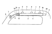
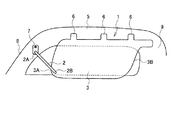
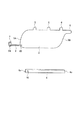
図1は本実施形態の乗員保護装置をカーテンエアバッグに適用した例であり、エアバッグ展開前の状態を示す模式図、図2は図1のカーテンエアバッグが展開した状態を示す模式図、図3は図1のカーテンエアバッグの部品図、図4は図1のカーテンエアバッグの要部を示す拡大斜視図、図5は図4のA−A線断面図、図6は折り畳んだエアバッグ本体にカバーを装着する工程図である。 FIG. 1 is an example in which the occupant protection device of the present embodiment is applied to a curtain airbag, a schematic diagram showing a state before deployment of the airbag, and FIG. 2 is a schematic diagram showing a state in which the curtain airbag of FIG. 1 is deployed, 3 is a component diagram of the curtain airbag of FIG. 1, FIG. 4 is an enlarged perspective view showing the main part of the curtain airbag of FIG. 1, FIG. 5 is a cross-sectional view taken along the line AA of FIG. It is process drawing which mounts a cover on a bag body.
カーテンエアバッグ1は、図1に示すように、テザー2が取付けられたエアバッグ本体3を折り畳んでカバー4内に収容した展開前の状態で、車両のサイドルーフレール5内に車両前後方向に沿って格納される。カーテンエアバッグ1は、サイドルーフレール5に対して複数箇所に設けた固定片部6で本体部を固定すると共に、テザー先端部に設けた固定用ブラケット7をフロントピラー8に固定させて取り付けられている。このカーテンエアバッグ1は、図2に示すように、車両側方からの衝撃等により強い衝撃を受けてフロントピラー8からリヤピラー9に亘って車室内の側面を略全体に覆うように広がって展開し、膨らんだエアバッグ本体3によって乗員頭部への衝撃を緩和する。
As shown in FIG. 1, the
エアバッグ本体3は、インフレータからエアバッグ本体3の後端部に接続した図示しない鋼管等のガス供給パイプを介して導入されるガスにより膨らんで車室内側面の略全体を覆うことのできる大きさとされている。このエアバッグ本体3には、サイドルーフレール5にエアバッグ本体3を固定するための複数の固定片部6が設けられている。なお、固定片部6の形状は、簡略化して図示している。
The airbag
テザー2は、エアバッグ本体3が膨らんで展開したときに車両前後方向に引っ張られるのを止める役目をするもので、一端側の先端部2Aを固定用ブラケット7に固定すると共に他端側の基端部2Bをエアバッグ本体3の一端側(車両前方側)に固定させている。本実施形態では、エアバッグ本体3のバッグ本体一端側にのみテザー2を設けているが、車両構成によってはエアバッグ本体3のバッグ本体他端側にもテザー2が設けられる場合もある。
The
カバー4は、折り畳まれたエアバッグ本体3を内部に収容させる細長い筒状とされている。このカバー4の長さは、例えば車両前方となる一端縁4a及び車両後方となる他端縁4bからそれぞれエアバッグ本体3の一部がカバー外へ突出する程度の長さとなっている。もちろん、このカバー4の長さは、一例であり、この実施形態に限定されるものではない。また、カバー4は、エアバッグ本体3が膨らんで展開する際に展開時の圧力で破れるように、例えば不織布から形成されている。
The
そして、特に本実施形態では、前記カバー4には、テザー2を挿通させて折返し部を形成し弛みを無くすテザー長さ調整孔10が形成されている。テザー長さ調整孔10は、少なくともテザー2の幅寸法よりも大きい開口幅に形成されている。また、このテザー長さ調整孔10は、例えばカバー4の一端縁4aからの10mm〜20mm程度の位置に設けられており、該一端縁4aに近い位置に形成されている。そして、このテザー長さ調整孔10には、図4及び図5に示すように、テザー2が挿通されている。
In particular, in the present embodiment, the
具体的には、テザー2は、エアバッグ本体3の長手方向(図4矢印X方向)にバッグ本体一端側からバッグ本体他端側へ沿わせた後、テザー先端をカバー4に形成したテザー長さ調整孔10からカバー外へ引き出して再びバッグ本体一端側へと折り返して折返し部11を形成している。この折返し部11を形成することで、テザー2の弛みを無くと共にテザー必要長さを調整することができる。
Specifically, the
折り畳んだエアバッグ本体3にカバー4を取り付けるには、先ず図6(A)に示すように、カバー4の長さが短くなるように不織布をたぐった後、カバー他端側からテザー2の先端に固定した固定用ブラケット7をその内部に挿入させる。そして、図6(B)に示すように、前記固定用ブラケット7をカバー4に形成したテザー長さ調整孔10からカバー4外に引き出す。その後、たぐったカバー4を元の状態に延ばしてエアバッグ本体3をカバー4内に収容させる。その結果、テザー2の他端側に折返し部11が形成される。折返し部11の長さを調整するには、カバー4をエアバッグ本体3に対してその装着位置をずらすようにする。
In order to attach the
このように構成されたカーテンエアバッグ1においては、図1及び図2に示したように、エアバッグ展開前の状態においてエアバッグ本体3の先端部3Aとテザー2の車体固定点(固定用ブラケット7の固定位置)までの距離が展開後のテザー2の長さよりも短い場合でも、フロントピラー8に沿って配索されるテザー2を弛ませることなく収容保持することができる。また、エアバッグ本体3の展開時には、その展開圧力でカバー4の一端縁4aからテザー長さ調整孔10までの前記カバー部分が破けて折返し部11が解けるので、展開時に前記テザー2の折返し部11が邪魔になることがない。
In the
また、本実施形態のカーテンエアバッグ1によれば、テザー長さ調整孔10からカバー4の外にテザー2を引き出すため、テザー2のエアバッグ本体3に対する周方向での位置を正確に決めることができる。つまり、テザー2の折返し部11の位置がずれることなく当該テザー2を位置決めすることができる。
Further, according to the
また、本実施形態のカーテンエアバッグ1によれば、テザー長さ調整孔10をカバー4の周方向に自由に設定して設けることができるため、車両室内側の出したい箇所からテザー2を引き出すことができる。これにより、車両構造に合わせたテザー2の取り出し位置を自由に決定できる。
Further, according to the
また、本実施形態のカーテンエアバッグ1によれば、テザー2の先端をカバー4に形成したテザー長さ調整孔10からカバー4外へ引き出して折返し部11を形成したので、このテザー長さ調整孔10によりテザー2の折返し部11を確実に形成することができる。
Further, according to the
さらに、本実施形態のカーテンエアバッグ1によれば、カバー4をエアバッグ本体3に対して車両後方へ動かすことで、簡単にテザー2の折返し部11の長さを調整することができる。
Furthermore, according to the
「第2実施形態」
図7は第2実施形態を示し、エアバッグ本体が展開したときに破断する破断容易部をテザーの折返し部と対応するカバー部分に形成した例を示す。
“Second Embodiment”
FIG. 7 shows a second embodiment, and shows an example in which an easily breakable portion that breaks when the airbag body is deployed is formed in a cover portion that corresponds to the folded portion of the tether.
第2実施形態のカーテンエアバッグ1では、図7に示すように、少なくともテザー2の折返し部11と対応するカバー4に、エアバッグ本体3が展開したときに破断する破断容易部12を形成している。破断容易部12は、例えば小さな長孔13を所定間隔でカバー4の一端縁4aから他端縁4bに掛けてテザー長さ調整孔10が形成される位置と同一線上にいわゆるミシン目となるように複数形成することで構成されている。
In the
本実施形態のカーテンエアバッグ1によれば、エアバッグ本体3が展開したときに破断する破断容易部12をカバー4に形成したので、エアバッグ展開時に破断容易部12からカバー4がより一層破け易くなり、前記テザー2の折返し部11の折返しがスムーズに解かれることになる。そのため、カバー4の一端縁4aからテザー長さ調整孔10までの距離を長くして、前記テザー2の折返し部11の長さ調整に余裕を持たせることが可能となる。
According to the
「第3実施形態」
図8は第3実施形態を示し、テザーの折返し部の別形態を示す図である。
“Third Embodiment”
FIG. 8 shows the third embodiment, and is a diagram showing another embodiment of the folded portion of the tether.
第3実施形態のカーテンエアバッグ1では、エアバッグ本体3に取付けられたテザー2の基端側を少なくとも二つ折りに折り返して形成した折返し部11の先端11Aを、カバー4に形成したテザー長さ調整孔10からカバー4外へ引き出すことで、テザー2の弛みを無くしてテザー長さ調整を実現させている。
In the
本実施形態では、テザー2の折返し部11は、その先端11Aのみがテザー長さ調整孔10からカバー4外へ引き出されている。折返し部11は、カバー4の一端縁4aとテザー長さ調整孔10との間に形成された部位14で前記エアバッグ本体3とによって押さ付けられており、容易に引き抜かれないようにされている。
In the present embodiment, only the
また、本実施形態では、テザー長さ調整孔10からカバー4外へ引出したテザー先端位置を決めるためのマーキング15Aが、例えば帯状マークとして印されている。このマーキング15Aに合わせて折返し部11の先端11Aを位置合わせすれば、どの位置まで折返し部11をテザー長さ調整孔10から引き出せば良いか目視により判断することができ、組付作業性を高めることができる。
Further, in the present embodiment, the marking 15A for determining the position of the tether leading end pulled out from the
また、カバー4には、テザー2の折返し部11をテザー長さ調整孔10から引き出す方向を示すためのマーキング15Bが、例えば矢印マークとして印されている。このため、作業者は、テザー2の折返し部11の引出し方向を間違うことが無くなる。
The
また、本実施形態では、折り畳まれたエアバッグ本体3とカバー4との装着位置(相対位置)を決める位置決めマーキング16が、当該エアバッグ本体3に例えば三角形マークとして印されている。この位置決めマーキング16に合わせてカバー4の一端縁4aの位置を決めれば、エアバッグ本体3の端部(テザー2のエアバッグ本体3に対する取り付け部位となる基端部2B)からカバー4に印したマーキング15Aまでの距離が予め決められた長さとなるため、結果としてテザー2の折返し部11の長さを所定長さとすることができる。これにより、テザー2の弛み長さが予め決められた長さとできたか否かの適否(合否)判断を簡単に行うことができ、目視により簡単にテザー2の弛み長さ調整作業を行うことができる。
In the present embodiment, the positioning marking 16 that determines the mounting position (relative position) between the folded
「第4実施形態」
図9は第4実施形態を示し、車両のエンジンフードとフロントシールドガラスとの付け根近傍部に乗員保護装置であるエアバッグを配置した例を示す図である。図9(A)では、車両中心から片側をエアバッグ展開前状態、もう片側をエアバッグ展開後状態で表している。図9(B)では、エアバッグ展開状態の車両縦断面を示している。
“Fourth Embodiment”
FIG. 9 shows the fourth embodiment and is an example in which an airbag as an occupant protection device is disposed in the vicinity of the base between the engine hood and the front shield glass of the vehicle. In FIG. 9A, one side from the vehicle center is shown in a state before the airbag is deployed, and the other side is shown in a state after the airbag is deployed. FIG. 9B shows a vehicle longitudinal section in the airbag deployed state.
第4実施形態では、エンジンフード17とフロントシールドガラス18との付け根近傍部に、本発明を適用したエアバッグ19を配置し、車両への衝突時にエアバッグ本体3を展開させて車両に衝突する人を膨らんだエアバッグ本体3で保護するように構成している。
In the fourth embodiment, an
第1実施形態では、車両室内にエアバッグ(カーテンエアバッグ1)を設けて乗員を保護するようにしたが、第4実施形態のように車両外にエアバッグ19を設けて車両に衝突する人を保護するようにした場合でも、本発明構成を適用することができる。本実施形態のエアバッグ19では、第1実施形態と同様、展開前状態の余ったテザー2を、カバー4に形成したテザー長さ調整孔10を挿通させて折返し部11を形成し弛みを無くすようにする。
In the first embodiment, the airbag (curtain airbag 1) is provided in the vehicle compartment to protect the occupant. However, as in the fourth embodiment, the
以上、本発明を適用した具体的な実施形態について説明したが、本発明は、上述した実施形態に制限されることはない。 Although specific embodiments to which the present invention is applied have been described above, the present invention is not limited to the above-described embodiments.
1…カーテンエアバッグ(乗員保護装置)
2…テザー
3…エアバッグ本体
4…カバー
10…テザー長さ調整孔
11…テザーの折返し部
12…破断容易部
15A、15B、16…マーキング
17…エンジンフード
18…フロントシールドガラス
1 ... Curtain airbag (occupant protection device)
2 ...
Claims (6)
前記エアバッグ本体を折り畳んだ状態で内部に収容させるカバーとを備え、
前記カバーに、前記テザーを挿通させて折返し部を形成し弛みを無くすテザー長さ調整孔を設けた
ことを特徴とする乗員保護装置。 An airbag body with a tether attached thereto;
A cover for accommodating the airbag main body in a folded state;
An occupant protection device, wherein the cover is provided with a tether length adjustment hole that allows the tether to be inserted to form a folded portion to eliminate slack.
前記エアバッグ本体に取付けられたテザーの基端側を折り畳まれたエアバッグ本体の長手方向にバッグ本体一端側からバッグ本体他端側へ沿わせた後、該テザーの先端を前記カバーに形成したテザー長さ調整孔からカバー外へ引き出して折返し部を形成し、エアバッグ展開時に該カバーの一端縁から該テザー長さ調整孔までの前記カバー部分が破けて前記折返し部が解ける
ことを特徴とする乗員保護装置。 The occupant protection device according to claim 1,
The base end side of the tether attached to the airbag body is folded from the bag body one end side to the bag body other end side in the longitudinal direction of the folded airbag body, and then the tip of the tether is formed on the cover. It is drawn out of the cover from the tether length adjustment hole to form a folded portion, and when the airbag is deployed, the cover portion from one edge of the cover to the tether length adjustment hole is torn and the folded portion is unwound. Occupant protection device.
前記エアバッグ本体に取付けられたテザーの基端側を少なくとも二つ折りに折り返して形成した折返し部の先端を、前記カバーに形成したテザー長さ調整孔からカバー外へ引き出した
ことを特徴とする乗員保護装置。 The occupant protection device according to claim 1,
An occupant characterized in that a tip of a folded portion formed by folding at least a base end side of a tether attached to the airbag body is pulled out of a cover from a tether length adjustment hole formed in the cover. Protective device.
少なくとも前記テザーの折返し部と対応する前記カバーには、前記エアバッグ本体が展開したときに破断する破断容易部が形成されている
ことを特徴とする乗員保護装置。 The occupant protection device according to any one of claims 1 to 3,
At least the cover corresponding to the folded portion of the tether is formed with an easily breakable portion that is broken when the airbag body is deployed.
前記カバーに、前記テザー長さ調整孔からカバー外へ引出したテザー先端位置を決めるマーキングを設けた
ことを特徴とする乗員保護装置。 The occupant protection device according to claim 3,
The occupant protection device according to claim 1, wherein the cover is provided with a marking for determining a position of a tether tip that is pulled out of the cover from the tether length adjustment hole.
前記エアバッグ本体に、前記カバーと前記エアバッグ本体との相対位置を決めるマーキングを設けた
ことを特徴とする乗員保護装置。 The occupant protection device according to any one of claims 1 to 5,
An occupant protection device, wherein the airbag body is provided with markings for determining a relative position between the cover and the airbag body.
Priority Applications (1)
| Application Number | Priority Date | Filing Date | Title |
|---|---|---|---|
| JP2007334029A JP2009154656A (en) | 2007-12-26 | 2007-12-26 | Occupant crash protection device |
Applications Claiming Priority (1)
| Application Number | Priority Date | Filing Date | Title |
|---|---|---|---|
| JP2007334029A JP2009154656A (en) | 2007-12-26 | 2007-12-26 | Occupant crash protection device |
Publications (1)
| Publication Number | Publication Date |
|---|---|
| JP2009154656A true JP2009154656A (en) | 2009-07-16 |
Family
ID=40959146
Family Applications (1)
| Application Number | Title | Priority Date | Filing Date |
|---|---|---|---|
| JP2007334029A Pending JP2009154656A (en) | 2007-12-26 | 2007-12-26 | Occupant crash protection device |
Country Status (1)
| Country | Link |
|---|---|
| JP (1) | JP2009154656A (en) |
Cited By (2)
| Publication number | Priority date | Publication date | Assignee | Title |
|---|---|---|---|---|
| US9371053B2 (en) | 2014-09-12 | 2016-06-21 | Toyota Motor Engineering & Manufacturing North America, Inc. | Package confirmation quality check tool for an airbag system and method of operation thereof |
| JP2017105391A (en) * | 2015-12-11 | 2017-06-15 | オートリブ ディベロップメント エービー | Curtain airbag device |
-
2007
- 2007-12-26 JP JP2007334029A patent/JP2009154656A/en active Pending
Cited By (2)
| Publication number | Priority date | Publication date | Assignee | Title |
|---|---|---|---|---|
| US9371053B2 (en) | 2014-09-12 | 2016-06-21 | Toyota Motor Engineering & Manufacturing North America, Inc. | Package confirmation quality check tool for an airbag system and method of operation thereof |
| JP2017105391A (en) * | 2015-12-11 | 2017-06-15 | オートリブ ディベロップメント エービー | Curtain airbag device |
Similar Documents
| Publication | Publication Date | Title |
|---|---|---|
| WO2011037199A1 (en) | Curtain airbag device | |
| JP5582751B2 (en) | Curtain airbag device | |
| US7854448B2 (en) | Airbag arrangement | |
| JP5401288B2 (en) | Curtain airbag device | |
| JP2006069248A (en) | Curtain airbag device | |
| JP2007153223A (en) | Airbag device for vehicle | |
| JP2009292441A (en) | Curtain airbag bracket and curtain airbag apparatus | |
| US8430423B2 (en) | Interior structure of vehicle | |
| JP2014234099A (en) | Curtain airbag and curtain airbag device | |
| JP5574656B2 (en) | Curtain airbag device | |
| JP2009154656A (en) | Occupant crash protection device | |
| JP2008114739A (en) | Vehicle rear structure provided with curtain airbag device | |
| JP5015851B2 (en) | Vehicle occupant protection device | |
| JP2010083240A (en) | Air-bag and airbag device | |
| JP5815789B2 (en) | Curtain airbag device | |
| JP2011168106A (en) | Gas straightening device | |
| JP2010195329A (en) | Protector for air-bag and air-bag device using protector | |
| JP5318616B2 (en) | Curtain airbag device | |
| JP5714746B2 (en) | Curtain airbag device | |
| JP2009166794A (en) | Airbag device | |
| JP4069791B2 (en) | Head protection airbag device | |
| JP5793128B2 (en) | Airbag device | |
| JP2005271703A (en) | Airbag device for knee protection | |
| JP2011168107A (en) | Gas straightening device | |
| JP2006213113A (en) | Head part protecting airbag device |