JP2009143753A - Bonding material for SiC honeycomb and honeycomb structure - Google Patents
Bonding material for SiC honeycomb and honeycomb structure Download PDFInfo
- Publication number
- JP2009143753A JP2009143753A JP2007321143A JP2007321143A JP2009143753A JP 2009143753 A JP2009143753 A JP 2009143753A JP 2007321143 A JP2007321143 A JP 2007321143A JP 2007321143 A JP2007321143 A JP 2007321143A JP 2009143753 A JP2009143753 A JP 2009143753A
- Authority
- JP
- Japan
- Prior art keywords
- honeycomb
- bonding material
- sic
- honeycomb structure
- binder
- Prior art date
- Legal status (The legal status is an assumption and is not a legal conclusion. Google has not performed a legal analysis and makes no representation as to the accuracy of the status listed.)
- Pending
Links
Images


Landscapes
- Ceramic Products (AREA)
- Catalysts (AREA)
- Processes For Solid Components From Exhaust (AREA)
- Filtering Materials (AREA)
- Filtering Of Dispersed Particles In Gases (AREA)
Abstract
【課題】耐熱性に優れたハニカム構造体を提供すること。
【解決手段】本発明のハニカム構造体1は、多孔質のSiCセラミックスよりなるハニカム分体2と、二つのハニカム分体2の間に位置し、ハニカム分体2を接合するSiCハニカム用接合材層5と、を有するハニカム構造体1であって、SiCハニカム用接合材層5は、平均粒径(D50)が5μm以下のSiCよりなる微細粉末と、平均粒径(D50)が5〜100μmのSiCよりなる粗大粉末と、繊維長が10μm〜1mmの無機繊維と、各粉末および無機繊維が分散した分散媒と、有機バインダおよび/または無機バインダよりなるバインダと、を有する接合材より形成されたことを特徴とする。
【選択図】図4A honeycomb structure having excellent heat resistance is provided.
A honeycomb structure 1 according to the present invention includes a honeycomb split body 2 made of porous SiC ceramics and a bonding material for SiC honeycomb that is positioned between two honeycomb split bodies 2 and joins the honeycomb split bodies 2. The bonding material layer 5 for SiC honeycomb has a fine powder made of SiC having an average particle size (D50) of 5 μm or less, and an average particle size (D50) of 5 to 100 μm. Formed of a bonding material having a coarse powder made of SiC, an inorganic fiber having a fiber length of 10 μm to 1 mm, a dispersion medium in which each powder and inorganic fiber are dispersed, and a binder made of an organic binder and / or an inorganic binder. It is characterized by that.
[Selection] Figure 4
Description
本発明は、SiCセラミックスよりなるハニカム分体を接合する接合材及びハニカム構造体に関する。 The present invention relates to a bonding material and a honeycomb structure for bonding honeycomb bodies made of SiC ceramics.
内燃機関、ボイラー、化学反応機器、燃料電池用改質器等の触媒作用を利用する触媒用担体、排ガス中のスス等の微粒子(特にディーゼルエンジンからの排気ガス中の微粒子物質(PM))の捕集フィルタ(以下、DPFという)等には、セラミックス製のハニカム構造体が用いられている。 Catalytic carrier utilizing catalytic action of internal combustion engine, boiler, chemical reaction equipment, fuel cell reformer, etc., particulates such as soot in exhaust gas (particularly particulate matter (PM) in exhaust gas from diesel engine) A ceramic honeycomb structure is used for a collection filter (hereinafter referred to as DPF).
SiCセラミックス製のハニカム構造体よりなるDPFは、隔壁部のセルを区画する隔壁を排気ガスが通過するウォールフロー型のフィルタとして用いられている。ウォールフロー型のフィルタは、セル壁に形成された連続した細孔を排気ガスが通過し、細孔を通過できない排気ガス中のPMを捕集する。 A DPF comprising a honeycomb structure made of SiC ceramics is used as a wall flow type filter through which exhaust gas passes through partition walls that partition partition wall cells. A wall flow type filter collects PM in exhaust gas through which exhaust gas passes through continuous pores formed in a cell wall and cannot pass through the pores.
DPFは、捕集したPMが堆積したままでは目詰まりを起こすため、捕集したPMを除去する必要がある。捕集したPMを除去する方法のひとつに燃焼等によりPMを分解・除去する方法がある。また、DPFは、触媒活性を発揮する触媒金属を担持し、この触媒金属でPMを分解する方法もある。 Since the DPF is clogged when the collected PM is accumulated, it is necessary to remove the collected PM. One method of removing the collected PM is a method of decomposing and removing PM by combustion or the like. There is also a method in which DPF supports a catalytic metal that exhibits catalytic activity and decomposes PM with this catalytic metal.
燃焼によりPMを除去するときには、ハニカム構造体が加熱される。そして、加熱による急激な温度変化により、ハニカム構造体を構成するセラミックスに体積変化(熱膨張)が生じる。この結果、ハニカム構造体に熱膨張による応力が発生し、より高い温度に加熱されると、応力が集中してヒビや割れが生じるという問題が発生していた。 When removing PM by combustion, the honeycomb structure is heated. A sudden temperature change due to heating causes a volume change (thermal expansion) in the ceramics constituting the honeycomb structure. As a result, a stress due to thermal expansion is generated in the honeycomb structure, and when the honeycomb structure is heated to a higher temperature, the stress is concentrated and cracks and cracks are generated.
この熱膨張による破壊の問題を解決するためにハニカム構造体はいくつかのセグメントに分割されたハニカム分体を接合材で接合して形成されているが、ハニカム分体を接合材で接合してなるハニカム構造体において、接合材の熱膨張率が大きい場合や接合材が非常に固い構造を有する場合には、接合材層がハニカム分体の体積変化を吸収できず、ハニカム分体が破壊される、もしくは接合材層が破壊され、ハニカム分体が剥離するおそれがあった。 In order to solve the problem of destruction due to thermal expansion, a honeycomb structure is formed by joining honeycomb segments divided into several segments with a bonding material. When the bonding material has a large thermal expansion coefficient or the bonding material has a very hard structure, the bonding material layer cannot absorb the volume change of the honeycomb body, and the honeycomb body is destroyed. Otherwise, the bonding material layer may be destroyed, and the honeycomb body may be peeled off.
本発明は上記実状に鑑みてなされたものであり、より高い温度に晒されても損傷を生じないハニカム構造体を得られる接合材を提供することを課題とする。 This invention is made | formed in view of the said actual condition, and makes it a subject to provide the joining material which can obtain the honeycomb structure which does not produce a damage even if it exposes to higher temperature.
上記課題を解決するために本発明者は、ハニカム分体を接合する接合材であって、ハニカム分体の体積変化を吸収できる接合材について検討を重ねた結果本発明をなすに至った。 In order to solve the above-mentioned problems, the present inventor has made the present invention as a result of repeated studies on a bonding material for bonding honeycomb bodies, which can absorb the volume change of the honeycomb bodies.
すなわち、本発明のSiCハニカム用接合材は、多孔質のSiCセラミックスよりなるハニカム分体を接合してハニカム構造体とするSiCハニカム用接合材であって、SiCハニカム用接合材は、平均粒径(D50)が5μm以下のSiCよりなる微細粉末と、平均粒径(D50)が5〜100μmのSiCよりなる粗大粉末と、繊維長が10μm〜1mmの無機繊維と、各粉末および無機繊維が分散した分散媒と、有機バインダおよび/または無機バインダよりなるバインダと、を有することを特徴とする。 That is, the SiC honeycomb bonding material of the present invention is a SiC honeycomb bonding material in which a honeycomb body made of porous SiC ceramics is bonded to form a honeycomb structure, and the SiC honeycomb bonding material has an average particle diameter. Fine powder made of SiC having (D50) of 5 μm or less, coarse powder made of SiC having an average particle diameter (D50) of 5 to 100 μm, inorganic fibers having a fiber length of 10 μm to 1 mm, and each powder and inorganic fiber dispersed And a binder composed of an organic binder and / or an inorganic binder.
また、本発明のハニカム構造体は、多孔質のSiCセラミックスよりなるハニカム分体と、二つのハニカム分体の間に位置し、ハニカム分体を接合するSiCハニカム用接合材層と、を有するハニカム構造体であって、SiCハニカム用接合材層は、平均粒径(D50)が5μm以下のSiCよりなる微細粉末と、平均粒径(D50)が5〜100μmのSiCよりなる粗大粉末と、繊維長が10μm〜1mmの無機繊維と、各粉末および無機繊維が分散した分散媒と、有機バインダおよび/または無機バインダよりなるバインダと、を有する接合材より形成されたことを特徴とする。 The honeycomb structure of the present invention includes a honeycomb body made of porous SiC ceramics, and a bonding member layer for SiC honeycomb that is positioned between the two honeycomb bodies and joins the honeycomb bodies. The SiC honeycomb bonding material layer includes a fine powder made of SiC having an average particle diameter (D50) of 5 μm or less, a coarse powder made of SiC having an average particle diameter (D50) of 5 to 100 μm, fibers It is formed from a bonding material having an inorganic fiber having a length of 10 μm to 1 mm, a dispersion medium in which each powder and inorganic fiber are dispersed, and a binder made of an organic binder and / or an inorganic binder.
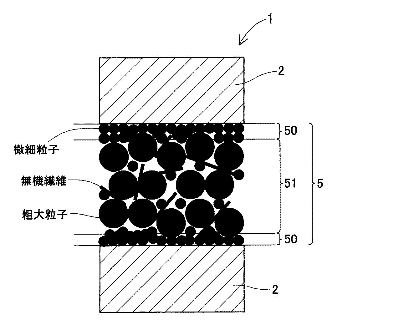
本発明のSiCハニカム用接合材は、ハニカム分体を接合したときに形成される接合材層が、多孔質の中間層部を有することとなる。すなわち、接合材層は、この中間層部に多数の細孔(空間)が形成される。この中間層に形成された空間が、ハニカム分体の熱膨張などによる体積変化を吸収する。これにより、ハニカム分体が熱膨張を生じても、ハニカム構造体の損傷が抑えられる。この結果、本発明の接合材を用いてハニカム分体を接合したハニカム構造体は、高い耐熱性を発揮する。 In the bonding material for SiC honeycomb of the present invention, the bonding material layer formed when the honeycomb segments are bonded has a porous intermediate layer portion. That is, the bonding material layer has a large number of pores (spaces) formed in the intermediate layer portion. The space formed in the intermediate layer absorbs the volume change due to the thermal expansion of the honeycomb body. Thereby, even if the honeycomb segment causes thermal expansion, damage to the honeycomb structure can be suppressed. As a result, the honeycomb structure in which the honeycomb segments are bonded using the bonding material of the present invention exhibits high heat resistance.
本発明のハニカム構造体は、ハニカム分体を接合している接合材層が多数の細孔をもつ中間層を有するものとなっている。この中間層の細孔により形成された空間が、ハニカム分体の体積変化を吸収する。これにより、ハニカム構造体の損傷が抑えられる。この結果、本発明のハニカム構造体は、高い耐熱性を発揮する。 In the honeycomb structure of the present invention, the bonding material layer for bonding the honeycomb segments has an intermediate layer having a large number of pores. The space formed by the pores of the intermediate layer absorbs the volume change of the honeycomb body. Thereby, damage to the honeycomb structure is suppressed. As a result, the honeycomb structure of the present invention exhibits high heat resistance.
(SiCハニカム用接合材)
本発明のSiCハニカム用接合材は、多孔質のSiCセラミックスよりなるハニカム分体を接合してハニカム構造体とするSiCハニカム用接合材である。つまり、本発明の接合材は、多孔質のSiCセラミックスよりなるハニカム分体を接合してハニカム構造体を形成するときに、ハニカム分体を接合するために用いられる接合材である。
(Bonding material for SiC honeycomb)
The bonding material for SiC honeycomb of the present invention is a bonding material for SiC honeycomb in which a honeycomb structure made of porous SiC ceramics is bonded to form a honeycomb structure. That is, the bonding material of the present invention is a bonding material used for bonding a honeycomb body when a honeycomb body made of porous SiC ceramics is bonded to form a honeycomb structure.
そして、本発明の接合材は、平均粒径(D50)が5μm以下のSiCよりなる微細粉末と、平均粒径(D50)が5〜100μmのSiCよりなる粗大粉末と、繊維長が10μm〜1mmの無機繊維と、各粉末および無機繊維が分散した分散媒と、有機バインダおよび/または無機バインダよりなるバインダと、を有する。 The bonding material of the present invention has a fine powder made of SiC having an average particle diameter (D50) of 5 μm or less, a coarse powder made of SiC having an average particle diameter (D50) of 5 to 100 μm, and a fiber length of 10 μm to 1 mm. Inorganic fibers, a dispersion medium in which each powder and inorganic fibers are dispersed, and a binder made of an organic binder and / or an inorganic binder.
本発明の接合材をハニカム分体の接合のために、ハニカム分体の表面に塗布して別のハニカム分体を重ね合わせると、ハニカム分体が多孔質のセラミックスよりなることから、毛細管現象により分散媒の一部(特に、ハニカム分体の表面近傍に位置する分散媒の一部)がハニカム分体の細孔内に侵入することとなり、分散媒がハニカム分体に吸収される。この分散媒の吸収(移動)に伴って、微細粉末もハニカム分体に向かって移動する。そして、微細粉末がハニカム分体の表面側に多く存在するようになる。このとき、粗大粉末および無機繊維は、移動しない(あるいは移動量がごくわずか)ため、それぞれの粒子の位置が保持される。そして、この状態で、接合材を構成する粗大粉末および無機繊維が固定され、二つのハニカム分体を接合する接合材層が形成される。 When the bonding material of the present invention is applied to the surface of the honeycomb body and bonded with another honeycomb body to join the honeycomb body, the honeycomb body is made of porous ceramics. Part of the dispersion medium (particularly, part of the dispersion medium located near the surface of the honeycomb body) enters the pores of the honeycomb body, and the dispersion medium is absorbed by the honeycomb body. As the dispersion medium is absorbed (moved), the fine powder also moves toward the honeycomb body. A large amount of fine powder is present on the surface side of the honeycomb body. At this time, since the coarse powder and the inorganic fiber do not move (or the movement amount is very small), the position of each particle is maintained. In this state, the coarse powder and the inorganic fibers constituting the bonding material are fixed, and a bonding material layer for bonding the two honeycomb segments is formed.
本発明の接合材でハニカム分体を接合して形成される接合材層の断面を観察すると、ハニカム分体の表面近傍側には微細粉末が大きな割合で含まれる(ほぼ微細粉末よりなる)表層部と、表層部の間に粗大粉末と無機繊維が多く含まれる(ほぼ粗大粉末と無機繊維とからなる)中間層部と、が確認できるようになる。 When the cross section of the bonding material layer formed by bonding the honeycomb bodies with the bonding material of the present invention is observed, a surface layer in which the fine powder is contained in a large proportion (substantially composed of the fine powder) on the surface side of the honeycomb body. Part and the intermediate layer part containing a large amount of coarse powder and inorganic fibers (substantially consisting of coarse powder and inorganic fibers) can be confirmed between the surface part and the surface layer part.
このように、本発明の接合材を用いてハニカム分体を接合すると、ハニカム分体との当接部を形成する表層部と、表層部の内部に位置する多孔質の中間層部と、を有する接合材層が形成される。つまり、ハニカム構造体を形成したときに接合材よりなる接合材層がすき間を有する構成となっている。このすき間が、ハニカム分体の体積変化を緩衝することとなり、ハニカム構造体の耐熱性が向上する。 As described above, when the honeycomb body is bonded using the bonding material of the present invention, a surface layer portion that forms a contact portion with the honeycomb body, and a porous intermediate layer portion positioned inside the surface layer portion, A bonding material layer is formed. That is, the bonding material layer made of the bonding material has a gap when the honeycomb structure is formed. This gap buffers the volume change of the honeycomb body, and the heat resistance of the honeycomb structure is improved.
また、表層部は、ハニカム分体を接合したときに、ハニカム分体との当接部を形成する。この表層部は、ほぼ微細粉末よりなるため、充填密度が高くなり、中間層部のようなすき間がほとんど存在しない。すき間が存在しないことから、ハニカム分体との当接面にすき間による細孔が存在せず、接合材層とハニカム分体の当接面積が確保される。 Further, the surface layer portion forms a contact portion with the honeycomb body when the honeycomb body is joined. Since the surface layer portion is substantially made of fine powder, the packing density is increased, and there are almost no gaps as in the intermediate layer portion. Since there is no gap, pores due to the gap do not exist on the contact surface with the honeycomb body, and the contact area between the bonding material layer and the honeycomb body is ensured.
本発明の接合材は、接合された二つのハニカム分体の間で接合材層を形成する。そして、接合材層は、ハニカム分体が積層した厚さ方向で、表層部、中間層部、表層部の順序で表層部及び中間層部を有する。このとき、中間層部は、すき間を確保しつつ二つの表層部を固定している。 The bonding material of the present invention forms a bonding material layer between two bonded honeycomb bodies. The bonding material layer has a surface layer portion and an intermediate layer portion in the order of the surface layer portion, the intermediate layer portion, and the surface layer portion in the thickness direction in which the honeycomb bodies are laminated. At this time, the intermediate layer portion fixes the two surface layer portions while ensuring a gap.
中間層部のすき間は、中間層部に均一に分散した細孔よりなることが好ましい。このとき、中間層部に形成された細孔の細孔径や気孔率などは、接合されるハニカム分体により異なる。 The gap in the intermediate layer portion is preferably composed of pores uniformly dispersed in the intermediate layer portion. At this time, the pore diameter, the porosity, etc. of the pores formed in the intermediate layer portion differ depending on the bonded honeycomb bodies.
接合材を構成する粗大粉末は、D50が5μmを超え、100μm以下である。粗大粉末のD50が、5μm以下となると、粒径が小さくなり、中間層部にすき間ができなくなり、ハニカム構造体を形成したときにハニカム分体の熱膨張による伸びを吸収できなくなる。また、粗大粉末のD50が100μmを超えると、粒径が大きくなりすぎて粗大粉末が沈降するなど、接合材でハニカム分体を接合するときの取り扱いが困難となるだけでなく、形成される接合材層の強度低下を招くようになる。 The coarse powder constituting the bonding material has a D50 of more than 5 μm and 100 μm or less. When the D50 of the coarse powder is 5 μm or less, the particle size becomes small, and there is no gap in the intermediate layer portion, and when the honeycomb structure is formed, the elongation due to the thermal expansion of the honeycomb body cannot be absorbed. In addition, when the D50 of the coarse powder exceeds 100 μm, the particle size becomes too large and the coarse powder settles, so that not only the handling when joining the honeycomb body with the joining material becomes difficult, but also the formed joint The strength of the material layer is reduced.
本発明の接合材において、粗大粉末の含有割合については特に限定されるものではない。本発明の接合材において、接合材全体の重量を100wt%としたときに、20〜50wt%で粗大粉末が含まれることが好ましい。粗大粉末の割合がこの範囲内となることで、粗大粉末を含有する効果が発揮される。粗大粉末が20wt%未満では、粗大粉末の割合が低すぎ、中間層部に十分なすき間が形成できなくなる(十分な気孔率が得られなくなる)。粗大粉末が50wt%を超えると、大きなすき間が形成され、接合材層の強度が低下する。 In the bonding material of the present invention, the content ratio of the coarse powder is not particularly limited. In the bonding material of the present invention, it is preferable that coarse powder is contained at 20 to 50 wt% when the weight of the entire bonding material is 100 wt%. When the ratio of the coarse powder is within this range, the effect of containing the coarse powder is exhibited. If the coarse powder is less than 20 wt%, the proportion of the coarse powder is too low, and a sufficient gap cannot be formed in the intermediate layer portion (sufficient porosity cannot be obtained). When the coarse powder exceeds 50 wt%, a large gap is formed and the strength of the bonding material layer is lowered.
また、接合材を構成する微細粉末は、D50が5μm以下である。微細粉末のD50が5μm以上となると、ハニカム分体の表面に塗布されたときに微細粉末がハニカム分体側に移動しにくくなり、接合材層が表層部と中間層部を形成できなくなる。また、接合材層の接合力が低下する。また、粗大粉末との粒径差が小さくなり、粗大粉末と微細粉末とを混在させる効果が十分に得られなくなる。微細粉末のD50は、3μm以下であることより好ましい。 The fine powder constituting the bonding material has a D50 of 5 μm or less. When the D50 of the fine powder is 5 μm or more, the fine powder is difficult to move to the honeycomb divided side when applied to the surface of the honeycomb divided body, and the bonding material layer cannot form the surface layer portion and the intermediate layer portion. Further, the bonding strength of the bonding material layer is reduced. Further, the particle size difference from the coarse powder becomes small, and the effect of mixing the coarse powder and the fine powder cannot be obtained sufficiently. The D50 of the fine powder is more preferably 3 μm or less.
本発明の接合材において、微細粉末の含有割合については特に限定されるものではない。本発明の接合材において、接合材全体の重量を100wt%としたときに、15〜40wt%で微細粉末が含まれることが好ましい。微細粉末の割合がこの範囲内となることで、微細粉末を含有する効果が発揮される。微細粉末が15wt%未満では、微細粉末の割合が低すぎ、表層部が形成できなくなる。微細粉末が40wt%を超えると、表層部の厚さが過剰に厚くなるとともに、表層部に十分なすき間が形成できなくなる。 In the bonding material of the present invention, the content ratio of the fine powder is not particularly limited. In the bonding material of the present invention, it is preferable that the fine powder is contained at 15 to 40 wt% when the weight of the entire bonding material is 100 wt%. When the proportion of the fine powder is within this range, the effect of containing the fine powder is exhibited. If the fine powder is less than 15 wt%, the proportion of the fine powder is too low to form the surface layer portion. When the fine powder exceeds 40 wt%, the thickness of the surface layer portion becomes excessively thick, and a sufficient gap cannot be formed in the surface layer portion.
ここで、微細粉末及び粗大粉末を構成するSiCは、SiCを主成分とする材料であればよく、好ましくはSiCのみからなる材料である。 Here, SiC constituting the fine powder and the coarse powder may be a material mainly composed of SiC, and is preferably a material composed of SiC only.
接合材を構成する無機繊維は、繊維長が10μm〜1mmである。無機繊維は、接合材層において、中間層部で粗大粉末を固定するとともに中間層部の補強材として機能する。無機繊維の繊維長が10μm以下では、繊維長が短すぎて、粗大粉末と形状が近似することとなり、無機繊維としての機能が果たせなくなる。また、繊維長が1mm以上となると、無機繊維が長手方向に配向し、どちらも補強材としての役割を果たせなくなる。 The inorganic fiber constituting the bonding material has a fiber length of 10 μm to 1 mm. In the bonding material layer, the inorganic fiber fixes the coarse powder in the intermediate layer portion and functions as a reinforcing material for the intermediate layer portion. When the fiber length of the inorganic fiber is 10 μm or less, the fiber length is too short and the shape of the coarse powder is approximated, and the function as the inorganic fiber cannot be performed. Further, when the fiber length is 1 mm or more, the inorganic fibers are oriented in the longitudinal direction, and neither of them can serve as a reinforcing material.
接合材を構成する無機繊維は、その材質が特に限定されるものではなく、従来公知の材質を用いることができる。無機繊維としては、たとえば、ムライト、シリカ、アルミナ、SiC等よりなる無機繊維を用いることができる。 The material of the inorganic fiber constituting the bonding material is not particularly limited, and a conventionally known material can be used. As the inorganic fiber, for example, an inorganic fiber made of mullite, silica, alumina, SiC or the like can be used.
本発明の接合材において、無機繊維の含有割合については特に限定されるものではない。本発明の接合材において、接合材全体の重量を100wt%としたときに、3〜10wt%で無機繊維が含まれることが好ましい。無機繊維の割合がこの範囲内となることで、無機繊維を含有する効果が発揮される。無機繊維が3wt%未満では、無機繊維の割合が低すぎ、添加の効果が無くなり、接合材層の強度が低下する。無機繊維が10wt%を超えると、無機繊維が過剰となり、補強材として機能しない繊維が存在するようになる。 In the bonding material of the present invention, the content ratio of the inorganic fibers is not particularly limited. In the bonding material of the present invention, it is preferable that the inorganic fiber is contained at 3 to 10 wt% when the weight of the entire bonding material is 100 wt%. When the proportion of the inorganic fiber is within this range, the effect of containing the inorganic fiber is exhibited. When the inorganic fiber is less than 3 wt%, the proportion of the inorganic fiber is too low, the effect of addition is lost, and the strength of the bonding material layer is reduced. When inorganic fiber exceeds 10 wt%, inorganic fiber will become excess and the fiber which does not function as a reinforcing material will exist.
本発明の接合材において、微細粉末,粗大粉末および無機繊維が分散する分散媒は、これらの粒子及び繊維を分散させることができる分散媒であれば特に限定されるものではない。 In the bonding material of the present invention, the dispersion medium in which the fine powder, coarse powder and inorganic fibers are dispersed is not particularly limited as long as the dispersion medium can disperse these particles and fibers.
バインダは、有機バインダおよび/または無機バインダよりなる。バインダは、微細粉末、粗大粉末及び無機繊維を均一に分散させる。バインダを有することで、粉末及び繊維が均一に分散した接合材となり、接合材を塗布した時に粉末及び繊維が均一な状態で展伸される。無機バインダは、粉末及び繊維を結合し、有機バインダは接合材の塗布性を向上させる。バインダは、無機バインダを有することがより好ましい。 The binder is made of an organic binder and / or an inorganic binder. The binder uniformly disperses fine powder, coarse powder, and inorganic fibers. By having a binder, it becomes a bonding material in which powder and fibers are uniformly dispersed, and when the bonding material is applied, the powder and fibers are spread in a uniform state. An inorganic binder combines powder and fiber, and an organic binder improves the applicability of the bonding material. More preferably, the binder has an inorganic binder.
本発明の接合材は、多孔質のSiCセラミックスよりなるハニカム分体の接合される表面に塗布され、別のハニカム分体が重ね合わせられて張り合わされた状態で、SiCの焼結温度よりも低い温度で加熱することで、ハニカム分体を接合することができる。 The bonding material of the present invention is applied to a surface to be bonded to a honeycomb segment made of porous SiC ceramics, and is lower than the sintering temperature of SiC in a state where another honeycomb segment is overlapped and bonded. By heating at a temperature, the honeycomb bodies can be joined.
本発明の接合材は、接合材全体の重量を100wt%としたときに、微細粉末が15〜40wt%、粗大粉末が20〜50wt%、無機繊維が3〜10wt%の割合でそれぞれが含まれることが好ましい。 The bonding material of the present invention includes fine powders of 15 to 40 wt%, coarse powders of 20 to 50 wt%, and inorganic fibers of 3 to 10 wt% when the total weight of the bonding material is 100 wt%. It is preferable.
(ハニカム構造体)
本発明のハニカム構造体は、多孔質のSiCセラミックスよりなるハニカム分体と、二つのハニカム分体の間に位置し、ハニカム分体を接合するSiCハニカム用接合材層と、を有するハニカム構造体である。すなわち、本発明のハニカム構造体は、従来公知のハニカム構造体のように、複数部のハニカム分体を接合材で接合した構成となっている。このような構成は、ハニカム分体ごとにその特性(細孔特性など)を変化させることができ、ハニカム構造体全体に所望の性能を付与できる。
(Honeycomb structure)
A honeycomb structure of the present invention has a honeycomb structure made of porous SiC ceramics, and a bonding material layer for SiC honeycomb that is positioned between the two honeycomb structures and joins the honeycomb structures. It is. That is, the honeycomb structure of the present invention has a configuration in which a plurality of honeycomb segments are bonded with a bonding material, as in a conventionally known honeycomb structure. Such a configuration can change the characteristics (pore characteristics, etc.) for each honeycomb body, and can give desired performance to the entire honeycomb structure.
そして、SiCハニカム用接合材層は、平均粒径(D50)が5μm以下のSiCよりなる微細粉末と、平均粒径(D50)が5〜100μmのSiCよりなる粗大粉末と、繊維長が10μm〜1mmの無機繊維と、各粉末および無機繊維が分散した分散媒と、有機バインダおよび/または無機バインダよりなるバインダと、を有する接合材より形成される。すなわち、本発明のハニカム構造体は、上記の接合材でハニカム分体を接合してなるハニカム構造体であり、耐熱性に優れたハニカム構造体である。 The bonding material layer for SiC honeycomb has a fine powder made of SiC having an average particle diameter (D50) of 5 μm or less, a coarse powder made of SiC having an average particle diameter (D50) of 5 to 100 μm, and a fiber length of 10 μm to It is formed from a bonding material having 1 mm inorganic fiber, a dispersion medium in which each powder and inorganic fiber are dispersed, and a binder made of an organic binder and / or an inorganic binder. That is, the honeycomb structure of the present invention is a honeycomb structure formed by bonding honeycomb segments with the bonding material described above, and is a honeycomb structure excellent in heat resistance.
本発明のハニカム構造体において、ハニカム分体を構成する多孔質のSiCセラミックスは、SiCを主成分として構成された多孔質のセラミックスであればよく、SiCのみからなるものだけに限定されるものではない。また、ハニカム分体を構成する多孔質のSiCセラミックスの細孔径(平均細孔径)や気孔率は、特に限定されるものではない。 In the honeycomb structure of the present invention, the porous SiC ceramics constituting the honeycomb segment may be porous ceramics composed mainly of SiC, and is not limited to those composed only of SiC. Absent. Moreover, the pore diameter (average pore diameter) and porosity of the porous SiC ceramics constituting the honeycomb body are not particularly limited.
本発明のハニカム構造体は、上記したように、ハニカム分体に塗布された接合材の水分等がハニカム分体に吸収されることで、中間層部及び表層部を備えた中間層部を形成できる。ハニカム分体の吸水性に寄与する細孔径や気孔率は、特に限定されるものではない。すなわち、ハニカム分体は、平均細孔径が2〜30μm、気孔率が20〜70%であることが好ましい。平均細孔径が5〜20μm、気孔率が30〜60%であることがより好ましい。ここで、平均細孔径や気孔率がこれらの範囲未満となると、吸水性が低下して所望の接合材層が形成できなくなり、平均細孔径や気孔率がこれらの範囲を超えると、フィルタ触媒として使用したときに所望の径のPMを捕集できなくなる。 As described above, the honeycomb structure of the present invention forms the intermediate layer portion including the intermediate layer portion and the surface layer portion by the moisture content of the bonding material applied to the honeycomb divided body being absorbed by the honeycomb divided body. it can. The pore diameter and porosity contributing to the water absorption of the honeycomb body are not particularly limited. That is, the honeycomb body preferably has an average pore diameter of 2 to 30 μm and a porosity of 20 to 70%. More preferably, the average pore diameter is 5 to 20 μm and the porosity is 30 to 60%. Here, when the average pore diameter and the porosity are less than these ranges, the water absorption decreases and a desired bonding material layer cannot be formed. When the average pore diameter and the porosity exceed these ranges, the filter catalyst When used, PM having a desired diameter cannot be collected.
ハニカム分体は、多数のセルの一方の端部または他方の端部がセラミックスよりなる封止材に封止されていることが好ましい。セルの一方の端部または他方の端部が封止材で封止されることで、ウォールフロー型のハニカム構造体を形成できる。封止材を構成するセラミックスは、その材質が特に限定されるものではなく、ハニカム分体を構成する多孔質のSiCセラミックスと同じ材質であっても、異なる材質であっても、いずれでもよい。より好ましくは、多孔質のSiCセラミックスを主成分としてなるセラミックスである。 In the honeycomb body, one end or the other end of many cells is preferably sealed with a sealing material made of ceramics. A wall flow type honeycomb structure can be formed by sealing one end or the other end of the cell with a sealing material. The material of the ceramic constituting the sealing material is not particularly limited, and may be the same material as the porous SiC ceramic constituting the honeycomb body or a different material. More preferably, the ceramic is mainly composed of porous SiC ceramics.
本発明のハニカム構造体において、セルの形状(断面形状)は、特に限定されるものではなく、従来公知の断面形状とすることができる。従来公知のセル形状のうち、正方形状であることがより好ましい。 In the honeycomb structure of the present invention, the cell shape (cross-sectional shape) is not particularly limited, and may be a conventionally known cross-sectional shape. Of the conventionally known cell shapes, a square shape is more preferable.
本発明のハニカム構造体は、ディーゼルエンジンからの排気ガス中の粒子状物質(PM)を除去するDPFに用いることが好ましい。本発明のハニカム構造体は、セルを区画する隔壁を排気ガス(気体)が通過するウォールフロー型のフィルタとして用いることができ、このようなフィルタのうち特に、DPFとして用いることが好ましい。 The honeycomb structure of the present invention is preferably used for a DPF that removes particulate matter (PM) in exhaust gas from a diesel engine. The honeycomb structure of the present invention can be used as a wall flow type filter through which exhaust gas (gas) passes through partition walls that partition cells, and among these filters, it is particularly preferable to use as a DPF.
本発明のハニカム構造体をDPFとして用いるときに、少なくとも隔壁部の細孔表面に、アルミナ等よりなる多孔質酸化物、Pt,Pd,Rh等の触媒金属の少なくともひとつを担持してもよい。これらの物質を担持したことで、DPFとしてパティキュレートなどの浄化性能が向上する。 When the honeycomb structure of the present invention is used as a DPF, at least one of a porous oxide made of alumina or the like, or a catalytic metal such as Pt, Pd, or Rh may be supported on at least the pore surfaces of the partition walls. By carrying these substances, purification performance such as particulates as DPF is improved.
本発明のハニカム構造体は、その外周形状が特に限定されるものではなく、従来公知の形状とすることができる。たとえば、断面が真円や楕円の略円柱状、断面が方形や多角形の角柱状とすることができ、より好ましくは円柱形状である。 The outer peripheral shape of the honeycomb structure of the present invention is not particularly limited, and can be a conventionally known shape. For example, the cross section may be a substantially circular or elliptical cylinder, and the cross section may be a square or polygonal prism, and more preferably a cylinder.
以下、実施例を用いて本発明を説明する。 Hereinafter, the present invention will be described using examples.
本発明の実施例として、SiCハニカム用接合材を調製し、調製された接合材を用いてハニカム構造体を製造した。 As an example of the present invention, a SiC honeycomb bonding material was prepared, and a honeycomb structure was manufactured using the prepared bonding material.
(実施例)
平均粒径(D50)が38μmのSiC粉末(粗大粉末)(信濃電気製錬株式会社製、商品名:GP#400)、D50が1.0μmのSiC粉末(微細粉末)(信濃電気製錬株式会社製、商品名:SER−A10)、繊維長が1mm以下のムライトよりなる無機繊維(新日化サーマルセラミックス株式会社製、商品名:SC1260−A10)、1.5wt%でカルボキシルメチルセルロース(CMC)を含む水溶液よりなる有機バインダ(ダイセル化学工業株式会社製、商品名:DN400H)、コロイダルシリカよりなる無機バインダ(日産化学工業株式会社製、商品名:スノーテックスO)を表1に示した割合で秤量し、混練した。これにより、本実施例のSiCハニカム用接合材が調製された。
(Example)
SiC powder (coarse powder) having an average particle size (D50) of 38 μm (trade name: GP # 400, manufactured by Shinano Denki Smelting Co., Ltd.), SiC powder (fine powder) having a D50 of 1.0 μm (Shinano Denki Smelting Co., Ltd.) Company-made, product name: SER-A10), inorganic fiber made of mullite having a fiber length of 1 mm or less (manufactured by Nikka Chemical Ceramics Co., Ltd., product name: SC1260-A10), 1.5 wt% carboxyl methyl cellulose (CMC) Table 1 shows organic binders (made by Daicel Chemical Industries, Ltd., trade name: DN400H) and inorganic binders (made by Nissan Chemical Industries, trade name: Snowtex O) made of colloidal silica. Weighed and kneaded. Thereby, the bonding material for SiC honeycomb of this example was prepared.
つづいて、ハニカム構造体を製造した。 Subsequently, a honeycomb structure was manufactured.
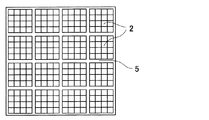
まず、SiCを主成分とするハニカム分体2のセラミックスの原料を秤量し、この原料を十分に混合(混練)した後に、軸方向に多数のセルが形成された柱状のSiCよりなる成形体を従来公知の製造方法である押出成形で製造した。この成形体は、断面が正方形状に区画されたセルをもつ。この成形体を図1に示した。
First, the ceramic raw material of the
つづいて、固形分がほぼSiC粉末よりなるスラリーを調製した。なお、このスラリーは、粘度調整材等の添加剤を含む。そして、このスラリーを、乾燥させた成形体の両端の端部から所定のセルに注入し、乾燥させた。ここで、所定のセルとは、スラリーが注入されたセルが市松模様状をなすようにもうけられている。また、セルの一方の端部または他方の端部のみにスラリーが注入された。 Subsequently, a slurry having a solid content of substantially SiC powder was prepared. This slurry contains additives such as a viscosity modifier. And this slurry was inject | poured into the predetermined cell from the edge part of the both ends of the dried molded object, and was dried. Here, the predetermined cell is provided so that the cell into which the slurry is injected has a checkered pattern. In addition, the slurry was injected only into one end or the other end of the cell.
そして、その後の工程で成形したときに、ハニカム構造体1の外周面を区画するセルには、その両端にスラリーを注入した。 And when it shape | molded at the subsequent process, the slurry was inject | poured into the cell which divides the outer peripheral surface of the honeycomb structure 1 into the both ends.
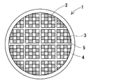
その後、2300℃でセルにスラリーが注入された成形体を熱処理して成形体を焼成するとともにスラリーを固化させて封止材3とし、封止材3で封止されたセル(封止部)をもつハニカム分体2を形成した。セルの軸方向における封止材3の長さはそれぞれ3.0mmであった。
Thereafter, the molded body in which the slurry is injected into the cell at 2300 ° C. is heat-treated to fire the molded body, and the slurry is solidified to form the sealing
製造されたハニカム分体2を、実施例の接合材を用いて接合した。接合材による接合は、厚さが1.0±0.5mmとなるように接合材をハニカム分体2の外周面に塗布した後、別のハニカム分体2をこの面にすりあわせて接合した。この接合を繰り返して、断面が正方形をなすようにハニカム分体2を接合し、80℃で乾燥した。これにより、ハニカム分体2が接合材層5を介して接合された接合体が形成された。ハニカム分体2の接合体の端面を図2に示した。
The manufactured
そして、この接合体を旋盤もしくは円筒研削機を用いて切削して外周形状を成形した。そして、主成分がSiCよりなるスラリーを調製し、成形体の外周面に塗布し、80℃で乾燥した後に850℃で加熱して接合材およびスラリーを固化させた。これにより、外周面上に外周材層4が形成できた。
The joined body was cut using a lathe or a cylindrical grinding machine to form an outer peripheral shape. And the slurry which a main component consists of SiC was prepared, and it apply | coated to the outer peripheral surface of a molded object, and after drying at 80 degreeC, it heated at 850 degreeC and solidified the joining material and the slurry. Thereby, the outer
以上により、本実施例のハニカム構造体1を製造することができた。本実施例のハニカム構造体をその端面で図3に示した。 As described above, the honeycomb structure 1 of this example could be manufactured. The honeycomb structure of the present example is shown in FIG.
本実施例のハニカム構造体1は、多孔質のSiCセラミックスよりなるハニカム分体2と、ハニカム分体2の間に位置し、ハニカム分体2同士をを接合するSiCハニカム用接合材層5と、を有する構成となっている。
A honeycomb structure 1 of the present embodiment includes a
(比較例1)
D50が38μmのSiC粉末(粗大粉末)、D50が0.8μmのSiC粉末(微細粉末)、1.5wt%でカルボキシルメチルセルロース(CMC)を含む水溶液よりなる有機バインダ、コロイダルシリカよりなる無機バインダを表1に示した割合で秤量し、混練した。ここで、SiC粉末やバインダは実施例において用いたものと同様なものを用いた。これにより、本比較例のSiCハニカム用接合材が調製された。
(Comparative Example 1)
D50 is a 38 μm SiC powder (coarse powder), D50 is a 0.8 μm SiC powder (fine powder), an organic binder made of an aqueous solution containing 1.5% by weight of carboxymethyl cellulose (CMC), and an inorganic binder made of colloidal silica. Weighed and kneaded at the ratio shown in 1. Here, the same SiC powder and binder as those used in the examples were used. Thereby, the bonding material for SiC honeycomb of this comparative example was prepared.
その後、実施例1の時と同様にして本比較例のハニカム構造体が製造できた。 Thereafter, the honeycomb structure of this comparative example could be manufactured in the same manner as in Example 1.
(比較例2)
D50が0.8μmのSiC粉末(微細粉末)、繊維長が1mm以下のムライトよりなる無機繊維、1.5wt%でカルボキシルメチルセルロース(CMC)を含む水溶液よりなる有機バインダ、コロイダルシリカよりなる無機バインダを表1に示した割合で秤量し、混練した。ここで、SiC粉末、無機繊維やバインダは実施例において用いたものと同様なものを用いた。これにより、本比較例のSiCハニカム用接合材が調製された。
(Comparative Example 2)
SiC powder (fine powder) having a D50 of 0.8 μm, inorganic fibers made of mullite having a fiber length of 1 mm or less, an organic binder made of an aqueous solution containing 1.5% by weight of carboxymethyl cellulose (CMC), and an inorganic binder made of colloidal silica They were weighed and kneaded at the ratio shown in Table 1. Here, the same SiC powder, inorganic fiber, and binder as those used in the examples were used. Thereby, the bonding material for SiC honeycomb of this comparative example was prepared.
その後、実施例の時と同様にして本比較例のハニカム構造体が製造できた。 Thereafter, the honeycomb structure of this comparative example could be manufactured in the same manner as in the example.
(評価)
実施例および各比較例のハニカム構造体の評価として、まず、接合材層の断面を走査型電子顕微鏡(SEM)で観察した。
(Evaluation)
As an evaluation of the honeycomb structures of Examples and Comparative Examples, first, a cross section of the bonding material layer was observed with a scanning electron microscope (SEM).
SEMによると、実施例および比較例1のハニカム構造体1では、図4に模式的に示したように、主に微細粉末よりなるハニカム分体2の表面との当接部を形成する表層部50と、表層部50の間に位置し主に粗大粉末と無機繊維とから構成され多数の細孔を有する中間層部51とが積層した構成であることが確認できた。これに対し、比較例2のハニカム構造体では、接合材層が細孔が形成されていない均一な構成となっていることが確認できた。
According to the SEM, in the honeycomb structure 1 of the example and the comparative example 1, as schematically shown in FIG. 4, a surface layer portion that forms a contact portion with the surface of the
つづいて、実施例及び各比較例の試料を作成し、熱衝撃試験を施した。 Subsequently, samples of Examples and Comparative Examples were prepared and subjected to a thermal shock test.
まず、実施例の時と同様にして、35×35×75mmの角柱状のハニカム分体を製造した。そして、接合材を1mmの厚さでハニカム分体の外周面に塗布し、別のハニカム分体2を貼り付けた。そして、合計9本のハニカム分体が3×3本で配された状態で接合された試料を実施例と同様に製造した。
First, in the same manner as in the example, a 35 × 35 × 75 mm prismatic honeycomb segment was manufactured. Then, the bonding material was applied to the outer peripheral surface of the honeycomb body with a thickness of 1 mm, and another
そして、内部の温度を調節できる加熱炉を準備し、炉内温度を600〜800℃の50℃ごとの所定の温度に加熱し保持する。炉内温度が所定の温度に保持されたことが確認できたら、試料を炉内に配置し、20分間保持する。 And the heating furnace which can adjust internal temperature is prepared, and the furnace temperature is heated and hold | maintained to the predetermined temperature for every 50 degreeC of 600-800 degreeC. When it is confirmed that the furnace temperature is maintained at a predetermined temperature, the sample is placed in the furnace and held for 20 minutes.
20分間保持した後に、炉内から試料を取り出し、急冷した。 After holding for 20 minutes, the sample was removed from the furnace and quenched.
放熱により、試料の温度が十分に低下するまで観察した。観察結果を表2に示した。表1においては、ハニカム体2にクラックおよびクラック音が確認できない場合には○で、ハニカム体2にクラックおよびクラック音が確認された場合には×で示した。
Observation was performed until the temperature of the sample sufficiently decreased due to heat dissipation. The observation results are shown in Table 2. In Table 1, when the crack and crack sound could not be confirmed in the
ここで、確認されるクラック音は、ほとんどの場合に高周波音の金属音であり、ハニカム分体2にクラックが生じている。また、表2においては、クラック音の確認とクラックの視認との間に温度差がある例がある。これらの例においては、クラック音が確認された時点で破壊が始まり、更に熱膨張して視認できるクラックが生じるものと推測できる。
Here, the crack sound to be confirmed is a high-frequency metallic sound in most cases, and cracks are generated in the
表2に示したように、実施例の試料は、各比較例の試料ではクラックが生じる温度である650℃以上に加熱しても、クラックが確認できなかった。つまり、実施例の試料は、各比較例よりも耐熱性に優れていることが確認できた。この耐熱性は、ハニカム分体間に形成された接合材層の中間層部の細孔がハニカム分体の体積変化を緩衝したことにより得られた。 As shown in Table 2, cracks could not be confirmed even when the samples of the examples were heated to 650 ° C. or higher, which is the temperature at which cracks occurred in the samples of each comparative example. That is, it was confirmed that the samples of the examples were superior in heat resistance than the comparative examples. This heat resistance was obtained because the pores in the intermediate layer portion of the bonding material layer formed between the honeycomb bodies buffered the volume change of the honeycomb bodies.
上記したように、実施例のハニカム構造体と同様な構成の試料では高い耐熱性(耐熱衝撃性)を有することが確認できたことから、実施例のハニカム構造体も高い耐熱性を有するものとなった。 As described above, since it was confirmed that the sample having the same structure as the honeycomb structure of the example had high heat resistance (thermal shock resistance), the honeycomb structure of the example also had high heat resistance. became.
このように、ハニカム分体を接合する接合材を特定の構成とすることで、接合材から形成される接合材層が細孔を有するものとなり、この細孔がハニカム分体の体積変化を緩衝し、ハニカム構造体が高い耐熱性を有するものとなった。 In this way, by adopting a specific configuration for the bonding material for bonding the honeycomb body, the bonding material layer formed from the bonding material has pores, and these pores buffer the volume change of the honeycomb body. Thus, the honeycomb structure has high heat resistance.
1:ハニカム構造体
2:ハニカム分体
3:封止材
4:外周材層
5:接合材層
1: Honeycomb structure 2: Honeycomb segment 3: Sealing material 4: Peripheral material layer 5: Bonding material layer
Claims (2)
該SiCハニカム用接合材は、
平均粒径(D50)が5μm以下のSiCよりなる微細粉末と、
平均粒径(D50)が5〜100μmのSiCよりなる粗大粉末と、
繊維長が10μm〜1mmの無機繊維と、
各該粉末および該無機繊維が分散した分散媒と、
有機バインダおよび/または無機バインダよりなるバインダと、
を有することを特徴とするSiCハニカム用接合材。 A bonding material for SiC honeycomb, in which a honeycomb structure made of porous SiC ceramics is bonded to form a honeycomb structure,
The SiC honeycomb bonding material is:
Fine powder made of SiC having an average particle size (D50) of 5 μm or less;
Coarse powder made of SiC having an average particle size (D50) of 5 to 100 μm;
An inorganic fiber having a fiber length of 10 μm to 1 mm;
A dispersion medium in which the powder and the inorganic fibers are dispersed;
A binder comprising an organic binder and / or an inorganic binder;
A bonding material for SiC honeycomb, comprising:
二つの該ハニカム分体の間に位置し、該ハニカム分体を接合するSiCハニカム用接合材層と、
を有するハニカム構造体であって、
該SiCハニカム用接合材層は、
平均粒径(D50)が5μm以下のSiCよりなる微細粉末と、
平均粒径(D50)が5〜100μmのSiCよりなる粗大粉末と、
繊維長が10μm〜1mmの無機繊維と、
各該粉末および該無機繊維が分散した分散媒と、
有機バインダおよび/または無機バインダよりなるバインダと、
を有する接合材より形成されたことを特徴とするハニカム構造体。 A honeycomb body made of porous SiC ceramics;
A bonding material layer for SiC honeycomb that is positioned between the two honeycomb bodies and bonds the honeycomb bodies;
A honeycomb structure having
The bonding material layer for SiC honeycomb is
Fine powder made of SiC having an average particle size (D50) of 5 μm or less;
Coarse powder made of SiC having an average particle size (D50) of 5 to 100 μm;
An inorganic fiber having a fiber length of 10 μm to 1 mm;
A dispersion medium in which the powder and the inorganic fibers are dispersed;
A binder comprising an organic binder and / or an inorganic binder;
A honeycomb structure formed from a bonding material having
Priority Applications (1)
| Application Number | Priority Date | Filing Date | Title |
|---|---|---|---|
| JP2007321143A JP2009143753A (en) | 2007-12-12 | 2007-12-12 | Bonding material for SiC honeycomb and honeycomb structure |
Applications Claiming Priority (1)
| Application Number | Priority Date | Filing Date | Title |
|---|---|---|---|
| JP2007321143A JP2009143753A (en) | 2007-12-12 | 2007-12-12 | Bonding material for SiC honeycomb and honeycomb structure |
Related Child Applications (1)
| Application Number | Title | Priority Date | Filing Date |
|---|---|---|---|
| JP2013054874A Division JP2013144640A (en) | 2013-03-18 | 2013-03-18 | Honeycomb structure |
Publications (1)
| Publication Number | Publication Date |
|---|---|
| JP2009143753A true JP2009143753A (en) | 2009-07-02 |
Family
ID=40914835
Family Applications (1)
| Application Number | Title | Priority Date | Filing Date |
|---|---|---|---|
| JP2007321143A Pending JP2009143753A (en) | 2007-12-12 | 2007-12-12 | Bonding material for SiC honeycomb and honeycomb structure |
Country Status (1)
| Country | Link |
|---|---|
| JP (1) | JP2009143753A (en) |
Cited By (1)
| Publication number | Priority date | Publication date | Assignee | Title |
|---|---|---|---|---|
| CN111747768A (en) * | 2019-03-27 | 2020-10-09 | 日本碍子株式会社 | Bonding material and silicon carbide honeycomb structure |
Citations (2)
| Publication number | Priority date | Publication date | Assignee | Title |
|---|---|---|---|---|
| WO2003067041A1 (en) * | 2002-02-05 | 2003-08-14 | Ibiden Co., Ltd. | Honeycomb filter for exhaust gas decontamination, adhesive, coating material and process for producing honeycomb filter for exhaust gas decontamination |
| JP2007191329A (en) * | 2006-01-17 | 2007-08-02 | Tokyo Yogyo Co Ltd | SiC bonding material |
-
2007
- 2007-12-12 JP JP2007321143A patent/JP2009143753A/en active Pending
Patent Citations (2)
| Publication number | Priority date | Publication date | Assignee | Title |
|---|---|---|---|---|
| WO2003067041A1 (en) * | 2002-02-05 | 2003-08-14 | Ibiden Co., Ltd. | Honeycomb filter for exhaust gas decontamination, adhesive, coating material and process for producing honeycomb filter for exhaust gas decontamination |
| JP2007191329A (en) * | 2006-01-17 | 2007-08-02 | Tokyo Yogyo Co Ltd | SiC bonding material |
Cited By (2)
| Publication number | Priority date | Publication date | Assignee | Title |
|---|---|---|---|---|
| CN111747768A (en) * | 2019-03-27 | 2020-10-09 | 日本碍子株式会社 | Bonding material and silicon carbide honeycomb structure |
| DE102020001820B4 (en) | 2019-03-27 | 2024-11-07 | Ngk Insulators, Ltd. | USE OF A BINDING MATERIAL FOR JOINING SIDE SURFACES OF MULTIPLE SILICON CARBIDE-BASED HONEYCOMB SEGMENTS |
Similar Documents
| Publication | Publication Date | Title |
|---|---|---|
| JP4870558B2 (en) | Honeycomb structure and sealing material layer | |
| JP5042632B2 (en) | Honeycomb structure | |
| JP5042633B2 (en) | Honeycomb structure | |
| JP5031562B2 (en) | Honeycomb structure | |
| CN100450577C (en) | Filters and Filter Assemblies | |
| JP5134377B2 (en) | Honeycomb segment and honeycomb structure | |
| JP5037809B2 (en) | Honeycomb structure | |
| WO2005063653A9 (en) | Honeycomb structure | |
| WO2003084640A1 (en) | Honeycomb filter for clarification of exhaust gas | |
| WO2006087932A1 (en) | Honeycomb structure | |
| JPWO2005026074A1 (en) | Ceramic sintered body and ceramic filter | |
| KR20060056269A (en) | Honeycomb structure and method of manufacturing the same | |
| KR20070088464A (en) | Honeycomb structure | |
| JP5103378B2 (en) | Honeycomb structure | |
| KR20060054439A (en) | Honeycomb structure and its manufacturing method | |
| JPWO2013125713A1 (en) | Honeycomb structure | |
| JP2001097777A (en) | Porous silicon carbide sintered product, honeycomb filter, ceramic filter assembly | |
| JP4997064B2 (en) | Bonding material composition and method for producing the same, joined body and method for producing the same | |
| JPWO2006098191A1 (en) | Honeycomb structure | |
| WO2009118810A1 (en) | Honeycomb structure | |
| JP2009196104A (en) | Honeycomb structure | |
| JP4402732B1 (en) | Honeycomb structure | |
| JP5190878B2 (en) | Honeycomb structure | |
| JP2013144640A (en) | Honeycomb structure | |
| US20090010817A1 (en) | Honeycomb filter |
Legal Events
| Date | Code | Title | Description |
|---|---|---|---|
| A621 | Written request for application examination |
Free format text: JAPANESE INTERMEDIATE CODE: A621 Effective date: 20101025 |
|
| A977 | Report on retrieval |
Free format text: JAPANESE INTERMEDIATE CODE: A971007 Effective date: 20111017 |
|
| A131 | Notification of reasons for refusal |
Free format text: JAPANESE INTERMEDIATE CODE: A131 Effective date: 20111101 |
|
| A521 | Request for written amendment filed |
Free format text: JAPANESE INTERMEDIATE CODE: A523 Effective date: 20111226 |
|
| A131 | Notification of reasons for refusal |
Free format text: JAPANESE INTERMEDIATE CODE: A131 Effective date: 20120619 |
|
| A521 | Request for written amendment filed |
Free format text: JAPANESE INTERMEDIATE CODE: A523 Effective date: 20120808 |
|
| A02 | Decision of refusal |
Free format text: JAPANESE INTERMEDIATE CODE: A02 Effective date: 20121218 |
|
| A521 | Request for written amendment filed |
Free format text: JAPANESE INTERMEDIATE CODE: A523 Effective date: 20130318 |
|
| A911 | Transfer to examiner for re-examination before appeal (zenchi) |
Free format text: JAPANESE INTERMEDIATE CODE: A911 Effective date: 20130326 |
|
| A912 | Re-examination (zenchi) completed and case transferred to appeal board |
Free format text: JAPANESE INTERMEDIATE CODE: A912 Effective date: 20130510 |