JP2009136397A - Intravenous catheter introducing device - Google Patents
Intravenous catheter introducing device Download PDFInfo
- Publication number
- JP2009136397A JP2009136397A JP2007313899A JP2007313899A JP2009136397A JP 2009136397 A JP2009136397 A JP 2009136397A JP 2007313899 A JP2007313899 A JP 2007313899A JP 2007313899 A JP2007313899 A JP 2007313899A JP 2009136397 A JP2009136397 A JP 2009136397A
- Authority
- JP
- Japan
- Prior art keywords
- plunger
- plunger body
- barrel
- barrel means
- needle seat
- Prior art date
- Legal status (The legal status is an assumption and is not a legal conclusion. Google has not performed a legal analysis and makes no representation as to the accuracy of the status listed.)
- Pending
Links
- 238000001990 intravenous administration Methods 0.000 title claims abstract description 75
- 238000003780 insertion Methods 0.000 claims description 74
- 230000037431 insertion Effects 0.000 claims description 74
- 230000002093 peripheral effect Effects 0.000 claims description 52
- 230000004308 accommodation Effects 0.000 claims description 16
- 238000009423 ventilation Methods 0.000 claims description 7
- 230000008602 contraction Effects 0.000 claims description 4
- 210000003462 vein Anatomy 0.000 claims description 3
- 239000008280 blood Substances 0.000 abstract description 15
- 210000004369 blood Anatomy 0.000 abstract description 15
- 210000004204 blood vessel Anatomy 0.000 description 10
- 101000793686 Homo sapiens Azurocidin Proteins 0.000 description 7
- 230000008878 coupling Effects 0.000 description 6
- 238000010168 coupling process Methods 0.000 description 6
- 238000005859 coupling reaction Methods 0.000 description 6
- 238000000034 method Methods 0.000 description 5
- 239000007788 liquid Substances 0.000 description 3
- 230000001012 protector Effects 0.000 description 2
- 230000007423 decrease Effects 0.000 description 1
- 239000003814 drug Substances 0.000 description 1
- 229940079593 drug Drugs 0.000 description 1
- 238000001802 infusion Methods 0.000 description 1
- 238000002347 injection Methods 0.000 description 1
- 239000007924 injection Substances 0.000 description 1
- 239000000203 mixture Substances 0.000 description 1
- 238000011084 recovery Methods 0.000 description 1
- 238000007789 sealing Methods 0.000 description 1
- 239000012780 transparent material Substances 0.000 description 1
Images
Landscapes
- Media Introduction/Drainage Providing Device (AREA)
Abstract
Description
本発明は静脈内カテーテル挿入装置に関し、特に、安全や衛生上の観点においてより優れた静脈内カテーテル挿入装置に関する。 The present invention relates to an intravenous catheter insertion device, and more particularly to an intravenous catheter insertion device that is superior in terms of safety and hygiene.
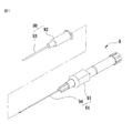
図1に示すのは静脈内カテーテル挿入装置の基本的な構成である。該静脈内カテーテル挿入装置9は、本体91に針カニューレ94が設けられている本体手段9Aと、カテーテルハブ92に可撓性カテーテル93が取り付られているカテーテル手段9Bとを備えてなる。
FIG. 1 shows a basic configuration of an intravenous catheter insertion device. The intravenous
針カニューレ94が可撓性カテーテル93に包まれるように本体手段9Aに取り付けられている使用待ち状態では、可撓性カテーテル93を針カニューレ94と共に患者の血管内に導入することができる。それから、カテーテル手段9Bの可撓性カテーテル93を患者の血管内に残したまま、本体手段9Aを抜き取れば、輸液器具または中空バレル(いずれも図示せず)をカテーテルハブ92に接続して薬剤の注射または採血を行うことができる。
In the ready-to-use state where the
しかし、上記従来の静脈内カテーテル挿入装置9では、カニューレ94が確かに患者の静脈に入ったか否かを確認する術がなく、操作を行う医療スタッフの経験で判断するしかない。従って、経験が足らない医療スタッフが操作ミスを犯す恐れがある。
更には、該従来の静脈内カテーテル挿入装置9を使用する際、抜き出されたカニューレ94及び本体91を隣に置いているトレー(図示せず)に置く必要があるが、この時露出しているカニューレ94の針先に刺される事故が発生する恐れがある。
However, in the conventional intravenous
Furthermore, when using the conventional intravenous
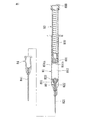
また、特開2005−312895号公報では、本発明者が前に発明した注射器を開示している。この注射器は、図2に示すように、透明材料からなるバレル手段81と、針カニューレ手段82と、プランジャ手段83とからなる。針カニューレ手段82は、針カニューレ821を保持する針座822及び針座822とバレル手段81の前端部811の間に介在する保持リング部823によって、バレル手段81の前端部811の管内に保持されている。プランジャ手段83のバレル手段81の後端にある開口から挿入する前端部831には、保持リング部823を前方へ押圧することによって保持リング部823と針座822の保持関係を解除できるように形成される押圧端831aと、針座822の後端と結合できるように形成され、且つプランジャ手段83の管内に取り付けられている結合ブロック831bとを有している。また、プランジャ手段83には針座822の後端と結合した結合ブロック831bを、針座822及び針カニューレ821をプランジャ手段83の後端側へ引き込むことができるばね832が取り付けられている。
Japanese Patent Application Laid-Open No. 2005-312895 discloses a syringe previously invented by the present inventor. As shown in FIG. 2, the syringe includes barrel means 81 made of a transparent material, needle cannula means 82, and plunger means 83. The needle cannula means 82 is held in the tube of the
上記基本的な構成の静脈内カテーテル挿入装置の問題点に対して、本発明者はこの特開2005−312895号公報に開示された注射器を静脈内カテーテル挿入装置の本体手段として利用すれば、上記2つの問題点を解決できるのではないかと考えた。
即ち、該注射器をプランジャ手段83の前端が針座822の近くに配置された状態で静脈内カテーテル挿入装置の本体手段として利用し、プランジャ手段83の後端にある操作端833を後方へゆっくり引きながら患者の体内に挿入する。患者の血液が針カニューレ821を経由して該注射器をプランジャ手段83の前端と針座822の間にあるチャンバー812内に吸入されると視認できれば、針カニューレ821が確実に患者の血管内に進入したと判断できる。
In response to the problem of the intravenous catheter insertion device having the above basic configuration, the present inventor can use the syringe disclosed in Japanese Patent Application Laid-Open No. 2005-312895 as the main body means of the intravenous catheter insertion device. I thought that two problems could be solved.
That is, the syringe is used as the body means of the intravenous catheter insertion device in a state where the front end of the plunger means 83 is arranged near the
また、前記静脈内カテーテル挿入装置9と同じ構成を有していて可撓性カテーテル841が該注射器の針カニューレ821を包むように取り付けられるカテーテル手段84は、前記可撓性カテーテル841を患者の血管内に残して本体手段としての該注射器を抜き取り、そしてプランジャ手段83を前方へ押し進み保持リング部823と針座822の保持関係を解除して針座822の後端と結合ブロック831bを結合させたら、ばね832はバレル手段81外に露出していた針カニューレ821を針座822及び結合ブロック831bと共にプランジャ手段83の後端側へ引き込むことができる。
Further, the catheter means 84 having the same configuration as that of the intravenous
しかし、この考案は基本的な構成の静脈内カテーテル挿入装置の問題点を解決できた一方、また新たな問題点が生じる。それが。針カニューレ821を引き込むには、針座822の後端と結合ブロック831bを結合させる必要があるが、これではプランジャ手段83の前端(結合ブロック831b)と針座822の間にあるチャンバー812内に吸入されたけ血液を収容する空間がなくなってしまい、行き場のない血液は唯一の出口である針カニューレ821の先端開口から射出されて環境を汚染する欠点が避けられない。
However, while this device can solve the problems of the basic configuration of the intravenous catheter insertion device, a new problem arises. that is. In order to retract the
従って、本発明は基本的な構成の静脈内カテーテル挿入装置の問題点と、本体手段として利用される針カニューレ引き込み式注射器が生み出す問題点を一斉に解決できる静脈内カテーテル挿入装置を提供することを目的とする。 Accordingly, the present invention provides an intravenous catheter insertion device that can simultaneously solve the problems of the intravenous catheter insertion device of the basic configuration and the problems generated by the needle cannula retractable syringe used as the body means. Objective.
上記目的を達成するため、本発明は、所定の軸線方向をしてその前端(132)に開口が形成された管状の小径部(134)と、同軸線方向をして後端(131)に開口が形成された管状の大径部(133)と、前記小径部の後端と前記大径部の前端の間に介在して前記大径部から前記小径部へ縮径する接合部(135)とにより形成された管状のバレル手段(1)と、前端が針先端(231)として鋭く形成された針カニューレ(23)と、略管状に形成されて前記針カニューレを外周より固持し、前記バレル手段に対する更なる前方への移動が所定範囲内に制限されるように、前記バレル手段内の前端近くに配置されている針座(22)と、前記針座を嵌挿させるようにリング状に形成されて前記針座の外周面と前記バレル手段の内周面の間に介在し、前記針座の前記バレル手段に対する更なる後方への移動を制限するように前記針座を保持し、後方からの押圧力を受けて前記バレル手段に対して前方へ押し進まれると、前記針座の前記バレル手段に対する後方へ移動を可能にするようになる保持リング(21)と、を備えている針カニューレ手段(2)と、前記バレル手段の軸線方向に沿って前記バレル手段の大径部内に前後摺動可能に嵌挿し、その前端に開口を有する中空の管状体で、後方から前記バレル手段の後端開口に差し込まれ、前端面が前記保持リングに当接して前記保持リングを前記バレル手段に対して前方へ押し進むことができるプランジャ体(32)と、前記プランジャ体に対する更なる前方への移動が制限されるよう、そして前方からの押圧力を受けて前記プランジャ体に対して後方へ押されると、前記プランジャ体から取り外されるように前記プランジャ体内の前端近くに取り付けられると共に、その前端部が前記プランジャ体のバレル手段に対する相対運動に従って前進して前記針座の後端部に当接して接続できる後接続端部として形成されており、前記後接続端部に設けられて前記プランジャ体の前端開口と連通する開口と、前記プランジャ体の管内空間と連通して気体の行き来だけを許す第1の通気口とを有するように中空の管状体に形成される収容ユニット(34)と、を備えているプランジャ手段と、前記プランジャ手段のプランジャ体がユーザの操作によって前記バレル手段に対して前進し、前記プランジャ体の前端面が前記保持リングに当接して前記保持リングを前記バレル手段に対して前方へ押し進んで前記針座の前記バレル手段に対する後方への移動を可能にし、そして前記プランジャ手段が引き続き前進して前記収容ユニットの後接続端部が前記針座の後端部に当接し、そして前記収容ユニットが前方への移動が所定範囲に到達して前進できなくなる前記針座に突き当てられて前記プランジャ体から外されると、前記針座に固定されている前記針カニューレを露出しないように前記バレル手段内に収容するよう、前記収容ユニットと前記針座とを前記プランジャ体の後端へ移動する付勢力を提供する付勢手段(4)とを有していることを特徴とする静脈内カテーテル挿入装置を提供する。 In order to achieve the above object, the present invention provides a tubular small-diameter portion (134) having an opening at its front end (132) in a predetermined axial direction, and a rear end (131) in a coaxial line direction. A tubular large-diameter portion (133) in which an opening is formed, and a joint portion (135) interposed between the rear end of the small-diameter portion and the front end of the large-diameter portion to reduce the diameter from the large-diameter portion to the small-diameter portion. And a tubular barrel means (1) formed by the above-mentioned structure, a needle cannula (23) whose front end is sharply formed as a needle tip (231), and is formed in a substantially tubular shape to hold the needle cannula from the outer periphery, A needle seat (22) disposed near the front end in the barrel means so that further forward movement with respect to the barrel means is limited within a predetermined range, and a ring shape so that the needle seat is inserted. Formed on the outer peripheral surface of the needle seat and the inner peripheral surface of the barrel means The needle seat is interposed so as to limit further rearward movement of the needle seat relative to the barrel means, and is pushed forward with respect to the barrel means under a pressing force from the rear. And a needle cannula means (2) comprising a retaining ring (21) adapted to allow the needle seat to move rearward relative to the barrel means; and the barrel along the axial direction of the barrel means A hollow tubular body that is slidably inserted in the large-diameter portion of the means and has an opening at the front end thereof, and is inserted into the rear end opening of the barrel means from the rear, and the front end surface abuts the holding ring and A plunger body (32) capable of pushing the retaining ring forward relative to the barrel means, and further forward movement relative to the plunger body is restricted and subjected to a pressing force from the front. When pushed backward with respect to the plunger body, the needle body is attached near the front end of the plunger body so as to be removed from the plunger body, and the front end portion thereof moves forward according to relative movement of the plunger body with respect to the barrel means. An opening provided at the rear connection end and communicating with the front end opening of the plunger body; and communicating with a space in the pipe of the plunger body. And a housing unit (34) formed in a hollow tubular body so as to have a first vent that allows only gas to pass back and forth, and the plunger body of the plunger means is operated by a user. The front end surface of the plunger body abuts on the holding ring to move the holding ring to the barrel means. And the plunger means continues to advance so that the rear connecting end of the receiving unit is at the rear end of the needle seat. The needle cannula fixed to the needle seat when it comes into contact with the needle seat and comes into contact with the needle seat so that it cannot move forward because the forward movement reaches a predetermined range. And a biasing means (4) for providing a biasing force for moving the storage unit and the needle seat to the rear end of the plunger body so as to be accommodated in the barrel means so as not to be exposed. An intravenous catheter insertion device is provided.
(共通・図3、5参照)上記静脈内カテーテル挿入装置において、前記保持リング(21)の前記針座(22)の外周面と接する内周面と、前記バレル手段(1)の内周面と接する外周面には、それぞれ第1のリング溝(211)と第2のリング溝(212)が形成されており、そして前記針座(22)の外周面の後端近くと前記バレル手段(1)の大径部(133)の内周面の前端近くには、それぞれ前記第1のリング溝と前記第2のリング溝に対応して嵌め込むことによって前記針座を前記バレル手段に対して後方へ移動できないように保持することができる第1のリング条(222)と第2のリング条(137)が形成されていることが好ましい。 (See Common, FIGS. 3 and 5) In the intravenous catheter insertion device, the inner peripheral surface of the holding ring (21) contacting the outer peripheral surface of the needle seat (22) and the inner peripheral surface of the barrel means (1) A first ring groove (211) and a second ring groove (212) are formed on the outer peripheral surface in contact with each other, and near the rear end of the outer peripheral surface of the needle seat (22) and the barrel means ( 1) Near the front end of the inner peripheral surface of the large-diameter portion (133), the needle seat is fitted to the barrel means by being fitted in correspondence with the first ring groove and the second ring groove, respectively. It is preferable that a first ring strip (222) and a second ring strip (137) that can be held so as not to move backward are formed.
上記静脈内カテーテル挿入装置において、前記バレル手段には、前記小径部の内周面から内側に突出させた段部(139)を有しており、前記針座の前端には、前記段部に対応して前方に面して、該段部に当接すると前記バレル手段に対する更なる前方への移動が制限される針座当接段部(221)が形成されていることが好ましい。 In the above intravenous catheter insertion device, the barrel means has a step portion (139) protruding inwardly from the inner peripheral surface of the small diameter portion, and at the front end of the needle seat, Correspondingly, facing the front, it is preferable to form a needle seat abutting step (221) in which further forward movement relative to the barrel means is restricted when abutting against the step.
上記静脈内カテーテル挿入装置において、その前端(411)が前記バレル手段の前記小径部の先端壁の内側後方に面したバレル当接段部(141)に当接し、その後端(412)が前記針座の針座当接段部に当接するように縮設されているコイルスプリング(41)を前記付勢手段として、該コイルスプリングの伸張力を前記付勢力として利用することができる。 In the intravenous catheter insertion device, the front end (411) abuts on the barrel contact step (141) facing the inner rear side of the distal end wall of the small diameter portion of the barrel means, and the rear end (412) is the needle. A coil spring (41) that is contracted so as to contact the needle seat contact step of the seat can be used as the biasing means, and the extension force of the coil spring can be used as the biasing force.
また、その両端が前記バレル手段の前記大径部の前端近くと、前記収容ユニットの外周面の後端近くとの間に縮設されるコイルスプリングを前記付勢手段として、該コイルスプリングの伸張力を前記付勢力として利用することもできる。 Further, the coil spring is extended by using a coil spring whose both ends are near the front end of the large diameter portion of the barrel means and near the rear end of the outer peripheral surface of the housing unit as the biasing means. Force can also be used as the biasing force.
更に、その前端(421)が前記収容ユニットの前端近くに取り付けられ、後端(422)が前記バレル手段の前記大径部の後端近くに取り付けられるように配置されている引張りコイルスプリング(42)を前記付勢手段として、該引張りコイルスプリングの収縮力を前記付勢力として利用することもできる。 Further, a tension coil spring (42) arranged such that its front end (421) is attached near the front end of the receiving unit and its rear end (422) is attached near the rear end of the large diameter portion of the barrel means. ) As the biasing means, and the contraction force of the tension coil spring can be used as the biasing force.
更にまた、前記プランジャ手段には、前記プランジャ体の後端部に取り付けられている操作端キャップ(37)を更に有し、その前端が前記収容ユニットの外周面の前端近くに取り付けられ、後端が前記プランジャ手段の前記操作端キャップ(37)に取り付けられるように配置されている引張りコイルスプリングを前記付勢手段として有し、該引張りコイルスプリングの収縮力を前記付勢力として利用することもできる。 Furthermore, the plunger means further includes an operation end cap (37) attached to the rear end portion of the plunger body, the front end of which is attached near the front end of the outer peripheral surface of the housing unit. Can be used as the biasing means, and the contracting force of the tension coil spring can be used as the biasing force. .
上記静脈内カテーテル挿入装置において、前記プランジャ手段の収容ユニットが有する前記第1の通気口(344)が気体の行き来だけを許すことができるように、前記第1の通気口を覆うように取り付けて液体を通さず気体だけ通過させるフィルター(35)を更に備えていることが好ましい。 In the intravenous catheter insertion device, the first ventilation port (344) of the accommodation unit of the plunger means is attached so as to cover the first ventilation port so that only the flow of gas can be allowed. It is preferable to further include a filter (35) that allows only gas to pass therethrough without passing liquid.
上記静脈内カテーテル挿入装置において、前記バレル手段の大径部の筒内は、前記プランジャ体の外周面との間に、前記プランジャ体の自在な前後摺動を可能にする隙間が確保されており、そして前記プランジャ体の前端部には、該隙間を水密に塞ぐと共に、前記保持リングを前記バレル手段に対して前方へ押し進んで前記針座の前記バレル手段に対する後方への移動を可能にする前端面を有しているシール部材(36)が取り付けられていることが好ましい。 In the above-mentioned intravenous catheter insertion device, a gap that allows the plunger body to freely slide back and forth is secured between the inside of the cylinder of the large diameter portion of the barrel means and the outer peripheral surface of the plunger body. In addition, the front end portion of the plunger body closes the gap in a watertight manner and pushes the holding ring forward with respect to the barrel means to allow the needle seat to move backward with respect to the barrel means. A sealing member (36) having a front end face is preferably attached.
上記静脈内カテーテル挿入装置において、前記プランジャ手段のプランジャ体には、該プランジャ体管内空間を外部と連通し、且つユーザによって自由に塞ぐことができる第2の通気口(33)を有するように形成されていることが好ましい。 In the above intravenous catheter insertion device, the plunger body of the plunger means is formed to have a second ventilation hole (33) that allows the plunger body inner space to communicate with the outside and can be freely closed by the user. It is preferable that
また、前記第2の通気口は、前記プランジャ体の後端近くに、ユーザが指で自由に塞ぐことができるように形成されることもできる。 The second vent may be formed near the rear end of the plunger body so that the user can freely close it with a finger.
更に、前記第2の通気口は、前記プランジャ体の後端に後方に向けて開口し、ユーザが指で自由に塞ぐことができるように形成されることもできる。 Further, the second ventilation hole may be formed to open rearward at the rear end of the plunger body so that the user can freely close it with a finger.
更に、前記第2の通気口は、管状体に形成された前記プランジャ体の後端開口として、ユーザが指で自由に塞ぐことができるように形成されることができる。 Furthermore, the second vent hole can be formed as a rear end opening of the plunger body formed in a tubular body so that the user can freely close it with a finger.
また、前記第2の通気口が管状体に形成された前記プランジャ体の後端開口として形成される静脈内カテーテル挿入装置については、ユーザの操作により該第2の通気口を自由に塞ぐことができる取外し可能のカバーを更に有するように形成されることが好ましい。 In addition, regarding an intravenous catheter insertion device in which the second vent is formed as a rear end opening of the plunger body formed in a tubular body, the second vent can be freely closed by a user operation. It is preferably formed to further have a removable cover that can.
また、前記第2の通気口が管状体に形成された前記プランジャ体の後端開口として形成される静脈内カテーテル挿入装置において、前記プランジャ体の後端開口近くの内周面には、前記付勢手段の付勢力により移動して来た前記収容ユニットが該第2の通気口から出られないよう、内側に突起して前記収容ユニットの移動を阻止できるストッパー(327)が更に形成されることが好ましい。 Further, in the intravenous catheter insertion device in which the second vent is formed as a rear end opening of the plunger body formed in a tubular body, an inner peripheral surface near the rear end opening of the plunger body is provided on the inner peripheral surface. A stopper (327) that protrudes inward and prevents movement of the storage unit is further formed so that the storage unit that has been moved by the urging force of the urging means does not come out of the second vent. Is preferred.
更に、本発明の静脈内カテーテル挿入装置において、前記バレル手段に取り外せるように装着されているカテーテルハブ(51)と、前記カテーテルハブに設けられ、前記針カニューレのバレル手段から露出する根元の部分を把持して針先端を露出させる可撓性カテーテル(52)とを備えているカテーテル手段(5)を更に有することが好ましい。 Furthermore, in the intravenous catheter insertion device of the present invention, a catheter hub (51) mounted so as to be removable from the barrel means, and a root portion provided on the catheter hub and exposed from the barrel means of the needle cannula. It preferably further comprises catheter means (5) comprising a flexible catheter (52) that grips and exposes the needle tip.
また、本発明の静脈内カテーテル挿入装置において、前記プランジャ手段には、前記プランジャ体の外周面からわずかに外側に突起するように形成されたリング突起(325)を有し、前記バレル手段の大径部の内周面には、前記リング突起に対応して前記リング突起との係合によって前記プランジャ手段の前記バレル手段に対する後退移動を阻止することができるリング溝(136)を有することが好ましい。 In the intravenous catheter insertion device of the present invention, the plunger means has a ring protrusion (325) formed so as to protrude slightly outward from the outer peripheral surface of the plunger body, and the barrel means is large. It is preferable that the inner peripheral surface of the diameter portion has a ring groove (136) that can prevent the plunger means from retreating relative to the barrel means by engaging with the ring protrusion corresponding to the ring protrusion. .
また、本発明の静脈内カテーテル挿入装置において、前記プランジャ手段が前記バレル手段に対して前記収容ユニットが前記針座に突当てられて前記プランジャ体から抜けるよう前進したのち、前記バレル手段の後端開口周縁に当接して前記プランジャ体の更なる前進を制限するよう、前記プランジャ体の外周面から外側に突起するように形成される制限リング条(324)を更に有することが好ましい。 Further, in the intravenous catheter insertion device of the present invention, the plunger means moves forward with respect to the barrel means so that the accommodation unit is abutted against the needle seat and comes out of the plunger body, and then the rear end of the barrel means It is preferable to further have a restricting ring (324) formed so as to protrude outward from the outer peripheral surface of the plunger body so as to abut against the peripheral edge of the opening and restrict further advancement of the plunger body.
上記構成によれば、本発明は通常の注射器と同じように針カニューレが患者の血管に進入したかどうかを、血液のバレル内に流れ込むことを見て確認することができ、そして使用後にバレル手段外に露出していた針カニューレをバレル手段内に引き込むことによって針カニューレの針先に刺される事故の発生確率を抑えることができる。その上、バレル手段内におけるプランじゃ手段と針カニューレ手段の間に吸い込まれた血液を収容ユニット内に収容すると共に、収容しきれなかった空気をプランジャ管壁や後端の第2の通気口から排出することができるので、血液が針カニューレの先端開口から射出して環境を汚染する恐れもなくなる。 According to the above configuration, the present invention can confirm whether the needle cannula has entered the patient's blood vessel as if it were a normal syringe by seeing it flow into the blood barrel and after use the barrel means By pulling the needle cannula exposed to the outside into the barrel means, it is possible to suppress the probability of occurrence of an accident where the needle tip of the needle cannula is stuck. In addition, in the plan in the barrel means, the blood sucked between the means and the needle cannula means is accommodated in the accommodating unit, and the air that has not been accommodated is drawn from the plunger tube wall and the second vent at the rear end. Since it can be drained, there is no risk of blood being ejected from the tip opening of the needle cannula and contaminating the environment.
以下は図面を参照しながら本発明の各実施形態について詳しく説明する。 Hereinafter, embodiments of the present invention will be described in detail with reference to the drawings.
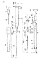
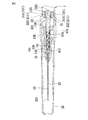
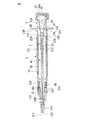
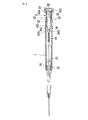
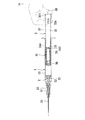
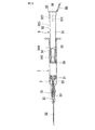
まず、図3〜図5は本発明の第1の実施形態の静脈内カテーテル挿入装置の構成を示している。図3は該静脈内カテーテル挿入装置の組み立てる前の分解断面図で、図4は組み立てた全体の状態を示す断面図で、図5は針カニューレ手段の周辺構成を示す拡大断面図である。 First, FIGS. 3-5 has shown the structure of the intravenous catheter insertion apparatus of the 1st Embodiment of this invention. FIG. 3 is an exploded cross-sectional view of the intravenous catheter insertion device before assembly, FIG. 4 is a cross-sectional view showing the assembled state, and FIG. 5 is an enlarged cross-sectional view showing the peripheral configuration of the needle cannula means.
図3〜図5に示すように、該第1の実施形態の静脈内カテーテル挿入装置は、主に、各部材を収容するまたは取り付けられる本体部としてのバレル手段1と、針カニューレ23と針カニューレ23をバレル手段1に取り付けるための各部材からなる針カニューレ手段2と、ユーザが操作する操作端を有して各部材の作動を制御するプランジャ手段3と、針カニューレ23をバレル手段1内に引き込んで収容する付勢力を提供する付勢手段4と、バレル手段1及び針カニューレ手段2に取り付けられるカテーテル手段5とを備えてなる。
As shown in FIGS. 3 to 5, the intravenous catheter insertion device of the first embodiment mainly includes a barrel means 1 as a main body portion that accommodates or attaches each member, a
バレル手段1は図3に示すように、所定の軸線方向を包囲して前端132に針カニューレ23が前方へ延伸して露出する開口が形成された管状の小径部134と、同じく前記軸線方向を包囲して後端131にプランジャ手段3が挿入する開口が形成された管状の大径部133と、小径部134の後端と大径部133の前端の間に介在し、大径部133から小径部134へ縮径して形成される接合部135とを有する管状体に形成されている。
As shown in FIG. 3, the barrel means 1 includes a tubular small-
その他、大径部133の内周面の前端近くに形成されて針カニューレ手段2と係合して針カニューレ手段2を一時的に固定するための第2のリング条137と、大径部133の内周面の後端近くに形成されてプランジャ手段3と係合することによって、プランジャ3のバレル手段1に対する後方への移動を制限して再利用を防ぐリング溝136と、大径部133の後端131から外側に張り出して形成される指当てフランジ138と、小径部134の内周面の接合部135に近い位置から内側に張り出して後方に面するように形成されるて針カニューレ手段2の針座22(後述)に当接するための段部139とを有している。
In addition, a
針カニューレ手段2は、図3と図4に示すように、前端が針先端231として鋭く形成される針カニューレ23と、略管状に形成されて針カニューレ23の後端部を包囲して固持し、外周面に形成されて保持リング21(後述)と係合するための第1のリング条222と、プランジャ手段3の収容ユニット34(後述)と接続して結合できるように後端部に形成される前接続端部223と、バレル手段1の小径部に形成される段部139に対応して前方に面するように前端に形成される針座当接段部221と、該針座当接段部221の内側から前方へ突起するように形成されてバレル手段1の小径部134の内周面と共に付勢手段4としてのコイルスプリング41(後述)の位置を固定する管状部224とを有している針座22と、リング状に形成され、そのリングの内周面に針座22の第1のリング条222と係合できるように形成される第1のリング溝211を有すると共に、外周面にバレル手段1の大径部133に形成される第2のリング条137と係合できるように形成される第2のリング溝212を有している保持リング21とを備えている。
As shown in FIGS. 3 and 4, the needle cannula means 2 has a
針座22は、図4と図5に示す使用前の状態において、針座当接段部221がバレル手段1の小径部に形成される段部139と所定距離の間隔を開けるように配置されており、そして後方からの押圧力を受けて前進して該段部139と当接すると、バレル手段1に対する更なる前進が出来なくなる。また、保持リング21は第1のリング条222と第1のリング溝211との係合で針座22を保持する一方、第2のリング条137と第2のリング溝212との係合でバレル手段1の大径部133内に保持されている。そして、保持リング21は、針座22及び大径部133との係合によって、大径部133内における保持リング21の前側と後側の空間を連通しないようにするシールとしての役割も果たしている。
The
この構成によって、保持リング21が後方からの押圧力を受けてバレル手段1に対して前方に移動すると、針座22も保持リング21と共に前進するが、バレル手段1の小径部に形成される段部139と当接するとバレル手段1に対する更なる前方への移動が制限される。一方、保持リング21の直前には障害物がなく、まだ前進できるので、第1のリング条222と第1のリング溝211との係合が解除されるようになり、針座22のバレル手段1に対する後方へ移動が許されるようになる。
With this configuration, when the holding
プランジャ手段3は、バレル手段1の軸線方向に沿ってバレル手段の大径部133の後端131から大径部133内に挿し込まれて前後摺動できる前後両端にを開口を有する中空の管状体に形成されるプランジャ体32と、プランジャ体32に対する更なる前方への移動が制限され、そして前方からの押圧力を受けてプランジャ体32に対して後方へ押されると、プランジャ体32から取り外されるようにプランジャ体32内の前端近くに取り付けられる収容ユニット34と、プランジャ体32の後端開口を塞ぐことができる操作端キャップ37とを備えている。
The plunger means 3 is a hollow tubular tube having openings at the front and rear ends that are inserted into the
また、プランジャ体32は、大径部133内の自在な前後摺動を可能にする隙間を確保するため、バレル手段1の大径部133の内周面よりやや小径に形成され、そしてその前端部には、該隙間を水密に塞ぐと共に、前方に配置されている保持リング21をバレル手段1に対して前方へ押し進んで針座22のバレル手段1に対する後方への移動を可能にする前端面361を有しているシール部材36が取り付けられ、更に後端に取り付けられているキャップ37の近くには、管内空間31を外部と連通し、且つユーザの指(図6参照)によって自由に塞ぐことができる第2の通気口33を有するように形成されている。
The
更に、プランジャ体32の外周面には、バレル手段1の後端131の開口周縁に当接すると、プランジャ体32のバレル手段1に対する更なる前進を制限する制限リング条324が突起するように形成されている。
Further, on the outer peripheral surface of the
また、収容ユニット34は前後両端にそれぞれプランジャ体32の前端開口と、プランジャ体32の管内空間31と連通する開口を有する管状体に形成され、そして前端部に形成されて針座22の前接続端部223を受け入れて接続結合できる後接続端部343と、中段部に形成されてプランジャ体32と係合してプランジャ体32に対する前方への移動を制限する係合突起341と、プランジャ体32の管内空間31と連通する開口で、液体を通さず気体だけ通過させるフィルター35により覆われている第1の通気口344とを有している。
The
この構成によって、プランジャ手段3のバレル手段1に対する前進行程において、バレル手段1内のプランジャ手段3の前方にある液体や気体はプランジャ体32及び収容ユニット34の前端開口を経由して収容ユニット34の管内に進入して収容されるようになる。そして、気体だけ更にフィルター35を通過してプランジャ手段3の管内空間31と第2の通気口33とを経由して外部に排出することができる。
With this configuration, in the forward travel of the plunger means 3 relative to the barrel means 1, the liquid or gas in front of the plunger means 3 in the barrel means 1 passes through the
ちなみに、プランジャ体32のバレル手段1に対する更なる前進を制限する制限リング条324は、プランジャ手段3の収容ユニット34がバレル手段1の段部139に当接するため前進できない針座22に阻まれて針座22に突き当てられてプランジャ体32から取り外されるまで前進すると、ちょうどバレル手段1の後端131の開口周縁に当接できる位置に設けられている。
Incidentally, the limiting
付勢手段4として取り付けられるコイルスプリング41は、前端411がバレル手段1の前端132の近くに後方に面するように形成されるバレル当接段部141に当接するように取り付けられ、後端412が針座22の管状部224と小径部134の内周面の間に入り込んで針座当接段部221に当接するようにバレル手段1の小径部134内に縮設されている。
The
この構成によって、針座22の保持リング21との係合と収容ユニット34のプランジャ体32との係合とが両方解除されてバレル手段1に対する後方への移動が許されると、コイルスプリング41の後端412も解放されるようになってその伸張力を用いて針座22と収容ユニット34と針カニューレ23を後方へ移動することができる。
With this configuration, when both the engagement of the
カテーテル手段5は、バレル手段1の小径部に取り外せるようにキャップ状に装着されているカテーテルハブ51と、カテーテルハブ51の前端に設けられ、カテーテルハブ51がバレル手段1に取り付けられている状態において、針カニューレ23のバレル手段1から露出する根元の部分を包んで針先端231を露出させる可撓性カテーテル52とからなる。
The catheter means 5 is provided at the front end of the
また、この実施形態では使用前状態でバレル手段1の前端外に露出している針カニューレを保護するするキャップ状で取り外し可能のプロテクター26を有している。
In this embodiment, the
続いて、図6から図10を参照して本実施形態の使用方法について詳しく説明する。 Next, the usage method of the present embodiment will be described in detail with reference to FIGS.
図6に示すように、プランジャ手段3の前端が保持リング21の近くに配置される状態で、針カニューレ23の針先端231が患者の皮膚に刺し込んで、ユーザが指てプランジャ手段3の第2の通気口33を塞いでゆっくりプランジャ手段3をバレル手段から引き抜くように操作すると、バレル手段1の大径部133内における保持リング手段21の後側の圧力は容積の増大と共に下がるので、針カニューレ23に経由してバレル手段1の大径部133内に吸い込んだ血液の勢いで針カニューレ23の針先端231が確かに患者の血管内に挿入したか否かを判断することができる。また、この操作で採血を行うこともできる。
As shown in FIG. 6, the
針カニューレ23の針先端231が確かに患者の血管内に挿入したと判断したら、針カニューレ23をカテーテル手段5の可撓性カテーテル52も血管内に挿入するまで挿入し、そして図7示すように、カテーテル手段5のカテーテルハブ51をバレル手段1から取り外し、カテーテル手段5の可撓性カテーテル52を患者の血管内に残したまま、針カニューレ23を患者の皮膚から抜き取る。患者の皮膚から抜き取った静脈内カテーテル挿入装置のプランジャ手段3をシール部材36が保持リング21に当接するまで押し込むと、大径部133内における保持リング21とプランジャ手段3の間にあった空気と血液は、プランジャ体32及び収容ユニット34の前端開口を経由して収容ユニット34の管内に進入して収容されるようになる。プランジャ体32の管内と収容ユニット34が収容し切れなかった空気は、図7における矢印が示すルート、即ち、プランジャ手段3の管内空間31及び第2の通気口33を経由して外部に排出することができる。よって、大径部133内における保持リング21とプランジャ手段3の間に吸い込まれた血液が逆に針カニューレ23から射出されて環境を汚染する恐れもなくなる。
If it is determined that the
更に、ユーザが引き続けてプランジャ手段3をバレル手段1に押し込むと、図8に示すように、保持リング21はプランジャ体32の前端部に取り付けられるシール部材36の前端面361によって前方へ押し進まれて針座22の後方への移動を許し、一方、前方への移動が針座22によって阻まれた収容ユニット34は、前端部に形成される後接続端部343が針座22の後端部に形成される前接続端部223と接続すると共に、プランジャ体32に対して後方へ移動して取り外される。更に、プランジャ体32の外周面の後端近くからわずかに外側に突起するように形成されるリング突起325は、大径部133の内周面の後端近くに形成されるリング溝136に嵌めこんでプランジャ体32のバレル手段1に対する更なる後方への移動を制限し、そして一方制限リング条324はバレル手段1の後端131の開口周縁に当接することによってプランジャ体32のバレル手段1に対する更なる前進を制限しているので、プランジャ体32のバレル手段1に対する前進も後退も出来なくなり、該静脈内カテーテル挿入装置の再利用を防ぐことができる。
Further, when the user continues to pull and pushes the plunger means 3 into the barrel means 1, the retaining
図8に示す状態になると、針座22のバレル手段1に対する後方への移動が許され、そして針座22の後側にある収容ユニット34のプランジャ体32に対する後方への移動も許されるので、付勢手段4として取り付けられるコイルスプリング41の針座22の針座当接段部221に当接する後端412は、図9に示すように、その回復伸張力を用いて針座22と収容ユニット34と針カニューレ23を、収容ユニット34の後端がプランジャ体32の後端に取り付けられている操作端キャップ37に当接するまで後方へ移動して、針カニューレ23の針先はし231までバレル手段1内に収容することによって、針カニューレ23の針先はし231に刺される事故の発生確率を下げるように図る。また、この状態において、更に操作端キャップ37をプランジャ体32から取り外すと、収容ユニット34をバレル手段1及びプランジャ体32から取り出して処理することができる。
When the state shown in FIG. 8 is reached, the
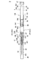
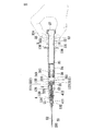
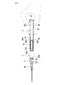
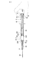
次いで、図10、11に示すのは本発明の静脈内カテーテル挿入装置の第2の実施形態である。この第2の実施形態は第1の実施形態と類似する構成を有するが、付勢手段4として取り付けられるコイルスプリング41は、前端411がプランジャ手段3のプランジャ体32に取り付けられ、後端412がプランジャ手段3の収容ユニット34の後端から外側に張り出して形成されると共に、プランジャ体32と解除可能に係合する当接フランジ342に当接するようにプランジャ体32の管内に縮設されている。
Next, FIGS. 10 and 11 show a second embodiment of the intravenous catheter insertion device of the present invention. The second embodiment has a configuration similar to that of the first embodiment, but the
この構成によると、図11に示すように、針座22の後端部に形成される前接続端部223が収容ユニット34の前端部に形成される後接続端部343とが接続して結合する上、針座22の保持リング21との係合と収容ユニット34の当接フランジ342のプランジャ体32ととが両方解除されてバレル手段1に対する後方への移動が許されると、コイルスプリング41の後端412も解放されるようになって第1の実施形態と同じくその伸張力を用いて針座22と収容ユニット34と針カニューレ23を後方へ移動することができる。
According to this configuration, as shown in FIG. 11, the
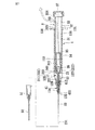
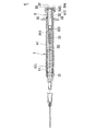
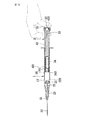
次いで、図12、13に示すのは本発明の静脈内カテーテル挿入装置の第3の実施形態である。この第3の実施形態は第1の実施形態と類似する構成を有するが、付勢手段4として取り付けられる引張りコイルスプリング42は、引っ張られた状態で、前端421がプランジャ手段3の収容ユニット34の前端近くに設けられる係合突起341に固定され、後端422がプランジャ手段3のプランジャ体32の後端近くに固定されるようにプランジャ体32の管内に配置されている。
この構成によると、図13に示すように、針座22の後端部に形成される前接続端部223が収容ユニット34の前端部に形成される後接続端部343とが接続して結合する上、針座22の保持リング21との係合と収容ユニット34のプランジャ体32との係合とが両方解除されてバレル手段1に対する後方への移動が許されると、引張りコイルスプリング42の前端421も解放されるようになってその収縮力を用いて針座22と収容ユニット34と針カニューレ23を後方へ移動することができる。
Next, FIGS. 12 and 13 show a third embodiment of the intravenous catheter insertion device of the present invention. The third embodiment has a configuration similar to that of the first embodiment, but the
According to this configuration, as shown in FIG. 13, the
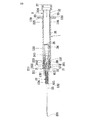
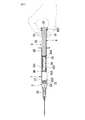
次いで、図14に示すのは本発明の静脈内カテーテル挿入装置の第4の実施形態である。この第4の実施形態は第3の実施形態と類似する構成を有するが、付勢手段4として取り付けられる引張りコイルスプリング42の後端422が、プランジャ手段3の操作端キャップ37に固定されている。
Next, FIG. 14 shows a fourth embodiment of the intravenous catheter insertion device of the present invention. The fourth embodiment has a configuration similar to that of the third embodiment, but the
次いで、図15に示すのは本発明の静脈内カテーテル挿入装置の第5の実施形態である。この第5の実施形態は第4の実施形態と類似する構成を有するが、第2の通気口33はプランジャ体32のではなく、操作端キャップ37に設けられている。
Next, FIG. 15 shows a fifth embodiment of the intravenous catheter insertion device of the present invention. The fifth embodiment has a configuration similar to that of the fourth embodiment, but the
次いで、図16に示すのは本発明の静脈内カテーテル挿入装置の第6の実施形態である。この第6の実施形態は第5の実施形態と類似する構成を有するが、操作端キャップ37はユーザの操作により第2の通気口33を自由に塞ぐことができる取外し可能のカバー38を更に有している。
Next, FIG. 16 shows a sixth embodiment of the intravenous catheter insertion device of the present invention. The sixth embodiment has a configuration similar to that of the fifth embodiment, but the
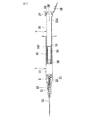
次いで、図17に示すのは本発明の静脈内カテーテル挿入装置の第7の実施形態である。この第7の実施形態は第2の実施形態と類似する構成を有するが、操作端キャップを有しておらず、そしてプランジャ体32の後端開口をユーザが指で自由に塞ぐことができる第2の通気口33として開放し、そしてプランジャ体32の後端開口近くの内周面には、付勢手段4の付勢力により移動して来た収容ユニット34が第2の通気口33から出られないよう、プランジャ体32の内周面から内側に突起して収容ユニット34の移動を阻止できるストッパー327が形成されている。
Next, FIG. 17 shows a seventh embodiment of the intravenous catheter insertion device of the present invention. The seventh embodiment has a configuration similar to that of the second embodiment, but does not have an operation end cap, and the user can freely close the rear end opening of the
次いで、図18に示すのは本発明の静脈内カテーテル挿入装置の第8の実施形態である。この第8の実施形態は第1の実施形態と類似する構成を有するが、第7の実施形態と同じく操作端キャップを有しておらず、そしてプランジャ体32の後端開口をユーザが指で自由に塞ぐことができる第2の通気口33として開放し、そしてプランジャ体32の後端開口の近くには、付勢手段4の付勢力により移動して来た収容ユニット34が第2の通気口33から出られないよう、プランジャ体32の内周面から内側に突起して収容ユニット34の移動を阻止できるストッパー327が形成され、その上第6の実施形態と同じく第2の通気口33を自由に塞ぐことができる取外し可能のカバー38を更に有している。
Next, FIG. 18 shows an eighth embodiment of the intravenous catheter insertion device of the present invention. The eighth embodiment has a configuration similar to that of the first embodiment, but does not have an operation end cap as in the seventh embodiment, and the user opens the rear end opening of the
上記構成によれば、本発明は通常の注射器と同じように針カニューレが患者の血管に進入したかどうかを、血液のバレル内に吸い込まれる勢いで視認して確認することができ、そして使用後にバレル手段外に露出していた針カニューレをバレル手段内に引き込むことによって針カニューレの針先に刺される事故の発生確率を抑えることができる。その上、バレル手段内におけるプランじゃ手段と針カニューレ手段の間に吸い込まれた血液を収容ユニット内に収容すると共に、収容しきれなかった空気を第1の通気口と第2の通気口から排出することができるので、血液が針カニューレの先端開口から射出されて環境を汚染する恐れもなくなるので、実用性が高くて多機能な静脈内カテーテル挿入装置を提供することができる。 According to the above configuration, the present invention can visually check whether the needle cannula has entered the patient's blood vessel in the same manner as a normal syringe with a momentum drawn into the blood barrel, and after use. By pulling the needle cannula exposed outside the barrel means into the barrel means, it is possible to reduce the probability of an accident where the needle tip of the needle cannula is stuck. In addition, the plan in the barrel means accommodates the blood sucked between the means and the needle cannula means in the accommodation unit, and exhausts the air that could not be accommodated from the first and second vents. Therefore, there is no risk of blood being ejected from the tip opening of the needle cannula and contaminating the environment. Therefore, a highly practical and multifunctional intravenous catheter insertion device can be provided.
1 バレル手段
131 バレル手段の後端
132 バレル手段の前端
133 大径部
134 小径部
135 接合部
136 リング溝
137 第2のリング条
138 指当てフランジ
139 段部
141 第1のバレル当接段部
2 針カニューレ手段
21 保持リング
211 第2のリング溝
212 第1のリング溝
221 針座当接段部
222 第1のリング条
223 前接続端部
224 管状部
23 針カニューレ
231 針先端
26 プロテクター
3 プランジャ手段
31 プランジャ手段の管内空間
32 プランジャ体
324 制限リング条
327 ストッパー
33 第2の通気口
34 収容ユニット
341 係合突起
343 後接続端部
344 第1の通気口
35 フィルター
36 シール部材
361 前端面
37 操作端キャップ
38 カバー
4 付勢手段
41 コイルスプリング
411 コイルスプリングの前端
412 コイルスプリングの後端
42 引張りコイルスプリング
421 引張りコイルスプリングの前端
422 引張りコイルスプリングの後端
5 カテーテル手段
51 カテーテルハブ
52 可撓性カテーテル
DESCRIPTION OF
Claims (18)
前端が針先端(231)として鋭く形成された針カニューレ(23)と、略管状に形成されて前記針カニューレを外周より固持し、前記バレル手段に対する更なる前方への移動が所定範囲内に制限されるように、前記バレル手段内の前端近くに配置されている針座(22)と、前記針座を嵌挿させるようにリング状に形成されて前記針座の外周面と前記バレル手段の内周面の間に介在し、前記針座の前記バレル手段に対する更なる後方への移動を制限するように前記針座を保持し、後方からの押圧力を受けて前記バレル手段に対して前方へ押し進まれると、前記針座の前記バレル手段に対する後方への移動を可能にするようになる保持リング(21)と、を備えている針カニューレ手段(2)と、
前記バレル手段の軸線方向に沿って前記バレル手段の大径部内に前後摺動可能に嵌挿し、その前端に開口を有する中空の管状体で、後方から前記バレル手段の後端開口に差し込まれ、前端面が前記保持リングに当接して前記保持リングを前記バレル手段に対して前方へ押し進むことができるプランジャ体(32)と、前記プランジャ体に対する更なる前方への移動が制限されるよう、そして前方からの押圧力を受けて前記プランジャ体に対して後方へ押されると、前記プランジャ体から取り外されるように前記プランジャ体内の前端近くに取り付けられると共に、その前端部が前記プランジャ体のバレル手段に対する相対運動に従って前進して前記針座の後端部に当接して接続できる後接続端部として形成されており、前記後接続端部に設けられて前記プランジャ体の前端開口と連通する開口と、前記プランジャ体の管内空間と連通して気体の行き来だけを許す第1の通気口とを有するように中空の管状体に形成される収容ユニット(34)と、を備えているプランジャ手段と、
前記プランジャ手段のプランジャ体がユーザの操作によって前記バレル手段に対して前進し、前記プランジャ体の前端面が前記保持リングに当接して前記保持リングを前記バレル手段に対して前方へ押し進んで前記針座の前記バレル手段に対する後方へ移動を可能にし、そして前記プランジャ手段が引き続き前進して前記収容ユニットの後接続端部が前記針座の後端部に当接し、そして前記収容ユニットが前方への移動が所定範囲に到達して前進できなくなる前記針座に突き当てられて前記プランジャ体から外されると、前記針座に固定されている前記針カニューレを露出しないように前記バレル手段内に収容するよう、前記収容ユニットと前記針座とを前記プランジャ体の後端へ移動する付勢力を提供する付勢手段とを有していることを特徴とする静脈内カテーテル挿入装置。 A tubular small-diameter portion (134) having an opening at its front end (132) with a predetermined axial direction, and a tubular large-diameter portion with an opening at its rear end (131) in a coaxial line direction ( 133) and tubular barrel means (135) formed between the rear end of the small-diameter portion and the front end of the large-diameter portion and having a joint portion (135) that reduces the diameter from the large-diameter portion to the small-diameter portion. 1) and
A needle cannula (23) whose front end is sharply formed as a needle tip (231) and a substantially tubular shape that holds the needle cannula from the outer periphery, and further forward movement relative to the barrel means is limited within a predetermined range. A needle seat (22) arranged near the front end in the barrel means, and a ring-like shape so as to fit the needle seat, and the outer peripheral surface of the needle seat and the barrel means It is interposed between the inner peripheral surfaces, holds the needle seat so as to limit further rearward movement of the needle seat with respect to the barrel means, and receives a pressing force from the rear to forward the barrel means. A needle cannula means (2) comprising a retaining ring (21) that, when pushed forward, allows the needle seat to move backward relative to the barrel means;
A hollow tubular body that is slidably fitted back and forth in the large-diameter portion of the barrel means along the axial direction of the barrel means, and is inserted into the rear end opening of the barrel means from the rear by a hollow tubular body having an opening at the front end thereof, A plunger body (32) whose front end face abuts on the retaining ring to push the retaining ring forward relative to the barrel means, so that further forward movement relative to the plunger body is restricted, And when it receives a pressing force from the front and is pushed backward with respect to the plunger body, it is attached near the front end in the plunger body so as to be removed from the plunger body, and the front end portion is a barrel means of the plunger body It is formed as a rear connection end portion that can be moved forward according to relative movement with respect to the needle seat and contacted with the rear end portion of the needle seat, and provided at the rear connection end portion. And a housing unit formed in a hollow tubular body so as to have an opening communicating with the front end opening of the plunger body and a first vent opening communicating with a space in the pipe of the plunger body and allowing only gas to flow back and forth. (34) a plunger means comprising:
The plunger body of the plunger means is advanced with respect to the barrel means by a user operation, and the front end surface of the plunger body abuts on the holding ring to push the holding ring forward with respect to the barrel means. Allowing the needle seat to move backward relative to the barrel means, and the plunger means continues to advance so that the rear connecting end of the receiving unit abuts the rear end of the needle seat and the receiving unit moves forward When the movement of the needle reaches the predetermined range and cannot move forward, it is brought into contact with the needle seat and removed from the plunger body, so that the needle cannula fixed to the needle seat is not exposed in the barrel means. And a biasing means for providing a biasing force for moving the storage unit and the needle seat to the rear end of the plunger body so as to be stored. Intravenous catheter insertion device according to.
Priority Applications (1)
| Application Number | Priority Date | Filing Date | Title |
|---|---|---|---|
| JP2007313899A JP2009136397A (en) | 2007-12-04 | 2007-12-04 | Intravenous catheter introducing device |
Applications Claiming Priority (1)
| Application Number | Priority Date | Filing Date | Title |
|---|---|---|---|
| JP2007313899A JP2009136397A (en) | 2007-12-04 | 2007-12-04 | Intravenous catheter introducing device |
Publications (1)
| Publication Number | Publication Date |
|---|---|
| JP2009136397A true JP2009136397A (en) | 2009-06-25 |
Family
ID=40867695
Family Applications (1)
| Application Number | Title | Priority Date | Filing Date |
|---|---|---|---|
| JP2007313899A Pending JP2009136397A (en) | 2007-12-04 | 2007-12-04 | Intravenous catheter introducing device |
Country Status (1)
| Country | Link |
|---|---|
| JP (1) | JP2009136397A (en) |
Cited By (2)
| Publication number | Priority date | Publication date | Assignee | Title |
|---|---|---|---|---|
| WO2015034702A1 (en) * | 2013-09-06 | 2015-03-12 | Millaghi Medical, Inc. | Passive safety i.v. blood collection catheter |
| CN109550103A (en) * | 2019-01-27 | 2019-04-02 | 北京仰生恒泰科技有限责任公司 | A kind of functional intravenous guide tube device blocked |
Citations (4)
| Publication number | Priority date | Publication date | Assignee | Title |
|---|---|---|---|---|
| US5817058A (en) * | 1996-12-23 | 1998-10-06 | Shaw; Thomas J. | Retractable catheter introducer structure |
| JP2005021352A (en) * | 2003-07-01 | 2005-01-27 | Kyo Meisei | Venous catheter insertion instrument |
| JP2005312895A (en) * | 2004-04-30 | 2005-11-10 | Kyo Meisei | Injection syringe |
| JP2006507890A (en) * | 2001-10-26 | 2006-03-09 | リトラクタブル テクノロジーズ,インコーポレイテッド | IV catheter introducer with retractable needle |
-
2007
- 2007-12-04 JP JP2007313899A patent/JP2009136397A/en active Pending
Patent Citations (4)
| Publication number | Priority date | Publication date | Assignee | Title |
|---|---|---|---|---|
| US5817058A (en) * | 1996-12-23 | 1998-10-06 | Shaw; Thomas J. | Retractable catheter introducer structure |
| JP2006507890A (en) * | 2001-10-26 | 2006-03-09 | リトラクタブル テクノロジーズ,インコーポレイテッド | IV catheter introducer with retractable needle |
| JP2005021352A (en) * | 2003-07-01 | 2005-01-27 | Kyo Meisei | Venous catheter insertion instrument |
| JP2005312895A (en) * | 2004-04-30 | 2005-11-10 | Kyo Meisei | Injection syringe |
Cited By (5)
| Publication number | Priority date | Publication date | Assignee | Title |
|---|---|---|---|---|
| WO2015034702A1 (en) * | 2013-09-06 | 2015-03-12 | Millaghi Medical, Inc. | Passive safety i.v. blood collection catheter |
| US9456775B2 (en) | 2013-09-06 | 2016-10-04 | Millaghi Medical, Inc. | Passive safety I.V. blood collection catheter |
| US10758167B2 (en) | 2013-09-06 | 2020-09-01 | Mmi, Llc | Passive safety I.V. blood collection catheter |
| CN109550103A (en) * | 2019-01-27 | 2019-04-02 | 北京仰生恒泰科技有限责任公司 | A kind of functional intravenous guide tube device blocked |
| CN109550103B (en) * | 2019-01-27 | 2024-01-26 | 浙江百获健康科技有限公司 | Vein catheter device capable of plugging |
Similar Documents
| Publication | Publication Date | Title |
|---|---|---|
| JP6571852B2 (en) | Passive safety intravenous blood collection catheter | |
| JP6028021B2 (en) | Catheter assembly | |
| JP4833488B2 (en) | Liquid collection device having a needle stored in an inclined state | |
| US7204813B2 (en) | Cannula retractable medical collection device | |
| US8939938B2 (en) | Needle tip protector | |
| JP6461174B2 (en) | Self-priming system and self-priming method | |
| US6921386B2 (en) | Intravenous catheter inserting device | |
| JP3729736B2 (en) | Self-retracting catheter introducer | |
| CN105102053B (en) | catheter assembly | |
| EP1457229B1 (en) | Intravenous catheter inserting device | |
| US7056306B1 (en) | Fluid sampling device with retractable needle | |
| JP2009136397A (en) | Intravenous catheter introducing device | |
| AU736394B2 (en) | Fluid sampling device with retractable needle | |
| JP2009125312A (en) | Cartridge-type disposable syringe | |
| JP7123359B2 (en) | needle assembly | |
| JP4722365B2 (en) | Safety needle medical device | |
| KR20090059873A (en) | Intravenous catheter insertion apparatus | |
| KR100574070B1 (en) | Intravenous catheter introducing device | |
| JP3882926B2 (en) | Retractable medical blood collection device | |
| JP4359605B2 (en) | Retractable medical blood collection device | |
| JP4359604B2 (en) | Retractable medical blood collection device | |
| EP1570784A1 (en) | Cannula retractable medical collection device | |
| AU2003204253B1 (en) | Intravenous catheter inserting device |
Legal Events
| Date | Code | Title | Description |
|---|---|---|---|
| A977 | Report on retrieval |
Free format text: JAPANESE INTERMEDIATE CODE: A971007 Effective date: 20100701 |
|
| A131 | Notification of reasons for refusal |
Free format text: JAPANESE INTERMEDIATE CODE: A131 Effective date: 20100713 |
|
| A02 | Decision of refusal |
Free format text: JAPANESE INTERMEDIATE CODE: A02 Effective date: 20101207 |