JP2009134777A - Magnetic disk unit and manufacturing method thereof - Google Patents
Magnetic disk unit and manufacturing method thereof Download PDFInfo
- Publication number
- JP2009134777A JP2009134777A JP2007307058A JP2007307058A JP2009134777A JP 2009134777 A JP2009134777 A JP 2009134777A JP 2007307058 A JP2007307058 A JP 2007307058A JP 2007307058 A JP2007307058 A JP 2007307058A JP 2009134777 A JP2009134777 A JP 2009134777A
- Authority
- JP
- Japan
- Prior art keywords
- magnetic disk
- gas
- filter
- gas outlet
- gas inlet
- Prior art date
- Legal status (The legal status is an assumption and is not a legal conclusion. Google has not performed a legal analysis and makes no representation as to the accuracy of the status listed.)
- Pending
Links
- 238000004519 manufacturing process Methods 0.000 title claims abstract description 29
- 239000007789 gas Substances 0.000 claims description 208
- 239000007924 injection Substances 0.000 claims description 32
- 238000002347 injection Methods 0.000 claims description 32
- 238000012360 testing method Methods 0.000 claims description 26
- 239000002245 particle Substances 0.000 claims description 25
- 230000029058 respiratory gaseous exchange Effects 0.000 claims description 25
- 238000000034 method Methods 0.000 claims description 18
- 238000001914 filtration Methods 0.000 claims description 13
- 239000001307 helium Substances 0.000 claims description 4
- 229910052734 helium Inorganic materials 0.000 claims description 4
- SWQJXJOGLNCZEY-UHFFFAOYSA-N helium atom Chemical compound [He] SWQJXJOGLNCZEY-UHFFFAOYSA-N 0.000 claims description 4
- 238000004891 communication Methods 0.000 claims description 3
- 230000000241 respiratory effect Effects 0.000 description 9
- 230000007423 decrease Effects 0.000 description 4
- 230000003749 cleanliness Effects 0.000 description 3
- 239000000126 substance Substances 0.000 description 3
- OKTJSMMVPCPJKN-UHFFFAOYSA-N Carbon Chemical compound [C] OKTJSMMVPCPJKN-UHFFFAOYSA-N 0.000 description 2
- 238000007689 inspection Methods 0.000 description 2
- 239000004745 nonwoven fabric Substances 0.000 description 2
- UFHFLCQGNIYNRP-UHFFFAOYSA-N Hydrogen Chemical compound [H][H] UFHFLCQGNIYNRP-UHFFFAOYSA-N 0.000 description 1
- 230000004075 alteration Effects 0.000 description 1
- 230000015572 biosynthetic process Effects 0.000 description 1
- 239000000428 dust Substances 0.000 description 1
- 239000004519 grease Substances 0.000 description 1
- 239000001257 hydrogen Substances 0.000 description 1
- 229910052739 hydrogen Inorganic materials 0.000 description 1
- 238000005259 measurement Methods 0.000 description 1
- 238000001179 sorption measurement Methods 0.000 description 1
Images


Classifications
-
- G—PHYSICS
- G11—INFORMATION STORAGE
- G11B—INFORMATION STORAGE BASED ON RELATIVE MOVEMENT BETWEEN RECORD CARRIER AND TRANSDUCER
- G11B25/00—Apparatus characterised by the shape of record carrier employed but not specific to the method of recording or reproducing, e.g. dictating apparatus; Combinations of such apparatus
- G11B25/04—Apparatus characterised by the shape of record carrier employed but not specific to the method of recording or reproducing, e.g. dictating apparatus; Combinations of such apparatus using flat record carriers, e.g. disc, card
- G11B25/043—Apparatus characterised by the shape of record carrier employed but not specific to the method of recording or reproducing, e.g. dictating apparatus; Combinations of such apparatus using flat record carriers, e.g. disc, card using rotating discs
-
- G—PHYSICS
- G11—INFORMATION STORAGE
- G11B—INFORMATION STORAGE BASED ON RELATIVE MOVEMENT BETWEEN RECORD CARRIER AND TRANSDUCER
- G11B33/00—Constructional parts, details or accessories not provided for in the other groups of this subclass
- G11B33/14—Reducing influence of physical parameters, e.g. temperature change, moisture, dust
- G11B33/148—Reducing friction, adhesion, drag
-
- G—PHYSICS
- G11—INFORMATION STORAGE
- G11B—INFORMATION STORAGE BASED ON RELATIVE MOVEMENT BETWEEN RECORD CARRIER AND TRANSDUCER
- G11B33/00—Constructional parts, details or accessories not provided for in the other groups of this subclass
- G11B33/14—Reducing influence of physical parameters, e.g. temperature change, moisture, dust
- G11B33/1486—Control/regulation of the pressure, e.g. the pressure inside the housing of a drive
Abstract
Description
本発明は、筐体内に空気よりも密度が低い低密度気体を注入し、磁気ディスクにサーボデータを書き込む、磁気ディスク装置の製造方法に関する。 The present invention relates to a method for manufacturing a magnetic disk device, in which a low-density gas having a lower density than air is injected into a casing and servo data is written to the magnetic disk.
ハードディスクなどの磁気ディスク装置では、磁気ディスクに同心円状に配列する複数のトラックが形成されており、各トラックにはサーボデータが書き込まれている。このサーボデータは、アドレスデータ及びバースト信号を含んでおり、磁気ヘッドの位置制御に利用される。 In a magnetic disk device such as a hard disk, a plurality of tracks arranged concentrically on a magnetic disk are formed, and servo data is written in each track. This servo data includes address data and a burst signal, and is used for position control of the magnetic head.
こうしたサーボデータを書き込む方法の一つとして、磁気ディスク装置を組み立てた後に、筐体内に収納されている磁気ヘッドおよびアクチュエータを制御して、磁気ディスクにサーボデータを書き込む、いわゆるセルフサーボライト(SSW:Self Servo Write)が知られている。
ところで、磁気ディスクにサーボデータを記録する場合、磁気ディスクの回転により生じる空気の流れが磁気ヘッドの支持系を揺らしてしまうため、磁気ディスクに歪んだトラックが形成されてしまうという問題がある。このように歪んだトラックは、磁気ヘッドの位置決めを阻害する要因の一つとなる。 By the way, when servo data is recorded on the magnetic disk, there is a problem that a distorted track is formed on the magnetic disk because the air flow generated by the rotation of the magnetic disk shakes the support system of the magnetic head. Such a distorted track is one of the factors that hinder the positioning of the magnetic head.
そこで、特許文献1には、磁気ディスク装置の筐体に気体注入用の穴を形成し、筐体内にHe(ヘリウム)を注入した状態でセルフサーボライトを行う技術が開示されている。Heは空気よりも密度が低いことから、筐体内をHeで満たすことで磁気ヘッドの揺れを抑制でき、これにより真円に近いトラックを形成することができる。
Therefore,
しかしながら、特許文献1に開示された技術では、気体注入用の穴から筐体内にパーティクル(粒子)が進入してしまうことを防ぐため、Heの注入をクリーンルーム内など空気清浄度が高い環境下で行わなければならず、製造上の制約が大きいという問題がある。
However, in the technique disclosed in
本発明は、上記実情に鑑みて為されたものであり、磁気ディスクにサーボデータを書き込むのに際して、筐体内に低密度気体を簡易に注入することが可能な、磁気ディスク装置の製造方法を提供することをその目的の一つとする。 The present invention has been made in view of the above circumstances, and provides a method of manufacturing a magnetic disk device that can easily inject a low-density gas into a housing when writing servo data on a magnetic disk. One of its purposes is to do.
上記課題を解決するため、本発明の磁気ディスク装置の製造方法は、データを記憶する磁気ディスクと、前記データの書き込み及び読み出しを行う磁気ヘッドと、前記磁気ヘッドを前記磁気ディスクに対して相対的に移動させるアクチュエータと、が密閉された筐体内に収納された磁気ディスク装置の製造方法であって、前記筐体には、該筐体の内部と外部とを連通させるガス注入口およびガス排出口が形成され、該ガス注入口および該ガス排出口のそれぞれにはフィルタが配設されており、前記ガス注入口から前記密閉された筐体内に、空気よりも密度が低い低密度気体を注入し、前記密閉された筐体内に収納されている前記磁気ヘッドおよび前記アクチュエータを制御して、前記磁気ディスクにサーボデータを書き込む、ことを特徴とする。 In order to solve the above problems, a method of manufacturing a magnetic disk apparatus according to the present invention includes a magnetic disk for storing data, a magnetic head for writing and reading data, and a relative position of the magnetic head with respect to the magnetic disk. And a gas inlet and a gas outlet through which the inside and outside of the housing are communicated with each other. Each of the gas inlet and the gas outlet is provided with a filter, and a low-density gas having a density lower than that of air is injected from the gas inlet into the sealed casing. Servo data is written to the magnetic disk by controlling the magnetic head and the actuator housed in the sealed casing. .
本発明の一態様では、前記ガス注入口および前記ガス排出口のそれぞれに配設されたフィルタの少なくとも一方が呼吸フィルタである。 In one aspect of the present invention, at least one of the filters disposed in each of the gas inlet and the gas outlet is a respiratory filter.
本発明の一態様において、前記ガス注入口に配設されたフィルタは、前記ガス排出口に配設されたフィルタよりも気体に含まれる粒子に対する濾過能力が高い。 In one aspect of the present invention, the filter disposed in the gas inlet has a higher filtering ability with respect to particles contained in the gas than the filter disposed in the gas outlet.
また、この態様において、前記ガス注入口に配設されたフィルタを呼吸フィルタとすることができる。 In this aspect, the filter disposed in the gas inlet can be a respiratory filter.
また、この態様において、前記磁気ディスクにサーボデータを書き込んだ後に、前記ガス排出口を閉塞してもよい。 In this aspect, the gas discharge port may be closed after servo data is written to the magnetic disk.
本発明の一態様において、前記ガス排出口に配設されたフィルタは、前記ガス注入口に配設されたフィルタよりも圧力損失が大きい。 In one aspect of the present invention, the filter disposed at the gas outlet has a greater pressure loss than the filter disposed at the gas inlet.
本発明の一態様において、前記ガス排出口は、前記ガス注入口よりも口径が小さい。 In one aspect of the present invention, the gas outlet has a smaller diameter than the gas inlet.
本発明の一態様では、前記密閉された筐体内に前記低密度気体を注入する間、前記磁気ディスクを回転させる。 In one aspect of the present invention, the magnetic disk is rotated while the low-density gas is injected into the sealed casing.
本発明の一態様では、前記低密度気体の注入を開始するまでの間、前記ガス注入口および前記ガス排出口の少なくとも一方を一時的に閉塞する。 In one embodiment of the present invention, at least one of the gas inlet and the gas outlet is temporarily blocked until the low-density gas injection is started.
本発明の一態様では、前記低密度気体の注入を開始する前までに、前記ガス注入口および前記ガス排出口以外の、前記筐体の内部と外部とが連通した隙間を閉塞する。 In one aspect of the present invention, before starting the injection of the low-density gas, a gap between the inside and the outside of the housing other than the gas inlet and the gas outlet is closed.
本発明の一態様では、前記磁気ディスクに前記サーボデータを書き込んでいる間、前記ガス注入口および前記ガス排出口の少なくとも一方を一時的に閉塞する。 In one aspect of the present invention, at least one of the gas inlet and the gas outlet is temporarily blocked while the servo data is being written to the magnetic disk.
また、この態様において、前記ガス注入口に配設されたフィルタは、前記ガス排出口に配設されたフィルタよりも気体に含まれる粒子に対する濾過能力が高く、前記密閉された筐体内に前記低密度気体を注入した後に、前記ガス排出口を先に一時的に閉塞してもよい。 Further, in this aspect, the filter disposed at the gas inlet has a higher filtering ability with respect to particles contained in the gas than the filter disposed at the gas outlet, and the filter is disposed within the sealed casing. After injecting the density gas, the gas outlet may be temporarily closed first.
本発明の一態様では、前記磁気ディスクに前記サーボデータを書き込んだ後に、前記ガス注入口から前記密閉された筐体内に空気を注入する。 In one aspect of the present invention, after the servo data is written to the magnetic disk, air is injected into the sealed casing from the gas inlet.
また、この態様において、前記ガス注入口に配設されたフィルタは、前記ガス排出口に配設されたフィルタよりも気体に含まれる粒子に対する濾過能力が高く、前記密閉された筐体内に前記空気を注入した後に、前記ガス排出口を閉塞してもよい。 Further, in this aspect, the filter disposed at the gas inlet has a higher filtering ability with respect to particles contained in the gas than the filter disposed at the gas outlet, and the air is contained in the sealed casing. After injecting the gas, the gas discharge port may be closed.
本発明の一態様において、前記低密度気体はヘリウムである。 In one aspect of the invention, the low density gas is helium.
次に、本発明の磁気ディスク装置は、データを記憶する磁気ディスクと、前記データの書き込み及び読み出しを行う磁気ヘッドと、前記磁気ヘッドを前記磁気ディスクに対して相対的に移動させるアクチュエータと、が密閉された筐体内に収納された磁気ディスク装置であって、前記筐体には、該筐体の内部と外部とを連通させるガス注入口およびガス排出口が形成されており、前記ガス注入口および前記ガス排出口のそれぞれにはフィルタが配設されている、ことを特徴とする。 Next, the magnetic disk device of the present invention includes a magnetic disk for storing data, a magnetic head for writing and reading the data, and an actuator for moving the magnetic head relative to the magnetic disk. A magnetic disk device housed in a hermetically sealed casing, wherein the casing is formed with a gas inlet and a gas outlet that allow communication between the inside and the outside of the casing. Each of the gas discharge ports is provided with a filter.
本発明の一態様では、前記ガス注入口および前記ガス排出口のそれぞれに配設されたフィルタの少なくとも一方が呼吸フィルタである。 In one aspect of the present invention, at least one of the filters disposed in each of the gas inlet and the gas outlet is a respiratory filter.
本発明の一態様では、前記ガス注入口および前記ガス排出口のうち、一方には呼吸フィルタが配設され、他方は閉塞されている。 In one aspect of the present invention, one of the gas inlet and the gas outlet is provided with a breathing filter and the other is closed.
本発明の一態様では、前記ガス注入口および前記ガス排出口以外の、前記筐体の内部と外部とが連通する隙間が閉塞されている。 In one aspect of the present invention, a gap that communicates the inside and the outside of the housing other than the gas inlet and the gas outlet is closed.
また、本発明の磁気ディスク装置は、データを記憶する磁気ディスクと、前記データの書き込み及び読み出しを行う磁気ヘッドと、前記磁気ヘッドを前記磁気ディスクに対して相対的に移動させるアクチュエータと、が密閉された筐体内に収納された磁気ディスク装置であって、前記筐体には、呼吸フィルタが配設された呼吸口と、フィルタが配設されず且つ閉塞されたパーティクルテスト用のテスト口と、フィルタが配設され且つ閉塞された開口とが形成されている、ことを特徴とする。 In the magnetic disk device of the present invention, a magnetic disk for storing data, a magnetic head for writing and reading the data, and an actuator for moving the magnetic head relative to the magnetic disk are hermetically sealed. A magnetic disk device housed in a housing, wherein the housing has a breathing port provided with a breathing filter, a test port for particle testing in which no filter is placed and closed, An opening in which a filter is disposed and closed is formed.
本発明によれば、筐体に形成されたガス注入口およびガス排出口のそれぞれにフィルタが配設されているので、Heの注入を行う環境の制約が緩和され、筐体内に低密度気体を簡易に注入することができる。 According to the present invention, since the filter is disposed in each of the gas inlet and the gas outlet formed in the casing, the restriction of the environment for injecting He is alleviated, and low density gas is introduced into the casing. Easy injection.
本発明の実施形態について、図面を参照しながら説明する。 Embodiments of the present invention will be described with reference to the drawings.
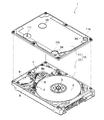
図1に、本発明の一実施形態に係る磁気ディスク装置1の分解斜視図を示す。磁気ディスク装置1の筐体10(DE:Disk Enclosure)は、上方に開口した矩形箱状のベース12と、これを覆う板状のカバー11とで構成されており、ベース12にカバー11が取り付けられることで密閉される。
FIG. 1 is an exploded perspective view of a
筐体10内には、磁気ディスク2及びヘッドアッセンブリ6などが収納されている。磁気ディスク2は、ベース12の底部に設けられたスピンドルモータ3に取り付けられている。この磁気ディスク2には、同心円状に配列する複数のトラック(不図示)が形成されており、各トラックには、所定の周期でサーボデータが書き込まれている。サーボデータは、アドレスデータ及びバースト信号を含む。
The
ヘッドアッセンブリ6は、磁気ディスク2の隣に支承されている。このヘッドアッセンブリ6の先端部には、磁気ヘッド4が支持されている。磁気ヘッド4は、回転する磁気ディスク2上に近接浮上し、データの書き込み及び読み出しを行う。他方、ヘッドアッセンブリ6の後端部には、ボイスコイルモータ7が設けられている。ボイスコイルモータ7は、ヘッドアッセンブリ6を旋回駆動し、磁気ヘッド4を磁気ディスク2の略半径方向に移動させる。
The
また、ヘッドアッセンブリ6には、FPC(Flexible Printed Circuits)8が取り付けられている。このFPC8は、ベース12の底部に設けられたコネクタ9から延出しており、ベース12の裏側に設けられた回路基板(不図示)と、磁気ヘッド4及びボイスコイルモータ7とを電気的に接続する。
Further, an FPC (Flexible Printed Circuits) 8 is attached to the
図2に、筐体10を構成するカバー11の分解斜視図を示す。図2(a)は、カバー11の表面11a側を示し、図2(b)は、カバー11の裏面11b側を示す。
FIG. 2 is an exploded perspective view of the
カバー11には、筐体10の内外を連通させるガス注入口11i、ガス排出口11e、テスト口11t及びネジ穴11sが形成されている。なお、これらガス注入口11i及びガス排出口11eは、ベース12に形成されていてもよい。
The
ガス注入口11iは、いわゆる呼吸口であり、筐体10の内外の気圧差を抑制するために設けられる。また、ガス注入口11iは、後述するように、製造時において筐体10内に気体を充填する際に利用される。
The
このガス注入口11iには、カバー11の裏面11b側に、扁平円柱状の呼吸フィルタ22が配設されている。詳しくは、呼吸フィルタ22は、ガス注入口11iを塞ぐようにカバー11の裏面11bに取り付けられている。この呼吸フィルタ22は、筐体10内に流れ込む気体を濾過して、気体に含まれるパーティクル(粒子)が筐体10内に進入することを抑制する。
A flat cylindrical respiratory filter 22 is disposed on the
また、ガス注入口11iは、カバー11の裏面11b側に取り付けられる呼吸フィルタ22が上記ヘッドアッセンブリ6とコネクタ9との間(図1参照)に収まるような位置に形成されている。
Further, the
ガス排出口11eは、後述するように、製造時において筐体10内に気体を充填する際に利用される。このガス排出口11eには、カバー11の裏面11b側に、不織布からなるシート状のフィルタ24が配設されている。また、ガス排出口11eは、カバー11の表面11a側にリークシール34が貼付されて、閉塞されている。
As will be described later, the
テスト口11tは、後述するように、製造時のテストにおいて利用される。このテスト口11tは、カバー11の表面11a側にリークシール36が貼付されて、閉塞されている。なお、このテスト口11tには、フィルタは配設されていない。
As will be described later, the
ネジ穴11sは、上記ヘッドアッセンブリ6の軸受部6bに締結されるネジが挿通される穴である。このネジ穴11sは、カバー11の表面11a側にリークシール38が貼付されて、閉塞されている。
The
ここで、ガス注入口11iに配設される呼吸フィルタ22は、ガス排出口11eに配設されるフィルタ24よりも、気体に含まれるパーティクルに対する濾過能力が高い。気体に含まれるパーティクルには、塵埃のパーティクルだけでなく、水分のパーティクルや化学物質のパーティクルなど、様々な種類がある。呼吸フィルタ22は、フィルタ24と同様の不織布からなるシート状のフィルタの他に、流路長を確保するための螺旋状の流路部、水分を吸着するための活性炭、及び化学物質を吸着するケミカル吸着フィルタなどを含んでいる。このため、呼吸フィルタ22は、フィルタ24と比して、様々なパーティクルを濾過することができ、こうした濾過を維持できる期間も長いことから、濾過能力が高いということができる。
Here, the respiration filter 22 disposed at the
なお、本実施形態では、ガス排出口11eにシート状のフィルタ24を配設しているが、これに限らず、ガス排出口11eにも呼吸フィルタ22と同様の呼吸フィルタを配設して、ガス排出口11eを呼吸口としてもよい。この場合、ガス排出口11eにリークシール38を貼付せずともよい。
In the present embodiment, the sheet-
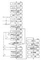
図3に、本発明の一実施形態に係る磁気ディスク装置の製造方法の工程例を示す。この製造方法は、筐体10内にHe(ヘリウム)を充填した状態でセルフサーボライト(SSW:Self Servo Write)を行うことを主な目的としている。
FIG. 3 shows a process example of a method of manufacturing a magnetic disk device according to an embodiment of the present invention. The main purpose of this manufacturing method is to perform self-servo write (SSW) with the
まず、S1ないしS5の工程は、クリーンルーム内で行われる。S1では、呼吸フィルタ22及びフィルタ24をカバー11の裏面11bに貼付する。すなわち、図2(b)に示したように、カバー11の裏面11bに、ガス注入口11iを塞ぐように呼吸フィルタ22を取り付け、ガス排出口11eを塞ぐようにフィルタ24を取り付ける。そして、呼吸フィルタ22及びフィルタ24を取り付けたカバー11を、磁気ディスク2及びヘッドアッセンブリ6等を収納したベース12に取り付けて、筐体10を密閉する。
First, steps S1 to S5 are performed in a clean room. In S <b> 1, the respiratory filter 22 and the
S2では、密閉された筐体10内のパーティクルテストを行う。具体的には、パーティクルの数を検出する検出器をテスト口11tから筐体10内に挿入して測定を行う。なお、テスト口11tには、このように検出器が挿入されることから、ガス注入口11i及びガス排出口11eのようにフィルタを配設することができない。また、テスト口11tは、検出器が挿入されるため、ガス注入口11i及びガス排出口11eと比して口径が大きい。
In S2, a particle test in the sealed
S3では、図4に示すように、テンポラリーシール44を貼付して、ガス排出口11eを一時的に閉塞する。このテンポラリーシール44は、ガス排出口11eを塞ぐ閉塞部44aと、この閉塞部44aから一方向に延出した把手部44bとを有しており、把手部44bがあることによって剥がし易くなっている。
In S3, as shown in FIG. 4, a
このようにテンポラリーシール44を貼付するのは、後述するHe注入工程(S8)が開始されるまでの間に、パーティクルがガス排出口11eからフィルタ24を通過して筐体10内に進入することを極力防ぐためである。なお、フィルタ24の濾過能力が十分であれば、テンポラリーシール44を貼付せずともよい。
The
ここでは、ガス排出口11eに配設されたフィルタ24が、ガス注入口11iに配設された呼吸フィルタ22よりも濾過能力が低いために、ガス排出口11eを閉塞している。また、これに限らず、ガス排出口11eとともにガス注入口11iを一時的に閉塞してもよい。
Here, the
S4では、テスト口11tから空気を注入して、空気リークテストを行う。これにより、筐体10内から空気が漏れ出ないこと、すなわち筐体10が十分に密閉されていることを確認する。
In S4, air is injected from the
ここで、製品としての磁気ディスク装置1では、ガス排出口11eがリークシール34により閉塞されることから(図1参照)、空気リークテストの前にガス排出口11eをテンポラリーシール44により閉塞することで、製品としての磁気ディスク装置1と同じ条件で空気リークテストを行うことができる。
Here, in the
S5では、図5に示すように、リークシール36を貼付してテスト口11tを閉塞する。更には、カバー11に形成されたネジ穴11sをリークシール38により閉塞し、ベース12の裏面側に形成された同様のネジ穴(不図示)もリークシール39により閉塞する。
In S5, as shown in FIG. 5, a
ここで、ネジ穴11sを閉塞するのは、後述するHe注入工程(S8)において筐体10内に注入されたHeが筐体10内から漏れ出ることを抑制するためである。すなわち、前の空気リークテスト(S4)では筐体10内から空気が漏れ出ないことを確認しているが、後の工程S8で注入されるHeは、空気よりも小さく、空気が漏れ出さないような隙間からでも漏れ出す虞がある。このため、本工程では、ネジ穴11s等の、Heが漏れ出す虞がある隙間を閉塞する。他にも、カバー11とベース12とを接合した隙間などを閉塞するようにしてもよい。
Here, the reason why the
なお、テスト口11tは、上記のように筐体10を密閉した後にパーティクルテスト及び空気リークテストに利用されるため、フィルタを配設することができない。このため、本実施形態では、テスト口11tを後述するような気体注入用または気体排出用の開口として用いることはできない。
In addition, since the
以上のS1ないしS5の工程が完了したら、筐体10をクリーンルームから出して、ノーマルエリア(空気清浄度を制御していないエリア)に移す。以降のS6ないしS19の工程は、このノーマルエリアで行われる。
When the above steps S1 to S5 are completed, the
S6では、筐体10内に収納されている磁気ディスク2の全体をACイレースするイレース処理を行う。このイレース処理は、例えば、専用のイレース処理装置により行われる。
In S6, an erase process for AC erasing the entire
S7では、次のHe注入工程(S8)を行うため、ガス排出口11eを閉塞しているテンポラリーシール44(図4参照)を剥がす。ここで、He注入工程(S8)はノーマルエリアで行われるので、Heの注入が開始されるまでの間、ガス排出口11eを一時的に閉塞しておくことで、パーティクルがガス排出口11eからフィルタ24を通過して筐体10内に進入することを極力防ぐことができる。
In S7, in order to perform the next He injection process (S8), the temporary seal 44 (see FIG. 4) closing the
S8では、ガス注入口11i及びガス排出口11eを利用して、密閉された筐体10内にHeを注入する。これは、筐体10内にHeを充填した状態でセルフサーボライトを行うためである。なお、本実施形態では、空気よりも密度が低い低密度気体としてHeを用いているが、これに限らず、水素などを用いてもよい。
In S8, He is injected into the sealed
Heの注入は、例えば、気体注入装置を用いて行うことができる。具体的には、図6に示すように、気体注入装置のノズル50をガス注入口11iに配し、このノズル50からHeを送り込むことで、ガス注入口11iから筐体10内にHeを注入する。そして、筐体10内にHeが注入されると、ガス排出口11eから筐体10内の気体(主に空気)が押し出される。このようにして、筐体10内の空気がHeに置換される。
The injection of He can be performed using a gas injection device, for example. Specifically, as shown in FIG. 6, the
ここで、筐体10のガス注入口11i及びガス排出口11eには、呼吸フィルタ22及びフィルタ24がそれぞれ配設されているので、Heの注入をノーマルエリアで行うことができる。すなわち、Heの注入を、クリーンルームなどの空気清浄度を高めた環境で行わなくてもよいため、製造を簡易化することができる。
Here, since the breathing filter 22 and the
また、ガス注入口11iに配設された呼吸フィルタ22は、ガス排出口11eに配設されたフィルタ24よりも濾過能力が高いため、ガス注入口11iからHeを注入することにより、気体注入装置から送り込まれるHeにパーティクルが含まれる場合であっても、パーティクルが筐体10内に進入することをより効果的に抑制することができる。
In addition, since the breathing filter 22 disposed in the
また、本実施形態では、ガス注入口11iにのみノズル50を配してHeを注入しているが、これに限らず、ガス排出口11eにもノズルを配して、このノズルから筐体10内の気体を吸い出すようにしてもよい。この場合、筐体10内の気圧を制御しやすくなる。また、ガス排出口11eから排出される気体にはHeが含まれるため、排出されるHeを集めて、再利用に供することが好適である。
In this embodiment, the
また、ガス排出口11eに配設されたフィルタ24は、ガス注入口11iに配設された呼吸フィルタ22よりも圧力損失が大きい方が好適である。また、ガス排出口11eは、ガス注入口11iよりも口径が小さい方が好適である。これらの場合、ガス注入口11iよりもガス排出口11eの方が気体が通過し難くなることから、Heを注入する際に筐体10内の気圧を高めることができる。これにより、Heの注入後すぐに筐体10内に空気が流れ込むことを抑制することができ、次の工程(S9,S10)でテンポラリーシール42,44を貼付するまでの時間を確保することができる。
In addition, it is preferable that the
さらに、S8におけるHeの注入は、外部からスピンドルモータ3を駆動して、筐体10内に収納されている磁気ディスク2を回転させながら行われる。これにより、ガス注入口11iから注入したHeを筐体10内で拡散させ易くなり、効率的にHeを充填することができる。
Further, He is injected in S8 while driving the spindle motor 3 from the outside and rotating the
このように磁気ディスク2を回転させながらHeの注入を行う場合、筐体10内の気体が磁気ディスク2の周囲を回転方向に沿って流れるので、ガス注入口11i及びガス排出口11eを、磁気ディスク2の縁に沿って設けることが望ましい。また、ガス注入口11iから注入されたHeを筐体10内で十分に拡散させるため、ガス注入口11i及びガス排出口11eを、磁気ディスク2の回転方向に沿って一定以上離して設けることが望ましい。このため、本実施形態のように、ガス注入口11i及びガス排出口11eを、磁気ディスク2に対して互いに反対側に設けることが好適である。
When He is injected while rotating the
また、磁気ディスク2を回転させながらHeの注入を行う場合、スピンドルモータ3に対して出力される駆動電流の大きさに基づいて、筐体10内のHe濃度を評価することができる。すなわち、筐体10内のHe濃度が増加するのに伴い、回転する磁気ディスク2に働く抵抗の大きさが減少することから、これにより、スピンドルモータ3を所定の回転速度で回転させるために必要となる駆動電流の大きさが減少することになる。このように、スピンドルモータ3に対して出力される駆動電流の大きさは、筐体10内のHe濃度を表す指標ということができる。
When He is injected while rotating the
以上のHe注入工程(S8)が終了したら、セルフサーボライト(S12)を開始する前に、図7に示すように、テンポラリーシール42,44を貼付して、ガス注入口11i及びガス排出口11eを一時的に閉塞する(S9,S10)。これは、セルフサーボライト(S12)が行われている間に筐体10内からHeが漏れ出ることを抑制するためである。
When the above He injection step (S8) is completed, before starting the self-servo write (S12), as shown in FIG. 7, the
また、ガス排出口11eを閉塞するテンポラリーシール44は、ガス注入口11iを閉塞するテンポラリーシール42よりも先に貼付される(すなわち、Tb<Ta)。これは、ガス排出口11eに配設されたフィルタ24が、ガス注入口11iに配設された呼吸フィルタ22よりも漏洩抵抗が低いためである。
Further, the
また、筐体10内にHeを注入後、ガス注入口11i及びガス排出口11eを閉塞しない場合に筐体10内のHe濃度が低下して許容範囲を下回ってしまうまでの時間を、規定時間Teとするとき、筐体10内にHeを注入後、テンポラリーシール42,44が貼付されるまでの時間(Ta,Tb)が規定時間Teを越えないようにする。この規定時間Teを超えた場合には、S8に戻り、再度Heを注入する(S11)。
In addition, after He is injected into the
S12では、密閉された筐体10内に収納されている磁気ヘッド4及びボイスコイルモータ7を外部から制御して、磁気ディスク2にサーボデータを書き込む、いわゆるセルフサーボライト(SSW)を行う。
In S12, the magnetic head 4 and the
これら磁気ヘッド4及びボイスコイルモータ7の制御は、外部のサーボデータ記録装置により、筐体10内のコネクタ9及びFPC8を介して行われる。具体的には、サーボデータ記録装置は、磁気ディスク2に書き込むべきサーボデータを磁気ヘッド4に出力する。また、磁気ヘッド4が磁気ディスク2から読み出したサーボデータを取得する。更に、取得したサーボデータに応じてボイスコイルモータ7の駆動信号を生成し、出力する。
The magnetic head 4 and the
また、サーボデータの書き込みは、磁気ヘッド4に含まれる記録素子と再生素子とが磁気ディスク2の径方向にずれていることを利用し、既に形成されたトラックに磁気ヘッド4を追従させた状態でサーボデータを書き込むことにより、新たなトラックを形成する。すなわち、既に形成されたトラックから再生素子によりサーボデータを読み出し、読み出したサーボデータに基づいて磁気ヘッド4をトラックに追従させる。そして、この状態で、記録素子によりサーボデータを書き込むことで新たなトラックを形成する。そして、こうしたトラックの形成を、磁気ディスク2の半径方向に進めていく。
The servo data is written using the fact that the recording element and the reproducing element included in the magnetic head 4 are displaced in the radial direction of the
ここで、筐体10内には上記He注入工程(S8)によりHeが充填されているので、磁気ディスク2に歪みの少ない真円に近いトラックを形成することができる。
Here, since the
また、筐体10のガス注入口11i及びガス排出口11eには、呼吸フィルタ22及びフィルタ24が配設され、更にはテンポラリーシール42,44がそれぞれ貼付されているので、筐体10内からのHeの漏れ出しを抑制でき、この結果、筐体10をノーマルエリアに配置した状態でセルフサーボライトを行うことができる。
In addition, since the breathing filter 22 and the
また、上述したようにHe注入工程(S8)もノーマルエリアで行われるので、Heの注入後からセルフサーボライトを開始するまでの時間を短縮することができ、この結果、筐体10内のHe濃度が高水準に維持されているうちにセルフサーボライトを行うことができる。
Further, as described above, since the He injection step (S8) is also performed in the normal area, it is possible to shorten the time from the start of He injection to the start of self-servo write. As a result, the He in the
また、筐体10内にHeを注入後、ガス注入口11i及びガス排出口11eを閉塞した場合に筐体10内のHe濃度が低下して許容範囲を下回ってしまうまでの時間を、規定時間Tfとするとき、筐体10内にHeを注入後、セルフサーボライトが終了するまでの時間(Tc+Td)が規定時間Tfを越えないようにする。
Further, after He is injected into the
以上のセルフサーボライト(S12)が終了したら、ガス注入口11i及びガス排出口11eを閉塞しているテンポラリーシール42,44を剥がす(S13,S14)。
When the above self-servo light (S12) is completed, the
また、筐体10内にHeを注入後、筐体10内からHeが漏れ出して部品に変化が現れるまでの時間を、規定時間Thとするとき、筐体10内にHeを注入後、セルフサーボライトが終了し、テンポラリーシール42,44を剥がすまでの時間(Tc+Td+Tg)が規定時間Thを越えないようにする。筐体10内からHeが漏れ出すことによる部品の変化は、例えば、筐体10内の気圧の低下によるカバー11の変形や、摺動部分に付されたグリースの変質などがある。
Moreover, after injection of He in the
S15では、ガス注入口11i及びガス排出口11eを利用して、密閉された筐体10内に空気を注入する。このS15は、上記S8と同様に行うことができる。このようにセルフサーボライト(S12)後に筐体10内に空気を充填するのは、後の前工程検査(S18)及びテスト工程(S19)を、製品としての磁気ディスク装置1と同じ条件で行うためである。
In S15, air is injected into the sealed
また、ガス注入口11iから筐体10内に空気を注入する際、ガス排出口11eから筐体10外へHeが排出されるため、ガス排出口11eから排出されるHeを集めて、再利用に供することが好適である。
Further, when air is injected into the
S16では、図8に示すように、リークシール34を貼付して、ガス排出口11eを閉塞する。これにより、製品としての磁気ディスク装置1において、パーティクルがガス排出口11eから筐体10内に進入することを防ぐことができる。ここでは、ガス排出口11eに配設されたフィルタ24が、ガス注入口11iに配設された呼吸フィルタ22よりも濾過能力が低いために、ガス排出口11eを閉塞している。
In S16, as shown in FIG. 8, the
その後、筐体10の裏側に回路基板を取り付け(S17)、所定の前工程検査(S18)及びテスト工程(S19)を行う。以上の工程により、磁気ディスク装置1が完成する。
Thereafter, a circuit board is attached to the back side of the housing 10 (S17), and predetermined pre-process inspection (S18) and test process (S19) are performed. The
1 磁気ディスク装置、2 磁気ディスク、3 スピンドルモータ、4 磁気ヘッド、6 ヘッドアッセンブリ、7 ボイスコイルモータ、8 FPC、9 コネクタ、10 筐体、11 カバー、11i ガス注入口(呼吸口)、11e ガス排出口、11t テスト口、11s ネジ穴、12 ベース、22 呼吸フィルタ、24 フィルタ、34,36,38,39 リークシール、42,44 テンポラリーシール、50 ノズル。
DESCRIPTION OF
Claims (20)
前記筐体には、該筐体の内部と外部とを連通させるガス注入口およびガス排出口が形成され、該ガス注入口および該ガス排出口のそれぞれにはフィルタが配設されており、
前記ガス注入口から前記密閉された筐体内に、空気よりも密度が低い低密度気体を注入し、
前記密閉された筐体内に収納されている前記磁気ヘッドおよび前記アクチュエータを制御して、前記磁気ディスクにサーボデータを書き込む、
磁気ディスク装置の製造方法。 A magnetic disk in which a magnetic disk for storing data, a magnetic head for writing and reading the data, and an actuator for moving the magnetic head relative to the magnetic disk are housed in a sealed housing A device manufacturing method comprising:
The casing is formed with a gas inlet and a gas outlet that allow communication between the inside and the outside of the casing, and a filter is disposed in each of the gas inlet and the gas outlet,
Injecting a low density gas having a lower density than air into the sealed casing from the gas inlet,
Controlling the magnetic head and the actuator housed in the sealed casing to write servo data to the magnetic disk;
A method of manufacturing a magnetic disk device.
請求項1に記載の磁気ディスク装置の製造方法。 At least one of the filters disposed in each of the gas inlet and the gas outlet is a breathing filter,
The method of manufacturing a magnetic disk device according to claim 1.
請求項1に記載の磁気ディスク装置の製造方法。 The filter disposed at the gas inlet has a higher filtering capacity for particles contained in the gas than the filter disposed at the gas outlet.
The method of manufacturing a magnetic disk device according to claim 1.
請求項3に記載の磁気ディスク装置の製造方法。 The filter disposed at the gas inlet is a breathing filter,
The method for manufacturing a magnetic disk device according to claim 3.
請求項3に記載の磁気ディスク装置の製造方法。 After writing servo data on the magnetic disk, the gas outlet is closed.
The method for manufacturing a magnetic disk device according to claim 3.
請求項1に記載の磁気ディスク装置の製造方法。 The filter disposed at the gas outlet has a greater pressure loss than the filter disposed at the gas inlet.
The method of manufacturing a magnetic disk device according to claim 1.
請求項1に記載の磁気ディスク装置の製造方法。 The gas outlet has a smaller diameter than the gas inlet,
The method of manufacturing a magnetic disk device according to claim 1.
請求項1に記載の磁気ディスク装置の製造方法。 Rotating the magnetic disk while injecting the low density gas into the sealed casing;
The method of manufacturing a magnetic disk device according to claim 1.
請求項1に記載の磁気ディスク装置の製造方法。 Until the injection of the low-density gas is started, at least one of the gas inlet and the gas outlet is temporarily blocked.
The method of manufacturing a magnetic disk device according to claim 1.
請求項1に記載の磁気ディスク装置の製造方法。 Before starting the injection of the low-density gas, the gap between the inside and the outside of the housing other than the gas inlet and the gas outlet is closed.
The method of manufacturing a magnetic disk device according to claim 1.
請求項1に記載の磁気ディスク装置の製造方法。 Temporarily writing at least one of the gas inlet and the gas outlet while writing the servo data to the magnetic disk;
The method of manufacturing a magnetic disk device according to claim 1.
前記密閉された筐体内に前記低密度気体を注入した後に、前記ガス排出口を先に一時的に閉塞する、
請求項11に記載の磁気ディスク装置の製造方法。 The filter disposed at the gas inlet has a higher filtering ability for particles contained in the gas than the filter disposed at the gas outlet,
After injecting the low density gas into the sealed casing, the gas outlet is temporarily closed first.
The method of manufacturing a magnetic disk device according to claim 11.
請求項1に記載の磁気ディスク装置の製造方法。 After writing the servo data to the magnetic disk, air is injected into the sealed casing from the gas inlet.
The method of manufacturing a magnetic disk device according to claim 1.
前記密閉された筐体内に前記空気を注入した後に、前記ガス排出口を閉塞する、
請求項13に記載の磁気ディスク装置の製造方法。 The filter disposed at the gas inlet has a higher filtering ability for particles contained in the gas than the filter disposed at the gas outlet,
After injecting the air into the sealed casing, the gas outlet is closed.
A method of manufacturing a magnetic disk device according to claim 13.
請求項1に記載の磁気ディスク装置の製造方法。 The low density gas is helium;
The method of manufacturing a magnetic disk device according to claim 1.
前記筐体には、該筐体の内部と外部とを連通させるガス注入口およびガス排出口が形成されており、
前記ガス注入口および前記ガス排出口のそれぞれにはフィルタが配設されている、
磁気ディスク装置。 A magnetic disk in which a magnetic disk for storing data, a magnetic head for writing and reading the data, and an actuator for moving the magnetic head relative to the magnetic disk are housed in a sealed housing A device,
The casing is formed with a gas inlet and a gas outlet that allow communication between the inside and outside of the casing.
Each of the gas inlet and the gas outlet is provided with a filter.
Magnetic disk unit.
請求項16に記載の磁気ディスク装置。 At least one of the filters disposed in each of the gas inlet and the gas outlet is a breathing filter,
The magnetic disk device according to claim 16.
請求項16に記載の磁気ディスク装置。 One of the gas inlet and the gas outlet is provided with a breathing filter and the other is closed.
The magnetic disk device according to claim 16.
請求項16に記載の磁気ディスク装置。 Except for the gas inlet and the gas outlet, a gap communicating between the inside and the outside of the housing is closed.
The magnetic disk device according to claim 16.
前記筐体には、呼吸フィルタが配設された呼吸口と、フィルタが配設されず且つ閉塞されたパーティクルテスト用のテスト口と、フィルタが配設され且つ閉塞された開口とが形成されている、
磁気ディスク装置。 A magnetic disk in which a magnetic disk for storing data, a magnetic head for writing and reading the data, and an actuator for moving the magnetic head relative to the magnetic disk are housed in a sealed housing A device,
The casing is formed with a breathing port in which a breathing filter is disposed, a test port for particle testing in which no filter is disposed and closed, and an opening in which a filter is disposed and closed. Yes,
Magnetic disk unit.
Priority Applications (2)
| Application Number | Priority Date | Filing Date | Title |
|---|---|---|---|
| JP2007307058A JP2009134777A (en) | 2007-11-28 | 2007-11-28 | Magnetic disk unit and manufacturing method thereof |
| US12/290,361 US7852595B2 (en) | 2007-11-28 | 2008-10-29 | Magnetic disk unit and manufacturing method thereof |
Applications Claiming Priority (1)
| Application Number | Priority Date | Filing Date | Title |
|---|---|---|---|
| JP2007307058A JP2009134777A (en) | 2007-11-28 | 2007-11-28 | Magnetic disk unit and manufacturing method thereof |
Publications (2)
| Publication Number | Publication Date |
|---|---|
| JP2009134777A true JP2009134777A (en) | 2009-06-18 |
| JP2009134777A5 JP2009134777A5 (en) | 2010-11-25 |
Family
ID=40669489
Family Applications (1)
| Application Number | Title | Priority Date | Filing Date |
|---|---|---|---|
| JP2007307058A Pending JP2009134777A (en) | 2007-11-28 | 2007-11-28 | Magnetic disk unit and manufacturing method thereof |
Country Status (2)
| Country | Link |
|---|---|
| US (1) | US7852595B2 (en) |
| JP (1) | JP2009134777A (en) |
Cited By (1)
| Publication number | Priority date | Publication date | Assignee | Title |
|---|---|---|---|---|
| JP2011248962A (en) * | 2010-05-27 | 2011-12-08 | Kuroda Techno Co Ltd | Magnetic disk device assembling apparatus, and magnetic disk device assembling method |
Families Citing this family (3)
| Publication number | Priority date | Publication date | Assignee | Title |
|---|---|---|---|---|
| JP5124248B2 (en) * | 2007-11-28 | 2013-01-23 | エイチジーエスティーネザーランドビーブイ | Manufacturing method of magnetic disk drive |
| US8085488B2 (en) * | 2009-08-27 | 2011-12-27 | Hitachi Global Storage Technologies Netherlands B.V. | Predicting operational problems in a hard-disk drive (HDD) |
| JP2011090747A (en) * | 2009-10-23 | 2011-05-06 | Hitachi Global Storage Technologies Netherlands Bv | Manufacturing method of magnetic disk device |
Citations (10)
| Publication number | Priority date | Publication date | Assignee | Title |
|---|---|---|---|---|
| JPS5548877A (en) * | 1978-10-02 | 1980-04-08 | Nippon Telegr & Teleph Corp <Ntt> | Magnetic memory unit |
| JPS62279591A (en) * | 1986-05-28 | 1987-12-04 | Hitachi Ltd | Hermetically sealed type magnetic disk device |
| JPH052864A (en) * | 1991-06-25 | 1993-01-08 | Hitachi Ltd | Magnetic disk device |
| JPH07235175A (en) * | 1994-02-22 | 1995-09-05 | Hitachi Ltd | Magnetic disk apparatus and driving method therefor |
| JP2000021745A (en) * | 1998-06-30 | 2000-01-21 | Canon Inc | Aligner |
| JP2006040423A (en) * | 2004-07-28 | 2006-02-09 | Hitachi Global Storage Technologies Netherlands Bv | Disk device and its manufacturing method |
| JP2006120383A (en) * | 2004-10-20 | 2006-05-11 | Equos Research Co Ltd | Fuel cell system and fuel gas supplying method |
| JP2006127674A (en) * | 2004-10-29 | 2006-05-18 | Toshiba Corp | Disk apparatus |
| JP2006294159A (en) * | 2005-04-13 | 2006-10-26 | Matsushita Electric Ind Co Ltd | Dew condensation preventing device for hard disk drive |
| JP2007012150A (en) * | 2005-06-29 | 2007-01-18 | Toshiba Corp | Disk device |
Family Cites Families (11)
| Publication number | Priority date | Publication date | Assignee | Title |
|---|---|---|---|---|
| US4307425A (en) * | 1978-10-02 | 1981-12-22 | Nippon Telegraph & Telephone Public Corporation | Breathing device for a closed housing of a magnetic memory device |
| JP2002245771A (en) * | 2001-02-13 | 2002-08-30 | Internatl Business Mach Corp <Ibm> | Disk driver, hard disk drive, cover, base and method of inspecting disk driver |
| SG103906A1 (en) | 2002-03-13 | 2004-05-26 | Toshiba Kk | Method and apparatus for head positioning control in a disk drive |
| US6898043B2 (en) * | 2002-05-20 | 2005-05-24 | Seagate Technology Llc | Dual stage enclosure for servo track writer utilizing low-density gas |
| JP2003346439A (en) | 2002-05-29 | 2003-12-05 | Internatl Business Mach Corp <Ibm> | Data storage device, controller, off-track control method and control method |
| US6999262B2 (en) * | 2003-12-10 | 2006-02-14 | Samsung Electronics Co., Ltd. | Servo track writing for ultra-high TPI disk drive in low density medium condition |
| JP2006221733A (en) | 2005-02-10 | 2006-08-24 | Hitachi Global Storage Technologies Netherlands Bv | Data storage device and its control method |
| US7375916B2 (en) | 2006-03-17 | 2008-05-20 | Hitachi Global Storage Technologies Netherlands B.V. | Magnetic recording disk drive with multiple feedforward controllers for rotational vibration cancellation |
| JP2006221806A (en) | 2006-04-10 | 2006-08-24 | Fujitsu Ltd | Method for controlling magnetic disk device, and disk device |
| JP2008310891A (en) * | 2007-06-15 | 2008-12-25 | Hitachi Global Storage Technologies Netherlands Bv | Disk drive device and its manufacturing method |
| JP5124248B2 (en) * | 2007-11-28 | 2013-01-23 | エイチジーエスティーネザーランドビーブイ | Manufacturing method of magnetic disk drive |
-
2007
- 2007-11-28 JP JP2007307058A patent/JP2009134777A/en active Pending
-
2008
- 2008-10-29 US US12/290,361 patent/US7852595B2/en active Active
Patent Citations (10)
| Publication number | Priority date | Publication date | Assignee | Title |
|---|---|---|---|---|
| JPS5548877A (en) * | 1978-10-02 | 1980-04-08 | Nippon Telegr & Teleph Corp <Ntt> | Magnetic memory unit |
| JPS62279591A (en) * | 1986-05-28 | 1987-12-04 | Hitachi Ltd | Hermetically sealed type magnetic disk device |
| JPH052864A (en) * | 1991-06-25 | 1993-01-08 | Hitachi Ltd | Magnetic disk device |
| JPH07235175A (en) * | 1994-02-22 | 1995-09-05 | Hitachi Ltd | Magnetic disk apparatus and driving method therefor |
| JP2000021745A (en) * | 1998-06-30 | 2000-01-21 | Canon Inc | Aligner |
| JP2006040423A (en) * | 2004-07-28 | 2006-02-09 | Hitachi Global Storage Technologies Netherlands Bv | Disk device and its manufacturing method |
| JP2006120383A (en) * | 2004-10-20 | 2006-05-11 | Equos Research Co Ltd | Fuel cell system and fuel gas supplying method |
| JP2006127674A (en) * | 2004-10-29 | 2006-05-18 | Toshiba Corp | Disk apparatus |
| JP2006294159A (en) * | 2005-04-13 | 2006-10-26 | Matsushita Electric Ind Co Ltd | Dew condensation preventing device for hard disk drive |
| JP2007012150A (en) * | 2005-06-29 | 2007-01-18 | Toshiba Corp | Disk device |
Cited By (1)
| Publication number | Priority date | Publication date | Assignee | Title |
|---|---|---|---|---|
| JP2011248962A (en) * | 2010-05-27 | 2011-12-08 | Kuroda Techno Co Ltd | Magnetic disk device assembling apparatus, and magnetic disk device assembling method |
Also Published As
| Publication number | Publication date |
|---|---|
| US7852595B2 (en) | 2010-12-14 |
| US20090135517A1 (en) | 2009-05-28 |
Similar Documents
| Publication | Publication Date | Title |
|---|---|---|
| JP5124248B2 (en) | Manufacturing method of magnetic disk drive | |
| US5447695A (en) | Chemical breather filter assembly | |
| CN103050143B (en) | Hard disk drive | |
| US7130149B2 (en) | Fluid-borne contaminant protection using a filter assembly with a leading edge guide surface | |
| US8885289B2 (en) | Magnetic storage device with multi-functional component for controlling chemical and water vapor therein | |
| US9466335B2 (en) | Hermetic hard disk drives comprising integrally molded filters and related methods | |
| US8867164B2 (en) | Magnetic storage device with humidity control device incorporating a differentially permeable membrane | |
| JP2005507540A (en) | Disk drive servo track writer using low density gas | |
| KR100530308B1 (en) | An improved ventilation path for a disk drive apparatus | |
| US8693135B2 (en) | Magnetic storage device with means for supplying a beneficial vapor via a desiccant device | |
| US8861127B2 (en) | Magnetic storage device with dynamic humidity control system to mitigate water vapor transients | |
| JP2009134777A (en) | Magnetic disk unit and manufacturing method thereof | |
| JP2011008841A (en) | Disk device and aspiration filter using therefor | |
| JP2011090747A (en) | Manufacturing method of magnetic disk device | |
| US20030218829A1 (en) | Fluid-borne contaminant protection using a filter assembly with a leading edge guide surface | |
| JP3617959B2 (en) | Magnetic disk unit | |
| JP2004022011A (en) | Magnetic disk cartridge | |
| JP2006127674A (en) | Disk apparatus | |
| JP2007066508A (en) | Particle extracting device of hard disk drive and hard disk drive including the same | |
| JP2011118979A (en) | Method of manufacturing magnetic disk device | |
| US20240144979A1 (en) | Hard disk drive breather filter enabling sorbent replacement | |
| JP2024063753A (en) | Hard disk drive breather filters that allow for sorbent replacement | |
| JPH05198155A (en) | Optical disk device | |
| JP2008034066A (en) | Disk device | |
| JP2004158137A (en) | Cleaning device of magnetic disk |
Legal Events
| Date | Code | Title | Description |
|---|---|---|---|
| A521 | Request for written amendment filed |
Free format text: JAPANESE INTERMEDIATE CODE: A523 Effective date: 20101008 |
|
| A621 | Written request for application examination |
Free format text: JAPANESE INTERMEDIATE CODE: A621 Effective date: 20101008 |
|
| A977 | Report on retrieval |
Free format text: JAPANESE INTERMEDIATE CODE: A971007 Effective date: 20110721 |
|
| A131 | Notification of reasons for refusal |
Free format text: JAPANESE INTERMEDIATE CODE: A131 Effective date: 20110726 |
|
| A521 | Request for written amendment filed |
Free format text: JAPANESE INTERMEDIATE CODE: A523 Effective date: 20111003 |
|
| A02 | Decision of refusal |
Free format text: JAPANESE INTERMEDIATE CODE: A02 Effective date: 20120403 |