JP2009130539A - Image pickup apparatus and display controlling method therefor - Google Patents
Image pickup apparatus and display controlling method therefor Download PDFInfo
- Publication number
- JP2009130539A JP2009130539A JP2007302127A JP2007302127A JP2009130539A JP 2009130539 A JP2009130539 A JP 2009130539A JP 2007302127 A JP2007302127 A JP 2007302127A JP 2007302127 A JP2007302127 A JP 2007302127A JP 2009130539 A JP2009130539 A JP 2009130539A
- Authority
- JP
- Japan
- Prior art keywords
- display
- video light
- light mode
- video
- white
- Prior art date
- Legal status (The legal status is an assumption and is not a legal conclusion. Google has not performed a legal analysis and makes no representation as to the accuracy of the status listed.)
- Pending
Links
Images


Abstract
Description
本発明は、被写体を撮像する撮像装置及びその表示制御方法に関する。 The present invention relates to an imaging apparatus that images a subject and a display control method thereof.
従来、撮像装置である各種カメラにおいて、被写体に対する照明光源として、内蔵ライトや、カメラ本体に対して着脱自在に設けられた外付けライトである外部照明等が一般的に用いられている。また、液晶パネルを全白にしてその光を被写体に向けることで、ビデオライトとして使用することが知られている(特許文献1参照)。 2. Description of the Related Art Conventionally, in various cameras that are imaging devices, a built-in light, an external light that is an external light provided detachably with respect to a camera body, or the like is generally used as an illumination light source for a subject. In addition, it is known that the liquid crystal panel is used as a video light by making the liquid crystal panel completely white and directing the light toward the subject (see Patent Document 1).
また、ビデオライトモード検出回路から制御マイコンにビデオライトモードのON信号を入力することにより、LCDパネルを全白表示に切り替えてビデオライトとして利用するビデオカメラが提案されている。
しかしながら、上記従来の撮像装置では、ビデオライトモード検出回路でビデオライトモードのONが検出されると、LCDパネルが全白表示になるので、ビデオライトモードの解除方法が分りにくかった。特に、誤操作によりビデオライトモードに移行した場合、故障と勘違いしてしまいかねなかった。 However, in the conventional imaging apparatus, when the video light mode detection circuit detects that the video light mode is ON, the LCD panel is displayed in all white, so that the method for canceling the video light mode is difficult to understand. In particular, when switching to the video light mode due to an erroneous operation, it could be mistaken for a failure.
そこで、本発明は、上記問題点に鑑みなされたものであり、使用者がビデオライトモードの解除方法を容易に理解することができる撮像装置及びその表示制御方法を提供することを目的とする。 Therefore, the present invention has been made in view of the above problems, and an object of the present invention is to provide an imaging apparatus and a display control method thereof that allow a user to easily understand a video light mode canceling method.
上記目的を達成するために、本発明の撮像装置は、被写体を撮像する撮像装置であって、前記撮像された被写体の映像表示あるいは全白表示を行う表示手段と、前記表示手段をビデオライトとして使用するためのビデオライトモードを選択する選択手段と、前記ビデオライトモードが選択されている時、特定の状況が発生した場合、前記ビデオライトモードを解除して前記表示手段による全白表示を終了させる表示制御手段とを備えたことを特徴とする。 In order to achieve the above object, an imaging apparatus according to the present invention is an imaging apparatus for imaging a subject, wherein display means for displaying an image or all white of the captured subject, and the display means as a video light. Selection means for selecting a video light mode to use, and when the video light mode is selected, if a specific situation occurs, the video light mode is canceled and all white display by the display means is terminated. The display control means is provided.
本発明の撮像装置は、被写体を撮像する撮像装置であって、前記撮像された被写体の映像表示あるいは全白表示を行う表示手段と、前記表示手段の開閉状態を検出する開閉検出手段と、前記表示手段をビデオライトとして使用するためのビデオライトモードを選択する選択手段と、前記ビデオライトモードが選択されている時、前記開閉検出手段によって前記表示手段が開状態であることが検出された場合、前記表示手段を全白表示に切り替え、一方、前記表示手段が閉状態であることが検出された場合、前記ビデオライトモードを解除して前記表示手段による全白表示を終了させる表示制御手段とを備えたことを特徴とする。 The imaging device of the present invention is an imaging device for imaging a subject, wherein display means for displaying an image or all white display of the captured subject, opening / closing detection means for detecting an open / closed state of the display means, Selection means for selecting a video light mode for using the display means as a video light, and when the video light mode is selected, the open / close detection means detects that the display means is in an open state A display control means for switching the display means to all white display, and on the other hand, canceling the video light mode and ending the all white display by the display means when it is detected that the display means is closed. It is provided with.
本発明の撮像装置は、被写体を撮像する撮像装置であって、前記撮像された被写体の映像表示あるいは全白表示を行う表示手段と、前記撮像装置に対してキー操作が行われたことを検出する操作検出手段と、最後に前記キー操作が行われたことが検出されてからの時間を計時する計時手段と、前記表示手段をビデオライトとして使用するためのビデオライトモードを選択する選択手段と、前記ビデオライトモードが選択されている時、前記表示手段を全白表示に切り替え、一方、前記計時手段によって計時された時間が所定時間を経過した場合、前記ビデオライトモードを解除して前記表示手段による全白表示を終了させる表示制御手段とを備えたことを特徴とする。 An imaging apparatus according to the present invention is an imaging apparatus that captures an image of a subject, the display means for performing video display or all-white display of the captured subject, and detecting that a key operation has been performed on the imaging device. An operation detecting means for measuring, a time measuring means for measuring time since it was detected that the key operation was last performed, and a selecting means for selecting a video light mode for using the display means as a video light. When the video light mode is selected, the display means is switched to all white display. On the other hand, when the time counted by the time measuring means has passed a predetermined time, the video light mode is canceled and the display is performed. And display control means for ending the all white display by the means.
本発明の撮像装置は、被写体を撮像する撮像装置であって、前記撮像された被写体の映像表示あるいは全白表示を行う表示手段と、前記撮像装置に着脱自在に設けられ、前記撮像された映像が記録される記録媒体と、前記記録媒体を外部に取り出すための取出し操作が行われたことを検出する取出検出手段と、前記表示手段をビデオライトとして使用するためのビデオライトモードを選択する選択手段と、前記ビデオライトモードが選択されている時、前記表示手段を全白表示に切り替え、一方、前記取出し操作が行われたことが検出された場合、前記ビデオライトモードを解除して前記表示手段による全白表示を終了させる表示制御手段とを備えたことを特徴とする。 An imaging apparatus according to the present invention is an imaging apparatus that captures an image of a subject, the display means for displaying an image of the captured subject or a white display, and the image capturing device that is detachably provided on the imaging device. A recording medium on which the recording medium is recorded, an extraction detecting means for detecting that an extraction operation for taking out the recording medium to the outside has been performed, and a selection for selecting a video light mode for using the display means as a video light And when the video light mode is selected, the display means is switched to all white display, while if it is detected that the take-out operation has been performed, the video light mode is canceled and the display is performed. And display control means for ending the all white display by the means.
本発明の撮像装置は、被写体を撮像する撮像装置であって、前記撮像された被写体の映像表示あるいは全白表示を行う表示手段と、前記撮像装置に設けられ、前記撮像された映像が記録される記録媒体と、前記記録媒体の残容量を検出する残容量検出手段と、前記表示手段をビデオライトとして使用するためのビデオライトモードを選択する選択手段と、前記ビデオライトモードが選択されている時、前記表示手段を全白表示に切り替え、一方、前記残容量検出手段によって前記記録媒体の残容量が閾値以下となった場合、前記ビデオライトモードを解除して前記表示手段による全白表示を終了させる表示制御手段とを備えたことを特徴とする。 An imaging apparatus according to the present invention is an imaging apparatus that captures an image of a subject, and is provided with display means for displaying an image of the imaged subject or an all-white display; and the imaging device records the captured image. A recording medium, a remaining capacity detecting means for detecting a remaining capacity of the recording medium, a selecting means for selecting a video light mode for using the display means as a video light, and the video light mode is selected. When the display means switches to all white display, and when the remaining capacity of the recording medium falls below a threshold by the remaining capacity detection means, the video light mode is canceled and the display means displays all white. And display control means for ending.
本発明の撮像装置は、被写体を撮像する撮像装置であって、前記撮像された被写体の映像表示あるいは全白表示を行う表示手段と、前記表示手段をビデオライトとして使用するためのビデオライトモードを選択する選択手段と、前記ビデオライトモードが選択されている時、前記表示手段を全白表示に切り替える表示制御手段と、前記切り替えられた全白表示に前記ビデオライトモードの解除方法を示す内容を重畳する重畳手段と、前記重畳されたビデオライトモードの解除方法を示す内容に従って、所定の操作が行われた場合、前記ビデオライトモードを解除して前記表示手段による全白表示を終了させる表示制御手段とを備えたことを特徴とする。 An image pickup apparatus according to the present invention is an image pickup apparatus for picking up an image of a subject, and includes a display means for displaying an image of the picked-up object or an all white display, and a video light mode for using the display means as a video light. Selection means for selecting, display control means for switching the display means to all white display when the video light mode is selected, and contents indicating a method for canceling the video light mode for the switched all white display. Display control for canceling the video light mode and ending the all-white display by the display means when a predetermined operation is performed according to the content indicating the superimposing means for superimposing and the method for canceling the superimposed video light mode Means.
本発明の撮像装置の表示制御方法は、被写体を撮像する撮像装置の表示制御方法であって、前記撮像装置の表示手段が前記撮像された被写体の映像表示あるいは全白表示を行う表示ステップと、前記撮像装置の選択手段が前記表示手段をビデオライトとして使用するためのビデオライトモードを選択する選択ステップと、前記撮像装置の表示制御手段が、前記ビデオライトモードが選択されている時、特定の状況が発生した場合、前記ビデオライトモードを解除して前記表示手段による全白表示を終了させる表示制御ステップとを有することを特徴とする。 The display control method for an image pickup apparatus according to the present invention is a display control method for an image pickup apparatus for picking up an image of a subject, wherein the display unit of the image pickup device performs video display or all white display of the imaged subject, A selection step in which the selection unit of the imaging device selects a video light mode for using the display unit as a video light; and a display control unit of the imaging device has a specific mode when the video light mode is selected. A display control step of canceling the video light mode and ending the all-white display by the display means when a situation occurs.
本発明の撮像装置の表示制御方法は、被写体を撮像する撮像装置の表示制御方法であって、前記撮像装置の表示手段が前記撮像された被写体の映像表示あるいは全白表示を行う表示ステップと、前記撮像装置の開閉検出手段が前記表示手段の開閉状態を検出する開閉検出ステップと、前記撮像装置の選択手段が前記表示手段をビデオライトとして使用するためのビデオライトモードを選択する選択ステップと、前記撮像装置の表示制御手段が、前記ビデオライトモードが選択されている時、前記開閉検出ステップで前記表示手段が開状態であることが検出された場合、前記表示手段を全白表示に切り替え、一方、前記表示手段が閉状態であることが検出された場合、前記ビデオライトモードを解除して前記表示手段による全白表示を終了させる表示制御ステップとを有することを特徴とする。 The display control method for an image pickup apparatus according to the present invention is a display control method for an image pickup apparatus for picking up an image of a subject, wherein the display unit of the image pickup device performs video display or all white display of the imaged subject, An open / close detection step in which the open / close detection means of the imaging device detects the open / closed state of the display means; a selection step in which the selection means of the imaging device selects a video light mode for using the display means as a video light; When the display control means of the imaging device detects that the display means is in the open state in the open / close detection step when the video light mode is selected, the display means is switched to all white display, On the other hand, if it is detected that the display means is in the closed state, the video light mode is canceled and all white display by the display means is terminated. And having a display control step.
本発明の撮像装置の表示制御方法は、被写体を撮像する撮像装置の表示制御方法であって、前記撮像装置の表示手段が前記撮像された被写体の映像表示あるいは全白表示を行う表示ステップと、前記撮像装置の操作検出手段が、前記撮像装置に対してキー操作が行われたことを検出する操作検出ステップと、前記撮像装置の計時手段が、最後に前記キー操作が行われたことが検出されてからの時間を計時する計時ステップと、前記撮像装置の選択手段が前記表示手段をビデオライトとして使用するためのビデオライトモードを選択する選択ステップと、前記撮像装置の表示制御手段が、前記ビデオライトモードが選択されている時、前記表示手段を全白表示に切り替え、一方、前記計時ステップで計時された時間が所定時間を経過した場合、前記ビデオライトモードを解除して前記表示手段による全白表示を終了させる表示制御ステップとを有することを特徴とする。 The display control method for an image pickup apparatus according to the present invention is a display control method for an image pickup apparatus for picking up an image of a subject, wherein the display unit of the image pickup device performs video display or all white display of the imaged subject, An operation detection step in which the operation detection unit of the imaging apparatus detects that a key operation has been performed on the imaging apparatus, and a timing unit of the imaging apparatus detects that the key operation has been performed last. A time measuring step for measuring time since being performed, a selecting step for selecting a video light mode in which the selecting means of the imaging apparatus uses the display means as a video light, and a display control means of the imaging apparatus, When the video light mode is selected, the display means is switched to all white display, while when the time counted in the timing step has passed a predetermined time, By releasing the serial video light mode; and a display control step of terminating the all white display by the display means.
本発明の撮像装置の表示制御方法は、被写体を撮像する撮像装置の表示制御方法であって、前記撮像装置の表示手段が前記撮像された被写体の映像表示あるいは全白表示を行う表示ステップと、前記撮像装置の取出検出手段が、前記撮像装置に着脱自在に設けられ、前記撮像された映像が記録される記録媒体を外部に取り出すための取出し操作が行われたことを検出する取出検出ステップと、前記撮像装置の選択手段が前記表示手段をビデオライトとして使用するためのビデオライトモードを選択する選択ステップと、前記撮像装置の表示制御手段が、前記ビデオライトモードが選択されている時、前記表示手段を全白表示に切り替え、一方、前記取出し操作が行われたことが検出された場合、前記ビデオライトモードを解除して前記表示手段による全白表示を終了させる表示制御ステップとを有することを特徴とする。 The display control method for an image pickup apparatus according to the present invention is a display control method for an image pickup apparatus for picking up an image of a subject, wherein the display unit of the image pickup device performs video display or all white display of the imaged subject, An extraction detection step for detecting that an extraction operation for taking out a recording medium in which the extraction detection means of the imaging apparatus is detachably provided in the imaging apparatus and on which the captured video is recorded is performed; A selection step in which the selection unit of the imaging apparatus selects a video light mode for using the display unit as a video light; and the display control unit of the imaging apparatus has the video light mode selected when the video light mode is selected. When the display means is switched to all white display, while it is detected that the take-out operation has been performed, the video light mode is canceled and the display operation is performed. And having a display control step of terminating the all white display by.
本発明の撮像装置の表示制御方法は、被写体を撮像する撮像装置の表示制御方法であって、前記撮像装置の表示手段が前記撮像された被写体の映像表示あるいは全白表示を行う表示ステップと、前記撮像装置の残容量検出手段が、前記撮像装置に設けられ、前記撮像された映像が記録される記録媒体の残容量を検出する残容量検出ステップと、前記撮像装置の選択手段が、前記表示手段をビデオライトとして使用するためのビデオライトモードを選択する選択ステップと、前記撮像装置の表示制御手段が、前記ビデオライトモードが選択されている時、前記表示手段を全白表示に切り替え、一方、前記残容量検出ステップで前記記録媒体の残容量が閾値以下となった場合、前記ビデオライトモードを解除して前記表示手段による全白表示を終了させる表示制御ステップとを有することを特徴とする。 The display control method for an image pickup apparatus according to the present invention is a display control method for an image pickup apparatus for picking up an image of a subject, wherein the display unit of the image pickup device performs video display or all white display of the imaged subject, A remaining capacity detection unit of the imaging apparatus is provided in the imaging apparatus, and a remaining capacity detection step of detecting a remaining capacity of a recording medium on which the captured video is recorded; and the selection unit of the imaging apparatus includes the display A selection step of selecting a video light mode for using the means as a video light, and the display control means of the imaging device switches the display means to all white display when the video light mode is selected, When the remaining capacity of the recording medium becomes equal to or less than a threshold value in the remaining capacity detecting step, the video light mode is canceled and the display device displays all white. And having a display control step of causing.
本発明の撮像装置の表示制御方法は、被写体を撮像する撮像装置の表示制御方法であって、前記撮像装置の表示手段が前記撮像された被写体の映像表示あるいは全白表示を行う表示ステップと、前記撮像装置の選択手段が前記表示手段をビデオライトとして使用するためのビデオライトモードを選択する選択ステップと、前記撮像装置の表示制御手段が、前記ビデオライトモードが選択されている時、前記表示手段を全白表示に切り替える表示制御ステップと、前記撮像装置の重畳手段が前記切り替えられた全白表示に前記ビデオライトモードの解除方法を示す内容を重畳する重畳ステップとを有することを特徴とする。 The display control method for an image pickup apparatus according to the present invention is a display control method for an image pickup apparatus for picking up an image of a subject, wherein the display unit of the image pickup device performs video display or all white display of the imaged subject, A selection step in which the selection unit of the imaging apparatus selects a video light mode for using the display unit as a video light; and the display control unit of the imaging apparatus displays the display when the video light mode is selected. A display control step for switching the means to all white display; and a superimposition step for superimposing the content indicating the release method of the video light mode on the switched all white display by the superimposing means of the imaging apparatus. .
本発明の撮像装置の表示制御方法は、被写体を撮像する撮像装置の表示制御方法であって、前記撮像装置の表示手段が前記撮像された被写体の映像表示あるいは全白表示を行う表示ステップと、前記撮像装置の選択手段が前記表示手段をビデオライトとして使用するためのビデオライトモードを選択する選択ステップと、前記撮像装置の表示制御手段が、前記ビデオライトモードが選択されている時、前記表示手段を全白表示に切り替える表示制御ステップと、前記撮像装置の重畳手段が前記切り替えられた全白表示に前記ビデオライトモードの解除方法を示す内容を重畳する重畳ステップとを有し、前記表示制御手段が、前記重畳されたビデオライトモードの解除方法を示す内容に従って、所定の操作が行われた場合、前記ビデオライトモードを解除して前記表示手段による全白表示を終了させることを特徴とする。 The display control method for an image pickup apparatus according to the present invention is a display control method for an image pickup apparatus for picking up an image of a subject, wherein the display unit of the image pickup device performs video display or all white display of the imaged subject, A selection step in which the selection unit of the imaging apparatus selects a video light mode for using the display unit as a video light; and the display control unit of the imaging apparatus displays the display when the video light mode is selected. A display control step for switching the display to all white display, and a superimposition step for superimposing the content indicating the release method of the video light mode on the switched all white display by the superimposing unit of the imaging apparatus, When a predetermined operation is performed in accordance with a content indicating a method for canceling the superimposed video light mode, the video light mode is To release the de characterized in that to terminate the all white display by the display means.
本発明の撮像装置は、被写体を撮像する撮像装置であって、前記撮像された被写体の映像表示あるいは全白表示を行う表示手段と、前記撮像された映像を再生するレックレビュー再生手段と、前記表示手段をビデオライトとして使用するためのビデオライトモードを選択する選択手段と、前記ビデオライトモードが選択されている時、前記表示手段を全白表示に切り替え、一方、前記レックレビュー再生手段によってレックレビューが開始された場合、前記ビデオライトモードを解除して前記表示手段による全白表示を終了させ、その後、前記レックレビュー再生手段による映像再生が終了した場合、前記ビデオライトモードに復帰して前記表示手段による全白表示を再開させる表示制御手段とを備えたことを特徴とする。 An imaging apparatus according to the present invention is an imaging apparatus that captures an image of a subject, a display unit that performs video display or all-white display of the captured subject, a REC review playback unit that plays back the captured video, A selection means for selecting a video light mode for using the display means as a video light; and when the video light mode is selected, the display means is switched to an all-white display, while a recording review is performed by the recording review playback means. When the review is started, the video light mode is canceled and the all white display by the display unit is ended. After that, when the video playback by the REC review playback unit is ended, the video light mode is returned to the video unit. And display control means for resuming all white display by the display means.
本発明の撮像装置の表示制御方法は、被写体を撮像する撮像装置の表示制御方法であって、前記撮像装置の表示手段が前記撮像された被写体の映像表示あるいは全白表示を行う表示ステップと、前記撮像装置のレックレビュー再生手段が前記撮像された映像を再生するレックレビュー再生ステップと、前記撮像装置の選択手段が前記表示手段をビデオライトとして使用するためのビデオライトモードを選択する選択ステップと、前記撮像装置の表示制御手段が、前記ビデオライトモードが選択されている時、前記表示手段を全白表示に切り替え、一方、前記レックレビュー再生手段によってレックレビューが開始された場合、前記ビデオライトモードを解除して前記表示手段による全白表示を終了させ、その後、前記レックレビュー再生手段による映像再生が終了した場合、前記ビデオライトモードに復帰して前記表示手段による全白表示を再開させる表示制御ステップとを有することを特徴とする。 The display control method for an image pickup apparatus according to the present invention is a display control method for an image pickup apparatus for picking up an image of a subject, wherein the display unit of the image pickup device performs video display or all white display of the imaged subject, A REC review playback step in which the REC review playback means of the imaging apparatus plays back the captured video; and a selection step in which the selection means of the imaging device selects a video light mode for using the display means as a video light; When the video light mode is selected, the display control means of the imaging device switches the display means to all white display, while when the REC review is started by the REC review playback means, the video light Cancel the mode to end the all white display by the display means, and then the REC review playback means If the video playback with is finished, and having a display control step of resuming the all white display by the display means and returns to the video light mode.
本発明の請求項1に係る撮像装置によれば、ビデオライトモードで表示手段が全白表示を行っている時、特定の状況が発生した場合、ビデオライトモードが解除され、全白表示が終了する。これにより、使用者がビデオライトモードの解除方法を容易に理解することができる。よって、使用者の利便性が向上する。 According to the imaging device of the first aspect of the present invention, when the display unit performs the all white display in the video light mode, if a specific situation occurs, the video light mode is canceled and the all white display is terminated. To do. Thereby, the user can easily understand how to cancel the video light mode. Therefore, convenience for the user is improved.
また、請求項2に係る撮像装置によれば、ビデオライトモードで表示手段が全白表示を行っている時、表示手段を閉状態にするだけで、ビデオライトモードが解除され、全白表示が終了する。これにより、使用者は、簡単な操作だけで行える、ビデオライトモードの解除方法を容易に理解することができる。このように、利便性のあるビデオライトモードの解除方法を提供することができる。 According to the imaging device of the second aspect, when the display unit is performing the all white display in the video light mode, the video light mode is canceled and the all white display is performed only by closing the display unit. finish. Thus, the user can easily understand the method for canceling the video light mode, which can be performed with a simple operation. In this way, a convenient method for canceling the video light mode can be provided.
また、請求項3に係る撮像装置によれば、全白表示が不要な正転収納状態になった場合に限ってビデオライトモードが解除されるので、使用者がビデオライトモードの解除方法をより容易に理解することができる。 In addition, according to the imaging device of the third aspect, the video light mode is canceled only when the forward rotation storage state in which all white display is unnecessary is performed. Easy to understand.
また、請求項4に係る撮像装置によれば、ビデオライトモード移行後に何のキー操作も行われず、ある一定時間が経過すると、ビデオライトモードが解除され、全白表示が終了する。これにより、誤操作でビデオライトモードに移行した際、使用者が故障と勘違いしてしまうことを低減することができる。 According to the imaging device of the fourth aspect, no key operation is performed after transition to the video light mode, the video light mode is canceled after a certain period of time, and the all white display is terminated. Thereby, when shifting to the video light mode due to an erroneous operation, it is possible to reduce a user's misunderstanding of a failure.
また、請求項5に係る撮像装置によれば、ビデオライトモードで表示手段が全白表示を行っている時、記録媒体を外部に取り出すための取出し操作により、ビデオライトモードが解除され、全白表示が終了する。これにより、記録媒体を交換する際、ビデオライトモードを解除する必要がなく、使用者の利便性が向上する。 Further, according to the imaging device of the fifth aspect, when the display means is displaying all white in the video light mode, the video light mode is canceled by the extraction operation for taking out the recording medium to the outside, and the all white is displayed. The display ends. Thereby, when exchanging the recording medium, it is not necessary to cancel the video light mode, and the convenience for the user is improved.
また、請求項6に係る撮像装置によれば、ビデオライトモードで表示手段が全白表示を行っている時、記録媒体の残容量がなくなると、ビデオライトモードが解除され、全白表示が終了する。これにより、ビデオライトモードの解除とともに記録媒体の終了を容易に理解することができ、使用者の利便性が向上する。
According to the image pickup apparatus of
また、請求項7に係る撮像装置によれば、ビデオライトモードで表示手段が全白表示を行っている時、ビデオライトモードの解除方法を示す内容が全白表示に重畳されるので、どのような状況においても容易にビデオライトモードの解除方法が分かる。 Further, according to the image pickup apparatus of the seventh aspect, when the display unit performs the all white display in the video light mode, the content indicating the method for canceling the video light mode is superimposed on the all white display. It is easy to understand how to cancel the video light mode even in a difficult situation.
また、請求項15に係る撮像装置によれば、ビデオライトモードで全白表示が行われている表示手段による表示を、撮影した映像の再生に簡単に切り替えることができ、撮影した映像の確認が容易となる。 According to the imaging device of the fifteenth aspect, it is possible to easily switch the display by the display means in which all white display is performed in the video light mode to the reproduction of the photographed video, and the confirmation of the photographed video can be performed. It becomes easy.
本発明の撮像装置及びその表示制御方法の実施の形態について図面を参照しながら説明する。本実施形態の撮像装置はビデオカメラに適用される。 Embodiments of an imaging apparatus and display control method thereof according to the present invention will be described with reference to the drawings. The imaging device of this embodiment is applied to a video camera.
[第1の実施形態]
図1は第1の実施形態におけるビデオカメラの構成を示す斜視図である。ビデオカメラは、ビデオカメラ本体1の前部にレンズ4、その後部にカラービューファインダ(CVF)6、その側部に液晶モニタ8等を有する。液晶モニタ8の前面には、LCDパネル12が配置されている。
[First Embodiment]
FIG. 1 is a perspective view showing the configuration of the video camera according to the first embodiment. The video camera has a lens 4 at the front of the video camera body 1, a color viewfinder (CVF) 6 at the rear, and a liquid crystal monitor 8 at the side. An
ビデオカメラ本体1は、レンズ4やCCD(図示せず)などを含む撮像部を内蔵し、映像・音声信号の記録・再生可能な機器本体である。なお、本実施形態では、撮像装置としてビデオカメラを用いたが、映像信号の記録・再生が可能なものであればよく、デジタルスチルカメラなどが用いられてもよい。 The video camera main body 1 is a device main body that incorporates an imaging unit including a lens 4 and a CCD (not shown) and that can record and reproduce video / audio signals. In the present embodiment, a video camera is used as the imaging device. However, any video camera can be used as long as it can record and reproduce video signals, and a digital still camera or the like may be used.
液晶モニタ8は、ヒンジ部7を介してビデオカメラ本体1に保持され、LCDパネル12は再生映像や撮影映像を表示可能である。また、LCDパネル12の背部には、LCDバックライト13が設けられている。ヒンジ部7は、ビデオカメラ本体1に対し、液晶モニタ8を図中矢印A方向に開閉自在に保持するとともに、図中矢印B方向に回動自在に保持する。LCDパネル12は、一般に全白(透過率が最大の状態)になると、LCDパネル12から出てくる光量が最大となり、あたかもビデオライトを照射しているときと同じ状態となる。この現象を積極的に利用することにより、LCDパネル12をビデオライトとして機能させることができる。
The liquid crystal monitor 8 is held in the video camera main body 1 via the
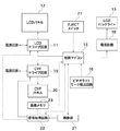
図2は主にLCDパネル12の制御に係る部分の制御回路の構成を示す図である。この制御回路はビデオカメラ本体1の内部に設けられる。この制御回路は、LCDパネル12を駆動するLCDドライブ回路11、カラービューファインダ6に配置されたCVFパネル20を駆動するCVFドライブ回路19、およびビデオカメラを制御する制御マイコン15を有する。また、制御回路は、LCDパネル12の矢印A方向の開閉(開閉状態)を検出する開閉検出スイッチ14、およびLCDパネル12の矢印B方向の回動を検出する反転検出スイッチ17を有する。この反転検出スイッチ17によって、LCDパネル12が被写体側に向いているか撮影者側に向いているかの方向検出が行われる。また、制御回路は、ビデオライトモードのON/OFFを検出するビデオライトモード検出回路16、およびLCDバックライト13に電源供給を行う電源回路18を有する。また、制御回路は、撮像素子、CDS回路、A/D変換器等(図示せず)を有し、撮影した画像データを出力する撮像部21、撮影した画像データに対し必要な信号処理を行う信号処理回路22、および信号処理された画像データを記憶する画像メモリ23を有する。
FIG. 2 is a diagram showing a configuration of a control circuit of a part mainly related to control of the
制御マイコン15は、LCDパネル12の開閉・反転の検出結果に応じて、LCDパネル12およびCVFパネル20における映像表示のON/OFFを制御する。また、ビデオライトモード検出回路16は、例えば撮影者による所定のメニュー操作やキー操作により設定あるいは選択されるビデオライトモードのON/OFFを検出する。ビデオライトモードのON状態が検出されると、LCDパネル12を全白表示にすることができる。LCDドライブ回路11およびCVFドライブ回路19は、それぞれ制御マイコン15からの制御信号に従って、別途入力される映像信号をLCDパネル12およびCVFパネル20に表示させるようにそれらを駆動する。
The
上記構成を有する撮像装置であるビデオカメラの動作について説明する。まず、ビデオカメラは、レンズ4を介して入射される被写体の光信号を、ビデオカメラ本体1に内蔵されたCCD(図示せず)により電気信号に変換して映像信号を得る。この映像信号は、信号処理回路22で各種信号処理が施されると、LCDパネル12に表示される。また、このとき録画ボタンを押すことで、内部に装填されたビデオテープなどの記録媒体に映像信号および音声信号が記録される。
An operation of the video camera which is the imaging apparatus having the above configuration will be described. First, the video camera obtains a video signal by converting an optical signal of a subject incident through the lens 4 into an electrical signal by a CCD (not shown) built in the video camera body 1. This video signal is displayed on the
前述したように、ビデオカメラ本体1には、撮影中の映像や再生した映像を表示するためのLCDパネル12が設けられている。このLCDパネル12は、ヒンジ部7によって図1の矢印A方向に開閉自在かつ図1の矢印B方向に回動自在である。すなわち、LCDパネル12は、撮影者側に向いた通常撮影状態と、被写体側つまりレンズ4と同方向に向いた対面撮影状態とに回動自在である。
As described above, the video camera main body 1 is provided with the
LCDパネル12をビデオライトとして使用していない状態では、通常撮影状態でも対面撮影状態でも、映像信号が表示されている。ここで、図1の状態を正転状態、この正転状態から図1の矢印A方向にLCDパネル12を閉じた状態を正転収納状態と言うこととする。また、図1の状態(正転状態)から矢印B方向にLCDパネル12を被写体側に回転した状態を対面状態(反転状態)、この対面状態から図1の矢印A方向にLCDパネル12を閉じた状態を反転収納状態と言うこととする。
When the
つぎに、LCDパネル12をビデオライトとして使用する際の動作について説明する。まず、ビデオカメラ本体1の電源を投入すると、ビデオカメラが撮影モードである場合、レンズ4から入射して光電変換された映像信号はLCDパネル12に表示される。
Next, an operation when the
そして、ビデオライトモード検出回路16からのビデオライトモードON信号が制御マイコン15に入力されると、制御マイコン15からLCDドライブ回路11に対し、LCDパネル12を全白に切り替えてビデオライトとして利用するように制御信号が送られる。
When the video light mode ON signal from the video light
LCDドライブ回路11は、制御マイコン15からの制御信号により、LCDパネル12に映像信号を出力することを中止し、その代わりに、LCDパネル12が全白表示になるような信号を送る。そして、このLCDパネル12を被写体側に向けて対面状態にすると、LCDパネル12をビデオライトとして使用することができる。このように、LCDパネル12からの光量が最大となって被写体を照射し、ビデオライトの機能を果たすことができる。また、必要に応じて、全白にしたときのLCDパネル12の光量をより増大させるため、LCDバックライト13の照度を上げるようにすることも可能である。すなわち、ビデオライトモード検出回路16がONを検出することで、制御マイコン15から電源回路18に制御信号が入力され、この電源回路18の電圧をアップすることにより、LCDバックライト13の照度を上げることがきる。なお、LCDバックライト13としては、直下形蛍光管、導光板付き蛍光管など、種々の方式のものを用いることができる。
In response to a control signal from the
つぎに、ビデオライトモードの解除方法について説明する。図3はビデオカメラの動作手順を示すフローチャートである。この動作プログラムは制御マイコン15内のROM(図示せず)に格納されており、制御マイコン15内のCPUによって実行される。
Next, a method for canceling the video light mode will be described. FIG. 3 is a flowchart showing the operation procedure of the video camera. This operation program is stored in a ROM (not shown) in the
まず、制御マイコン15は、ビデオライトモード検出回路16によってビデオライトモードがONであることが検出されたか否かを判別する(ステップS1)。ビデオライトモードがOFFであることが検出された場合、制御マイコン15はそのまま本処理を終了する。
First, the
一方、ビデオライトモードがONであることが検出された場合、制御マイコン15はLCDパネル12を全白表示に切り替える(ステップS2)。LCDパネル12が全白表示に切り替えられたビデオライトモードにおいて、制御マイコン15は、開閉検出スイッチ14の閉状態が検出されたか否かを判別する(ステップS3)。ここでは、開閉検出スイッチ14の閉状態が検出された場合、特定の状況が発生したと判断される。
On the other hand, when it is detected that the video light mode is ON, the
ステップS3で開閉検出スイッチ14の閉状態が検出されると、制御マイコン15は、ビデオライトモードを解除し、LCDパネル12の全白表示を終了させる(ステップS4)。この後、制御マイコン15は本処理を終了する。一方、ステップS3で開閉検出スイッチ14が開状態である場合、制御マイコン15は、ステップS2の処理に戻り、LCDパネル12の全白表示を保持する。
When the closed state of the open /
このように、第1の実施形態の撮像装置によれば、ビデオライトモードでLCDパネルが全白表示を行っている時、LCDパネルを閉状態にするだけで、ビデオライトモードが解除され、全白表示が終了する。従って、使用者がビデオライトモードの解除方法を容易に理解することができる。これにより、使用者の利便性が向上し、利便性のあるビデオライトモードの解除方法を提供することができる。 As described above, according to the imaging apparatus of the first embodiment, when the LCD panel is displaying all white in the video light mode, the video light mode is canceled only by closing the LCD panel, White display ends. Therefore, the user can easily understand how to cancel the video light mode. As a result, the convenience for the user is improved, and a convenient method for canceling the video light mode can be provided.
なお、上記実施形態では、LCDパネル12を閉状態にした時にビデオライトモードを解除しているが、正転収納状態の時のみビデオライトモードを解除するようにしてもよい。図4は他のビデオカメラの動作手順を示すフローチャートである。この動作プログラムは制御マイコン15内のROM(図示せず)に格納されており、制御マイコン15内のCPU(図示せず)によって実行される。
In the above embodiment, the video light mode is canceled when the
まず、制御マイコン15は、ビデオライトモード検出回路16によってビデオライトモードがONであることが検出されたか否かを判別する(ステップS11)。ビデオライトモードがOFFであることが検出された場合、制御マイコン15はそのまま本処理を終了する。
First, the
一方、ビデオライトモードがONであることが検出された場合、制御マイコン15はLCDパネル12を全白表示に切り替える(ステップS12)。LCDパネル12が全白表示に切り替えられたビデオライトモードにおいて、制御マイコン15は、反転検出スイッチ17によって正転状態であるか否かを検出する(ステップS13)。正転状態である場合、制御マイコン15は、開閉検出スイッチ14の閉状態が検出されたか否かを判別する(ステップS14)。
On the other hand, when it is detected that the video light mode is ON, the
開閉検出スイッチ14の閉状態が検出された場合、つまり正転収納状態である場合、制御マイコン15は、ビデオライトモードを解除し、LCDパネル12の全白表示を終了させる(ステップS15)。一方、ステップS13で反転検出スイッチ17によって反転状態であることが検出された場合、あるいはステップS14で開閉検出スイッチ14が開状態である場合、制御マイコン15は、ステップS12の処理に戻り、LCDパネル12の全白表示を保持する。この状態は、正転状態、対面状態および反転収納状態のいずれかに相当する。
When the closed state of the open /
このように、全白表示が不要な正転収納状態になった場合に限ってビデオライトモードを解除することで、使用者がビデオライトモードの解除方法をより容易に理解することができる。 As described above, by releasing the video light mode only when the forward rotation storage state in which all white display is unnecessary is required, the user can more easily understand how to release the video light mode.
[第2の実施形態]
第2の実施形態の撮像装置におけるビデオライトモードの解除方法について説明する。第2の実施形態の撮像装置の構成は、前記第1の実施形態とほぼ同一であるので、同一の構成要素については同一の符号を用いることでその説明を省略し、ここでは異なる構成について説明する。
[Second Embodiment]
A method for canceling the video light mode in the imaging apparatus according to the second embodiment will be described. Since the configuration of the imaging apparatus of the second embodiment is almost the same as that of the first embodiment, the description of the same components is omitted by using the same reference numerals, and different configurations are described here. To do.
図5は第2の実施形態における制御回路の構成を示すブロック図である。前記第1の実施形態と比べ、この制御回路には、キー操作検出回路51とタイマ52が追加されており、ビデオカメラ本体1に設けられた所定のキー(図示せず)に対するキー操作の有無の検出が可能であり、かつ最後のキー操作からの時間が計時可能である。なお、前記第1の実施形態おける開閉検出スイッチ14および反転検出スイッチ17は省かれている。
FIG. 5 is a block diagram showing a configuration of a control circuit in the second embodiment. Compared with the first embodiment, a key
図6はビデオカメラの動作手順を示すフローチャートである。この動作プログラムは制御マイコン15内のROM(図示せず)に格納されており、制御マイコン15内のCPU(図示せず)によって実行される。なお、この動作の起動時、タイマ52は初期値0にリセットされる。
FIG. 6 is a flowchart showing the operation procedure of the video camera. This operation program is stored in a ROM (not shown) in the
まず、制御マイコン15は、ビデオライトモード検出回路16によってビデオライトモードがONであることが検出されたか否かを判別する(ステップS21)。ビデオライトモードがOFFであることが検出された場合、制御マイコン15はそのまま本処理を終了する。
First, the
一方、ビデオライトモードがONであることが検出された場合、制御マイコン15はLCDパネル12を全白表示に切り替える(ステップS22)。LCDパネル12が全白表示に切り替えられたビデオライトモードにおいて、制御マイコン15は、キー操作検出回路51によりキー操作が行われていることが検出されたか否かを判断する(ステップS23)。
On the other hand, when it is detected that the video light mode is ON, the
キー操作検出回路51によりキー操作が行われていないと判断した場合、制御マイコン15は、最後のキー操作後からタイマ52により計時された時間が所定時間を経過したか否かを検出する(ステップS24)。タイマ52により計時された時間が所定時間を経過したことが検出されると、制御マイコン15は、ビデオライトモードを解除し、LCDパネル12の全白表示を終了させる(ステップS25)。この後、制御マイコン15は本処理を終了する。
When it is determined by the key
一方、ステップS23でキー操作検出回路51により何らかのキー操作が行われたと判断した場合、制御マイコン15は、ステップS22の処理に戻り、ビデオライトモードを保持してLCDパネル12を全白表示のままとする。また、このとき、制御マイコン15はタイマ52を初期値0にリセットする。また一方、ステップS24で最後のキー操作後からタイマ52により計時された時間が所定時間を経過していない場合、制御マイコン15は、ステップS22の処理に戻り、ビデオライトモードを保持してLCDパネル12を全白表示のままとする。
On the other hand, if it is determined in step S23 that any key operation has been performed by the key
このように、第2の実施形態の撮像装置によれば、ビデオライトモード移行後、いずれのキー操作も行われず、ある一定時間が経過すると、ビデオライトモードが解除され、全白表示が終了する。従って、誤操作でビデオライトモードに移行した際、使用者が故障と勘違いしてしまうことを低減させることができる。 As described above, according to the imaging apparatus of the second embodiment, after the video light mode shifts, no key operation is performed, and when a certain time elapses, the video light mode is canceled and the all-white display ends. . Therefore, it is possible to reduce a user's misunderstanding as a failure when shifting to the video light mode due to an erroneous operation.
[第3の実施形態]
第3の実施形態の撮像装置におけるビデオライトモードの解除方法について説明する。第3の実施形態の撮像装置の構成は、前記第1の実施形態とほぼ同一であるので、同一の構成要素については同一の符号を用いることでその説明を省略し、ここでは異なる構成について説明する。
[Third Embodiment]
A method for canceling the video light mode in the imaging apparatus according to the third embodiment will be described. Since the configuration of the imaging apparatus of the third embodiment is almost the same as that of the first embodiment, the description of the same components is omitted by using the same reference numerals, and different configurations are described here. To do.
図7は第3の実施形態における制御回路の構成を示すブロック図である。前記第1の実施形態と比べ、この制御回路には、記録媒体を外部に取り出すためのEJECTスイッチ71が追加されており、記録媒体をビデオカメラ本体1から外部に取り出すことが可能である。なお、前記第1の実施形態における開閉検出スイッチ14および反転検出スイッチ17は省かれている。
FIG. 7 is a block diagram showing the configuration of the control circuit in the third embodiment. Compared with the first embodiment, an
図8はビデオカメラの動作手順を示すフローチャートである。この動作プログラムは制御マイコン15内のROM(図示せず)に格納されており、制御マイコン15内のCPU(図示せず)によって実行される。
FIG. 8 is a flowchart showing the operation procedure of the video camera. This operation program is stored in a ROM (not shown) in the
まず、制御マイコン15は、ビデオライトモード検出回路16によってビデオライトモードがONであることが検出されたか否かを判別する(ステップS31)。ビデオライトモードがOFFであることが検出された場合、制御マイコン15はそのまま本処理を終了する。
First, the
一方、ビデオライトモードがONであることが検出された場合、制御マイコン15はLCDパネル12を全白表示に切り替える(ステップS32)。LCDパネル12が全白表示に切り替えられたビデオライトモードにおいて、制御マイコン15は、撮影者がEJECTスイッチ71を操作して記録媒体を外部に取り出すためのEJECT操作(取出し操作)が行われたか否かを判断する(ステップS33)。このステップS33の処理は取出検出手段に相当する。
On the other hand, when it is detected that the video light mode is ON, the
EJECT操作が行われたと判断した場合、制御マイコン15は、ビデオライトモードを解除し、LCDパネル12の全白表示を終了させる(ステップS34)。この後、制御マイコン15は本処理を終了する。
If it is determined that the EJECT operation has been performed, the
一方、ステップS33でEJECT操作が行われないと判断した場合、制御マイコン15は、ステップS32の処理に戻り、ビデオライトモードを保持してLCDパネル12を全白表示のままとする。この後、制御マイコン15は本処理を終了する。
On the other hand, if it is determined in step S33 that the EJECT operation is not performed, the
このように、第3の実施形態の撮像装置によれば、ビデオライトモードでLCDパネルが全白表示を行っている時、記録媒体をビデオカメラ本体から取り出す取出し操作により、ビデオライトモードが解除され、全白表示が終了する。これにより、記録媒体を交換する際、ビデオライトモードを解除する必要がなく、使用者の利便性が向上する。 As described above, according to the image pickup apparatus of the third embodiment, when the LCD panel performs all white display in the video light mode, the video light mode is canceled by the take-out operation of taking out the recording medium from the video camera body. All white display ends. Thereby, when exchanging the recording medium, it is not necessary to cancel the video light mode, and the convenience for the user is improved.
[第4の実施形態]
第4の実施形態の撮像装置におけるビデオライトモードの解除方法について説明する。図9は第4の実施形態における制御回路の構成を示すブロック図である。第4の実施形態の撮像装置の構成は、前記第1の実施形態とほぼ同一であるので、同一の構成要素については同一の符号を用いることでその説明を省略し、ここでは異なる構成について説明する。
[Fourth Embodiment]
A method for canceling the video light mode in the imaging apparatus according to the fourth embodiment will be described. FIG. 9 is a block diagram showing a configuration of a control circuit in the fourth embodiment. Since the configuration of the imaging apparatus of the fourth embodiment is almost the same as that of the first embodiment, the description of the same components is omitted by using the same reference numerals, and different configurations are described here. To do.
前記第1の実施形態と比べ、この制御回路には、メディア残量検出回路91(残容量検出手段に相当)が追加されており、記録媒体の残量検出が可能である。なお、第1の実施形態における開閉検出スイッチ14および反転検出スイッチ17は省かれている。
Compared to the first embodiment, a media remaining amount detection circuit 91 (corresponding to the remaining capacity detecting means) is added to the control circuit, and the remaining amount of the recording medium can be detected. Note that the open /
図10はビデオカメラの動作手順を示すフローチャートである。この動作プログラムは制御マイコン15内のROM(図示せず)に格納されており、制御マイコン15内のCPU(図示せず)によって実行される。
FIG. 10 is a flowchart showing the operation procedure of the video camera. This operation program is stored in a ROM (not shown) in the
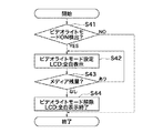
まず、制御マイコン15は、ビデオライトモード検出回路16によってビデオライトモードがONであることが検出されたか否かを判別する(ステップS41)。ビデオライトモードがOFFであることが検出された場合、制御マイコン15はそのまま本処理を終了する。
First, the
一方、ビデオライトモードがONであることが検出された場合、制御マイコン15はLCDパネル12を全白表示に切り替える(ステップS42)。LCDパネル12が全白表示に切り替えられたビデオライトモードにおいて、制御マイコン15は、メディア残量検出回路91によって検出される記録メディアの残容量がなくなったか否か、つまり残容量が閾値以下になったか否かを判断する(ステップS43)。
On the other hand, when it is detected that the video light mode is ON, the
記録メディアの残容量がなくなったことが検出された場合、制御マイコン15は、ビデオライトモードを解除し、LCDパネル12の全白表示を終了させる(ステップS44)。この後、制御マイコン15は本処理を終了する。
When it is detected that the remaining capacity of the recording medium is exhausted, the
一方、ステップS43で記録メディアの残容量がなくなったことが検出されなかった場合、制御マイコン15は、ステップS42の処理に戻り、ビデオライトモードを保持してLCDパネル12を全白表示のままとする。この後、制御マイコン15は本処理を終了する。
On the other hand, if it is not detected in step S43 that the remaining capacity of the recording medium has been exhausted, the
このように、第4の実施形態の撮像装置によれば、ビデオライトモードでLCDパネルが全白表示を行っている時、記録媒体の残容量がなくなると、ビデオライトモードが解除され、全白表示が終了する。これにより、ビデオライトモードの解除とともに記録媒体の終了が容易に理解でき、使用者の利便性が向上する。 As described above, according to the imaging apparatus of the fourth embodiment, when the remaining capacity of the recording medium is exhausted when the LCD panel is displaying all white in the video light mode, the video light mode is canceled and all white is displayed. The display ends. Accordingly, the termination of the recording medium can be easily understood together with the release of the video light mode, and the convenience for the user is improved.
[第5の実施形態]
第5の実施形態の撮像装置におけるビデオライトモードの解除方法について説明する。図11は第5の実施形態における制御回路の構成を示すブロック図である。第5の実施形態の撮像装置の構成は、前記第1の実施形態とほぼ同一であるので、同一の構成要素については同一の符号を用いることでその説明を省略し、ここでは異なる構成について説明する。
[Fifth Embodiment]
A method for canceling the video light mode in the imaging apparatus according to the fifth embodiment will be described. FIG. 11 is a block diagram showing a configuration of a control circuit in the fifth embodiment. Since the configuration of the imaging apparatus of the fifth embodiment is almost the same as that of the first embodiment, the description of the same components will be omitted by using the same reference numerals, and different configurations will be described here. To do.
前記第1の実施形態と比べ、この制御回路には、OSD表示回路101が追加されており、LCDパネル12にOSD表示が可能である。なお、前記第1の実施形態における開閉検出スイッチ14および反転検出スイッチ17は省かれている。
Compared with the first embodiment, an
前記第1〜第4の実施形態では、ビデオライトモード時にLCDパネル12を全白表示としていたが、第5の実施形態では、ビデオライトモードの解除方法を示す内容をLCDパネル12にOSD表示(オンスクリーンディスプレイ表示)により表示する。このOSD表示では、全白表示を示す信号に、ビデオライトモードの解除方法を示す内容の信号が重畳される。
In the first to fourth embodiments, the
図12は一例としてビデオライトモードの解除方法が常に表示し続けるLCDパネル12の画面を示す図である。この解除方法の表示はビデオライトモード時において常に継続される。ここでは、ビデオライトモードの解除方法を示す内容として、「ビデオライトモードはパネル閉で解除できます」というメッセージがテキストで表示されている。これにより、使用者は、全白表示に重畳されたビデオライトモードの解除方法を示す内容に従って、LCDパネル12を閉じる操作を行うだけで、ビデオライトモードは解除される。このように、使用者はビデオライトモードの解除方法を容易に理解できる。なお、ビデオライトモードの解除方法を示す内容の表示としては、テキスト表示に限らず、絵などの画像表示であってもよい。
FIG. 12 is a diagram showing a screen of the
図13は他の一例としてビデオライトモードの解除方法が表示されたLCDパネル12の画面を示す図である。ここでは、LCDパネル12の額縁にビデオライトモードの解除ボタン115が配置されている。この場合、ビデオライトモードの解除ボタン115を矢印で指し示すメッセージがLCDパネル12にテキストおよび画像で表示される。
FIG. 13 is a diagram showing a screen of the
このように、第5の実施形態の撮像装置によれば、ビデオライトモードでLCDパネルが全白表示を行っている時、ビデオライトモードの解除方法を示す内容を全白表示に重畳する。これにより、どのような状況においても容易にビデオライトモードの解除方法が分かる。 As described above, according to the imaging apparatus of the fifth embodiment, when the LCD panel performs the all white display in the video light mode, the content indicating the method for canceling the video light mode is superimposed on the all white display. This makes it easy to understand how to cancel the video light mode in any situation.
[第6の実施形態]
第6の実施形態の撮像装置におけるビデオライトモードの解除方法について説明する。図14は第6の実施形態における制御回路の構成を示すブロック図である。第6の実施形態の撮像装置の構成は、前記第1の実施形態とほぼ同一であるので、同一の構成要素については同一の符号を用いることでその説明を省略し、ここでは異なる構成について説明する。
[Sixth Embodiment]
A method for canceling the video light mode in the imaging apparatus according to the sixth embodiment will be described. FIG. 14 is a block diagram showing a configuration of a control circuit in the sixth embodiment. Since the configuration of the imaging apparatus of the sixth embodiment is almost the same as that of the first embodiment, the description of the same components will be omitted by using the same reference numerals, and different configurations will be described here. To do.
前記第1の実施形態と比べ、この制御回路には、レックレビュー再生回路131が追加されており、撮影した映像を確認するレックビューが可能である。なお、前記第1の実施形態における開閉検出スイッチ14および反転検出スイッチ17は省かれている。
Compared to the first embodiment, a REC
図15はビデオカメラの動作手順を示すフローチャートである。この動作プログラムは制御マイコン15内のROM(図示せず)に格納されており、制御マイコン15内のCPU(図示せず)によって実行される。
FIG. 15 is a flowchart showing the operation procedure of the video camera. This operation program is stored in a ROM (not shown) in the
まず、制御マイコン15は、ビデオライトモード検出回路16によってビデオライトモードがONであることが検出されたか否かを判別する(ステップS61)。ビデオライトモードがOFFであることが検出された場合、制御マイコン15はそのまま本処理を終了する。
First, the
一方、ビデオライトモードがONであることが検出された場合、制御マイコン15はLCDパネル12を全白表示に切り替える(ステップS62)。LCDパネル12が全白表示に切り替えられたビデオライトモードにおいて、制御マイコン15は、レックレビュー再生回路131により、レックレビューが開始されたか否かを判断する(ステップS63)。
On the other hand, when it is detected that the video light mode is ON, the
レックレビューが開始された場合、制御マイコン15は、ビデオライトモードを解除し、LCDパネル12の全白表示を終了させる(ステップS64)。この後、制御マイコン15は、レックレビューが終了したか否かを判別する(ステップS65)。レックレビューが終了した場合、制御マイコン15は、ステップS62の処理に戻り、LCDパネル12を全白表示に切り替える。一方、ステップS65でレックレビューが未終了である場合、制御マイコン15は本処理を終了する。
When the REC review is started, the
また一方、ステップS63でレックレビューが開始されなかった場合、制御マイコン15は、ステップS62の処理に戻り、ビデオライトモードを保持してLCDパネル12を全白表示のままとする。
On the other hand, if the REC review is not started in step S63, the
このように、第6の実施形態の撮像装置によれば、ビデオライトモードでLCDパネルが全白表示を行っている時、レックレビューが開始されると、ビデオライトモードを解除し、レックレビューが終了すると、ビデオライトモードに復帰する。これにより、LCDパネルによるビデオライトモードの全白表示を再開してLCDパネルによる表示を、撮影した映像の再生に簡単に切り替えることができ、撮影した映像の確認が容易となる。 As described above, according to the imaging device of the sixth embodiment, when the REC review is started when the LCD panel is displaying all white in the video light mode, the video light mode is canceled and the REC review is performed. When finished, the video light mode is restored. Thereby, the all white display in the video light mode on the LCD panel can be resumed, and the display on the LCD panel can be easily switched to the reproduction of the photographed image, and the confirmation of the photographed image becomes easy.
なお、本発明は、上記実施形態の構成に限られるものではなく、特許請求の範囲で示した機能、または本実施形態の構成が持つ機能が達成できる構成であればどのようなものであっても適用可能である。 The present invention is not limited to the configuration of the above-described embodiment, and any configuration can be used as long as the functions shown in the claims or the functions of the configuration of the present embodiment can be achieved. Is also applicable.
例えば、上記各実施形態では、表示手段として、バックライト方式のLCDパネルを用いているが、有機ELディスプレイなどの自発光型の表示手段を用いてもよい。その他、表面電界ディスプレイ(SED)、プラズマディスプレイなどを用いてもよい。 For example, in each of the above embodiments, a backlight type LCD panel is used as the display means, but a self-luminous display means such as an organic EL display may be used. In addition, a surface electric field display (SED), a plasma display, or the like may be used.
また、上記実施形態では、液晶パネルがビデオカメラ本体の側面に対し、開閉かつ回動自在に設けられていたが、撮像装置はこのような構造に限られるものではない。例えば、ビデオカメラ本体の前面と背面とに液晶パネルが着脱自在に取り付けられる構造の撮像装置であってもよい。 In the above embodiment, the liquid crystal panel is provided to be openable / closable and rotatable with respect to the side surface of the video camera body. However, the imaging apparatus is not limited to such a structure. For example, an imaging apparatus having a structure in which a liquid crystal panel is detachably attached to the front and back of the video camera main body may be used.
1 ビデオカメラ本体
11 LCDドライブ回路
12 LCDパネル
14 開閉検出スイッチ
15 制御マイコン
16 ビデオライトモード検出回路
17 反転検出スイッチ
51 キー操作検出回路
71 EJECTスイッチ
91 メディア残量検出回路
101 OSD表示回路
131 レックレビュー再生回路
DESCRIPTION OF SYMBOLS 1
Claims (16)
前記撮像された被写体の映像表示あるいは全白表示を行う表示手段と、
前記表示手段をビデオライトとして使用するためのビデオライトモードを選択する選択手段と、
前記ビデオライトモードが選択されている時、特定の状況が発生した場合、前記ビデオライトモードを解除して前記表示手段による全白表示を終了させる表示制御手段とを備えたことを特徴とする撮像装置。 An imaging device for imaging a subject,
Display means for performing video display or all white display of the imaged subject;
Selecting means for selecting a video light mode for using the display means as a video light;
An imaging device comprising: display control means for canceling the video light mode and ending all white display by the display means when a specific situation occurs when the video light mode is selected apparatus.
前記撮像された被写体の映像表示あるいは全白表示を行う表示手段と、
前記表示手段の開閉状態を検出する開閉検出手段と、
前記表示手段をビデオライトとして使用するためのビデオライトモードを選択する選択手段と、
前記ビデオライトモードが選択されている時、前記開閉検出手段によって前記表示手段が開状態であることが検出された場合、前記表示手段を全白表示に切り替え、一方、前記表示手段が閉状態であることが検出された場合、前記ビデオライトモードを解除して前記表示手段による全白表示を終了させる表示制御手段とを備えたことを特徴とする撮像装置。 An imaging device for imaging a subject,
Display means for performing video display or all white display of the imaged subject;
Open / close detecting means for detecting an open / closed state of the display means;
Selecting means for selecting a video light mode for using the display means as a video light;
When the video light mode is selected and the open / close detection means detects that the display means is open, the display means is switched to all white display, while the display means is closed. An image pickup apparatus comprising: display control means for canceling the video light mode and ending all white display by the display means when it is detected.
前記表示制御手段は、前記ビデオライトモードが選択されている時、前記方向検出手段によって前記表示手段が前記撮影者側に向いていることが検出され、かつ前記開閉検出手段によって前記表示手段が閉状態であることが検出された場合、前記ビデオライトモードを解除して前記表示手段による全白表示を終了させることを特徴とする請求項2記載の撮像装置。 Direction detecting means for detecting that the display means is directed toward the subject or the photographer;
When the video light mode is selected, the display control means detects that the display means is facing the photographer by the direction detection means, and the display means is closed by the open / close detection means. 3. The image pickup apparatus according to claim 2, wherein when the state is detected, the video light mode is canceled and the all-white display by the display unit is terminated.
前記撮像された被写体の映像表示あるいは全白表示を行う表示手段と、
前記撮像装置に対してキー操作が行われたことを検出する操作検出手段と、
最後に前記キー操作が行われたことが検出されてからの時間を計時する計時手段と、
前記表示手段をビデオライトとして使用するためのビデオライトモードを選択する選択手段と、
前記ビデオライトモードが選択されている時、前記表示手段を全白表示に切り替え、一方、前記計時手段によって計時された時間が所定時間を経過した場合、前記ビデオライトモードを解除して前記表示手段による全白表示を終了させる表示制御手段とを備えたことを特徴とする撮像装置。 An imaging device for imaging a subject,
Display means for performing video display or all white display of the imaged subject;
Operation detecting means for detecting that a key operation has been performed on the imaging device;
Clocking means for timing the time since the last time the key operation was detected;
Selecting means for selecting a video light mode for using the display means as a video light;
When the video light mode is selected, the display means is switched to all white display. On the other hand, when a predetermined time has passed, the video light mode is canceled and the display means is displayed. An image pickup apparatus comprising: display control means for ending the all white display according to the above.
前記撮像された被写体の映像表示あるいは全白表示を行う表示手段と、
前記撮像装置に着脱自在に設けられ、前記撮像された映像が記録される記録媒体と、
前記記録媒体を外部に取り出すための取出し操作が行われたことを検出する取出検出手段と、
前記表示手段をビデオライトとして使用するためのビデオライトモードを選択する選択手段と、
前記ビデオライトモードが選択されている時、前記表示手段を全白表示に切り替え、一方、前記取出し操作が行われたことが検出された場合、前記ビデオライトモードを解除して前記表示手段による全白表示を終了させる表示制御手段とを備えたことを特徴とする撮像装置。 An imaging device for imaging a subject,
Display means for performing video display or all white display of the imaged subject;
A recording medium that is detachably provided in the imaging device and on which the captured video is recorded;
A take-out detecting means for detecting that a take-out operation for taking out the recording medium is performed;
Selecting means for selecting a video light mode for using the display means as a video light;
When the video light mode is selected, the display means is switched to all white display. On the other hand, when it is detected that the take-out operation has been performed, the video light mode is canceled and the display means An image pickup apparatus comprising: display control means for terminating white display.
前記撮像された被写体の映像表示あるいは全白表示を行う表示手段と、
前記撮像装置に設けられ、前記撮像された映像が記録される記録媒体と、
前記記録媒体の残容量を検出する残容量検出手段と、
前記表示手段をビデオライトとして使用するためのビデオライトモードを選択する選択手段と、
前記ビデオライトモードが選択されている時、前記表示手段を全白表示に切り替え、一方、前記残容量検出手段によって前記記録媒体の残容量が閾値以下となった場合、前記ビデオライトモードを解除して前記表示手段による全白表示を終了させる表示制御手段とを備えたことを特徴とする撮像装置。 An imaging device for imaging a subject,
Display means for performing video display or all white display of the imaged subject;
A recording medium provided in the imaging apparatus, on which the captured video is recorded;
A remaining capacity detecting means for detecting a remaining capacity of the recording medium;
Selecting means for selecting a video light mode for using the display means as a video light;
When the video light mode is selected, the display means is switched to all white display. On the other hand, when the remaining capacity of the recording medium is equal to or less than a threshold by the remaining capacity detecting means, the video light mode is canceled. An image pickup apparatus comprising display control means for ending all white display by the display means.
前記撮像された被写体の映像表示あるいは全白表示を行う表示手段と、
前記表示手段をビデオライトとして使用するためのビデオライトモードを選択する選択手段と、
前記ビデオライトモードが選択されている時、前記表示手段を全白表示に切り替える表示制御手段と、
前記切り替えられた全白表示に前記ビデオライトモードの解除方法を示す内容を重畳する重畳手段とを備え、
前記表示制御手段は、前記重畳されたビデオライトモードの解除方法を示す内容に従って、所定の操作が行われた場合、前記ビデオライトモードを解除して前記表示手段による全白表示を終了させることを特徴とする撮像装置。 An imaging device for imaging a subject,
Display means for performing video display or all white display of the imaged subject;
Selecting means for selecting a video light mode for using the display means as a video light;
Display control means for switching the display means to all white display when the video light mode is selected;
Superimposing means for superimposing content indicating a method for canceling the video light mode on the switched white display,
The display control means cancels the video light mode and terminates all white display by the display means when a predetermined operation is performed in accordance with the content indicating the method for canceling the superimposed video light mode. An imaging device that is characterized.
前記撮像装置の表示手段が前記撮像された被写体の映像表示あるいは全白表示を行う表示ステップと、
前記撮像装置の選択手段が前記表示手段をビデオライトとして使用するためのビデオライトモードを選択する選択ステップと、
前記撮像装置の表示制御手段が、前記ビデオライトモードが選択されている時、特定の状況が発生した場合、前記ビデオライトモードを解除して前記表示手段による全白表示を終了させる表示制御ステップとを有することを特徴とする表示制御方法。 A display control method for an imaging apparatus that images a subject,
A display step in which the display unit of the imaging apparatus performs video display or all-white display of the imaged subject;
A selection step in which the selection unit of the imaging device selects a video light mode for using the display unit as a video light;
A display control step in which the display control means of the imaging apparatus cancels the video light mode and terminates the all-white display by the display means when a specific situation occurs when the video light mode is selected; A display control method comprising:
前記撮像装置の表示手段が前記撮像された被写体の映像表示あるいは全白表示を行う表示ステップと、
前記撮像装置の開閉検出手段が前記表示手段の開閉状態を検出する開閉検出ステップと、
前記撮像装置の選択手段が前記表示手段をビデオライトとして使用するためのビデオライトモードを選択する選択ステップと、
前記撮像装置の表示制御手段が、前記ビデオライトモードが選択されている時、前記開閉検出ステップで前記表示手段が開状態であることが検出された場合、前記表示手段を全白表示に切り替え、一方、前記表示手段が閉状態であることが検出された場合、前記ビデオライトモードを解除して前記表示手段による全白表示を終了させる表示制御ステップとを有することを特徴とする表示制御方法。 A display control method for an imaging apparatus that images a subject,
A display step in which the display unit of the imaging apparatus performs video display or all-white display of the imaged subject;
An open / close detection step in which the open / close detection means of the imaging device detects an open / closed state of the display means;
A selection step in which the selection unit of the imaging device selects a video light mode for using the display unit as a video light;
When the display control means of the imaging device detects that the display means is in the open state in the open / close detection step when the video light mode is selected, the display means is switched to all white display, On the other hand, a display control method comprising: a display control step of canceling the video light mode and ending all white display by the display means when it is detected that the display means is in a closed state.
前記表示制御ステップでは、前記ビデオライトモードが選択されている時、前記方向検出ステップで前記表示手段が前記撮影者側に向いていることが検出され、かつ前記開閉検出ステップで前記表示手段が閉状態であることが検出された場合、前記ビデオライトモードを解除して前記表示手段による全白表示を終了させることを特徴とする請求項9記載の表示制御方法。 The direction detection means of the imaging device includes a direction detection step of detecting that the display means is directed to the subject side or the photographer side;
In the display control step, when the video light mode is selected, it is detected in the direction detection step that the display means is facing the photographer side, and the display means is closed in the open / close detection step. The display control method according to claim 9, wherein when the state is detected, the video light mode is canceled and the all-white display by the display unit is ended.
前記撮像装置の表示手段が前記撮像された被写体の映像表示あるいは全白表示を行う表示ステップと、
前記撮像装置の操作検出手段が、前記撮像装置に対してキー操作が行われたことを検出する操作検出ステップと、
前記撮像装置の計時手段が、最後に前記キー操作が行われたことが検出されてからの時間を計時する計時ステップと、
前記撮像装置の選択手段が前記表示手段をビデオライトとして使用するためのビデオライトモードを選択する選択ステップと、
前記撮像装置の表示制御手段が、前記ビデオライトモードが選択されている時、前記表示手段を全白表示に切り替え、一方、前記計時ステップで計時された時間が所定時間を経過した場合、前記ビデオライトモードを解除して前記表示手段による全白表示を終了させる表示制御ステップとを有することを特徴とする表示制御方法。 A display control method for an imaging apparatus that images a subject,
A display step in which the display unit of the imaging apparatus performs video display or all-white display of the imaged subject;
An operation detection step in which the operation detection means of the imaging device detects that a key operation has been performed on the imaging device;
A time measuring step for measuring a time from when the time measuring means of the image pickup device was detected that the key operation was last performed;
A selection step in which the selection unit of the imaging device selects a video light mode for using the display unit as a video light;
When the video light mode is selected, the display control means of the imaging device switches the display means to all white display, while if the time counted in the time measuring step has passed a predetermined time, the video A display control step of canceling the light mode and ending the all-white display by the display means.
前記撮像装置の表示手段が前記撮像された被写体の映像表示あるいは全白表示を行う表示ステップと、
前記撮像装置の取出検出手段が、前記撮像装置に着脱自在に設けられ、前記撮像された映像が記録される記録媒体を外部に取り出すための取出し操作が行われたことを検出する取出検出ステップと、
前記撮像装置の選択手段が前記表示手段をビデオライトとして使用するためのビデオライトモードを選択する選択ステップと、
前記撮像装置の表示制御手段が、前記ビデオライトモードが選択されている時、前記表示手段を全白表示に切り替え、一方、前記取出し操作が行われたことが検出された場合、前記ビデオライトモードを解除して前記表示手段による全白表示を終了させる表示制御ステップとを有することを特徴とする表示制御方法。 A display control method for an imaging apparatus that images a subject,
A display step in which the display unit of the imaging apparatus performs video display or all-white display of the imaged subject;
An extraction detection step for detecting that an extraction operation for taking out a recording medium in which the extraction detection means of the imaging apparatus is detachably provided in the imaging apparatus and on which the captured video is recorded is performed; ,
A selection step in which the selection unit of the imaging device selects a video light mode for using the display unit as a video light;
When the display control means of the imaging device switches the display means to all white display when the video light mode is selected, on the other hand, when it is detected that the take-out operation has been performed, the video light mode And a display control step of terminating the all-white display by the display means.
前記撮像装置の表示手段が前記撮像された被写体の映像表示あるいは全白表示を行う表示ステップと、
前記撮像装置の残容量検出手段が、前記撮像装置に設けられ、前記撮像された映像が記録される記録媒体の残容量を検出する残容量検出ステップと、
前記撮像装置の選択手段が、前記表示手段をビデオライトとして使用するためのビデオライトモードを選択する選択ステップと、
前記撮像装置の表示制御手段が、前記ビデオライトモードが選択されている時、前記表示手段を全白表示に切り替え、一方、前記残容量検出ステップで前記記録媒体の残容量が閾値以下となった場合、前記ビデオライトモードを解除して前記表示手段による全白表示を終了させる表示制御ステップとを有することを特徴とする表示制御方法。 A display control method for an imaging apparatus that images a subject,
A display step in which the display unit of the imaging apparatus performs video display or all-white display of the imaged subject;
A remaining capacity detecting step of detecting a remaining capacity of a recording medium in which the remaining capacity detecting means of the imaging apparatus is provided in the imaging apparatus and the captured video is recorded;
A selection step in which the selection unit of the imaging apparatus selects a video light mode for using the display unit as a video light;
When the video light mode is selected, the display control unit of the imaging apparatus switches the display unit to all white display, while the remaining capacity of the recording medium becomes equal to or less than a threshold value in the remaining capacity detecting step. A display control step of canceling the video light mode and ending all white display by the display means.
前記撮像装置の表示手段が前記撮像された被写体の映像表示あるいは全白表示を行う表示ステップと、
前記撮像装置の選択手段が前記表示手段をビデオライトとして使用するためのビデオライトモードを選択する選択ステップと、
前記撮像装置の表示制御手段が、前記ビデオライトモードが選択されている時、前記表示手段を全白表示に切り替える表示制御ステップと、
前記撮像装置の重畳手段が前記切り替えられた全白表示に前記ビデオライトモードの解除方法を示す内容を重畳する重畳ステップとを有し、
前記表示制御手段が、前記重畳されたビデオライトモードの解除方法を示す内容に従って、所定の操作が行われた場合、前記ビデオライトモードを解除して前記表示手段による全白表示を終了させることを特徴とする表示制御方法。 A display control method for an imaging apparatus that images a subject,
A display step in which the display unit of the imaging apparatus performs video display or all-white display of the imaged subject;
A selection step in which the selection unit of the imaging device selects a video light mode for using the display unit as a video light;
A display control step of switching the display means to all white display when the video light mode is selected by the display control means of the imaging device;
A superimposing step in which the superimposing means of the imaging device superimposes content indicating a method of canceling the video light mode on the switched all-white display,
The display control means cancels the video light mode and terminates all white display by the display means when a predetermined operation is performed in accordance with the content indicating the method for canceling the superimposed video light mode. A characteristic display control method.
前記撮像された被写体の映像表示あるいは全白表示を行う表示手段と、
前記撮像された映像を再生するレックレビュー再生手段と、
前記表示手段をビデオライトとして使用するためのビデオライトモードを選択する選択手段と、
前記ビデオライトモードが選択されている時、前記表示手段を全白表示に切り替え、一方、前記レックレビュー再生手段によってレックレビューが開始された場合、前記ビデオライトモードを解除して前記表示手段による全白表示を終了させ、その後、前記レックレビュー再生手段による映像の再生が終了した場合、前記ビデオライトモードに復帰して前記表示手段による全白表示を再開させる表示制御手段とを備えたことを特徴とする撮像装置。 An imaging device for imaging a subject,
Display means for performing video display or all white display of the imaged subject;
Rec review playback means for playing back the captured video;
Selecting means for selecting a video light mode for using the display means as a video light;
When the video light mode is selected, the display means is switched to all white display. On the other hand, when the REC review is started by the REC review playback means, the video light mode is canceled and the display means And a display control means for returning to the video light mode and resuming all white display by the display means when the white display is finished and then the video playback by the REC review playback means is finished. An imaging device.
前記撮像装置の表示手段が前記撮像された被写体の映像表示あるいは全白表示を行う表示ステップと、
前記撮像装置のレックレビュー再生手段が前記撮像された映像を再生するレックレビュー再生ステップと、
前記撮像装置の選択手段が前記表示手段をビデオライトとして使用するためのビデオライトモードを選択する選択ステップと、
前記撮像装置の表示制御手段が、前記ビデオライトモードが選択されている時、前記表示手段を全白表示に切り替え、一方、前記レックレビュー再生手段によってレックレビューが開始された場合、前記ビデオライトモードを解除して前記表示手段による全白表示を終了させ、その後、前記レックレビュー再生手段による映像の再生が終了した場合、前記ビデオライトモードに復帰して前記表示手段による全白表示を再開させる表示制御ステップとを有することを特徴とする撮像装置の表示制御方法。 A display control method for an imaging apparatus that images a subject,
A display step in which the display unit of the imaging apparatus performs video display or all-white display of the imaged subject;
A REC review playback step in which the REC review playback means of the imaging device plays back the captured video;
A selection step in which the selection unit of the imaging device selects a video light mode for using the display unit as a video light;
When the video light mode is selected, the display control means of the imaging device switches the display means to all white display, while when the REC review is started by the REC review playback means, the video light mode Is displayed to terminate the all-white display by the display means, and after that, when the reproduction of the video by the REC review reproduction means is terminated, the display returns to the video light mode and the all-white display by the display means is resumed. A display control method for the image pickup apparatus.
Priority Applications (4)
| Application Number | Priority Date | Filing Date | Title |
|---|---|---|---|
| JP2007302127A JP2009130539A (en) | 2007-11-21 | 2007-11-21 | Image pickup apparatus and display controlling method therefor |
| CN2010105661892A CN101982968A (en) | 2007-11-02 | 2008-10-31 | Image pickup apparatus |
| CN2010105661869A CN101982967B (en) | 2007-11-02 | 2008-10-31 | Image pickup apparatus |
| US12/263,449 US20090115880A1 (en) | 2007-11-02 | 2008-10-31 | Image pickup apparatus and display controlling method therefor |
Applications Claiming Priority (1)
| Application Number | Priority Date | Filing Date | Title |
|---|---|---|---|
| JP2007302127A JP2009130539A (en) | 2007-11-21 | 2007-11-21 | Image pickup apparatus and display controlling method therefor |
Publications (2)
| Publication Number | Publication Date |
|---|---|
| JP2009130539A true JP2009130539A (en) | 2009-06-11 |
| JP2009130539A5 JP2009130539A5 (en) | 2010-12-24 |
Family
ID=40821040
Family Applications (1)
| Application Number | Title | Priority Date | Filing Date |
|---|---|---|---|
| JP2007302127A Pending JP2009130539A (en) | 2007-11-02 | 2007-11-21 | Image pickup apparatus and display controlling method therefor |
Country Status (1)
| Country | Link |
|---|---|
| JP (1) | JP2009130539A (en) |
Cited By (1)
| Publication number | Priority date | Publication date | Assignee | Title |
|---|---|---|---|---|
| JP2017138846A (en) * | 2016-02-04 | 2017-08-10 | レノボ・シンガポール・プライベート・リミテッド | Information processing apparatus, display method by the same, and computer-executable program |
Citations (1)
| Publication number | Priority date | Publication date | Assignee | Title |
|---|---|---|---|---|
| JP2004236104A (en) * | 2003-01-31 | 2004-08-19 | Matsushita Electric Ind Co Ltd | Imaging device |
-
2007
- 2007-11-21 JP JP2007302127A patent/JP2009130539A/en active Pending
Patent Citations (1)
| Publication number | Priority date | Publication date | Assignee | Title |
|---|---|---|---|---|
| JP2004236104A (en) * | 2003-01-31 | 2004-08-19 | Matsushita Electric Ind Co Ltd | Imaging device |
Cited By (1)
| Publication number | Priority date | Publication date | Assignee | Title |
|---|---|---|---|---|
| JP2017138846A (en) * | 2016-02-04 | 2017-08-10 | レノボ・シンガポール・プライベート・リミテッド | Information processing apparatus, display method by the same, and computer-executable program |
Similar Documents
| Publication | Publication Date | Title |
|---|---|---|
| JP4631811B2 (en) | Imaging device | |
| JP6739012B2 (en) | Imaging device and imaging device system | |
| US20090115880A1 (en) | Image pickup apparatus and display controlling method therefor | |
| JP4301241B2 (en) | Digital camera and power supply control method thereof | |
| JP2009130539A (en) | Image pickup apparatus and display controlling method therefor | |
| JP5433459B2 (en) | Imaging device | |
| JP4035491B2 (en) | Imaging apparatus and control method thereof | |
| JP2005151349A (en) | Digital camera | |
| JP2008118263A (en) | Photography apparatus and heat generation suppressing method | |
| JP4184166B2 (en) | Audio recording / playback device | |
| WO2022145102A1 (en) | Image processing apparatus, image processing apparatus control method, program, and recording medium | |
| JP5024332B2 (en) | Imaging apparatus and method, reproducing apparatus and method, and program | |
| JP2009117993A (en) | Imaging apparatus and display control method thereof | |
| JP4751360B2 (en) | Digital camera, control method thereof and recording medium | |
| JP4720952B2 (en) | Digital camera, control method thereof and recording medium | |
| JP4123288B2 (en) | Imaging device | |
| JP4032417B2 (en) | Image recording device | |
| JP2009130540A (en) | Image pickup apparatus and display controlling method therefor | |
| JP2022104262A (en) | Image processing apparatus, image processing apparatus control method, program, and recording medium | |
| JP2022104231A (en) | Image processing apparatus, image processing apparatus control method, program, and recording medium | |
| JP2004040602A (en) | Digital camera | |
| JP2004072222A (en) | Electronic camera | |
| JP2010278758A (en) | Imaging device | |
| JP4687007B2 (en) | Digital camera and display method | |
| JP4720950B2 (en) | Digital camera, control method thereof and recording medium |
Legal Events
| Date | Code | Title | Description |
|---|---|---|---|
| A521 | Request for written amendment filed |
Free format text: JAPANESE INTERMEDIATE CODE: A523 Effective date: 20101104 |
|
| A621 | Written request for application examination |
Free format text: JAPANESE INTERMEDIATE CODE: A621 Effective date: 20101104 |
|
| A977 | Report on retrieval |
Free format text: JAPANESE INTERMEDIATE CODE: A971007 Effective date: 20120313 |
|
| A131 | Notification of reasons for refusal |
Free format text: JAPANESE INTERMEDIATE CODE: A131 Effective date: 20120321 |
|
| A02 | Decision of refusal |
Free format text: JAPANESE INTERMEDIATE CODE: A02 Effective date: 20120710 |