JP2009128014A - Beam irradiation apparatus - Google Patents
Beam irradiation apparatus Download PDFInfo
- Publication number
- JP2009128014A JP2009128014A JP2007299713A JP2007299713A JP2009128014A JP 2009128014 A JP2009128014 A JP 2009128014A JP 2007299713 A JP2007299713 A JP 2007299713A JP 2007299713 A JP2007299713 A JP 2007299713A JP 2009128014 A JP2009128014 A JP 2009128014A
- Authority
- JP
- Japan
- Prior art keywords
- light
- actuator
- light receiving
- beam irradiation
- specific position
- Prior art date
- Legal status (The legal status is an assumption and is not a legal conclusion. Google has not performed a legal analysis and makes no representation as to the accuracy of the status listed.)
- Withdrawn
Links
Images


Abstract
Description
本発明は、目標領域にレーザ光を照射するビーム照射装置に関し、特に、目標領域にレーザ光を照射したときの反射光をもとに、目標領域内における障害物の有無や障害物までの距離を検出する、いわゆるレーザレーザに搭載されるビーム照射装置に用いて好適なものである。 The present invention relates to a beam irradiation apparatus that irradiates a target area with laser light, and in particular, based on reflected light when the target area is irradiated with laser light, the presence or absence of an obstacle in the target area and the distance to the obstacle. It is suitable for use in a beam irradiation device mounted on a so-called laser laser.
近年、走行時の安全性を高めるために、走行方向前方にレーザ光を照射し、その反射光の状態から、目標領域内における障害物の有無や障害物までの距離を検出するレーザレーダが、家庭用乗用車等に搭載されている。一般に、レーザレーダは、レーザ光を目標領域内でスキャンさせ、各スキャン位置における反射光の有無から、各スキャン位置における障害物の有無を検出し、さらに、各スキャン位置におけるレーザ光の照射タイミングから反射光の受光タイミングまでの所要時間をもとに、そのスキャン位置における障害物までの距離を検出するものである。 In recent years, in order to improve safety during traveling, a laser radar that irradiates laser light forward in the traveling direction and detects the presence or absence of an obstacle in the target area and the distance to the obstacle from the state of the reflected light, It is installed in home passenger cars. In general, a laser radar scans a laser beam within a target area, detects the presence or absence of an obstacle at each scan position from the presence or absence of reflected light at each scan position, and further determines from the irradiation timing of the laser light at each scan position. Based on the time required to receive the reflected light, the distance to the obstacle at the scan position is detected.
これまで、レーザ光のスキャン機構として、ポリゴンミラーを用いるスキャン機構と、走査用レンズを2次元駆動するレンズ駆動タイプのスキャン機構(たとえば、以下の特許文献1参照)が知られている。 Conventionally, as a laser beam scanning mechanism, a scanning mechanism using a polygon mirror and a lens driving type scanning mechanism for driving a scanning lens two-dimensionally (for example, see Patent Document 1 below) are known.
また、これらスキャン機構とは異なる新たなスキャン機構として、出願人は、先に特願2006−121762号を出願し、ミラー回動タイプのスキャン機構を提案している。このスキャン機構では、ミラーが2軸駆動可能に支持され、コイルとマグネット間の電磁駆動力によって、ミラーが各駆動軸を軸として回動される。レーザ光は、ミラーに斜め方向から入射され、その反射光が目標領域に向けて照射される。ミラーが各駆動軸を軸として2次元駆動されることにより、レーザ光が、目標領域内において、2次元方向に走査される。 As a new scanning mechanism different from these scanning mechanisms, the applicant has previously filed Japanese Patent Application No. 2006-121762 and has proposed a mirror rotation type scanning mechanism. In this scan mechanism, the mirror is supported so that it can be driven in two axes, and the mirror is rotated about each drive shaft by an electromagnetic drive force between the coil and the magnet. The laser light is incident on the mirror from an oblique direction, and the reflected light is irradiated toward the target area. The mirror is driven two-dimensionally around each drive axis, whereby the laser beam is scanned in a two-dimensional direction within the target area.
レーザレーダの検出精度を高めるには、レーザ光を目標領域内において適正にスキャンさせる必要がある。このため、ビーム照射装置では、レーザ光のスキャン位置を所期の軌道に沿わせるためのサーボ動作が必要となる。上記ミラー回動方式のスキャン機構では、目標領域におけるレーザ光のスキャン位置がミラーの回動位置に一対一に対応する。よって、レーザ光のスキャン位置はミラーの回動位置を検出することによって検出可能である。ここで、ミラーの回動位置は、たとえば、ミラーに伴って回動する別部材の回動位置を検出することにより検出することができる。 In order to increase the detection accuracy of the laser radar, it is necessary to appropriately scan the laser beam within the target area. For this reason, in the beam irradiation apparatus, a servo operation is required to align the scan position of the laser beam along the intended trajectory. In the mirror rotation type scanning mechanism, the scan position of the laser beam in the target area corresponds one-to-one with the rotation position of the mirror. Therefore, the scan position of the laser beam can be detected by detecting the rotational position of the mirror. Here, the rotation position of the mirror can be detected, for example, by detecting the rotation position of another member that rotates with the mirror.
図14は、ミラーの回動位置を検出するための構成例を示す図である。同図(a)は、別部材として平行平板状の透明体を用いる場合の構成例、同図(b)は、別部材としてミラーを用いる場合の構成例である。 FIG. 14 is a diagram illustrating a configuration example for detecting the rotational position of the mirror. FIG. 5A shows a configuration example when a parallel plate-shaped transparent body is used as another member, and FIG. 4B shows a configuration example when a mirror is used as another member.
同図(a)において、601は半導体レーザ、602は透明体、603は光検出器(PSD:Position Sensing Device)である。半導体レーザ601から出射されたレーザ光(サーボ光)は、レーザ光軸に対し傾いて配置された透明体602によって屈折され、光検出器603に受光される。ここで、透明体602が矢印のように回動すると、サーボ光の光路が図中の点線のように変化し、光検出器603上におけるサーボ光の受光位置が変化する。よって、光検出器603にて検出されるサーボ光の受光位置によって、透明体602の回動位置を検出することができる。
In FIG. 6A,
同図(b)において、611は半導体レーザ、612はミラー、613は光検出器(PSD)である。半導体レーザ611から出射されたレーザ光(サーボ光)は、レーザ光軸に対し傾いて配置されたミラー612によって反射され、光検出器613に受光される。ここで、ミラー612が矢印のように回動すると、サーボ光の光路が図中の点線のように変化し、光検出器613上におけるサーボ光の受光位置が変化する。よって、光検出器613にて検出されるサーボ光の受光位置によって、ミラー612の回動位置を検出することができる。
In FIG. 6B, 611 is a semiconductor laser, 612 is a mirror, and 613 is a photodetector (PSD). Laser light (servo light) emitted from the
この他、目標領域内におけるレーザ光の走査位置の検出は、目標領域に向かうレーザ光の一部をビームスプリッタ等によって分岐させ、分岐された光(サーボ光)を光検出器にて受光するようにして行うこともできる。
ところで、光検出器(PSD)からの出力値は、温度変化や経年変化の影響を受ける。すなわち、サーボ光がPSD受光面上の同じ位置に照射されても、光検出器の温度が異なることによって、出力値がばらつく惧れがある。また、機器の使用期間が長くなると、出力値がずれてくる惧れがある。このように、同じ照射位置における光検出器の出力値がばらついてしまうと、これら出力値を用いて正確なサーボ動作を行うことができなくなる惧れがある。 By the way, the output value from the photodetector (PSD) is affected by temperature change and secular change. That is, even if the servo light is irradiated to the same position on the PSD light receiving surface, the output value may vary due to the difference in the temperature of the photodetector. Moreover, there is a possibility that the output value will shift as the usage period of the device becomes longer. Thus, if the output values of the photodetector at the same irradiation position vary, there is a possibility that an accurate servo operation cannot be performed using these output values.
本発明は、このような課題に鑑みてなされたものであり、レーザ光による目標領域内でのスキャン動作を精度よく行うことできるビーム照射装置を提供することを課題とする。 The present invention has been made in view of such a problem, and an object of the present invention is to provide a beam irradiation apparatus capable of accurately performing a scanning operation in a target region using a laser beam.
請求項1の発明に係るビーム照射装置は、走査レーザ光を2次元方向に走査させるアクチュエータと、前記アクチュエータを駆動制御する駆動制御部と、前記アクチュエータの駆動に伴ってサーボ光の進行方向を変化させるサーボ光変位部と、前記サーボ光を受光して受光位置に応じた信号を出力する受光位置検出器と、前記走査レーザ光が目標領域内を適正に走査するときの前記受光位置検出器上における前記サーボ光の理想軌道に関する軌道情報を記憶する軌道情報記憶部と、前記アクチュエータが予め設定された特定位置に位置づけられたときの前記受光位置検出器上における前記サーボ光の基準受光位置に関する参照情報を記憶する基準位置記憶部と、前記アクチュエータが前記特定位置にあることを検出する特定位置検出部と、前記特定位置検出部によって前記アクチュエータが前記特定位置にあることが検出されたときの前記受光位置検出器からの出力信号と前記基準位置記憶部に記憶された前記参照情報に基づいて前記軌道情報を現状に適合するよう校正する軌道情報校正部とを備え、前記駆動制御部は、前記受光位置検出器からの出力信号と前記軌道情報校正部にて校正された前記軌道情報に基づいて前記走査レーザ光が前記目標領域内を走査するよう前記アクチュエータを制御することを特徴とする。 A beam irradiation apparatus according to a first aspect of the invention includes an actuator that scans a scanning laser beam in a two-dimensional direction, a drive control unit that drives and controls the actuator, and a servo light traveling direction that changes in accordance with the driving of the actuator. A servo light displacement unit to be received, a light receiving position detector that receives the servo light and outputs a signal corresponding to the light receiving position, and a light receiving position detector when the scanning laser light appropriately scans the target area A trajectory information storage unit that stores trajectory information related to the ideal trajectory of the servo light in the reference, and a reference relating to a reference light receiving position of the servo light on the light receiving position detector when the actuator is positioned at a preset specific position A reference position storage unit for storing information; a specific position detection unit for detecting that the actuator is at the specific position; Based on an output signal from the light receiving position detector when the specific position detecting unit detects that the actuator is at the specific position and the reference information stored in the reference position storage unit, A trajectory information calibrating unit that calibrates the scanning laser beam based on the output signal from the light receiving position detector and the trajectory information calibrated by the trajectory information calibrating unit. Controls the actuator to scan in the target area.
請求項2の発明は、請求項1に記載のビーム照射装置において、前記特定位置検出部は、第1の特定位置および第2の特定位置を検出し、前記第1の特定位置および第2の特定位置は、前記アクチュエータがこれら特定位置にあるときの前記受光位置検出器上における前記サーボ用レーザ光の受光位置が前記受光位置検出器の受光面上においてほぼ対角の位置となるよう設定されていることを特徴とする。 According to a second aspect of the present invention, in the beam irradiation apparatus according to the first aspect, the specific position detector detects the first specific position and the second specific position, and the first specific position and the second specific position are detected. The specific position is set so that the light receiving position of the servo laser light on the light receiving position detector when the actuator is at the specific position is substantially diagonal on the light receiving surface of the light receiving position detector. It is characterized by.
請求項3の発明は、請求項2に記載のビーム照射装置において、前記特定位置検出部は、位置検出光を発光する位置検出用光源と、前記アクチュエータの駆動に伴って前記位置検出光の進行方向を変化させる検出光変位部と、前記アクチュエータが前記第1の特定位置にあるときに前記位置検出光を受光する第1の受光器と、前記アクチュエータが前記第2の特定位置にあるときに前記位置検出光を受光する第2の受光器とを含むことを特徴とする。 According to a third aspect of the present invention, in the beam irradiation apparatus according to the second aspect, the specific position detection unit includes a position detection light source that emits position detection light, and the progress of the position detection light as the actuator is driven. A detection light displacing portion that changes a direction, a first light receiver that receives the position detection light when the actuator is at the first specific position, and a case where the actuator is at the second specific position. And a second light receiver for receiving the position detection light.
ここで、特定位置検出部は、例えば、第1および第2の受光器における位置検出光の受光量が最大となる位置を特定位置として検出する。 Here, the specific position detection unit detects, for example, a position where the received light amount of the position detection light in the first and second light receivers is maximum as the specific position.
請求項4の発明は、請求項3に記載のビーム照射装置において、前記走査レーザ光を出射する光源を前記位置検出用光源として兼用するとともに前記第1受光器および第2受光器の前段に光強度を減衰させるフィルタを配したことを特徴とする。 According to a fourth aspect of the present invention, in the beam irradiation apparatus according to the third aspect, the light source that emits the scanning laser light is also used as the position detection light source, and light is provided before the first light receiver and the second light receiver. A filter for attenuating the strength is provided.
請求項5の発明は、請求項1から4のいずれか1項に記載のビーム照射装置において、前記受光位置検出器の温度を検出する温度検出部を備え、前記駆動制御部は、前記温度検出部によって検出された温度が予め設定された温度になったときに前記アクチュエータを前記特定位置の近傍範囲において駆動させ、前記軌道情報校正部は、当該近傍範囲における前記アクチュエータの駆動に応じて前記軌道情報の校正を行うことを特徴とする。 According to a fifth aspect of the present invention, in the beam irradiation device according to any one of the first to fourth aspects, a temperature detection unit that detects a temperature of the light receiving position detector is provided, and the drive control unit is configured to detect the temperature. When the temperature detected by the unit reaches a preset temperature, the actuator is driven in the vicinity range of the specific position, and the trajectory information calibration unit is configured to drive the trajectory according to the driving of the actuator in the vicinity range. It is characterized by proofreading information.
請求項6の発明は、請求項1から5のいずれか1項に記載のビーム照射装置において、前記駆動制御部は、当該ビーム照射装置を搭載する移動体の速度情報を参照し、前記移動体が移動状態にあるときは前記走査レーザ光が前記目標領域内を走査するよう前記アクチュエータを制御し、前記移動体が停止状態にあるときに前記アクチュエータを前記特定位置の近傍範囲において駆動させ、前記軌道情報校正部は、当該近傍範囲における前記アクチュエータの駆動に応じて前記軌道情報の校正を行うことを特徴とする。 According to a sixth aspect of the present invention, in the beam irradiation apparatus according to any one of the first to fifth aspects, the drive control unit refers to speed information of a moving body on which the beam irradiation apparatus is mounted, and the moving body When the movable body is in a moving state, the actuator is controlled so that the scanning laser beam scans within the target area, and when the moving body is in a stopped state, the actuator is driven in the vicinity of the specific position, The trajectory information calibration unit calibrates the trajectory information in accordance with driving of the actuator in the vicinity range.
請求項1の発明によれば、アクチュエータが特定位置にあるときの受光位置検出器からの出力信号と基準位置記憶部に記憶された参照情報とに基づいて、軌道情報記憶部内の軌道情報が現状に適合するよう校正される。ここで、参照情報は、たとえば、サーボ光に理想軌道を設定するときと等価の条件にてアクチュエータが特定位置に位置づけられたときに、受光位置検出器から出力される信号に基づくものとされる。したがって、この参照情報と、実動作の際にアクチュエータを特定位置に位置づけたときに受光位置検出器から実際に出力される信号とを比較して、軌道情報記憶部内の軌道情報を実動作時に適合するよう校正すれば、校正後の軌道情報を用いてアクチュエータを制御することにより、走査レーザ光を目標領域内において適正に走査させることができる。よって、温度変化や経年変化等によって受光位置検出器からの出力信号が理想軌道設定時のものから変化しても、精度の高いサーボ動作を実現することができ、走査レーザ光による目標領域内でのスキャン動作を精度よく行うことができる。 According to the first aspect of the present invention, the trajectory information in the trajectory information storage unit is based on the output signal from the light receiving position detector when the actuator is at the specific position and the reference information stored in the reference position storage unit. Is calibrated to meet Here, the reference information is based on, for example, a signal output from the light receiving position detector when the actuator is positioned at a specific position under the condition equivalent to setting an ideal trajectory for servo light. . Therefore, this reference information is compared with the signal actually output from the light receiving position detector when the actuator is positioned at a specific position during actual operation, and the trajectory information in the trajectory information storage unit is adapted during actual operation. If the calibration is performed, the scanning laser light can be appropriately scanned in the target area by controlling the actuator using the orbit information after the calibration. Therefore, even if the output signal from the light receiving position detector changes from that at the time of setting the ideal orbit due to temperature change or aging, etc., highly accurate servo operation can be realized, and within the target area by scanning laser light Can be accurately performed.
また、請求項2の発明によれば、受光位置検出器の受光面上のほぼ対角となる2つの受光位置において出力信号の変化を検出することができるので、検出する点をできる限り少なくしてセンサなどの部品が増加するのを抑えつつ、受光面上の場所の違いによる出力値の変化のバラツキを考慮した軌道情報の校正を行うことができる。 According to the second aspect of the present invention, since the change in the output signal can be detected at two light receiving positions that are substantially diagonal on the light receiving surface of the light receiving position detector, the number of points to be detected is reduced as much as possible. Thus, it is possible to calibrate the trajectory information in consideration of the variation in the output value due to the difference in the location on the light receiving surface while suppressing an increase in the number of components such as sensors.
さらに、請求項3の発明によれば、アクチュエータと非接触状態で位置検出を行うことができ、アクチュエータに余計な負荷がかかるのを防止できる。 Furthermore, according to the invention of claim 3, position detection can be performed in a non-contact state with the actuator, and an extra load can be prevented from being applied to the actuator.
さらに、請求項4の発明によれば、走査用光源を、位置検出用光源として兼用できるので、構成の簡素化を図ることができる。 Furthermore, according to the invention of claim 4, since the scanning light source can be used as the position detection light source, the configuration can be simplified.
さらに、請求項5の発明によれば、受光位置検出器からの出力信号に影響が出るような温度になったときに軌道情報の校正が行われるので、温度変化によるサーボ動作の精度劣化を防止できる。また、出力信号に影響が出るような温度にならなければ軌道情報の校正を行わないので、目標領域内でのスキャン動作が軌道情報の校正のために頻繁に中断されるようなことがない。 Further, according to the invention of claim 5, since the orbit information is calibrated when the temperature is such that the output signal from the light receiving position detector is affected, the deterioration of the servo operation accuracy due to the temperature change is prevented. it can. In addition, since the trajectory information is not calibrated unless the temperature is such that the output signal is affected, the scan operation within the target region is not frequently interrupted for the calibration of the trajectory information.
さらに、目標領域内でのスキャン動作は、目標領域内での障害物を検出するために行われるものであり、この障害物の検出は、ビーム照射装置を搭載する移動体が移動状態のときに特に必要となる。請求項6の発明によれば、移動体が停止している時に軌道情報の校正が行われるので、移動体が動いている時に障害物の検出動作が中断されるようなことがなく、安全性が確保される。 Furthermore, the scanning operation in the target area is performed to detect an obstacle in the target area, and this obstacle is detected when the moving body on which the beam irradiation device is mounted is in a moving state. Especially needed. According to the invention of claim 6, since orbit information is calibrated when the moving body is stopped, the obstacle detection operation is not interrupted when the moving body is moving. Is secured.
本発明の効果ないし意義は、以下に示す実施の形態の説明により更に明らかとなろう。ただし、以下の実施の形態は、あくまでも、本発明を実施化する際の一つの例示であって、本発明は、以下の実施の形態に何ら制限されるものではない。 The effects and significance of the present invention will become more apparent from the following description of embodiments. However, the following embodiment is merely an example when the present invention is implemented, and the present invention is not limited to the following embodiment.
以下、本発明の実施の形態につき図面を参照して説明する。本実施の形態は、レーザレーダに本発明を適用したものである。本実施の形態では、レーザ光が水平方向からミラーに入射される。ミラーを水平方向および垂直方向に回動させることにより、レーザ光が目標領域において2次元方向に走査される。 Embodiments of the present invention will be described below with reference to the drawings. In the present embodiment, the present invention is applied to a laser radar. In the present embodiment, laser light is incident on the mirror from the horizontal direction. By rotating the mirror in the horizontal direction and the vertical direction, the laser beam is scanned in a two-dimensional direction in the target area.
図1に、本実施の形態に係るミラーアクチュエータの構成を示す。同図(a)はアクチュエータの分解斜視図、同図(b)はアセンブル状態にあるアクチュエータの斜視図である。 FIG. 1 shows a configuration of a mirror actuator according to the present embodiment. FIG. 4A is an exploded perspective view of the actuator, and FIG. 4B is a perspective view of the actuator in an assembled state.
同図(a)において、10は、ミラーホルダである。ミラーホルダ10には、端部に抜け止めを有する支軸11、12が形成されている。また、ミラーホルダ10の前面には平板状のミラー13が装着されており、背面にはコイル14が装着されている。なお、コイル14は、方形状に巻回されている。ミラーホルダ10の支軸12には、反射面がミラー13の反射面と平行となるようにして、平板状のミラー15が装着されている。ミラー15は、ミラー13の反射面と同じ側の面に反射面15aを有し、反射面15aと反対側の面に反射面15bを有している。
In FIG. 1A,
20は、ミラーホルダ10を支軸11、12を軸として回動可能に支持する可動枠である。可動枠20には、ミラーホルダ10を収容するための開口21が形成されており、また、ミラーホルダ10の支軸11、12と係合する溝22、23が形成されている。さらに、可動枠20の側面には、端部に抜け止めを有する支軸24、25が形成され、背面には、コイル26が装着されている。コイル26は、方形状に巻回されている。
30は、可動枠20を支軸24、25を軸として回動可能に支持する固定枠である。固定枠30には、可動枠20を収容するための凹部31が形成され、また、可動枠20の支軸24、25と係合する溝32、33が形成されている。さらに、固定枠30の内面には、コイル14に磁界を印加するマグネット34と、コイル26に磁界を印加するマグネット35が装着されている。なお、溝32、33は、それぞれ固定枠30の前面から上下2つのマグネット35間の隙間内まで延びている。
40は、可動枠20の支軸24、25が溝32、33から脱落しないよう、支軸24、25を前方から押さえる押さえ板である。なお、ミラーホルダ10の支軸11、12を可動枠20の溝22、23から脱落しないよう規制する押さえ板は、図示省略されている。
アクチュエータをアセンブルする際には、ミラーホルダ10の支軸11、12を可動枠20の溝22、23に係合させ、さらに、支軸11、12の前面を押さえるようにして、押さえ板(図示せず)を可動枠20の前面に装着する。これにより、ミラーホルダ10が、可動枠20によって、回動可能に支持される。
When assembling the actuator, the
このようにしてミラーホルダ10を可動枠20に装着した後、可動枠20の支軸24、25を固定枠30の溝32、33に係合させ、さらに、支軸32、33の前面を押さえるようにして、押さえ板40をマグネット35の前面に装着する。これにより、可動枠20が、回動可能に固定枠30に装着され、アクチュエータのアセンブルが完了する。
After mounting the
ミラーホルダ10が可動枠20に対し支軸11、12を軸として回動すると、これに伴ってミラー13、15が回動する。また、可動枠20が固定枠30に対し支軸24、25を軸として回動すると、これに伴ってミラーホルダ10が回動し、ミラーホルダ10と一体的にミラー13、15が回動する。このように、ミラーホルダ10は、互いに直交する支軸11、12と支軸24、25によって、2次元方向に回動可能に支持され、ミラーホルダ10の回動に伴って、ミラー13、15が2次元方向に回動する。
When the
なお、同図(b)に示すアセンブル状態において、2つのマグネット34は、コイル14に電流を印加することにより、ミラーホルダ10に支軸11、12を軸とする回動力が生じるよう配置および極性が調整されている。したがって、コイル14に電流を印加すると、コイル14に生じる電磁駆動力によって、ミラーホルダ10が、支軸11、12を軸として回動する。
In the assembled state shown in FIG. 5B, the two
また、同図(b)に示すアセンブル状態において、2つのマグネット35は、コイル26に電流を印加することにより、可動枠20に支軸24、25を軸とする回動力が生じるよう配置および極性が調整されている。したがって、コイル26に電流を印加すると、コイル26に生じる電磁駆動力によって、可動枠20が、支軸24、25を軸として回動する。
Further, in the assembled state shown in FIG. 5B, the two
このように、コイル14とコイル26に電流を印加することにより、ミラーホルダ10と可動枠20がそれぞれ支軸11、12と支軸24、25を軸として回動する。これにより、ミラー13、15が、ミラーホルダ10と一体となって、2次元方向に回動する。
Thus, by applying an electric current to the
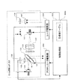
図2に、本実施の形態に係るレーザレーダの構成を示す。なお、同図では、目標値テーブル202aのデータ校正のための構成(後述)が省略されている。 FIG. 2 shows the configuration of the laser radar according to the present embodiment. In the figure, a configuration (described later) for data calibration of the target value table 202a is omitted.
図示のように、レーザレーダは、ビーム照射ヘッド201と、制御処理部202と、アクチュエータ駆動部203と、レーザ駆動部204と、を備えている。
As illustrated, the laser radar includes a beam irradiation head 201, a
ビーム照射ヘッド201は、前方空間に設定された走査領域においてレーザ光を走査させる。図示のように、ビーム照射ヘッド201は、ミラーアクチュエータ100の他に、半導体レーザ101と、コリメートレンズ102と、収差板103と、半導体レーザ104と、集光レンズ105と、PSD106と、受光レンズ107と、PD(Photo Detector)108を備えている。
The beam irradiation head 201 scans the laser beam in the scanning region set in the front space. As shown in the figure, in addition to the
走査用の半導体レーザ101は、図2のX軸方向にレーザ光(以下、「走査用レーザ光」という)を出射する。出射された走査用レーザ光は、コリメートレンズ102によって平行光に変換され、さらに、収差板103によって光学的に調整された後、ミラーアクチュエータ100に支持された平板状のミラー13に入射される。
The
ミラー13に入射された走査用レーザ光は、ミラー13によって反射され、目標領域へ向かう。ミラーアクチュエータ100によってミラー13が2次元駆動されることにより、走査用レーザ光が目標領域内において2次元方向(図2のX−Y平面方向)にスキャンされる。なお、収差板103は、目標領域における走査用レーザ光の形状を調整するためのものである。収差板103に替えて、2枚のシリンドリカルレンズを組み合わせて配置しても良い。
The scanning laser light incident on the
サーボ用の半導体レーザ104は、図2のX軸方向であって走査用レーザ光と反対方向にレーザ光(以下、「サーボ用レーザ光」という)を出射する。出射されたサーボ用レーザ光は、ミラー15の反射面15bによって反射された後、集光レンズ105によってPSD106の受光面上に集光される。集光レンズ107は目標領域からの反射光をPD108上に集光する。PD108は、受光強度に応じた信号を制御処理部202に出力する。
The
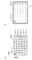
図3(a)は、PSD106の構成を示す図(側断面図)、図3(b)はPSD106の受光面を示す図である。
FIG. 3A is a diagram (side sectional view) showing the configuration of the
図3(a)に示すように、PSD106は、N型高抵抗シリコン基板の表面に、受光面と抵抗層を兼ねたP型抵抗層を形成した構造となっている。抵抗層表面には、同図(b)の横方向における光電流を出力するための電極X1、X2と、縦方向における光電流を出力するための電極Y1、Y2(同図(a)では図示省略)が形成されている。また、裏面側には共通電極が形成されている。
As shown in FIG. 3A, the
受光面にサーボ用レーザ光が照射されると、照射位置に光量に比例した電荷が発生する。この電荷は光電流として抵抗層に到達し、各電極までの距離に逆比例して分割されて、電極X1、X2、Y1、Y2から出力される。ここで、電極X1、X2、Y1、Y2から出力される電流は、サーボ用レーザ光の照射位置から各電極までの距離に逆比例して分割された大きさを有している。よって、電極X1、X2、Y1、Y2から出力される電流値をもとに、受光面上における光の照射位置を2次元的に検出することができる。 When the servo laser beam is irradiated onto the light receiving surface, an electric charge proportional to the amount of light is generated at the irradiation position. This electric charge reaches the resistance layer as a photocurrent, is divided in inverse proportion to the distance to each electrode, and is output from the electrodes X1, X2, Y1, and Y2. Here, the current output from the electrodes X1, X2, Y1, and Y2 has a magnitude divided in inverse proportion to the distance from the irradiation position of the servo laser beam to each electrode. Therefore, based on the current values output from the electrodes X1, X2, Y1, and Y2, the light irradiation position on the light receiving surface can be detected two-dimensionally.
PSD106上におけるサーボ用レーザ光の照射位置は、ミラー15の傾斜状態に応じて変位する。他方、ミラー15はミラー13と一体的に回動するため、ミラー13の回動位置とミラー15の回動位置は一対一に対応する。したがって、ミラー15で反射されたサーボ用レーザ光のPSD106受光面上における照射位置は、ミラー15の回動位置、すなわち、目標領域内における走査用レーザ光のスキャン位置に対応することとなる。
The irradiation position of the servo laser light on the
図4(a)は、目標領域における走査用レーザ光の走査状態を模式的に示す図、図4(b)は、PSD受光面上におけるサーボ用レーザ光の走査状態を模式的に示す図である。 4A is a diagram schematically illustrating a scanning state of the scanning laser light in the target region, and FIG. 4B is a diagram schematically illustrating a scanning state of the servo laser light on the PSD light receiving surface. is there.
図4(a)に示すように、走査用レーザ光は、目標領域内において、まず、最上段のライン(走査ライン1)に沿って水平方向(X軸方向)にスキャンされる。そして、このラインのスキャンが終わると、鉛直方向(Y軸方向に)に一段下のライン(走査ライン2)が水平方向にスキャンされる。このスキャン動作が、予め設定された複数段(同図では5段)に亘って繰り返される。最下段のライン(走査ライン5)に対する走査が終了すると、最上段(走査ライン1)に戻り、同様の走査が繰り返される。 As shown in FIG. 4A, the scanning laser beam is first scanned in the horizontal direction (X-axis direction) along the uppermost line (scanning line 1) in the target region. When the scanning of this line is completed, the line (scanning line 2) one step below in the vertical direction (in the Y-axis direction) is scanned in the horizontal direction. This scanning operation is repeated over a plurality of preset stages (five stages in the figure). When the scanning of the lowermost line (scanning line 5) is completed, the process returns to the uppermost stage (scanning line 1) and the same scanning is repeated.
このように走査用レーザ光が走査されると、これに伴って、サーボ用レーザ光がPSD106受光面上を走査する。すなわち、図4(b)に示すように、サーボ用レーザ光は、PSD106の受光面上において、走査用レーザ光のスキャン軌道に対応するスキャン軌道を描く。図中、点線矢印が、同図(a)の各走査ラインに対応するサーボ用レーザ光のスキャン軌道である。
When the scanning laser beam is scanned in this manner, the servo laser beam scans on the light receiving surface of the
図2に戻り、制御処理部202には、PSD106から走査用レーザ光のスキャン位置に係る電流信号が入力される。制御処理部202は、PSD106からの電流信号に基づいて、走査用レーザが目標領域内で適正なスキャン軌道(図4(a)参照)を通るように、ミラーアクチュエータ100を駆動制御する。この制御に用いるために、制御処理部202内には、目標値テーブル202aが配備されている。
Returning to FIG. 2, the current signal related to the scan position of the scanning laser beam is input from the
目標値テーブル202aには、図4(b)に示す理想軌道上の予め決められた位置(サンプル点)にサーボ用レーザ光が位置づけられたときのPSD106の出力値に基づくデータ(PSD受光面上におけるサンプル点の座標データ)が記憶されている。図5はサーボ用レーザ光の走査軌跡とサンプル点の関係を模式的に示す図である。図中、実線矢印は、走査用レーザ光が目標領域内を適正に走査するとき(図4(a)参照)の、PSD106受光面上におけるサーボ用レーザ光の理想軌道を示している。これらの座標データは、走査用レーザ光を目標領域内でスキャンするときの目標値となるものであり、予め検証等を行うことにより取得される。
The target value table 202a includes data (on the PSD light receiving surface) based on the output value of the
制御処理部202は、走査用レーザ光によるスキャン動作時、PSD106からの電流信号に基づいて、PSD受光面上のスキャン軌道が目標値テーブル202a内の座標データ(目標値)により規定される軌道に引き込まれるよう、アクチュエータ駆動部203に制御信号を出力する。アクチュエータ駆動部203は、この制御信号に基づいて、ミラーアクチュエータ100を駆動する。かかるサーボ動作によって、走査用レーザ光が目標領域内において適正な軌道でスキャンされる。
During the scanning operation by the scanning laser beam, the
また、制御処理部202は、レーザ駆動部204に対し、半導体レーザ101、104を駆動するための制御信号を出力する。レーザ駆動部204は、この制御信号に基づいて、半導体レーザ101、104を駆動する。
In addition, the
制御処理部202は、走査用レーザ光のスキャン動作時、PSD受光面上におけるサーボ用レーザ光の収束位置を監視する。そして、この収束位置が、障害物検出および距離検出を行うための位置(以下、「測距位置」という)として予め設定され位置に到達すると、このタイミングにて、半導体レーザ101の出力を一定期間だけ高パワーとする制御信号を、レーザ駆動部204に出力する。これにより、各測距位置において、半導体レーザ101からパルス状の高パワーのレーザ光(以下、「パルスレーザ光」という)が出射される。
The
このパルスレーザ光が障害物で反射され、PD108により受光されると、これに基づく電気信号が制御処理部202に入力される。これにより、制御処理部202は、障害物が存在することを検出する。また、制御処理部202は、パルスレーザ光の出射タイミングとPD108による受光タイミングとに基づいて、障害物までの距離を測定する。
When this pulsed laser beam is reflected by an obstacle and received by the
ところで、PSD106からの出力値は、温度変化や経年変化の影響を受け易い。すなわち、サーボ用レーザ光がPSD受光面上の同じ位置に収束しても、PSD106の温度が異なることによって、出力値がばらつく惧れがある。また、機器の使用期間が長くなると、同じ温度条件であっても、PSD106からの出力値が初期動作時の値からずれてくる惧れがある。これらの要因により、同じ収束位置におけるPSD106の出力値が、目標値テーブル202aの座標データを取得したときと実際のスキャン動作時とで異なることが想定され得る。しかし、こうなると、PSD106の出力値と目標値テーブル202aの座標データとを用いたサーボ動作が適正に行われなくなってしまう。
By the way, the output value from the
そこで、本実施の形態では、温度変化や経年変化等によってPSD106の出力値にズレが生じた可能性がある場合に、目標値テーブル202aの座標データを現状に合うよう校正し、校正後の目標値テーブル202aを用いてサーボ動作を行うようにしている。
Therefore, in the present embodiment, when there is a possibility that the output value of the
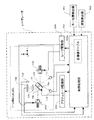
図6は、レーザレーダにおける、目標値テーブル202aのデータ校正を行うための構成を示す図である。なお、同図では、前述の目標領域をスキャンするための構成が省略されている。 FIG. 6 is a diagram showing a configuration for performing data calibration of the target value table 202a in the laser radar. In the figure, the configuration for scanning the target area is omitted.
ビーム照射ヘッド201には、上述した構成のほか、温度検出器109と、校正用の半導体レーザ110と、第1の受光器111と、第2の受光器112が備えられている。
In addition to the configuration described above, the beam irradiation head 201 includes a
温度検出器109はPSD106の近傍に配されている。この温度検出器109によって、PSD106の周辺温度を検出することにより、PSD106、特にその受光面の温度が間接的に検出される。温度検出器109による検出信号は、制御処理部202に入力される。
The
第1、第2の受光器111、112は、それぞれ、前記ミラーアクチュエータ100に設定された座標データ校正用の2つの基準位置(第1基準位置、第2基準位置)を検出するためのものである。第1、第2の受光器111、112は、ミラー15の反射面15aに対し、図6のZ軸方向に所定距離を有して配置されている。また、第1、第2の受光器111、112は、図7に示すように、図6のZ軸方向からミラーアクチュエータ100を見たときに、ミラー15を挟んで対角の位置に配置されている。第1、第2の受光器111、112は、乗用車の走行時の振動などで容易に動いてしまわないよう、ビーム照射ヘッド201の筐体(図示せず)などにネジ止め、UV接着などによって強固に固定されている。第1、第2の受光器111、112は、受光面にて受光される光の強さに応じた電気信号を出力する。この電気信号は、制御処理部202に入力される。
The first and second
目標値テーブル202a設定時の状態(以下、「初期状態」という)のもとで、アクチュエータ100が第1基準位置に駆動されると、サーボ用レーザ光は、図8(a)に示す第1基準点R1の位置に照射され、また、アクチュエータ100が第2基準位置に駆動されると、サーボ用レーザ光は、図8(a)に示す第2基準点R2の位置に照射される。第1基準点R1と第2基準点R2は、PSD106の受光面上のほぼ矩形のスキャン領域に対し、ほぼ対角の位置となる。目標値テーブル202aには、上記スキャン制御のための座標データの他に、第1基準点R1および第2基準点R2に対応する座標データが記憶されている。
When the
図6に戻り、半導体レーザ110は、レーザ駆動部204により駆動される。半導体レーザ110からは、図6のZ軸方向であって、サーボ用レーザ光の出射方向と反対方向にレーザ光(以下、「位置検出用レーザ光」という)が出射される。出射された位置検出用レーザ光は、ミラー15の反射面15aによって反射される。
Returning to FIG. 6, the
ミラーアクチュエータ100が第1基準位置に来ると、反射面15aにて反射された位置検出用レーザ光は第1の受光器111に入射し、第1の受光器111における受光量が最大となる。また、ミラーアクチュエータ100が第2基準位置に来ると、反射面15aにて反射された位置検出用レーザ光は第2の受光器112に入射し、第2の受光器112における受光量が最大となる。すなわち、第1、第2の位置検出器111、112の受光量が最大になることを検出することで、ミラーアクチュエータ100(ミラー13およびミラー15)の第1基準位置、第2基準位置がそれぞれ検出される。
When the
座標データの校正時には、制御処理部202は、半導体レーザ104、110を駆動させるとともに、ミラーアアクチュエータ100を第1基準位置の近傍域で2次元的に駆動させる。これにより、PSD106の受光面上では、第1基準点R1の近傍域でサーボ用レーザ光がスキャンされる。制御処理部202は、このスキャン動作中に第1の受光器111で受光量が最大となったときのPSD106の出力値(座標データ)を記憶する。
When the coordinate data is calibrated, the
次に、制御処理部202は、第2基準位置の近傍域でミラーアクチュエータ100を駆動させ、同様に、サーボ用レーザ光を第2基準点R2の近傍でスキャンさせる。そして、このスキャン動作中に第2の受光器112で受光量が最大となったときのPSD106の出力値(座標データ)を記憶する。
Next, the
実動作時におけるPSD106の状態が初期状態と同じであれば、このようにして校正動作時に記憶された2つの座標データは、第1基準点R1、第2基準点R2の座標データと等しくなる。よって、この場合、制御処理部202は、目標値テーブル202aの座標データの校正を行わない。
If the state of the
一方、温度変化や経年変化等の影響を受けることにより、PSD106の状態が初期状態から変化した場合には、校正動作時に記憶された2つの座標データは、第1基準点R1、第2基準点R2の座標データと異なるものとなる。つまり、校正時に記憶された2つの座標データに対応する座標点を、それぞれ、第1基準点R1´および第2基準点R2´とすると、図8(b)に示すように、第1基準点R1´および第2基準点R2´は、第1基準点R1、第2基準点R2からずれるものとなる。この場合、制御処理部202は、以下と等価な処理を行うことによって目標値テーブル202aを校正し、校正後の目標値テーブルを用いてサーボ動作を行う。
On the other hand, when the state of the
すなわち、第1基準点R1´と第1基準点R1との間の水平方向のズレ量ΔP1と鉛直方向のズレ量ΔQ1を算出するとともに、第2基準点R2´と第1基準点R2との間の水平方向のズレ量ΔP2と鉛直方向のズレ量ΔQ2を算出する。次に、水平方向のズレ量の平均値(ΔP1+ΔP2)/2、および鉛直方向のズレ量の平均値(ΔQ1+ΔQ2)/2を求め、これらを補正値として目標値テーブル202aの各座標データに加算して新たな目標値テーブル202aを生成する。そして、生成後の目標値テーブル202aを用いてサーボ動作を行う。 That is, the horizontal shift amount ΔP1 and the vertical shift amount ΔQ1 between the first reference point R1 ′ and the first reference point R1 are calculated, and the second reference point R2 ′ and the first reference point R2 are calculated. A horizontal shift amount ΔP2 and a vertical shift amount ΔQ2 are calculated. Next, an average value of the deviation amount in the horizontal direction (ΔP1 + ΔP2) / 2 and an average value of the deviation amount in the vertical direction (ΔQ1 + ΔQ2) / 2 are obtained, and these are added as correction values to each coordinate data of the target value table 202a. A new target value table 202a is generated. Then, the servo operation is performed using the generated target value table 202a.
このように、温度変化や経年変化等に合わせて目標値テーブル202a内の座標データを校正し、校正後の目標値テーブルをサーボ動作に用いることにより、温度変化や経年変化等によらず、精度の高いサーボ動作を行うことができる。 As described above, the coordinate data in the target value table 202a is calibrated in accordance with the temperature change, aging change, etc., and the calibrated target value table is used for the servo operation. High servo operation can be performed.
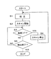
本実施の形態において、目標値テーブル202aの校正動作は、図9に示すフローチャートに従って行われ得る。なお、以下の動作は、制御処理部202における処理制御のもとで行われる。
In the present embodiment, the calibration operation of the target value table 202a can be performed according to the flowchart shown in FIG. The following operation is performed under process control in the
レーザレーダにおいて障害物の検出動作が開始されると、まず、上記図8(b)を参照して説明した如くして、目標値テーブル202aのデータ校正が行われる(S1)。かかるデータ校正が終了すると、目標領域内における走査用レーザ光のスキャン動作が開始される(S2)。このスキャン動作は、S1において校正された目標値テーブルを用いて行われる。 When the obstacle detection operation is started in the laser radar, first, data correction of the target value table 202a is performed as described with reference to FIG. 8B (S1). When such data calibration is completed, the scanning operation of the scanning laser beam in the target area is started (S2). This scanning operation is performed using the target value table calibrated in S1.
スキャン動作中、温度検出器109からの検出信号をもとにPSD106の温度が監視される。すなわち、温度検出器109により検出された温度が、スキャン動作開始時の温度から、予め設定された温度T(たとえば、50℃、60℃、70℃、…)を超えたか否かが判断される(S3)。検出温度が設定温度Tを超えていなければ(S3:NO)、他の要因(電源OFF等)によってスキャン動作が終了されない限り(S5:NO)、スキャン動作が継続される。
During the scanning operation, the temperature of the
一方、温度検出器109における検出温度が設定温度T(たとえば、50℃)を超えたと判断されると(S3:YES)、スキャン動作が停止され(S4)、再び目標値テーブルのデータ校正が行われる(S1)。データ校正が終了すると、校正後の目標値テーブルをもとに、スキャン動作が再開される(S2)。
On the other hand, if it is determined that the temperature detected by the
その後、引き続きPSD106の温度が監視される。そして、温度検出器109の検出温度が次の設定温度T(たとえば、60℃)を超えたか否かが判断される(S3)。検出温度が次の設定温度Tを超えたと判断されると(S3:YES)、上記と同様に、スキャン動作が停止され(S4)、目標値テーブルのデータ校正が行われ(S1)、校正後の目標値テーブルをもとに、スキャン動作が再開される(S2)。
Thereafter, the temperature of the
スキャン動作中に、スキャン動作を終了すべき他の要因が生じると(S5:YES)、スキャン動作が停止され、障害物の検出動作が終了する。 If another factor for ending the scan operation occurs during the scan operation (S5: YES), the scan operation is stopped and the obstacle detection operation is ended.
以上、上記実施の形態では、PSD106の出力値が、温度変化や経年変化などによって変化する状況となった場合に、ミラーアクチュエータ100のサーボ動作に利用される目標値テーブル202aの座標データを、PSD106の出力値の変化に応じて校正するようにしたので、精度の高いサーボ動作を行うことができる。これにより、走査用レーザ光による目標領域内でのスキャン動作を精度よく行うことできる。
As described above, in the above-described embodiment, when the output value of the
さらに、ミラーアクチュエータ100の第1基準位置および第2基準位置を、半導体レーザ110(半導体レーザ101)と第1、第2の受光器111、112を用いて検出するようにしているので、ミラーアクチュエータ100と非接触状態で検出を行うことができ、ミラーアクチュエータ100に余計な負荷がかかるのを防止できる。
Further, since the first reference position and the second reference position of the
さらに、本実施の形態では、障害物の検出動作が起動される度に、データ校正を行うようにしているので、経年変化によるスキャン動作の精度劣化を一層防止できる。 Furthermore, in this embodiment, data calibration is performed each time an obstacle detection operation is started, so that it is possible to further prevent deterioration in accuracy of the scanning operation due to secular change.
さらに、本実施の形態では、温度検出器109による検出温度が、SD106の出力値が影響を受けるような温度になった場合にデータ校正を行う構成としたので、的確なタイミングでデータ校正を行うことができる。よって、温度変化によるスキャン動作の精度劣化を防止しつつ、障害物検出のために行われるスキャン動作がデータ校正のために頻繁に中断されることを防止でき、安全性を確保することができる。
Furthermore, in the present embodiment, since the data calibration is performed when the temperature detected by the
なお、PSD106における出力変動は、受光面上の全ての位置において一様ではなく、通常、位置毎に変動の仕方が相違する可能性が高い。よって、目標値テーブル202aの校正は、かかる変動のばらつきを考慮して、なるべく多くの基準点を受光面上に設定し、各基準点における変動値(図8(b)のΔP1、ΔQ1およびΔP2、ΔQ2)の平均値等をもとに行うのが望ましいとも考えられる。しかし、多数の基準点を受光面上に設定すると、それに応じてアクチュエータ100の基準位置も増加し、その結果、各基準点を検出するための光検出器の配置数も増加する。このため、受光面上に設定する基準点をあまり多くすると、部品点数が増加し、構成の複雑化とコストの上昇を招くこととなる。
Note that output fluctuations in the
これに対し、本実施の形態では、PSD106の受光面上の対角となる2つの位置に第1基準点R1と第2基準点R2を設定し、これら基準点において出力値の変化を検出するようにしたので、検出点をできる限り少なくして光検出器などの部品が増加するのを抑えつつ、受光面上の位置による出力値の変化のバラツキを考慮した校正処理を行うことができる。
In contrast, in the present embodiment, the first reference point R1 and the second reference point R2 are set at two diagonal positions on the light receiving surface of the
なお、本実施の形態のレーザレーダは、たとえば、乗用車等の移動体に搭載することができる。 In addition, the laser radar of this Embodiment can be mounted in moving bodies, such as a passenger car, for example.
図10は、乗用車にレーザレーダを搭載した場合の構成を示す図である。制御処理部202には、乗用車側に備えられたキー位置検出器301および速度検出器302から検出信号が入力される。キー位置検出器301は、エンジンを始動するためのイグニッションキーがエンジンを始動する位置にあるか否か検出するものである。イグニッションキーがエンジンを始動する位置に来れば、エンジンが始動したと判断できる。速度検出器302は乗用車の速度を検出するものである。
FIG. 10 is a diagram showing a configuration when a laser radar is mounted on a passenger car. Detection signals are input to the
図11は、レーザレーダが乗用車に搭載された場合における校正動作の一例を示すフローチャートである。なお、以下の動作は、制御処理部202における処理制御のもとで行われる。
FIG. 11 is a flowchart showing an example of the calibration operation when the laser radar is mounted on a passenger car. The following operation is performed under process control in the
キー位置検出器301からの入力に基づいて、乗用車のエンジンが始動したか否かが判断される(S11)。エンジンが始動したと判断されると、障害物の検出動作が開始される。
Based on the input from the
まず、上記図8(b)を参照して説明した如くして、目標値テーブル202aのデータ校正が行われる(S12)。かかるデータ校正が終了すると、スキャン動作が開始される(S13)。このスキャン動作は、S12において校正された目標値テーブルを用いて行われる。 First, as described with reference to FIG. 8B, data correction of the target value table 202a is performed (S12). When the data calibration is completed, a scanning operation is started (S13). This scanning operation is performed using the target value table calibrated in S12.
次に、温度検出器109により検出された温度が、スキャン動作開始時の温度から、予め設定された温度T(たとえば、50℃、60℃、70℃、…)を超えたか否かが判断される(S14)。そして、検出温度が設定温度T(たとえば、50℃)を超えたと判断されると(S14:YES)、速度検出器302からの入力に基づいて、乗用車の速度が停止したか否かが判断される(S15)。乗用車が走行していれば(S15:NO)、目標値テーブル202aのデータ校正が行われずにそのまま待機される。
Next, it is determined whether or not the temperature detected by the
乗用車が信号待ちで一時停止するなどして乗用車が停止すると(S15:YES)、スキャン動作が停止され(S16)、目標値テーブル202aのデータ校正が再び行われる(S12)。データ校正が終了すると、校正後の目標値テーブルをもとに、スキャン動作が再開される(S13)。 When the passenger car stops, for example, temporarily stops waiting for a signal (S15: YES), the scanning operation is stopped (S16), and data calibration of the target value table 202a is performed again (S12). When the data calibration is completed, the scanning operation is restarted based on the target value table after calibration (S13).
その後、引き続きPSD106の温度が監視される。そして、温度検出器109の検出温度が、次の設定温度T(たとえば、60℃)を超えたと判断されると(S14:YES)、上記と同様に、速度停止(S15:YES)を待って、スキャン動作が停止され(S16)、データ校正が行われる(S12)。
Thereafter, the temperature of the
スキャン動作の間、キー位置検出器301からの入力に基づいて、エンジンが停止されたか否かが判断される(S17)。エンジンが停止したと判断されると(S17:YES)、スキャン動作が停止され、障害物の検出動作が終了される。 During the scanning operation, it is determined whether or not the engine is stopped based on the input from the key position detector 301 (S17). If it is determined that the engine has stopped (S17: YES), the scanning operation is stopped and the obstacle detection operation is ended.
このように、図11のフローチャートでは、エンジンを始動する度、すなわち、障害物の検出動作を起動する度に目標値テーブルのデータ校正が行われるので、経年変化によるサーボ動作の精度劣化を防止できる。 As described above, in the flowchart of FIG. 11, since the data calibration of the target value table is performed every time the engine is started, that is, every time the obstacle detection operation is started, it is possible to prevent deterioration in the accuracy of the servo operation due to secular change. .
また、図11のフローチャートでは、PSD106の出力値が影響を受けるような温度になるとデータ校正が行われるので、温度変化によるサーボ動作の精度劣化を防止できる。
In the flowchart of FIG. 11, data calibration is performed at a temperature at which the output value of the
さらに、図11のフローチャートでは、速度停止がなされなければデータ校正が行われないので、乗用車の走行中に、校正動作によって障害物検出のためのスキャン動作が中断されるようなことがなく、安全性が確保される。 Further, in the flowchart of FIG. 11, since the data calibration is not performed unless the speed is stopped, the scanning operation for detecting the obstacle is not interrupted by the calibration operation while the passenger car is running, and the safety is ensured. Sex is secured.
次に、ビーム照射ヘッド201の変更例につき、図12を参照して説明する。この変更例では、図12(a)に示すように、ミラーアクチュエータ100において、ミラー15に変えて、屈折素子50が設けられている。この屈折素子50は、例えば、アクリルやガラスでできている。集光レンズ105およびPSD106は、この屈折素子50を挟んで、半導体レーザ104の反対側に配置されている。
Next, a modified example of the beam irradiation head 201 will be described with reference to FIG. In this modified example, as shown in FIG. 12A, in the
半導体レーザ104から出射されたサーボ用レーザ光は、屈折素子50に入射され、同図(a)に示すように、屈折素子50の屈折作用を受ける。その後、屈折素子50を通過したサーボ用レーザ光は、集光レンズ105を介してPSD106に受光される。このとき、屈折素子50が回動すると、屈折作用によってPSD106への照射位置が変位する。
The servo laser light emitted from the
また、この変更例においては、同図(b)に示すように、校正用の半導体レーザとして、走査用の半導体レーザ101が兼用される。この場合、第1の受光器111および第2の受光器112は、図13に示すように、図12(b)のZ軸方向からミラーアクチュエータ100を見たときに、ミラー13を挟んで対角の位置に配置される。ここで、第1の受光器111および第2の受光器112は、障害物検出の際に走査用レーザ光を目標領域内で走査しても、走査用レーザ光を遮ることのない位置に配されている。
In this modified example, as shown in FIG. 5B, the
半導体レーザ101は、図6における校正用の半導体レーザ110に比べて出射パワーがかなり大きい。このような高パワーのレーザ光が第1、第2の受光器111、112にそのまま入射されてしまうと、第1、第2の受光器111、112が破損してしまう惧れがある。そこで、第1、第2の受光器111、112における受光面の前には、それぞれ、レーザ光を減衰させるフィルタ113、114が配されている。こうして、校正動作の際には、半導体レーザ101からのレーザ光が位置検出用レーザ光として利用される。当然ながら、校正動作時における半導体レーザ101の出射パワーは、目標領域を走査する際の出射パワーに対し可能な限り低く抑えるのが望ましい。
The
このように、走査用の半導体レーザ101を、校正用の半導体レーザ110として兼用できるようにすれば、構成の簡素化を図ることができる。
In this way, if the
以上、本発明の実施形態について説明したが、本発明は、上記実施の形態によって制限されるものではなく、また、本発明の実施形態も、上記以外に種々の変更が可能である。 Although the embodiments of the present invention have been described above, the present invention is not limited to the above-described embodiments, and the embodiments of the present invention can be variously modified in addition to the above.
例えば、上記実施の形態では、目標値テーブル202aのデータ校正に利用する第1基準点R1と第2基準点R2を、図8(a)に示す如く、障害物検出動作時におけるサーボ用レーザ光の軌道領域外に設定したが、これら基準点をサーボ用レーザ光の軌道領域内に設定するようにしてもよい。但し、上記図12に示す変更例では、障害物検出の際に走査用レーザ光を遮ることのない位置に第1、第2の受光器111、112を配置する必要があり、これに応じて、PSD受光面上における基準点を設定する必要がある。この理由から、この変更例においては、第1基準点R1と第2基準点R2は、必然的に、サーボ用レーザ光の軌道領域外に設定されることとなる。
For example, in the above embodiment, the first reference point R1 and the second reference point R2 used for data calibration of the target value table 202a are set as the servo laser light during the obstacle detection operation as shown in FIG. However, these reference points may be set within the orbital region of the servo laser beam. However, in the modified example shown in FIG. 12, it is necessary to arrange the first and second
また、上記実施の形態では、ミラーアクチュエータ100の第1基準位置および第2基準位置を、校正用の半導体レーザ110(または、半導体レーザ101を兼用)と第1、第2の受光器111、112を用いて検出するようにしたが、たとえば、マイクロスイッチによる非接触式の検出スイッチなど、他の検出器によってこれら基準位置を検出するようにしてもよい。
In the above-described embodiment, the first reference position and the second reference position of the
さらに、上記図11の構成例では、キー位置検出器301からの信号によりエンジンの始動を判断し、速度検出器302からの信号により速度停止を判断する構成としたが、その他、例えば、乗用車側の制御部からエンジン始動の情報、速度停止の情報をもらうような構成としてもよい。
Furthermore, in the configuration example of FIG. 11 described above, the engine start is determined based on the signal from the
さらに、上記図11の構成例では、乗用車のエンジンの始動を検出してデータ校正を行う構成としているが、検出動作を起動するタイミングでデータ校正を行うように校正してよく、例えば、レーザレーダ自身に電源が投入されたタイミングでデータ校正を行う構成とすることも可能である。 Further, in the configuration example of FIG. 11 described above, the data calibration is performed by detecting the start of the passenger car engine. However, the calibration may be performed so that the data calibration is performed at the timing of starting the detection operation. It is also possible to adopt a configuration in which data calibration is performed at the timing when the power is turned on.
さらに、上記実施の形態では、温度検出器109によって、PSD106の周辺温度を検出することで、PSD106の温度を間接的に検出するようにしている。これは、上記実施の形態においては、PSD106に温度検出器109を直接取り付けて直接的に温度を検出することが難しいためである。しかし、可能であれば、PSD106に温度検出器109を直接取り付けて、直接的に温度を検出するようにしてもよく、また、被接触式の温度検出器を用いて直接的に温度を検出するようにしてもよい。PSD106の温度を検出する方法としては、その他、種々の方法が取られ得る。
Further, in the above embodiment, the temperature of the
さらに、上記実施の形態は、車載用のレーザレーダに本発明を適用したものであったが、本発明は、たとえば、大気中のエアロゾル計測用など、他の用途のレーザレーダに適用することも可能である。また、上記実施の形態では、サーボやデータ校正に用いるレーザ光を出射する光源として半導体レーザを用いたが、これに代えて、LED(Light Emitting Diode)等、他の光源を用いることもできる。 Furthermore, although the above-described embodiment is an application of the present invention to an in-vehicle laser radar, the present invention can also be applied to a laser radar for other uses, for example, for measuring aerosol in the atmosphere. Is possible. In the above embodiment, a semiconductor laser is used as a light source for emitting laser light used for servo and data calibration. However, other light sources such as an LED (Light Emitting Diode) may be used instead.
この他、本発明の実施の形態は、特許請求の範囲に示された技術的思想の範囲内において、適宜、種々の変更が可能である。 In addition, the embodiment of the present invention can be variously modified as appropriate within the scope of the technical idea shown in the claims.
13 ミラー(検出光変位部)
15 ミラー(サーボ光変位部、検出光変位部)
50 屈折素子(サーボ光変位部)
100 ミラーアクチュエータ(アクチュエータ)
101 半導体レーザ(光源)
106 PSD(受光位置検出器)
109 温度検出器(温度検出部)
110 半導体レーザ(位置検出用光源)
111 第1の受光器
112 第2の受光器
113 フィルタ
114 フィルタ
202 制御処理部(駆動制御部、軌道情報校正部)
202a 目標値テーブル(軌道情報記憶部、基準位置記憶)
13 Mirror (Detection light displacement part)
15 Mirror (servo light displacement part, detection light displacement part)
50 Refraction element (servo light displacement part)
100 mirror actuator (actuator)
101 Semiconductor laser (light source)
106 PSD (light receiving position detector)
109 Temperature detector (temperature detector)
110 Semiconductor laser (position detection light source)
DESCRIPTION OF
202a Target value table (trajectory information storage unit, reference position storage)
Claims (6)
前記アクチュエータを駆動制御する駆動制御部と、
前記アクチュエータの駆動に伴ってサーボ光の進行方向を変化させるサーボ光変位部と、
前記サーボ光を受光して受光位置に応じた信号を出力する受光位置検出器と、
前記走査レーザ光が目標領域内を適正に走査するときの前記受光位置検出器上における前記サーボ光の理想軌道に関する軌道情報を記憶する軌道情報記憶部と、
前記アクチュエータが予め設定された特定位置に位置づけられたときの前記受光位置検出器上における前記サーボ光の基準受光位置に関する参照情報を記憶する基準位置記憶部と、
前記アクチュエータが前記特定位置にあることを検出する特定位置検出部と、
前記特定位置検出部によって前記アクチュエータが前記特定位置にあることが検出されたときの前記受光位置検出器からの出力信号と前記基準位置記憶部に記憶された前記参照情報に基づいて前記軌道情報を現状に適合するよう校正する軌道情報校正部とを備え、
前記駆動制御部は、前記受光位置検出器からの出力信号と前記軌道情報校正部にて校正された前記軌道情報に基づいて前記走査レーザ光が前記目標領域内を走査するよう前記アクチュエータを制御する、
ことを特徴とするビーム照射装置。 An actuator for scanning a scanning laser beam in a two-dimensional direction;
A drive control unit for driving and controlling the actuator;
A servo light displacement unit that changes a traveling direction of the servo light in accordance with driving of the actuator;
A light receiving position detector that receives the servo light and outputs a signal corresponding to the light receiving position;
A trajectory information storage unit that stores trajectory information related to the ideal trajectory of the servo light on the light receiving position detector when the scanning laser light appropriately scans the target area;
A reference position storage unit that stores reference information related to a reference light receiving position of the servo light on the light receiving position detector when the actuator is positioned at a predetermined specific position;
A specific position detector for detecting that the actuator is at the specific position;
Based on an output signal from the light receiving position detector when the specific position detecting unit detects that the actuator is at the specific position and the reference information stored in the reference position storage unit, the trajectory information is obtained. It has a track information calibration section that calibrates it to the current situation,
The drive control unit controls the actuator so that the scanning laser beam scans the target area based on an output signal from the light receiving position detector and the trajectory information calibrated by the trajectory information calibration unit. ,
A beam irradiation apparatus characterized by that.
前記特定位置検出部は、第1の特定位置および第2の特定位置を検出し、
前記第1の特定位置および第2の特定位置は、前記アクチュエータがこれら特定位置にあるときの前記受光位置検出器上における前記サーボ用レーザ光の受光位置が前記受光位置検出器の受光面上においてほぼ対角の位置となるよう設定されている、
ことを特徴とするビーム照射装置。 The beam irradiation apparatus according to claim 1,
The specific position detector detects a first specific position and a second specific position;
The first specific position and the second specific position are such that the light receiving position of the servo laser beam on the light receiving position detector when the actuator is at the specific position is on the light receiving surface of the light receiving position detector. Set to be almost diagonal,
A beam irradiation apparatus characterized by that.
前記特定位置検出部は、
位置検出光を発光する位置検出用光源と、
前記アクチュエータの駆動に伴って前記位置検出光の進行方向を変化させる検出光変位部と、
前記アクチュエータが前記第1の特定位置にあるときに前記位置検出光を受光する第1の受光器と、
前記アクチュエータが前記第2の特定位置にあるときに前記位置検出光を受光する第2の受光器とを含む、
ことを特徴とするビーム照射装置。 The beam irradiation apparatus according to claim 2, wherein
The specific position detector is
A position detection light source that emits position detection light;
A detection light displacement section that changes a traveling direction of the position detection light in accordance with driving of the actuator;
A first light receiver for receiving the position detection light when the actuator is at the first specific position;
A second light receiver that receives the position detection light when the actuator is in the second specific position;
A beam irradiation apparatus characterized by that.
前記走査レーザ光を出射する光源を前記位置検出用光源として兼用するとともに前記第1受光器および第2受光器の前段に光強度を減衰させるフィルタを配した、
ことを特徴とするビーム照射装置。 In the beam irradiation apparatus of Claim 3,
A light source that emits the scanning laser light is also used as the position detection light source, and a filter that attenuates light intensity is disposed in front of the first light receiver and the second light receiver.
A beam irradiation apparatus characterized by that.
前記受光位置検出器の温度を検出する温度検出部を備え、
前記駆動制御部は、前記温度検出部によって検出された温度が予め設定された温度になったときに前記アクチュエータを前記特定位置の近傍範囲において駆動させ、
前記軌道情報校正部は、当該近傍範囲における前記アクチュエータの駆動に応じて前記軌道情報の校正を行う、
ことを特徴とするビーム照射装置。 In the beam irradiation apparatus of any one of Claim 1 to 4,
A temperature detector for detecting the temperature of the light receiving position detector;
The drive control unit drives the actuator in the vicinity of the specific position when the temperature detected by the temperature detection unit reaches a preset temperature,
The trajectory information calibration unit calibrates the trajectory information according to the driving of the actuator in the vicinity range.
A beam irradiation apparatus characterized by that.
前記駆動制御部は、当該ビーム照射装置を搭載する移動体の速度情報を参照し、前記移動体が移動状態にあるときは前記走査レーザ光が前記目標領域内を走査するよう前記アクチュエータを制御し、前記移動体が停止状態にあるときに前記アクチュエータを前記特定位置の近傍範囲において駆動させ、
前記軌道情報校正部は、当該近傍範囲における前記アクチュエータの駆動に応じて前記軌道情報の校正を行う、
ことを特徴とするビーム照射装置。 In the beam irradiation apparatus of any one of Claim 1 to 5,
The drive control unit refers to speed information of a moving body on which the beam irradiation device is mounted, and controls the actuator so that the scanning laser beam scans the target area when the moving body is in a moving state. Driving the actuator in the vicinity of the specific position when the moving body is in a stopped state;
The trajectory information calibration unit calibrates the trajectory information according to the driving of the actuator in the vicinity range.
A beam irradiation apparatus characterized by that.
Priority Applications (1)
| Application Number | Priority Date | Filing Date | Title |
|---|---|---|---|
| JP2007299713A JP2009128014A (en) | 2007-11-19 | 2007-11-19 | Beam irradiation apparatus |
Applications Claiming Priority (1)
| Application Number | Priority Date | Filing Date | Title |
|---|---|---|---|
| JP2007299713A JP2009128014A (en) | 2007-11-19 | 2007-11-19 | Beam irradiation apparatus |
Publications (1)
| Publication Number | Publication Date |
|---|---|
| JP2009128014A true JP2009128014A (en) | 2009-06-11 |
Family
ID=40819120
Family Applications (1)
| Application Number | Title | Priority Date | Filing Date |
|---|---|---|---|
| JP2007299713A Withdrawn JP2009128014A (en) | 2007-11-19 | 2007-11-19 | Beam irradiation apparatus |
Country Status (1)
| Country | Link |
|---|---|
| JP (1) | JP2009128014A (en) |
Cited By (5)
| Publication number | Priority date | Publication date | Assignee | Title |
|---|---|---|---|---|
| JP2014228783A (en) * | 2013-05-24 | 2014-12-08 | 株式会社リコー | Optical scanner, image forming apparatus, and image projection device |
| JP2016048211A (en) * | 2014-08-28 | 2016-04-07 | 株式会社リコー | Optical scanning device, object detection device, and sensing device |
| JP2016161533A (en) * | 2015-03-05 | 2016-09-05 | 株式会社リコー | Semiconductor laser drive device, optical scanning device, object detection device and moving body device |
| JP2021038940A (en) * | 2019-08-30 | 2021-03-11 | 住友重機械工業株式会社 | Shape measuring device, reference device and calibration method of detector |
| CN113866969A (en) * | 2021-10-25 | 2021-12-31 | 航天科工微电子系统研究院有限公司 | Light path system for light beam tracking and aiming equipment |
-
2007
- 2007-11-19 JP JP2007299713A patent/JP2009128014A/en not_active Withdrawn
Cited By (7)
| Publication number | Priority date | Publication date | Assignee | Title |
|---|---|---|---|---|
| JP2014228783A (en) * | 2013-05-24 | 2014-12-08 | 株式会社リコー | Optical scanner, image forming apparatus, and image projection device |
| JP2016048211A (en) * | 2014-08-28 | 2016-04-07 | 株式会社リコー | Optical scanning device, object detection device, and sensing device |
| JP2016161533A (en) * | 2015-03-05 | 2016-09-05 | 株式会社リコー | Semiconductor laser drive device, optical scanning device, object detection device and moving body device |
| JP2021038940A (en) * | 2019-08-30 | 2021-03-11 | 住友重機械工業株式会社 | Shape measuring device, reference device and calibration method of detector |
| JP7296279B2 (en) | 2019-08-30 | 2023-06-22 | 住友重機械工業株式会社 | Shape measuring device and detector calibration method |
| CN113866969A (en) * | 2021-10-25 | 2021-12-31 | 航天科工微电子系统研究院有限公司 | Light path system for light beam tracking and aiming equipment |
| CN113866969B (en) * | 2021-10-25 | 2024-02-27 | 航天科工微电子系统研究院有限公司 | Light path system for light beam tracking equipment |
Similar Documents
| Publication | Publication Date | Title |
|---|---|---|
| JP5232396B2 (en) | Beam irradiation device | |
| US7773281B2 (en) | Beam irradiation apparatus | |
| US7940443B2 (en) | Laser radar and beam irradiation apparatus therefor | |
| JP2009014698A (en) | Beam irradiation device and laser radar | |
| JP2009128014A (en) | Beam irradiation apparatus | |
| JP2008225285A (en) | Beam radiation apparatus | |
| JP2009014639A (en) | Beam radiation unit and laser radar | |
| JP4484835B2 (en) | Beam irradiation device | |
| US8164078B2 (en) | Beam irradiation device | |
| US20100321751A1 (en) | Mirror actuator and beam irradiation device | |
| US7864304B2 (en) | Beam irradiation device, laser radar system, and detecting device | |
| CN110168820B (en) | Laser device | |
| JP2008299144A (en) | Beam irradiation apparatus and laser radar | |
| JP2008298686A (en) | Beam irradiation device and laser radar | |
| JP2008298652A (en) | Beam irradiation device and laser radar | |
| JP2009008606A (en) | Beam irradiation device and laser radar | |
| US8368874B2 (en) | Beam irradiation device and laser radar system | |
| JP2010025600A (en) | Beam irradiation apparatus | |
| US8345268B2 (en) | Beam irradiation device | |
| US20210149026A1 (en) | Optical distance measuring device | |
| US7601949B2 (en) | Optical scanner device | |
| JP2010048564A (en) | Beam irradiation device | |
| US20100078582A1 (en) | Beam irradiation device and position sensing device | |
| US8467043B2 (en) | Lens module testing apparatus | |
| CN114755770B (en) | Automatic dimming system and dimming method for laser coupling optical fiber |
Legal Events
| Date | Code | Title | Description |
|---|---|---|---|
| A621 | Written request for application examination |
Free format text: JAPANESE INTERMEDIATE CODE: A621 Effective date: 20101028 |
|
| A761 | Written withdrawal of application |
Free format text: JAPANESE INTERMEDIATE CODE: A761 Effective date: 20110712 |