JP2009127573A - Control device for internal combustion engine - Google Patents
Control device for internal combustion engine Download PDFInfo
- Publication number
- JP2009127573A JP2009127573A JP2007305241A JP2007305241A JP2009127573A JP 2009127573 A JP2009127573 A JP 2009127573A JP 2007305241 A JP2007305241 A JP 2007305241A JP 2007305241 A JP2007305241 A JP 2007305241A JP 2009127573 A JP2009127573 A JP 2009127573A
- Authority
- JP
- Japan
- Prior art keywords
- engine
- stop
- internal combustion
- combustion engine
- rotation
- Prior art date
- Legal status (The legal status is an assumption and is not a legal conclusion. Google has not performed a legal analysis and makes no representation as to the accuracy of the status listed.)
- Pending
Links
Images


Abstract
Description
本発明は、所定の自動停止条件が成立したときに内燃機関を自動停止させ、所定の自動始動条件が成立したときに内燃機関を自動始動させる内燃機関の制御装置に関する発明である。 The present invention relates to a control device for an internal combustion engine that automatically stops the internal combustion engine when a predetermined automatic stop condition is satisfied, and automatically starts the internal combustion engine when a predetermined automatic start condition is satisfied.
近年、車両に搭載される内燃機関においては、燃費節減、排気エミッション低減等を目的として、自動停止・始動装置(いわゆるアイドリングストップ装置)を採用したものがある。この自動停止・始動装置は、運転者が車両を停車させて所定の自動停止条件が成立したときに内燃機関を自動的に停止させ、その後、運転者が車両を発進させようとする操作を行って所定の自動始動条件が成立したときに内燃機関を自動的に再始動させるようにしている。 In recent years, some internal combustion engines mounted on vehicles employ an automatic stop / start device (so-called idling stop device) for the purpose of reducing fuel consumption and exhaust emissions. This automatic stop / start device automatically stops the internal combustion engine when the driver stops the vehicle and a predetermined automatic stop condition is satisfied, and then the driver performs an operation to start the vehicle. Thus, the internal combustion engine is automatically restarted when a predetermined automatic start condition is satisfied.
また、特許文献1(特開2001−263147号公報)に記載されているように、内燃機関のクランク軸にモータジェネレータを連結した構成のハイブリッド車において、内燃機関の自動停止の際に、内燃機関の回転に連動して回転するモータジェネレータのレゾルバの出力信号に基づいて内燃機関の逆転(クランク軸の逆回転)を検出したときや、クランク角センサからの出力信号(パルス信号)が入力されることなく所定時間(例えば1.5sec)が経過したときに、内燃機関が停止したと判定するようにしたものがある。
一般に、内燃機関に設けられたクランク角センサでは、内燃機関の逆転を検出できないため、上記特許文献1に記載されたハイブリッド車では、内燃機関の回転に連動して回転するモータジェネレータのレゾルバを、内燃機関の逆転を検出する逆転検出手段として利用するようにしているが、このような逆転検出手段として利用可能なレゾルバ等のセンサを搭載していない車両では、内燃機関の逆転を検出可能な特殊なセンサ等を新たに設ける必要があり、低コスト化の要求を満たすことができないという問題がある。
In general, since the crank angle sensor provided in the internal combustion engine cannot detect the reverse rotation of the internal combustion engine, in the hybrid vehicle described in
また、上記特許文献1のように、クランク角センサからの出力信号が入力されることなく所定時間(例えば1.5sec)が経過したときに内燃機関が停止したと判定する停止判定システムでは、内燃機関が実際に停止しても、クランク角センサからの出力信号が入力されない状態が所定時間継続するまで待たないと、内燃機関の停止が検出されないため、内燃機関の実際の停止タイミングに対して停止検出タイミングが遅れてしまうという問題がある。
Further, as in
また、内燃機関の停止を検出してから自動始動を開始するシステムでは、内燃機関の実際の停止タイミングに対して停止検出タイミングの遅れが大きいと、自動停止の際に内燃機関の回転が停止する前に運転者の発進操作等によって自動始動要求が発生した場合に、自動始動要求が発生してから自動始動を開始するまでの遅れが大きくなってしまい、運転者に違和感(自動始動のもたつき感)を感じさせてしまうという問題がある。 In addition, in a system in which the automatic start is started after detecting the stop of the internal combustion engine, if the delay of the stop detection timing is large with respect to the actual stop timing of the internal combustion engine, the rotation of the internal combustion engine stops during the automatic stop. When an automatic start request is generated by the driver's start operation, etc., the delay between the start of the automatic start request and the start of the automatic start becomes large, and the driver feels uncomfortable ).
本発明は、このような事情を考慮してなされたものであり、従って本発明の目的は、内燃機関の自動停止の際に内燃機関の停止を速やかに検出できると共に、低コスト化の要求を満たすことができる内燃機関の制御装置を提供することにある。 The present invention has been made in view of such circumstances. Accordingly, the object of the present invention is to detect the stop of the internal combustion engine quickly when the internal combustion engine is automatically stopped, and to reduce the cost. An object of the present invention is to provide a control device for an internal combustion engine that can be satisfied.
上記目的を達成するために、請求項1に係る発明は、所定の自動停止条件が成立したときに内燃機関を自動停止させ、所定の自動始動条件が成立したときに内燃機関を自動始動させる内燃機関の制御装置において、内燃機関の自動停止の際に内燃機関の回転速度が低下する過程で所定回転速度を通過するときのクランク角に基づいて内燃機関の回転が停止するまでに要する時間に相当する停止判定時間を停止判定時間算出手段により算出し、内燃機関の自動停止の際に内燃機関の回転速度が所定回転速度を通過してから停止判定時間が経過したときに内燃機関の回転が停止したと停止判定手段により判定するようにしたものである。
In order to achieve the above object, an invention according to
本発明者の実験結果によれば、内燃機関が停止する際に内燃機関の回転速度が低下する過程で所定回転速度を通過するときのクランク角と、内燃機関の回転速度が所定回転速度を通過してから内燃機関の回転が停止するまでに要する時間との間には、相関関係があることが判明した。 According to the experiment results of the present inventor, when the internal combustion engine is stopped, the crank angle when passing through the predetermined rotational speed while the rotational speed of the internal combustion engine decreases, and the rotational speed of the internal combustion engine pass through the predetermined rotational speed. It has been found that there is a correlation with the time required for the rotation of the internal combustion engine to stop.
この相関関係から、内燃機関の自動停止の際に内燃機関の回転速度が所定回転速度を通過するときのクランク角を用いれば、内燃機関の回転速度が所定回転速度を通過してから内燃機関の回転が停止するまでに要する時間に相当する停止判定時間を精度良く算出することができる。このようにして求めた停止判定時間を用いて、内燃機関の回転速度が所定回転速度を通過してから上記停止判定時間が経過したときに内燃機関の回転が停止したと判定することで、内燃機関の回転が実際に停止するタイミングとほぼ同じタイミングで内燃機関の回転が停止したと判定することができ、内燃機関の停止を速やかに検出することができる。しかも、内燃機関の逆転を検出可能な特殊なセンサ等を新たに設ける必要がないため、低コスト化の要求も満たすことができる。 From this correlation, if the crank angle at which the rotational speed of the internal combustion engine passes a predetermined rotational speed when the internal combustion engine is automatically stopped is used, the rotational speed of the internal combustion engine passes after the predetermined rotational speed passes. The stop determination time corresponding to the time required for the rotation to stop can be accurately calculated. By using the stop determination time obtained in this manner, it is determined that the rotation of the internal combustion engine has stopped when the stop determination time has elapsed after the rotation speed of the internal combustion engine has passed the predetermined rotation speed. It can be determined that the rotation of the internal combustion engine has stopped at almost the same timing as the timing at which the rotation of the engine actually stops, and the stop of the internal combustion engine can be detected quickly. In addition, since it is not necessary to newly provide a special sensor or the like that can detect the reverse rotation of the internal combustion engine, it is possible to satisfy the demand for cost reduction.
ところで、内燃機関が停止する際のスロットル開度によってポンピング損失や筒内圧が変化して、内燃機関の回転速度が所定回転速度を通過してから内燃機関の回転が停止するまでに要する時間が変化する。 By the way, the pumping loss and the in-cylinder pressure change depending on the throttle opening when the internal combustion engine stops, and the time required for the internal combustion engine to stop rotating after the rotational speed of the internal combustion engine passes the predetermined rotational speed changes. To do.
そこで、請求項2のように、停止判定時間をスロットル開度に応じて補正するようにしても良い。このようにすれば、内燃機関が停止する際のスロットル開度に応じて、内燃機関の回転速度が所定回転速度を通過してから内燃機関の回転が停止するまでに要する時間が変化するのに対応して、停止判定時間を適正に補正することができる。これにより、内燃機関が停止する際のスロットル開度に左右されずに停止判定時間を精度良く設定することができ、内燃機関の停止判定精度を更に向上させることができる。
Therefore, as in
以下、本発明を実施するための最良の形態を具体化した一実施例を説明する。
まず、図1に基づいてエンジン制御システム全体の概略構成を説明する。
Hereinafter, an embodiment embodying the best mode for carrying out the present invention will be described.
First, a schematic configuration of the entire engine control system will be described with reference to FIG.
内燃機関であるエンジン11の吸気管12の最上流部には、エアクリーナ13が設けられ、このエアクリーナ13の下流側に、吸入空気量を検出するエアフローメータ14が設けられている。このエアフローメータ14の下流側には、モータ15によって開度調節されるスロットルバルブ16と、このスロットルバルブ16の開度(スロットル開度)を検出するスロットル開度センサ17とが設けられている。
An
更に、スロットルバルブ16の下流側には、サージタンク18が設けられ、このサージタンク18に、吸気管圧力を検出する吸気管圧力センサ19が設けられている。また、サージタンク18には、エンジン11の各気筒に空気を導入する吸気マニホールド20が設けられ、各気筒の吸気マニホールド20の吸気ポート近傍に、それぞれ燃料を噴射する燃料噴射弁21が取り付けられている。また、エンジン11のシリンダヘッドには、各気筒毎に点火プラグ22が取り付けられ、各点火プラグ22の火花放電によって筒内の混合気に着火される。
Further, a
一方、エンジン11の排気管23には、排出ガスの空燃比又はリッチ/リーン等を検出する排出ガスセンサ24(空燃比センサ、酸素センサ等)が設けられ、この排出ガスセンサ24の下流側に、排出ガスを浄化する三元触媒等の触媒25が設けられている。
On the other hand, the
また、エンジン11のシリンダブロックには、冷却水温を検出する冷却水温センサ26や、ノッキング振動を検出するノックセンサ29が取り付けられている。また、クランク軸27の外周側には、クランク軸27が所定クランク角回転する毎にパルス信号を出力するクランク角センサ28が取り付けられ、このクランク角センサ28の出力信号に基づいてクランク角やエンジン回転速度が検出される。
A cooling
これら各種センサの出力は、制御回路(以下「ECU」と表記する)30に入力される。このECU30は、マイクロコンピュータを主体として構成され、内蔵されたROM(記憶媒体)に記憶された各種のエンジン制御プログラムを実行することで、エンジン運転状態に応じて燃料噴射弁21の燃料噴射量や点火プラグ22の点火時期を制御する。
Outputs of these various sensors are input to a control circuit (hereinafter referred to as “ECU”) 30. The ECU 30 is mainly composed of a microcomputer, and executes various engine control programs stored in a built-in ROM (storage medium) so that the fuel injection amount of the
また、ECU30は、後述する図2及び図3のエンジン自動停止・始動制御用の各ルーチンを実行することで、エンジン運転中で且つ停車中に自動停止条件が成立したときに、燃料噴射及び点火を停止させてエンジン11を自動的に停止させる停止制御を実行し、エンジン停止中で且つ運転者が車両を発進させようとする操作を行って自動始動条件が成立したときに、エンジン11を自動的に再始動させる始動制御を実行する。
The
その際、ECU30は、エンジン自動停止の際にエンジン回転速度NEが低下する過程で所定回転速度K(例えば200rpm)を通過するときのクランク角CRNK0 に基づいて停止判定時間DLY(エンジン回転速度NEが所定回転速度Kを通過してからエンジン11の回転が停止するまでに要する時間)を算出し、エンジン回転速度NEが所定回転速度Kを通過してから停止判定時間DLYが経過したときにエンジン11の回転が停止したと判定する。
At this time, the ECU 30 determines the stop determination time DLY (the engine speed NE is determined based on the crank angle CRNK0 when the engine speed NE passes through a predetermined speed K (for example, 200 rpm) while the engine speed NE is decreasing. The time required for the rotation of the
本発明者の実験結果によると、エンジン11が停止する際にエンジン回転速度NEが低下する過程で所定回転速度Kを通過するときのクランク角CRNK0 と、エンジン回転速度NEが所定回転速度Kを通過してからエンジン11の回転が停止するまでに要する時間との間には、相関関係があることが判明した。
According to the results of experiments by the present inventor, when the
従って、エンジン11の自動停止の際にエンジン回転速度NEが所定回転速度Kを通過するときのクランク角CRNK0 を用いれば、エンジン回転速度NEが所定回転速度Kを通過してからエンジン11の回転が停止するまでに要する時間に相当する停止判定時間DLYを精度良く算出することができる。このようにして求めた停止判定時間DLYを用いて、エンジン回転速度NEが所定回転速度Kを通過してから停止判定時間DLYが経過したときにエンジン11の回転が停止したと判定することで、エンジン11の回転が実際に停止するタイミングとほぼ同じタイミングでエンジン11の回転が停止したと判定することができる。
Therefore, if the crank angle CRNK0 when the engine speed NE passes the predetermined rotational speed K when the
以下、ECU30が実行する図2及び図3のエンジン自動停止・始動制御用の各ルーチンの処理内容を説明する。
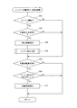
[エンジン自動停止・始動制御ルーチン]
図2に示すエンジン自動停止・始動制御ルーチンは、ECU30の電源オン中に所定周期で実行される。本ルーチンが起動されると、まず、ステップ101で、エンジン運転中であるか否かを判定し、次のステップ102で、自動停止要求が発生したか否かを判定する。ここで、自動停止要求は、例えば、ブレーキペダルが踏まれた状態で且つ車両が停止した状態が所定時間継続したときに発生する。
The processing contents of the routines for engine automatic stop / start control in FIGS. 2 and 3 executed by the ECU 30 will be described below.
[Engine automatic stop / start control routine]
The engine automatic stop / start control routine shown in FIG. 2 is executed at a predetermined cycle while the
上記ステップ101でエンジン運転中ではないと判定された場合、又は、上記ステップ102で自動停止要求が発生していないと判定された場合には、ステップ103、104の処理を飛び越してステップ105に進む。
If it is determined in
一方、上記ステップ101でエンジン運転中であると判定され、且つ、上記ステップ102で自動停止要求が発生したと判定された場合には、自動停止条件が成立したと判断して、ステップ103に進み、燃料噴射及び点火を停止させてエンジン11を自動的に停止させる停止制御を実行する。
On the other hand, if it is determined in
この後、ステップ104に進み、後述する図3のエンジン停止判定ルーチンを実行して、エンジン11の回転が停止したと判定したときにエンジン停止判定フラグENSTを「1」にセットする。
Thereafter, the routine proceeds to step 104, where an engine stop determination routine of FIG. 3 described later is executed, and when it is determined that the rotation of the
この後、ステップ105に進み、自動始動要求が発生したか否かを判定する。ここで、自動始動要求は、例えば、アクセルペダルが踏まれたとき、ブレーキペダルの踏み込みが解除されたとき、シフトレバーがPレンジからDレンジにシフトされたとき等に発生する。この後、ステップ106に進み、エンジン停止中であるか否かを、エンジン停止判定フラグENSTが「1」にセットされているか否かによって判定する。 Thereafter, the process proceeds to step 105, where it is determined whether or not an automatic start request has occurred. Here, the automatic start request is generated, for example, when the accelerator pedal is depressed, when the brake pedal is released, or when the shift lever is shifted from the P range to the D range. Thereafter, the routine proceeds to step 106, where it is determined whether or not the engine is stopped depending on whether or not the engine stop determination flag ENST is set to “1”.
上記ステップ105で自動始動要求が発生していないと判定された場合、又は、上記ステップ106でエンジン停止中ではない(ENST=0)と判定された場合には、ステップ107の処理を行うことなく、本ルーチンを終了する。
If it is determined in
一方、上記ステップ105で自動始動要求が発生したと判定され、且つ、上記ステップ106でエンジン停止中である(ENST=1)と判定された場合には、自動始動条件が成立したと判断して、ステップ107に進み、エンジン11を自動的に再始動させる始動制御を実行する。
On the other hand, if it is determined in
[エンジン停止判定ルーチン]
図3に示すエンジン停止判定ルーチンは、前記図2のエンジン自動停止・始動制御ルーチンのステップ104で実行されるサブルーチンである。本ルーチンが起動されると、まず、ステップ201で、各種の運転パラメータ(エンジン回転速度NE、クランク角CRNK、スロットル開度TA等)を読み込む。
[Engine stop determination routine]
The engine stop determination routine shown in FIG. 3 is a subroutine executed in
この後、ステップ202に進み、エンジン回転速度NEが所定回転速度K(例えば200rpm)よりも低くなったか否かによって、エンジン自動停止の際にエンジン回転速度NEが低下する過程で所定回転速度Kを通過したか否かを判定する。 Thereafter, the routine proceeds to step 202, where the predetermined rotational speed K is set in the process of decreasing the engine rotational speed NE when the engine is automatically stopped depending on whether the engine rotational speed NE is lower than a predetermined rotational speed K (for example, 200 rpm). It is determined whether or not it has passed.
このステップ202で、エンジン回転速度NEが所定回転速度K以上であると判定された場合には、まだエンジン回転速度NEが所定回転速度Kを通過していないと判断して、ステップ203に進み、マップ検索完了フラグFを「0」にリセット又は維持すると共に、エンジン回転速度NEが所定回転速度Kを通過した後の経過時間をカウントするためのカウンタCNTのカウント値を「0」にリセット又は維持する。このカウンタCNTは、所定時間毎にオートインクリメントされるカウンタである。
If it is determined in
その後、上記ステップ202で、エンジン回転速度NEが所定回転速度Kよりも低いと判定された場合には、エンジン回転速度NEが所定回転速度Kを通過したと判断して、ステップ204に進み、マップ検索完了フラグFが「0」であるか否かを判定する。
Thereafter, if it is determined in
エンジン回転速度NEが所定回転速度Kを通過した直後の1回目は、マップ検索完了フラグFが「0」であるため、このステップ204でマップ検索完了フラグFが「0」であると判定されて、ステップ205に進み、現在のクランク角CRNKを所定回転速度通過時のクランク角CRNK0 (エンジン回転速度NEが所定回転速度Kを通過したときのクランク角)とする。
Since the map search completion flag F is “0” for the first time immediately after the engine speed NE has passed the predetermined rotation speed K, it is determined in this
この後、ステップ206に進み、図4に示す停止判定時間DLYのマップを参照して、所定回転速度通過時のクランク角CRNK0 に応じた停止判定時間DLY(エンジン回転速度NEが所定回転速度Kを通過してからエンジン11の回転が停止するまでに要する時間)を算出する。このステップ206の処理が特許請求の範囲でいう停止判定時間算出手段としての役割を果たす。
Thereafter, the routine proceeds to step 206, and referring to the map of the stop determination time DLY shown in FIG. 4, the stop determination time DLY (the engine rotation speed NE is equal to the predetermined rotation speed K) corresponding to the crank angle CRNK0 when the predetermined rotation speed is passed. The time required for the rotation of the
図4に示す停止判定時間DLYのマップは、予め実験データや設計データ等に基づいて設定され、ECU30のROMに記憶されている。尚、図4は、4気筒エンジンの場合の停止判定時間DLYのマップの一例を示したものであり、4気筒エンジンでは180℃A毎に圧縮行程を迎えて180℃A周期で停止判定時間DLYが変化するため、0〜180℃Aの範囲の停止判定時間DLYのみを図示している。
The map of the stop determination time DLY shown in FIG. 4 is set in advance based on experimental data, design data, and the like, and is stored in the ROM of the
ところで、エンジン11が停止する際のスロットル開度TAによってポンピング損失や筒内圧が変化して、エンジン回転速度NEが所定回転速度Kを通過してからエンジン11の回転が停止するまでに要する時間が変化する。
By the way, the time required for the rotation of the
そこで、図4に示す停止判定時間DLYのマップは、スロットル開度TAの領域毎に設定され、例えば、スロットル開度TAが所定開度Aよりも小さい場合には、図4中に実線αで示すマップを選択して停止判定時間DLYを算出し、スロットル開度TAが所定開度A以上の場合には、図4中に点線βで示すマップを選択して停止判定時間DLYを算出することで、スロットル開度TAに応じて停止判定時間DLYを補正する。これにより、エンジン11が停止する際のスロットル開度TAに応じて、エンジン回転速度NEが所定回転速度Kを通過してからエンジン11の回転が停止するまでに要する時間が変化するのに対応して、停止判定時間DLYを適正に補正する。更に、冷却水温や油温等の温度情報に応じて停止判定時間DLYを補正するようにしても良い。
Therefore, the map of the stop determination time DLY shown in FIG. 4 is set for each area of the throttle opening TA. For example, when the throttle opening TA is smaller than the predetermined opening A, a solid line α in FIG. The map shown in FIG. 4 is selected to calculate the stop determination time DLY, and when the throttle opening degree TA is equal to or greater than the predetermined opening A, the map indicated by the dotted line β in FIG. 4 is selected to calculate the stop determination time DLY. Thus, the stop determination time DLY is corrected according to the throttle opening degree TA. As a result, the time required for the rotation of the
このようにして、停止判定時間DLYを設定した後、ステップ207に進み、カウンタCNTのカウント値を「0」にリセット又は維持すると共に、マップ検索完了フラグFを「1」にセットする。 After setting the stop determination time DLY in this way, the process proceeds to step 207 to reset or maintain the count value of the counter CNT to “0” and set the map search completion flag F to “1”.
このステップ207で、マップ検索完了フラグFを「1」にセットした後は、上記ステップ204で、マップ検索完了フラグFが「0」ではないと判定されて、上記ステップ205〜207の処理を飛び越してステップ208に進む。
After the map search completion flag F is set to “1” in
このステップ208では、カウンタCNTのカウント値(エンジン回転速度NEが所定回転速度Kを通過した後の経過時間)が停止判定時間DLY以上であるか否かによって、エンジン回転速度NEが所定回転速度Kを通過してから停止判定時間DLYが経過したか否かを判定する。
In
このステップ208で、カウンタCNTのカウント値が停止判定時間DLYに達していないと判定された場合には、エンジン回転速度NEが所定回転速度Kを通過してから停止判定時間DLYが経過していないと判断して、ステップ209に進み、まだエンジン11の回転が停止していないと判定して、エンジン停止判定フラグENSTを「0」に維持する。
If it is determined in
その後、上記ステップ208で、カウンタCNTのカウント値が停止判定時間DLY以上であると判定されたときに、エンジン回転速度NEが所定回転速度Kを通過してから停止判定時間DLYが経過したと判断して、ステップ210に進み、エンジン11の回転が停止したと判定して、エンジン停止判定フラグENSTを「1」にセットする。
Thereafter, when it is determined in
これらのステップ208〜210の処理が特許請求の範囲でいう停止判定手段としての役割を果たす。
The processing of these
以上説明した本実施例では、エンジン自動停止の際にエンジン回転速度NEが低下する過程で所定回転速度Kを通過するときのクランク角CRNK0 に基づいてエンジン11の回転が停止するまでに要する時間に相当する停止判定時間DLYを算出し、エンジン回転速度NEが所定回転速度Kを通過してから停止判定時間DLYが経過したときにエンジン11の回転が停止したと判定するようにしたので、エンジン11の回転が実際に停止するタイミングとほぼ同じタイミングでエンジン11の回転が停止したと判定することができ、エンジン11の停止を速やかに検出することができる。しかも、エンジン11の逆転を検出可能な特殊なセンサ等を新たに設ける必要がないため、低コスト化の要求も満たすことができる。
In the present embodiment described above, the time required for the rotation of the
また、エンジン11の停止を検出してからエンジン11の自動始動を開始するシステムでは、エンジン11の実際の停止タイミングに対して停止検出タイミングの遅れが大きいと、自動停止の際にエンジン11の回転が停止する前に自動始動要求が発生した場合に、自動始動要求が発生してから自動始動を開始するまでの遅れが大きくなってしまい、運転者に違和感(自動始動のもたつき感)を感じさせてしまうが、本実施例では、エンジン11の実際の停止タイミングに対する停止検出タイミングの遅れを小さくする(又はほぼ0とする)ことができるため、自動始動要求が発生してから自動始動を開始するまでの遅れを小さくすることができ、運転者に違和感(自動始動のもたつき感)を感じさせずに済む。
Further, in a system in which the automatic start of the
更に、本実施例では、スロットル開度TAに応じて停止判定時間DLYを補正するようにしたので、エンジン11が停止する際のスロットル開度TAに応じて、エンジン回転速度NEが所定回転速度Kを通過してからエンジン11の回転が停止するまでに要する時間が変化するのに対応して、停止判定時間DLYを適正に補正することができる。これにより、エンジン11が停止する際のスロットル開度に左右されずに停止判定時間DLYを精度良く設定することができ、エンジン11の停止判定精度を更に向上させることができる。
Furthermore, in this embodiment, the stop determination time DLY is corrected according to the throttle opening TA, so that the engine rotational speed NE is set to the predetermined rotational speed K according to the throttle opening TA when the
しかしながら、エンジン11が停止する際のスロットル開度が毎回ほぼ同じ開度になる場合やスロットル開度TAの影響が小さい場合には、図5に示す停止判定時間DLYのマップを参照して、所定回転速度通過時のクランク角CRNK0 に応じた停止判定時間DLYを算出することで、スロットル開度TAに応じた停止判定時間DLYの補正を省略するようにしても良い。
However, when the throttle opening when the
また、上記実施例では、エンジン11のみを動力源とする車両に本発明を適用したが、エンジンとモータを動力源とするハイブリッド車に本発明を適用しても良く、要は、自動停止条件が成立したときにエンジンを自動停止させ、自動始動条件が成立したときにエンジンを自動始動させるエンジン自動停止・始動装置を搭載した車両に広く適用して実施できる。
In the above embodiment, the present invention is applied to a vehicle using only the
11…エンジン(内燃機関)、12…吸気管、16…スロットルバルブ、17…スロットル開度センサ、21…燃料噴射弁、22…点火プラグ、23…排気管、28…クランク角センサ、30…ECU(停止判定時間算出手段,停止判定手段)
DESCRIPTION OF
Claims (2)
内燃機関の自動停止の際に内燃機関の回転速度が低下する過程で所定回転速度を通過するときのクランク角に基づいて内燃機関の回転が停止するまでに要する時間に相当する停止判定時間を算出する停止判定時間算出手段と、
内燃機関の自動停止の際に内燃機関の回転速度が前記所定回転速度を通過してから前記停止判定時間が経過したときに内燃機関の回転が停止したと判定する停止判定手段と
を備えていることを特徴とする内燃機関の制御装置。 In a control device for an internal combustion engine that automatically stops the internal combustion engine when a predetermined automatic stop condition is satisfied, and automatically starts the internal combustion engine when a predetermined automatic start condition is satisfied,
Calculates the stop determination time corresponding to the time required to stop the rotation of the internal combustion engine based on the crank angle when passing through the predetermined rotation speed while the rotation speed of the internal combustion engine decreases during the automatic stop of the internal combustion engine Stop determination time calculating means for
Stop determining means for determining that the rotation of the internal combustion engine has stopped when the stop determination time has elapsed after the rotational speed of the internal combustion engine has passed the predetermined rotational speed when the internal combustion engine is automatically stopped. A control device for an internal combustion engine.
Priority Applications (1)
| Application Number | Priority Date | Filing Date | Title |
|---|---|---|---|
| JP2007305241A JP2009127573A (en) | 2007-11-27 | 2007-11-27 | Control device for internal combustion engine |
Applications Claiming Priority (1)
| Application Number | Priority Date | Filing Date | Title |
|---|---|---|---|
| JP2007305241A JP2009127573A (en) | 2007-11-27 | 2007-11-27 | Control device for internal combustion engine |
Publications (1)
| Publication Number | Publication Date |
|---|---|
| JP2009127573A true JP2009127573A (en) | 2009-06-11 |
Family
ID=40818743
Family Applications (1)
| Application Number | Title | Priority Date | Filing Date |
|---|---|---|---|
| JP2007305241A Pending JP2009127573A (en) | 2007-11-27 | 2007-11-27 | Control device for internal combustion engine |
Country Status (1)
| Country | Link |
|---|---|
| JP (1) | JP2009127573A (en) |
Cited By (2)
| Publication number | Priority date | Publication date | Assignee | Title |
|---|---|---|---|---|
| JP2016136014A (en) * | 2015-01-23 | 2016-07-28 | トヨタ自動車株式会社 | Engine starter |
| JP2016173072A (en) * | 2015-03-17 | 2016-09-29 | トヨタ自動車株式会社 | Control device of multi-cylinder internal combustion engine |
-
2007
- 2007-11-27 JP JP2007305241A patent/JP2009127573A/en active Pending
Cited By (3)
| Publication number | Priority date | Publication date | Assignee | Title |
|---|---|---|---|---|
| JP2016136014A (en) * | 2015-01-23 | 2016-07-28 | トヨタ自動車株式会社 | Engine starter |
| JP2016173072A (en) * | 2015-03-17 | 2016-09-29 | トヨタ自動車株式会社 | Control device of multi-cylinder internal combustion engine |
| CN105986913A (en) * | 2015-03-17 | 2016-10-05 | 丰田自动车株式会社 | Control device of multi-cylinder internal combustion engine |
Similar Documents
| Publication | Publication Date | Title |
|---|---|---|
| JP2009024677A (en) | Control device for internal combustion engine | |
| JP2009115010A (en) | Control device of direct injection internal combustion engine | |
| JP2007262945A (en) | Abnormality diagnosis device for exhaust gas sensor | |
| JP2009036022A (en) | Dissimilar fuel mixing determination device of internal combustion engine | |
| US8798886B2 (en) | Vehicle engine controller | |
| JP2006029084A (en) | Control device of internal combustion engine | |
| JP3965577B2 (en) | Start control device for internal combustion engine | |
| JP2009036023A (en) | Different fuel mixing determination device of internal combustion engine | |
| JP4475207B2 (en) | Control device for internal combustion engine | |
| JP2008163774A (en) | Fuel property determining device for internal combustion engine | |
| JP6458453B2 (en) | Control device for internal combustion engine | |
| JP2008138579A (en) | Variable valve timing control device for internal combustion engine | |
| JP2009127573A (en) | Control device for internal combustion engine | |
| JP2006112385A (en) | Variable valve timing controller of internal combustion engine | |
| JP2010163916A (en) | Torque control device for internal combustion engine | |
| JP2010265877A (en) | Fuel injection control device for direct injection type internal combustion engine | |
| JP2005146908A (en) | Vibration dampening control device of internal combustion engine | |
| JP4491739B2 (en) | Control device for internal combustion engine | |
| JP2006037924A (en) | Control unit of vehicle | |
| JP5983553B2 (en) | Control device for internal combustion engine | |
| JP4697473B2 (en) | Control device for internal combustion engine | |
| JP2006029194A (en) | Controlling device for internal combustion engine | |
| JP2007138757A (en) | Start control device for internal combustion engine | |
| JP2007138881A (en) | Controller for internal combustion engine | |
| JP2007002685A (en) | Ignition timing control device for internal combustion engine |