JP2009127386A - Downpipe connecting structure - Google Patents

Downpipe connecting structure Download PDF

Info

Publication number
JP2009127386A
JP2009127386A JP2007306610A JP2007306610A JP2009127386A JP 2009127386 A JP2009127386 A JP 2009127386A JP 2007306610 A JP2007306610 A JP 2007306610A JP 2007306610 A JP2007306610 A JP 2007306610A JP 2009127386 A JP2009127386 A JP 2009127386A
Authority
JP
Japan
Prior art keywords
downpipe
joint
flange
inner joint
heel
Prior art date
Legal status (The legal status is an assumption and is not a legal conclusion. Google has not performed a legal analysis and makes no representation as to the accuracy of the status listed.)
Withdrawn
Application number
JP2007306610A
Other languages
Japanese (ja)
Inventor
Manabu Mizutani
学 水谷
Current Assignee (The listed assignees may be inaccurate. Google has not performed a legal analysis and makes no representation or warranty as to the accuracy of the list.)
Panasonic Electric Works Co Ltd
Original Assignee
Panasonic Electric Works Co Ltd
Priority date (The priority date is an assumption and is not a legal conclusion. Google has not performed a legal analysis and makes no representation as to the accuracy of the date listed.)
Filing date
Publication date
Application filed by Panasonic Electric Works Co Ltd filed Critical Panasonic Electric Works Co Ltd
Priority to JP2007306610A priority Critical patent/JP2009127386A/en
Publication of JP2009127386A publication Critical patent/JP2009127386A/en
Withdrawn legal-status Critical Current

Links

Images

Abstract

<P>PROBLEM TO BE SOLVED: To provide a downpipe connecting structure which can secure proper maintenance performance concurrently with the prevention of water leakage, while imparting a neat and good appearance to a downpipe arranged along a building wall. <P>SOLUTION: An upper portion of a tubular inner joint 3 is provided with an upper connecting portion 5 with an outside diameter almost equal in dimension to an inside diameter of the downpipe 1. The inner joint 3 is provided with a downpipe fixing protrusion 7 with an outside diameter almost equal in dimension to an outside diameter of the downpipe 1. The upper connecting portion 5 of the inner joint 3 is fitted into the lower end of the upside downpipe 1a from the inside in such a manner that a lower end surface of the upside downpipe 1a abuts on the top surface 7a of the downpipe fixing protrusion 7. Elastic packing 10 is provided over a circumferential direction on an inner peripheral surface of a downpipe supporting ring portion 9 of a downpipe supporting implement 4 which is attached to the building wall 2. At least a joint A1 between the upper connecting portion 5 and the lower end of the upside downpipe 1a is covered and sealed with the elastic packing 10 from the outside of the joint A1. <P>COPYRIGHT: (C)2009,JPO&INPIT

Description

本発明は、竪樋の接続構造に関するものである。   The present invention relates to a connecting structure for scissors.

竪樋1は建物壁2に取り付けた竪樋支持具4によって支持されて建物壁2に沿わせて配設される。一般に、竪樋支持具4は、建物壁2に取り付ける建物取付部8と、建物取付部8から外方に突設した竪樋支持環部9とを有しており、竪樋支持環部9を竪樋1にその外側から嵌合させることで、竪樋1を支持する。   The fence 1 is supported by the fence support 4 attached to the building wall 2 and arranged along the building wall 2. In general, the eaves support 4 includes a building attachment portion 8 attached to the building wall 2 and an eaves support ring portion 9 protruding outward from the building attachment portion 8. The heel 1 is supported by fitting it to the heel 1 from the outside.

また従来から、上下に隣接する竪樋1a,1b同士は、図4のように継手材20を用いて接続される(たとえば特許文献1参照)。図4の竪樋1の接続構造にあっては、接続した竪樋1間から水の漏れ出しを生じさせないように下側部材を上側部材の外側から被せるような構造が採用され、具体的には、継手材20の上部に設けた大径の上接続部5´を上側の竪樋1aの下端部にその外側から嵌合すると共に、継手材20の下部に設けた下接続部6を下側の竪樋1bの上端部にその内側から嵌合している。   Conventionally, the upper and lower adjacent flanges 1a and 1b are connected using a joint material 20 as shown in FIG. 4 (see, for example, Patent Document 1). In the connection structure of the collar 1 in FIG. 4, a structure is adopted in which the lower member is covered from the outside of the upper member so as not to cause leakage of water from between the connected collars 1. The upper connecting portion 5 ′ provided on the upper portion of the joint material 20 is fitted to the lower end portion of the upper flange 1 a from the outside, and the lower connecting portion 6 provided on the lower portion of the joint material 20 is It is fitted to the upper end of the side flange 1b from the inside.

この図4の竪樋1の接続構造によると、上側の竪樋1aに流れる排水を下側の竪樋1bで漏れなく受けるようにでき、接続した竪樋1間からの水の漏れ出しを生じないようにはできるが、上側の竪樋1aの下端部の外側を覆う継手材20の大径の上接続部5´が竪樋1の外径に凹凸を形成する凹凸形成部21となってしまい、同じく竪樋支持環部9による竪樋1の外径への凹凸も相俟って、竪樋1の外径への頻繁な凹凸によって、竪樋1にすっきりとした良好な外観を現出できない問題があった。   According to the connection structure of the ridge 1 in FIG. 4, the drainage flowing into the upper ridge 1a can be received without leakage by the lower ridge 1b, and water leaks between the connected ridges 1 The upper connecting portion 5 ′ of the joint material 20 that covers the outer side of the lower end portion of the upper flange 1 a becomes an unevenness forming portion 21 that forms unevenness on the outer diameter of the flange 1. In the same manner, the unevenness on the outer diameter of the heel 1 by the heel support ring portion 9 also brings about the appearance of a clean and good appearance on the heel 1 due to the frequent unevenness on the outer diameter of the heel 1. There was a problem that could not be issued.

ここで、竪樋1にすっきりとした良好な外観を現出させるべく、図5のような竪樋1の接続構造も提案されている(たとえば特許文献2参照)。つまり、この図5の竪樋1の接続構造では、先例の上接続部5´を採用せず、継手材20の上接続部5を上側の竪樋1aの下端部にその内側から嵌合する構造が採用されており、凹凸形成部21を形成させずに竪樋1にすっきりとした良好な外観を現出できるという利点はある。   Here, a connection structure of the heel 1 as shown in FIG. 5 has also been proposed in order to make the heel 1 have a clean and good appearance (see, for example, Patent Document 2). That is, in the connection structure of the heel 1 of FIG. 5, the upper connection portion 5 ′ of the previous example is not adopted, and the upper connection portion 5 of the joint material 20 is fitted to the lower end portion of the upper heel 1a from the inside thereof. Since the structure is adopted, there is an advantage that a clean and good appearance can be displayed on the ridge 1 without forming the unevenness forming portion 21.

しかしながら、この図5の竪樋1の接続構造では、先の図4の例のような上側の竪樋1aに流れる排水を下側の竪樋1bで漏れなく受け得る構造では無くなり、つまり、継手材20の上接続部5と上側の竪樋1aの下端部との継ぎ目A1から水の漏れ出しが発生する恐れが強い。そのため、上下に隣接する竪樋1間からの水の漏れ出しを生じさせないために、この例では継手材20の上接続部5と上側の竪樋1aの下端部との継ぎ目A1を接着剤22で隙間無く接着させている(なおこの例では、継手材20の下接続部6と下側の竪樋1bの上端部との継ぎ目A2も接着剤22で隙間無く接着させている)。このように継手材20と竪樋1を接着させると、竪樋1の一部が破損した等で一部の竪樋1を交換する必要が生じた際に、一部の竪樋1のみを取り外して交換することができなくなるものであり、メンテナンス性能に欠けるという問題があった。
特開平9−125636号公報 実開平6−14327号公報
However, in the connection structure of the ridge 1 in FIG. 5, the drainage that flows into the upper ridge 1a as in the example of FIG. 4 is not received without leakage in the lower ridge 1b. There is a strong possibility that water leaks from the joint A1 between the upper connection portion 5 of the material 20 and the lower end portion of the upper flange 1a. Therefore, in order to prevent the leakage of water from the upper and lower adjacent flanges 1, in this example, the joint A <b> 1 between the upper connection portion 5 of the joint material 20 and the lower end portion of the upper flange 1 a is used as the adhesive 22. (In this example, the joint A2 between the lower connecting portion 6 of the joint member 20 and the upper end portion of the lower flange 1b is also bonded without any gap with the adhesive 22). When the joint material 20 and the flange 1 are bonded in this way, when some of the flanges 1 need to be replaced because part of the flange 1 is damaged, only some of the flanges 1 are attached. There is a problem that it cannot be removed and replaced and lacks maintenance performance.
JP-A-9-125636 Japanese Utility Model Publication No. 6-14327

本発明は上記の点に鑑みてなされたものであり、その目的とするところは、建物壁に沿わせて配設する竪樋にすっきりとした良好な外観を現出するものでありながら、漏水も防止しつつ良好なメンテナンス性能を確保できる竪樋の接続構造を提供することを課題とするものである。   The present invention has been made in view of the above points, and the object of the present invention is to display a clean and good appearance on a wall disposed along a building wall, while leaking water. It is an object of the present invention to provide a spear connection structure that can ensure good maintenance performance while preventing the above.

上記課題を解決するために請求項1に係る発明にあっては、建物壁2に沿って配設される上下に隣接する竪樋1a,1b同士を接続する竪樋1の接続構造であって、筒状の内継手3の上部と下部に竪樋1の内径と略同じ外径を有する上接続部5と下接続部6を設けると共に上接続部5と下接続部6との間に竪樋1の外径と略同じ外径を有する竪樋止め凸部7を設け、上側の竪樋1aの下端面を竪樋止め凸部7の上面7aに当てるように内継手3の上接続部5を上側の竪樋1aの下端部に内側から嵌合すると共に、下側の竪樋1bの上端面を竪樋止め凸部7の下面7bに当てるように内継手3の下接続部6を下側の竪樋1bの上端部に内側から嵌合し、建物壁2に建物取付部8を取り付けた竪樋支持具4に該建物取付部8から突設した竪樋支持環部9を設けると共に、この竪樋支持環部9の内周面に周方向に亙って弾性パッキン10を設け、少なくとも上接続部5と上側の竪樋1aの下端部との継ぎ目A1にその外側から弾性パッキン10を被覆封止させて竪樋支持環部9で竪樋1を支持したことを特徴とする。   In order to solve the above-mentioned problem, the invention according to claim 1 is a connection structure of the fence 1 that connects the vertically adjacent fences 1 a and 1 b arranged along the building wall 2. The upper connecting portion 5 and the lower connecting portion 6 having an outer diameter substantially the same as the inner diameter of the flange 1 are provided on the upper and lower portions of the cylindrical inner joint 3, and the flange is interposed between the upper connecting portion 5 and the lower connecting portion 6. The upper connecting portion of the inner joint 3 is provided with a tacking convex portion 7 having an outer diameter substantially the same as the outer diameter of the collar 1 and the lower end surface of the upper collar 1a is brought into contact with the upper surface 7a of the tacking convex portion 7. 5 is fitted to the lower end portion of the upper flange 1a from the inside, and the lower connecting portion 6 of the inner joint 3 is fitted so that the upper end surface of the lower flange 1b is brought into contact with the lower surface 7b of the tacking convex portion 7. A heel support projecting from the building attachment portion 8 on the heel support 4 fitted to the upper end portion of the lower ridge 1b and attached to the building wall 2 with the building attachment portion 8 In addition to providing a portion 9, an elastic packing 10 is provided on the inner peripheral surface of the flange support ring portion 9 in the circumferential direction, and at least a joint A1 between the upper connection portion 5 and the lower end portion of the upper flange 1a. The elastic packing 10 is covered and sealed from the outside, and the heel 1 is supported by the heel support ring portion 9.

これによると、内継手3の上接続部5及び下接続部6を上側及び下側の各竪樋1a,1bの内側から嵌合させたので、内継手3が竪樋1の外側に重なる部位を形成することなく、また、上側及び下側の各竪樋1a,1bの間には内継手3の竪樋止め凸部7が外方へ露出するが竪樋止め凸部7と竪樋1とは略面一に連続するので、竪樋支持具4を介して竪樋1を建物壁2に沿わせて配設した外観にすっきりとした良好な外観を現出できる。ここで、内継手3が上側の竪樋1aの外側に重なる部位を形成しないため、そのままだと上接続部5と上側の竪樋1aの下端部との継ぎ目A1から漏水する恐れがある。しかしながら、上接続部5と上側の竪樋1aの下端部との継ぎ目A1は、上側の竪樋1aの内継手3への挿入止めとなる内継手3の竪樋止め凸部7の上面7aと上側の竪樋1aの下端面との間に形成される微小で安定形成される隙間で構成されるものであり、この内継手3の上接続部5と上側の竪樋1aの下端部との継ぎ目A1には、竪樋支持具4の竪樋支持環部9の内周面に周方向に亙って設けた弾性パッキン10が、その外側から被覆封止されたので、上接続部5と上側の竪樋1aの下端部との継ぎ目A1からの漏水の恐れを払拭できる。そして、この内継手3及び竪樋支持具4を用いた竪樋1a,1b同士の接続構造では竪樋1a,1b同士の接続に接着剤22を使用しないで済み、竪樋1の取り外しが可能になって良好なメンテナンス性能を確保できる。   According to this, since the upper connecting portion 5 and the lower connecting portion 6 of the inner joint 3 are fitted from the inside of the upper and lower flanges 1a and 1b, the portion where the inner joint 3 overlaps the outer side of the flange 1 In addition, the tacking projection 7 of the inner joint 3 is exposed to the outside between the upper and lower ribs 1a and 1b. Since it is substantially flush with the surface of the wall, it is possible to produce a clean and good appearance in an appearance in which the fence 1 is disposed along the building wall 2 via the fence support 4. Here, since the inner joint 3 does not form a portion overlapping the outside of the upper flange 1a, there is a possibility that water leaks from the joint A1 between the upper connecting portion 5 and the lower end portion of the upper flange 1a. However, the seam A1 between the upper connecting portion 5 and the lower end portion of the upper flange 1a is connected to the upper surface 7a of the barbed convex portion 7 of the inner joint 3 that is used to prevent the upper flange 1a from being inserted into the inner joint 3. It is composed of a small and stably formed gap formed between the lower end surface of the upper flange 1a, and the upper connection portion 5 of the inner joint 3 and the lower end portion of the upper flange 1a. Since the elastic packing 10 provided over the inner peripheral surface of the heel support ring portion 9 of the heel support 4 in the circumferential direction is covered and sealed from the outside at the seam A1, the upper connecting portion 5 and The fear of water leakage from the joint A1 with the lower end portion of the upper flange 1a can be wiped out. And, in the connection structure between the flanges 1a and 1b using the inner joint 3 and the flange support 4, it is not necessary to use the adhesive 22 to connect the flanges 1a and 1b. Therefore, good maintenance performance can be secured.

本発明にあっては、建物壁に沿わせて配設する竪樋にすっきりとした良好な外観を現出するものでありながら、漏水も防止しつつ良好なメンテナンス性能を確保できる、という利点を有する。   The present invention has the advantage that good maintenance performance can be ensured while preventing leakage even though it shows a clean and good appearance on the wall arranged along the building wall. Have.

以下、本発明を添付図面に示す実施形態に基いて説明する。   Hereinafter, the present invention will be described based on embodiments shown in the accompanying drawings.

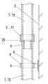
本例の竪樋1の接続構造は、図1のように、建物壁2に沿って配置される直管状の竪樋1を一直線状に連続させて接続する構造である。上下に隣接する竪樋1a,1b同士は内継手3や竪樋支持具4を用いて接続される。   As shown in FIG. 1, the connection structure of the eaves 1 in this example is a structure in which straight tubular eaves 1 arranged along the building wall 2 are connected in a straight line. The upper and lower adjacent flanges 1a and 1b are connected using the inner joint 3 and the flange support 4.

内継手3は、図2のように、筒形状に形成され、内継手3の上部には上側の竪樋1aの下端部にその内側から嵌合する上接続部5が設けられ、内継手3の下部には下側の竪樋1bの上端部の下端部にその内側から嵌合する下接続部6が設けられている。詳しくは、内継手3の上接続部5及び下接続部6は竪樋1の内径と略同径の外径寸法を有している。また、内継手3における上接続部5と下接続部6との間の上下中央部には、その外径が竪樋1の外径と略同じ寸法に形成された竪樋止め凸部7が設けられている。この竪樋止め凸部7は、上接続部5や下接続部6の外周面から外方へ突出する凸条部位であり、上接続部5に臨む上面7aと下接続部6に臨む下面7bとを有している。   The inner joint 3 is formed in a cylindrical shape as shown in FIG. 2, and an upper connection portion 5 that is fitted from the inside to the lower end portion of the upper flange 1 a is provided on the upper portion of the inner joint 3. A lower connecting portion 6 that is fitted from the inside to the lower end portion of the upper end portion of the lower flange 1b is provided at the lower portion of the lower heel. Specifically, the upper connection portion 5 and the lower connection portion 6 of the inner joint 3 have an outer diameter that is substantially the same as the inner diameter of the flange 1. In addition, at the upper and lower central portions between the upper connecting portion 5 and the lower connecting portion 6 in the inner joint 3, a tacking convex portion 7 having an outer diameter that is substantially the same as the outer diameter of the flange 1 is provided. Is provided. The tacking convex portion 7 is a convex portion projecting outward from the outer peripheral surface of the upper connecting portion 5 or the lower connecting portion 6, and an upper surface 7 a facing the upper connecting portion 5 and a lower surface 7 b facing the lower connecting portion 6. And have.

竪樋支持具4は、図3のように、建物壁2に沿わせて取り付ける建物取付部8と、建物取付部8から外方へ突設した環状の竪樋支持環部9とを有して形成される。竪樋支持環部9は、建物取付部8に連設された突出基端側の半弧部11aに対して突出先端側の半弧部11bが蝶番11cを介して回動自在に開閉する主体部11と、主体部の内周面に亙って沿設された弾性パッキン10とを有している。本例では主体部11は硬質樹脂で製造され、弾性パッキン10は軟質系エラストマーで製造されている。弾性パッキン10で構成される竪樋支持環部9の内径は竪樋1の外径よりも若干小さく形成されており、竪樋支持環部9に竪樋1を支持させた際には弾性パッキン10が竪樋1の外周面に沿って弾接するようにされている。   As shown in FIG. 3, the eaves support 4 includes a building attachment portion 8 attached along the building wall 2 and an annular eaves support ring portion 9 protruding outward from the building attachment portion 8. Formed. The eaves support ring portion 9 is a main body in which the projecting distal end side semi-arc portion 11b is pivotably opened and closed via a hinge 11c with respect to the projecting proximal end side semi-arc portion 11a provided continuously with the building mounting portion 8. It has the part 11 and the elastic packing 10 installed along the inner peripheral surface of the main-body part. In this example, the main body 11 is made of a hard resin, and the elastic packing 10 is made of a soft elastomer. The inner diameter of the eaves support ring portion 9 constituted by the elastic packing 10 is formed slightly smaller than the outer diameter of the eaves 1, and when the eaves support ring portion 9 supports the eaves 1, the elastic packing 10 is adapted to be elastically contacted along the outer peripheral surface of the rod 1.

上下に隣接する竪樋1a,1b同士を接続させるには、図1(b)のように、上側の竪樋1aの下端面を竪樋止め凸部7の上面7aに当てるように内継手3の上接続部5を上側の竪樋1aの下端部に内側から嵌合すると共に、下側の竪樋1bの上端面を竪樋止め凸部7の下面7bに当てるように内継手3の下接続部6を下側の竪樋1bの上端部に内側から嵌合する。上下に隣接する竪樋1a,1b同士の間で内継手3の竪樋止め凸部7が外方へ露出するものの、内継手3の竪樋止め凸部7はその外径が竪樋1の外径と略同じ寸法に形成されているので、上下に隣接する各竪樋1a,1bと内継手3の竪樋止め凸部7の各外周面が略面一に連続するようになり、凹凸の無い良好な外観が現出される。   In order to connect the vertically adjacent flanges 1a and 1b, as shown in FIG. 1 (b), the inner joint 3 is arranged so that the lower end surface of the upper flange 1a is brought into contact with the upper surface 7a of the tacking projection 7. The upper connecting portion 5 is fitted into the lower end portion of the upper flange 1a from the inside, and the lower end of the inner joint 3 is placed so that the upper end surface of the lower flange 1b is brought into contact with the lower surface 7b of the tacking convex portion 7. The connecting portion 6 is fitted to the upper end portion of the lower flange 1b from the inside. Although the barbed convex part 7 of the inner joint 3 is exposed to the outside between the upper and lower adjacent barbs 1a and 1b, the outer diameter of the barbed convex part 7 of the inner joint 3 is that of the bar 1 Since it is formed to have substantially the same dimension as the outer diameter, the outer peripheral surfaces of the flanges 1a and 1b adjacent to the upper and lower sides and the barbed convex portion 7 of the inner joint 3 are substantially flush with each other. Good appearance with no appearance appears.

そして、上記内継手3にて仮接続状態にある竪樋1は、該仮接続部位を建物壁2に固定した竪樋支持具4の竪樋支持環部9に支持させることで、建物壁2に沿わせて配設される。このとき竪樋支持環部9の弾性パッキン10が、少なくとも上接続部5と上側の竪樋1aの下端部との継ぎ目A1を被覆封止させる。なお本例では、弾性パッキン10は下接続部6と下側の竪樋1bの下端部との継ぎ目A2をも外側から被覆封止させている。   And the heel 1 in the temporarily connected state by the inner joint 3 is supported by the heel support ring portion 9 of the heel support 4 fixed to the building wall 2 so that the building wall 2 It is arranged along. At this time, the elastic packing 10 of the eaves support ring portion 9 covers and seals at least the joint A1 between the upper connection portion 5 and the lower end portion of the upper eaves 1a. In this example, the elastic packing 10 also covers and seals the joint A2 between the lower connection portion 6 and the lower end portion of the lower flange 1b from the outside.

このように竪樋1は、内継手3を用いると共に建物壁2に取り付ける竪樋支持具4を利用することで、上下に隣接する竪樋1a,1b同士を接続した状態で建物壁2に沿わせて配設される。このときには、内継手3の上接続部5及び下接続部6を上側及び下側の各竪樋1a,1bの内側から嵌合させたので、内継手3が竪樋1の外側に重なる部位(従来の凹凸形成部21)を形成することがない。また、上側及び下側の各竪樋1a,1bの間には内継手3の竪樋止め凸部7が外方へ露出するが竪樋止め凸部7と竪樋1とは略面一に連続するので、竪樋支持具4の竪樋支持環部9による取り付けの支障にならず、更に言うと、この竪樋止め凸部7は最終的には竪樋支持具4の竪樋支持環部9で被覆されて見えなくなるのであって、図1(a)のように建物壁2に沿って配設された竪樋1にはすっきりとした良好な外観が現出されるのである。   In this way, the heel 1 uses the inner joint 3 and the heel support 4 attached to the building wall 2 so that the heels 1a and 1b adjacent to each other in the vertical direction are connected to the building wall 2 in a state where they are connected to each other. Are arranged. At this time, since the upper connecting portion 5 and the lower connecting portion 6 of the inner joint 3 are fitted from the inside of the upper and lower flanges 1a and 1b, the portion where the inner joint 3 overlaps the outer side of the flange 1 ( The conventional unevenness forming part 21) is not formed. Further, between the upper and lower flanges 1a and 1b, the barbed convex portion 7 of the inner joint 3 is exposed outward, but the barbed convex portion 7 and the flange 1 are substantially flush with each other. Since it is continuous, it does not hinder the attachment of the heel support 4 by the heel support ring portion 9, and further speaking, this heel stop projection 7 is finally the heel support ring of the heel support 4. Since it is covered with the portion 9 and cannot be seen, a neat and good appearance appears on the eaves 1 arranged along the building wall 2 as shown in FIG.

ここで、内継手3が上側の竪樋1aの外側に重なる部位(従来の凹凸形成部21)を形成しない場合には、上接続部5と上側の竪樋1aの下端部との継ぎ目A1から上下に隣接する竪樋1間からの水の漏れ出しが発生する恐れが強い。しかしながら、本例では、上記のように上接続部5と上側の竪樋1aの下端部との継ぎ目A1は、竪樋支持具4の弾性パッキン10で被覆封止してあるため、該継ぎ目A1からの水の漏れ出しを防止することができたのである。   Here, in the case where the inner joint 3 does not form a portion overlapping the outside of the upper flange 1a (conventional unevenness forming portion 21), from the joint A1 between the upper connecting portion 5 and the lower end portion of the upper flange 1a. There is a strong risk of leakage of water from the upper and lower adjacent ridges 1. However, in this example, the seam A1 between the upper connecting portion 5 and the lower end portion of the upper flange 1a is covered and sealed with the elastic packing 10 of the rod support 4 as described above. It was possible to prevent water from leaking out.

そして、内継手3の上接続部5と上側の竪樋1aの下端部との継ぎ目A1からの水の漏れ出しを防止するのに、上記のように竪樋支持具4の弾性パッキン10の該継ぎ目A1への弾接による被覆にて行わせたので、従来の図5の例のように接着剤22による封止手段を用いずに済み、竪樋1の一部が破損した等で一部の竪樋1を交換する必要が生じた際に、一部の竪樋1のみを取り外して交換することが容易にできるものであり、良好なメンテナンス性能を確保できるという利点を有するのである。   And in order to prevent the leakage of water from the joint A1 between the upper connection portion 5 of the inner joint 3 and the lower end portion of the upper flange 1a, the elastic packing 10 of the flange support 4 as described above Since the cover A1 is covered by elastic contact with the seam A1, it is not necessary to use the sealing means by the adhesive 22 as in the conventional example of FIG. When it becomes necessary to replace the heel 1, only a part of the heel 1 can be easily removed and replaced, and this has the advantage that good maintenance performance can be ensured.

本発明の実施の形態の例の竪樋の接続構造であり、(a)は斜視図であり、(b)は縦断面図である。It is the connection structure of the bag of the example of embodiment of this invention, (a) is a perspective view, (b) is a longitudinal cross-sectional view. 同上の内継手の斜視図である。It is a perspective view of an inner joint same as the above. 同上の竪樋支持具であり、(a)は斜視図であり、(b)は平面図である。It is a heel support tool same as the above, (a) is a perspective view, (b) is a top view. 従来技術の例の竪樋の接続構造を示す縦断面図である。It is a longitudinal cross-sectional view which shows the connection structure of the collar of the example of a prior art. 従来技術の他例の竪樋の接続構造を示す縦断面図である。It is a longitudinal cross-sectional view which shows the connecting structure of the other example of a conventional technique.

符号の説明Explanation of symbols

1 竪樋
1a 上側の竪樋
1b 下側の竪樋
2 建物壁
3 内継手
4 竪樋支持具
5 上接続部
6 下接続部
7 竪樋止め凸部
7a 上面
7b 下面
8 建物取付部
9 竪樋支持環部
10 弾性パッキン
DESCRIPTION OF SYMBOLS 1 竪 樋 1a Upper ridge 1b Lower ridge 2 Building wall 3 Inner joint 4 下 Support 5 Upper connection portion 6 Lower connection portion 7 Securing convex portion 7a Upper surface 7b Lower surface 8 Building attachment portion 9 竪 樋Support ring 10 Elastic packing

Claims (1)

建物壁に沿って配設される上下に隣接する竪樋同士を接続する竪樋の接続構造であって、筒状の内継手の上部と下部に竪樋の内径と略同じ外径を有する上接続部と下接続部を設けると共に上接続部と下接続部との間に竪樋の外径と略同じ外径を有する竪樋止め凸部を設け、上側の竪樋の下端面を竪樋止め凸部の上面に当てるように内継手の上接続部を上側の竪樋の下端部に内側から嵌合すると共に、下側の竪樋の上端面を竪樋止め凸部の下面に当てるように内継手の下接続部を下側の竪樋の上端部に内側から嵌合し、建物壁に建物取付部を取り付けた竪樋支持具に該建物取付部から突設した竪樋支持環部を設けると共に、この竪樋支持環部の内周面に周方向に亙って弾性パッキンを設け、少なくとも上接続部と上側の竪樋の下端部との継ぎ目にその外側から弾性パッキンを被覆封止させて竪樋支持環部で竪樋を支持したことを特徴とする竪樋の接続構造。   A connecting structure for connecting the upper and lower adjacent flanges arranged along the building wall, wherein the upper and lower portions of the cylindrical inner joint have an outer diameter substantially the same as the inner diameter of the flange. Provided with a connecting part and a lower connecting part, a tacking convex part having an outer diameter substantially the same as the outer diameter of the collar is provided between the upper connecting part and the lower connecting part, and the lower end surface of the upper collar is Fit the upper joint of the inner joint to the lower end of the upper collar so that it touches the upper surface of the stopper protrusion, and apply the upper end of the lower flange to the lower surface of the stopper protrusion. A heel support ring projecting from the building mounting portion to a heel support with the lower joint portion of the inner joint fitted to the upper end of the lower heel from the inside and the building mounting portion attached to the building wall And an elastic packing is provided in the circumferential direction on the inner peripheral surface of the flange support ring portion, and at least a joint between the upper connection portion and the lower end portion of the upper flange Connecting structure Tatetoi characterized by supporting the vertical gutter in vertical gutter supporting ring portion elastic packing was sealed cover sealing from the outside.
JP2007306610A 2007-11-27 2007-11-27 Downpipe connecting structure Withdrawn JP2009127386A (en)

Priority Applications (1)

Application Number Priority Date Filing Date Title
JP2007306610A JP2009127386A (en) 2007-11-27 2007-11-27 Downpipe connecting structure

Applications Claiming Priority (1)

Application Number Priority Date Filing Date Title
JP2007306610A JP2009127386A (en) 2007-11-27 2007-11-27 Downpipe connecting structure

Publications (1)

Publication Number Publication Date
JP2009127386A true JP2009127386A (en) 2009-06-11

Family

ID=40818590

Family Applications (1)

Application Number Title Priority Date Filing Date
JP2007306610A Withdrawn JP2009127386A (en) 2007-11-27 2007-11-27 Downpipe connecting structure

Country Status (1)

Country Link
JP (1) JP2009127386A (en)

Cited By (1)

* Cited by examiner, † Cited by third party
Publication number Priority date Publication date Assignee Title
JP2012136901A (en) * 2010-12-27 2012-07-19 Sekisui Chem Co Ltd Down-pipe connection member

Cited By (1)

* Cited by examiner, † Cited by third party
Publication number Priority date Publication date Assignee Title
JP2012136901A (en) * 2010-12-27 2012-07-19 Sekisui Chem Co Ltd Down-pipe connection member

Similar Documents

Publication Publication Date Title
ES2772721T3 (en) Seal connector for pipes, such as for outlet pipes
JP2012233675A (en) Pipe unit for drain-up
KR20070013220A (en) Method of sealing for the blind branch outlet fitting system
JP2009127386A (en) Downpipe connecting structure
JP3155258U (en) Check valve and floor drain trap
US20080271391A1 (en) Vent Stack Repair Sleeve
CN102678924A (en) One-side hole waterproof seal assembly for connecting pipes in inserting mode
JP2006322515A (en) Pipe fitting
JP2008206705A (en) Water receiving structure for bathtub
JP4051578B1 (en) Opening closing method, closing aid and opening closing tool set
JP4036379B2 (en) Protective cover for water gate valve
JP6425322B1 (en) Water leakage prevention drain
JP4464617B2 (en) Connection structure of water supply / drainage pipe and pipe trap and S trap using the connection structure
JP5075767B2 (en) Connection structure between manhole and sewer main
JP2008240834A (en) Piping cover device
JP2006193987A (en) Drain-pipe cover
JP2011226154A (en) Drain pipe for being embedded in foundation and method of adjusting length of drain pipe for being embedded in foundation
JP4020069B2 (en) Cylindrical member connection structure and connection method
JP2007278352A (en) Ball joint dust cover
JP4589195B2 (en) Pipe connecting joint device and connection structure
JP4670628B2 (en) Eaves fittings
JP2555747Y2 (en) Drain masu mounting device
JP2007056448A (en) Water cut-off joint material
ATE409259T1 (en) CORNER CLADDING FOR THE JOINT AREA OF A WALL
JP3130730U (en) Drain pipe connection structure

Legal Events

Date Code Title Description
RD04 Notification of resignation of power of attorney

Free format text: JAPANESE INTERMEDIATE CODE: A7424

Effective date: 20100816

A300 Withdrawal of application because of no request for examination

Free format text: JAPANESE INTERMEDIATE CODE: A300

Effective date: 20110201