JP2009119589A - Robot simulator - Google Patents
Robot simulator Download PDFInfo
- Publication number
- JP2009119589A JP2009119589A JP2007299306A JP2007299306A JP2009119589A JP 2009119589 A JP2009119589 A JP 2009119589A JP 2007299306 A JP2007299306 A JP 2007299306A JP 2007299306 A JP2007299306 A JP 2007299306A JP 2009119589 A JP2009119589 A JP 2009119589A
- Authority
- JP
- Japan
- Prior art keywords
- robot
- teaching
- dimensional
- data
- tool
- Prior art date
- Legal status (The legal status is an assumption and is not a legal conclusion. Google has not performed a legal analysis and makes no representation as to the accuracy of the status listed.)
- Pending
Links
Images


Classifications
-
- Y—GENERAL TAGGING OF NEW TECHNOLOGICAL DEVELOPMENTS; GENERAL TAGGING OF CROSS-SECTIONAL TECHNOLOGIES SPANNING OVER SEVERAL SECTIONS OF THE IPC; TECHNICAL SUBJECTS COVERED BY FORMER USPC CROSS-REFERENCE ART COLLECTIONS [XRACs] AND DIGESTS
- Y02—TECHNOLOGIES OR APPLICATIONS FOR MITIGATION OR ADAPTATION AGAINST CLIMATE CHANGE
- Y02P—CLIMATE CHANGE MITIGATION TECHNOLOGIES IN THE PRODUCTION OR PROCESSING OF GOODS
- Y02P90/00—Enabling technologies with a potential contribution to greenhouse gas [GHG] emissions mitigation
- Y02P90/02—Total factory control, e.g. smart factories, flexible manufacturing systems [FMS] or integrated manufacturing systems [IMS]
Abstract
Description
本発明はロボットシミュレータに関し、特に産業用ロボットによる作業対象物(ワーク)を支持したり固定したりする治具の設計に適用されるシミュレータに関する。 The present invention relates to a robot simulator, and more particularly to a simulator applied to the design of a jig for supporting or fixing a work object (work) by an industrial robot.
自動車の製造ラインなどにおいては従来から産業用ロボットによる溶接作業が広く行われている。ロボットを用いて溶接を行う場合、アーク溶接であれば多関節ロボットの先端部に溶接トーチを取り付け、スポット溶接であれば多関節ロボットの先端部に溶接ガンを取り付け、ロボットの各関節を適当に動かすことにより溶接トーチ/溶接ガン(以下ツール)を被溶接物(ワーク)の近くまで移動させる。その後ワーク上の所定の溶接線や溶接点に従ってツールを移動させつつ溶接を行う。
こうした溶接を行う際にはワークを支持したり固定したりするために治具が用いられるのが一般的である。治具はワークの形状や溶接部位、ロボット先端に取り付けられたツールの形状や溶接時の姿勢などに応じて多くの種類が存在するが、溶接作業の邪魔にならないようロボット本体やツールと干渉しない形状に設計する必要がある。
そこで適切な形状の治具設計を簡易に行うことを目的として、自動車ボディにスポット溶接を施す作業において、溶接部位を3次元的に表す加工基準面データを3次元CAD・CAMシステムに入力し、さらにロボット先端に取り付けられる溶接ガンと溶接治具のデータとから溶接ガンと溶接治具とが干渉するか否かを判断し、干渉する場合には溶接治具の設計を変更するという方法があった(例えば特許文献1)。
また特許文献1のように離散的な位置ではなく、連続的に移動しながら溶接を行う場合において、溶接トーチの3次元形状データとユーザが指定した溶接部位の3次元形状から溶接作業中に溶接トーチが存在する領域(3次元軌跡)を算出し、溶接治具が溶接トーチの3次元軌跡と干渉するか否かをCADシステム上で確認し、干渉する場合には溶接治具の設計を修正する溶接治具設計装置があった(例えば特許文献2)。
When performing such welding, a jig is generally used to support or fix the workpiece. There are many types of jigs depending on the shape of the workpiece, the welding site, the shape of the tool attached to the robot tip, the posture during welding, etc., but it does not interfere with the robot body or tool so as not to interfere with the welding work. It is necessary to design the shape.
Therefore, for the purpose of easily designing a jig having an appropriate shape, in the work of spot welding to an automobile body, processing reference plane data representing a welded part in a three-dimensional manner is input to a three-dimensional CAD / CAM system, Further, it is possible to determine whether or not the welding gun and the welding jig interfere with each other based on the welding gun and welding jig data attached to the robot tip, and to change the design of the welding jig when there is an interference. (For example, Patent Document 1).
Further, when welding is performed while moving continuously instead of discrete positions as in
特許文献1や特許文献2に記載された発明では、溶接部位の位置や溶接部位の形状からツールの3次元位置や3次元軌跡を求め、それらが溶接治具と干渉するか否かによって溶接治具の設計の確認や変更を行っていた。すなわちワークに対して溶接作業を行う間の干渉の有無だけで溶接治具設計の良否を判断していた。
しかしながら実際のロボットによる溶接作業では、溶接の前後に溶接部位へのアプローチ、溶接完了後のワークからの離脱といった過程が必要である。また1つのワークに複数の溶接部位がある場合には、それらの間を移動する過程が必要である。
溶接ラインの生産性向上のためにはこうしたロボットの溶接部位へのアプローチ、溶接部位間の移動、ワークからの離脱に要する時間を短縮することが重要となる。特許文献1や特許文献2に記載の発明では、こうしたアプローチ、移動、離脱の際にロボットが最短経路を通過した際の干渉の有無まで確認できるものではなく、その意味では特許文献1や特許文献2によって設計された溶接治具も最適のものであるとは言えなかった。
In the inventions described in
However, in an actual robotic welding operation, a process of approaching the welded part before and after welding and detaching from the workpiece after completion of welding is necessary. Moreover, when there are a plurality of welding parts in one work, a process of moving between them is necessary.
In order to improve the productivity of the welding line, it is important to shorten the time required for the robot to approach the welding site, move between the welding sites, and leave the workpiece. In the inventions described in
また、特許文献1や特許文献2に記載の発明はあくまで治具の設計の検討や修正を行うものであって、ロボットのティーチングについての検討を行えるものではなかった。例えば溶接部位へのアプローチの際に治具との干渉が発生することが判明したが、治具の干渉部位の形状を変更すると多大なコストが発生するといった場合は、ティーチングデータに迂回点を設けてロボットの移動時間が伸長したとしても総合的な生産性の面からは結局得策であるということがありうる。
こうしたトレードオフの検討はティーチングデータと治具設計の双方を修正しながら行う必要があるが、特許文献1や特許文献2に記載の発明ではティーチングデータについては修正手段がなく総合的な検討を行うことができなかった。
本発明はこのような問題点に鑑みてなされたものであり、ロボットの作業部位へのアプローチやワークからの離脱の際のロボットやツールの軌跡をも考慮した治具の設計が行え、さらにはティーチングデータの修正も可能で、ロボットによる作業を総合的な視点から最適化することができるロボットシミュレータを提供することを目的とする。
In addition, the inventions described in
Such a trade-off study needs to be performed while correcting both teaching data and jig design. However, in the inventions described in
The present invention has been made in view of such problems, and it is possible to design a jig in consideration of the robot's approach to the work site and the trajectory of the robot or tool when leaving the workpiece. It is an object of the present invention to provide a robot simulator capable of correcting teaching data and optimizing work by a robot from a comprehensive viewpoint.
上記問題を解決するため、本発明は、次のように構成したのである。
請求項1に記載のロボットシミュレータは、オペレータからの入力を受け付ける入力装置と、前記入力装置からの入力に応じて多関節ロボットの動作をシミュレートする処理装置と、前記処理装置による処理結果を3次元グラフィックによって表示する表示装置とを備えるロボットシミュレータにおいて、前記処理装置は、前記多関節ロボットの動作を前記表示装置上においてティーチングするオフラインティーチング手段と、前記多関節ロボットの作業対象となるワークを支持または固定する治具を設計する3次元CAD手段とを備えたことを特徴とするものである。
請求項2に記載のロボットシミュレータは、前記オフラインティーチング手段は、前記多関節ロボットと前記多関節ロボットの先端に取り付けられたツールと前記ワークの3次元グラフィックを前記表示装置上に表示することを特徴とするものである。
請求項3に記載のロボットシミュレータは、前記オフラインティーチング手段は、前記オペレータによって作成されたティーチングデータから前記ツールの動作軌跡の3次元データを作成し、前記3次元CAD手段によって読み込み可能な形式で出力することを特徴とするものである。
請求項4に記載のロボットシミュレータは、前記3次元CAD手段は、前記ツールの動作軌跡の3次元データを読み込み、前記表示装置上に表示することを特徴とするものである。
請求項5に記載のロボットシミュレータは、前記3次元CAD手段は、前記表示装置上に表示された前記ツールの動作軌跡の3次元データのうち一部または全部について表示・非表示を切り替えることを特徴とするものである。
請求項6に記載のロボットシミュレータは、前記3次元CAD手段は、前記オペレータによって設計された前記治具の3次元CADデータを前記オフラインティーチング手段によって読み込み可能な形式で出力することを特徴とするものである。
In order to solve the above problem, the present invention is configured as follows.
The robot simulator according to
The robot simulator according to
The robot simulator according to
The robot simulator according to
The robot simulator according to
7. The robot simulator according to
本発明のロボットシミュレータによれば、オフラインティーチング手段によって作成したロボットの動作データから、そのロボット先端に取り付けられたツールの一連の動作軌跡を得ることができるので、溶接などの作業部分のみならず、アプローチや離脱の動作についても考慮した形状の治具設計が可能となり、ロボットの移動時間を短縮でき作業効率を向上させることができる。
また設計した治具のデータをオフラインティーチング手段に読み込ませ作業をシミュレートすることによって必要に応じてティーチングデータの方を修正し、ラインの総合的な生産性を向上することができる。
また治具設計の検討や修正を即座に行うことができ、設計に要する時間を短縮することができる。
According to the robot simulator of the present invention, it is possible to obtain a series of motion trajectories of the tool attached to the robot tip from the robot motion data created by the off-line teaching means. It is possible to design a jig that takes into account the approach and separation movements, shortening the movement time of the robot and improving work efficiency.
Moreover, the data of the designed jig can be read by the off-line teaching means and the work can be simulated to correct the teaching data as necessary, thereby improving the overall productivity of the line.
In addition, the jig design can be immediately examined and corrected, and the time required for the design can be shortened.
以下、本発明の実施の形態について図を参照して説明する。 Hereinafter, embodiments of the present invention will be described with reference to the drawings.
図1は、本発明のロボットシミュレータ1の全体構成を示すブロック図である。
図1において、2はマウスやキーボードといった入力装置、3は例えばCRTモニタや液晶モニタといった表示装置である。4は処理装置で、記憶装置5と、CPU6、メモリ7を備えている。記憶装置5は例えばハードディスクであって、オフラインティーチングプログラム8、3次元CADプログラム9を記憶している他、様々な種類のロボット、ツール、ワークの3次元形状データを記憶している。またロボットについては形状データに加え、実際のロボットと同様のリンクパラメータや各軸の動作可能範囲などの情報も記憶装置5に予め記憶されている。
本発明のロボットシミュレータはパーソナルコンピュータやワークステーションと同様の構成をもって提供される。記憶装置5に予め記憶されたオフラインティーチングプログラム8や3次元CADプログラム9は、入力装置2を介したユーザからの入力によって記憶装置5からメモリ7にロードされてCPU6によって実行される。オペレータは入力装置2によってオフラインティーチングプログラム8、3次元CADプログラム9に指示を行い、表示装置3にてその成果を確認しながら作業を進めることができる。
なお、図1は本発明のロボットシミュレータの主要な部分だけを描いたもので入力装置2や表示装置3と処理装置4との間のインターフェース部などについては省略している。
FIG. 1 is a block diagram showing the overall configuration of the
In FIG. 1, 2 is an input device such as a mouse or keyboard, and 3 is a display device such as a CRT monitor or a liquid crystal monitor. A
The robot simulator of the present invention is provided with the same configuration as a personal computer or workstation. The
FIG. 1 depicts only the main part of the robot simulator of the present invention, and the
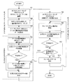
図2に本発明のロボットシミュレータの処理過程のフローチャートを示す。
まず、オペレータが入力装置2を使って記憶装置5からオフラインティーチングプログラム8を呼び出して起動させる。
オフラインティーチングプログラム8は記憶装置5からロボットやツール、ワークの3次元形状データを読み込んで表示装置3上に3次元モデルとして表示し、入力装置2を介して行われるオペレータからの指示に従って各モデルの配置やモデルに対する視点を自在に変更することができる。ただしツールの3次元モデルは実際のロボットと同様、ロボットの先端部に固定される。
FIG. 2 shows a flowchart of the process of the robot simulator of the present invention.
First, the operator calls and starts the
The off-
オフラインティーチングプログラム起動後、オペレータはまず治具設計の対象となる作業で使用されるロボット、ツール、ワークの3次元形状データを記憶装置5から読み込んで実際のラインと同様に配置し模擬的な作業環境を表示装置3上に構築する(図2のS1)。
図3にオフラインティーチングプログラム8によって構築した作業環境の例を示す。ツールとしてアーク溶接用のトーチ10をロボット先端に取り付け、ワーク11を溶接する作業の例である。
After starting the offline teaching program, the operator first reads the 3D shape data of the robot, tool, and workpiece used in the jig design work from the
FIG. 3 shows an example of a work environment constructed by the
3次元モデルの配置が完了すると、続いてオフラインティーチング作業を行う。実際のロボットを用いたティーチング作業では、ロボット制御装置に接続されたプログラミングペンダントを使ってロボットを動作させながら適当な教示点を記録していくが、オフラインティーチングではプログラミングペンダントの代わりに表示装置3上にプログラミングペンダント状の操作パネルを表示させ、入力装置2によって操作パネル上のボタンを押したり数値を入力したりする。
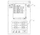
図4はオフラインティーチングプログラムによって表示装置3上に表示された操作パネルの例である。操作パネル上のJOG動作ボタン12や動作速度指定用のラジオボタン13をマウスでクリックすることで、実際のプログラミングペンダントと同様にロボットモデルの操作や動作速度の設定が行える。
オフラインティーチングプログラム8はキネマティクス演算処理機能を内蔵しており、前述のリンクパラメータやロボット各軸の動作可能範囲を参照して実際のロボットと同様の演算処理を行い、オペレータの入力に対して表示装置3上のロボットのモデルを動作させる。
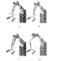
図5にオフラインティーチングプログラム8によるティーチングの具体例を示す。図5(a)〜(d)は図3と同じく先端にアーク溶接用のトーチ10を取り付けたロボットについて、ワーク11に対してアーク溶接を行う動作のティーチングの様子を示している。オペレータは操作パネルによりロボットモデルを操作してワーク11の溶接部位へのアプローチ、溶接作業、ワーク11からの離脱といった一連の動作をティーチングする(図2のS2)。具体的には、ロボットモデルを図5(a)〜(d)のように表示装置3上でJOG動作させティーチングしたい動作軌跡上の適当な位置まで誘導する。誘導後、操作パネルの「入力」ボタンを押せば、その時点のロボットの位置が教示点として記憶装置5に記録される。また同時にロボットの動作速度や、前の教示点から移動する際の補間方法も指定する。
補間方法とは、前の教示点から現在の教示点へと移動する際のロボット先端の動作軌跡を規定するもので、ロボット先端が教示点間を直線的に移動する直線補間や、3つ以上の教示点から構成される円弧に沿って移動する円弧補間の他、ロボットの各軸が各々次の教示点位置へと移動するリンク補間も選択可能である(リンク補間の場合はロボット先端の移動軌跡は不定となる)。
When the arrangement of the three-dimensional model is completed, an offline teaching operation is subsequently performed. In teaching work using an actual robot, an appropriate teaching point is recorded while operating the robot using a programming pendant connected to the robot controller, but in offline teaching, the
FIG. 4 is an example of the operation panel displayed on the
The
FIG. 5 shows a specific example of teaching by the
The interpolation method specifies the motion trajectory of the robot tip when moving from the previous teaching point to the current teaching point. Linear interpolation in which the robot tip moves linearly between teaching points, or three or more In addition to circular interpolation that moves along the circular arc composed of the teaching points, link interpolation in which each axis of the robot moves to the next teaching point position can be selected (in the case of link interpolation, movement of the robot tip) The trajectory is indefinite).
ティーチングの段階においては治具のモデルは表示装置3上に表示されておらず、オペレータは治具の形状を考慮する必要はなくロボットの動作時間が最短になるように溶接部位へのアプローチやワーク11からの離脱の軌跡をティーチングする。なお、図5ではワーク11に対する溶接作業のティーチングの部分を抜き出して示している。
一連のティーチング作業が完了すると、記憶装置5には溶接部位へのアプローチ、溶接作業、ワーク11からの離脱といった一連の動作軌跡を実現するティーチングデータが記録される。
At the teaching stage, the jig model is not displayed on the
When a series of teaching work is completed, the
オフラインティーチングプログラム8によるティーチング作業完了後、オペレータはオフラインティーチングプログラム8に対しツール(溶接トーチ10)の3次元モデルの動作軌跡データを出力させる(図2のS3)。
前述のようにオフラインティーチングプログラム8は予め準備されたツールの3次元形状データを記憶装置5から読み出すことができ、さらにティーチング作業によって決定した各教示点におけるロボットの先端位置と姿勢が分かるので、両者を組み合わせることによってワークモデルへのアプローチ、溶接作業、ワークからの離脱といった一連の動作に関する各教示点でのツール(溶接トーチ10)の3次元モデルの位置と姿勢のデータ、すなわち動作軌跡を得ることができる。
オフラインティーチングプログラム8によって出力されたツール(溶接トーチ)の3次元モデルの動作軌跡データは後述する3次元CADプログラム9で読み込むことができる形式になっており、記憶装置5に出力される。
After the teaching work by the
As described above, the off-
The operation trajectory data of the three-dimensional model of the tool (welding torch) output by the off-
続いて、オペレータは入力装置2を使って3次元CADプログラム9を呼び出して起動させる。3次元CADプログラム起動後、オペレータはツール(溶接トーチ10)の3次元モデルの動作軌跡データを記憶装置5から読み込む(図2のS4)。さらにワーク11の3次元モデルのデータも読み込む。図6に3次元CADプログラム9でツール(溶接トーチ10)の3次元モデルの動作軌跡14とワーク11を表示させた例を示す。
ここで、既にワーク11に対応する治具の3次元CADデータが存在している場合は、治具の3次元CADデータを読み込んでツール(溶接トーチ10)の3次元モデルの動作軌跡14との干渉が発生していないか確認する(図2のS5)。干渉する部分があれば、3次元CADプログラムによって治具の設計を変更する(図2のS6)。新規に治具を設計する場合であれば、図2のS5の過程は省略される。図7に3次元CADプログラム9を使って治具15を設計する様子を示す。
干渉しないように治具15の設計が完了したらオペレータは3次元CADプログラム9に治具15の3次元CADデータを出力させる(図2のS7)。
なお、図6、図7はツール(溶接トーチ10)の3次元モデルの動作軌跡データのうち、ワーク11に対する溶接作業の部分のみを表示した例である。ツール(溶接トーチ10)の3次元モデルの動作軌跡データを全て3次元CADプログラム9で表示すると治具の設計の邪魔になるような場合に、オペレータはツール(溶接トーチ10)の3次元モデルの動作軌跡データのうち任意の部分について表示、非表示を切り替えることができる。
Subsequently, the operator uses the
Here, when the 3D CAD data of the jig corresponding to the
When the design of the
6 and 7 are examples in which only the welding work portion for the
その後、オペレータは再度オフラインティーチングプログラム8を操作して治具15の3次元CADデータを読み込ませる(図2のS8)。
S1と同様にロボットやツール、ワークのモデルデータを呼び出し、ティーチング作業時と同様に配置して表示装置上に表示する。さらにS2でティーチングしたデータを呼び出してオフラインティーチングプログラム上で実行させる(図2のS9)。図8(a)〜(c)にその際の様子を示す。
ティーチングした一連の動作中にロボット本体およびツール(溶接トーチ10)と、治具15との間で干渉が発生しないかを確認する(図2のS10)。干渉が発生しないことが確認できれば、治具15の設計は完了する。
ロボットの動作軌跡と治具15との間で干渉が発生した場合は治具15の設計に誤りがあったことになり、再度3次元CADプログラム9にて治具設計を修正する必要がある。
ただし、干渉しないように治具の設計を修正すると治具の製造コストが上がったり所定の剛性を確保できなくなったりする場合もある。このような場合は、作業時間短縮と治具の設計変更に起因するコストや悪影響を比較検討し、ティーチングデータを修正する方が得策であると判断した場合には、ティーチングデータの方を修正する(図2のS11)。オフラインティーチングプログラム9ではティーチングデータ修正後、図2のS9に戻って即座に新しい動作軌跡と治具との干渉の確認を行うことができる。
干渉しないことが確認できれば、治具の設計が確定し、修正したティーチングデータを実際のロボットに適用することとする。
まだ干渉が発生する場合は再度治具設計の変更かティーチングデータの修正か適当な方を選択して干渉の確認を行う。
Thereafter, the operator operates the
The robot, tool, and workpiece model data are called up in the same manner as in S1, arranged in the same manner as in teaching work, and displayed on the display device. Further, the data taught in S2 is called and executed on the offline teaching program (S9 in FIG. 2). 8A to 8C show the situation at that time.
It is checked whether interference occurs between the robot body and the tool (welding torch 10) and the
If interference occurs between the robot movement locus and the
However, if the jig design is corrected so as not to interfere, the manufacturing cost of the jig may increase or a predetermined rigidity may not be ensured. In such cases, compare the cost and adverse effects caused by shortening the work time and changing the design of the jig, and if it is determined that it is better to correct the teaching data, correct the teaching data. (S11 in FIG. 2). In the
If it can be confirmed that there is no interference, the design of the jig is finalized, and the corrected teaching data is applied to the actual robot.
If interference still occurs, check the interference again by selecting the appropriate one of jig design change or teaching data correction.
以上ではアーク溶接用のトーチ10を例として説明したが、本発明のロボットシミュレータは同然ながら他の作業に適用可能である。図9ではスポット溶接用の溶接ガンをロボット先端に取り付けた場合において、3次元CADプログラム9にて溶接ガンの3次元モデルの動作軌跡16を表示させ、治具の設計を行っている様子を示している。
Although the
実施例1では、オフラインティーチングプログラム8と3次元CADプログラム9とが同一のパーソナルコンピュータやワークステーションで動作していたが、オフラインティーチングプログラム8と3次元CADプログラム9とが異なるパーソナルコンピュータやワークステーションで動作するように構成してもよい。
そうした場合、図10のようにオフラインティーチングプログラム8が出力したツールの動作軌跡の3次元モデルデータをフロッピーディスク(登録商標)やUSBメモリを介して3次元CADプログラム9が動作するパーソナルコンピュータやワークステーションへと送ればよい。また3次元CADプログラム9で設計した治具の3次元CADデータをオフラインティーチングプログラム8が動作するパーソナルコンピュータやワークステーションへと送って治具設計の検証を行うこともできる。
また両者がネットワークで接続されていれば、図11のようにフロッピーディスク(登録商標)やUSBメモリを介さずにツールの動作軌跡の3次元モデルデータや治具の3次元CADデータを互いにやりとりすることができる。
例えばティーチングを行う部門と治具設計を行う部門とが離れている場合でも即座にツールの動作軌跡の3次元モデルデータを送ることができる。
In the first embodiment, the
In such a case, as shown in FIG. 10, the personal computer or workstation in which the three-
If the two are connected via a network, the 3D model data of the tool movement trajectory and the 3D CAD data of the jig are exchanged without using a floppy disk (registered trademark) or USB memory as shown in FIG. be able to.
For example, even when the teaching department and the jig design department are separated, the 3D model data of the tool movement trajectory can be sent immediately.
1 ロボットシミュレータ
2 入力装置
3 表示装置
4 処理装置
5 記憶装置
6 CPU
7 メモリ
8 オフラインティーチングプログラム
9 3次元CADプログラム
10 溶接トーチ
11 ワーク
12 JOG動作ボタン
13 動作速度指定用のラジオボタン
14 溶接トーチの3次元モデルの動作軌跡
15 治具
16 溶接ガンの3次元モデルの動作軌跡
1
7
Claims (6)
前記処理装置は、前記多関節ロボットの動作を前記表示装置上においてティーチングするオフラインティーチング手段と、
前記多関節ロボットの作業対象となるワークを支持または固定する治具を設計する3次元CAD手段とを備えたことを特徴とするロボットシミュレータ。 An input device that receives an input from an operator, a processing device that simulates the operation of the articulated robot in response to an input from the input device, and a display device that displays a processing result by the processing device in a three-dimensional graphic. In the robot simulator,
The processing device includes offline teaching means for teaching the operation of the articulated robot on the display device;
A robot simulator comprising a three-dimensional CAD means for designing a jig for supporting or fixing a work to be a work target of the articulated robot.
Priority Applications (1)
| Application Number | Priority Date | Filing Date | Title |
|---|---|---|---|
| JP2007299306A JP2009119589A (en) | 2007-11-19 | 2007-11-19 | Robot simulator |
Applications Claiming Priority (1)
| Application Number | Priority Date | Filing Date | Title |
|---|---|---|---|
| JP2007299306A JP2009119589A (en) | 2007-11-19 | 2007-11-19 | Robot simulator |
Publications (2)
| Publication Number | Publication Date |
|---|---|
| JP2009119589A true JP2009119589A (en) | 2009-06-04 |
| JP2009119589A5 JP2009119589A5 (en) | 2011-06-30 |
Family
ID=40812321
Family Applications (1)
| Application Number | Title | Priority Date | Filing Date |
|---|---|---|---|
| JP2007299306A Pending JP2009119589A (en) | 2007-11-19 | 2007-11-19 | Robot simulator |
Country Status (1)
| Country | Link |
|---|---|
| JP (1) | JP2009119589A (en) |
Cited By (7)
| Publication number | Priority date | Publication date | Assignee | Title |
|---|---|---|---|---|
| CN105313120A (en) * | 2014-07-09 | 2016-02-10 | 发那科株式会社 | Robot program modification system |
| DE102018215057A1 (en) | 2017-09-12 | 2019-03-14 | Fanuc Corporation | MACHINE LEARNING DEVICE, ROBOTIC SYSTEM AND MACHINE LEARNING PROCEDURE |
| US10647003B2 (en) | 2017-05-18 | 2020-05-12 | Fanuc Corporation | Programming device and robot control method |
| WO2021200470A1 (en) * | 2020-03-30 | 2021-10-07 | ファナック株式会社 | Off-line simulation system |
| JP2021163395A (en) * | 2020-04-03 | 2021-10-11 | 川崎重工業株式会社 | Production line design method and production line design system |
| CN116100549A (en) * | 2023-01-30 | 2023-05-12 | 奇瑞新能源汽车股份有限公司 | Robot processing track design method, control device and medium |
| JP7383350B2 (en) | 2020-02-25 | 2023-11-20 | 株式会社ミツトヨ | Teaching program for image measurement equipment |
Citations (5)
| Publication number | Priority date | Publication date | Assignee | Title |
|---|---|---|---|---|
| JPS63273906A (en) * | 1987-05-06 | 1988-11-11 | Honda Motor Co Ltd | Production system for teaching data on industrial robot |
| JPH10264058A (en) * | 1997-03-21 | 1998-10-06 | Nissan Motor Co Ltd | Robot interference area setting program preparing method |
| JP2003127077A (en) * | 2001-10-19 | 2003-05-08 | Komatsu Ltd | Robot program modification device for working robot |
| JP2004280635A (en) * | 2003-03-18 | 2004-10-07 | Honda Motor Co Ltd | Simulation device, simulation method, and simulation program |
| WO2005124486A2 (en) * | 2004-06-15 | 2005-12-29 | Abb Ab | Method and system for off-line programming of multiple interacting robots |
-
2007
- 2007-11-19 JP JP2007299306A patent/JP2009119589A/en active Pending
Patent Citations (6)
| Publication number | Priority date | Publication date | Assignee | Title |
|---|---|---|---|---|
| JPS63273906A (en) * | 1987-05-06 | 1988-11-11 | Honda Motor Co Ltd | Production system for teaching data on industrial robot |
| JPH10264058A (en) * | 1997-03-21 | 1998-10-06 | Nissan Motor Co Ltd | Robot interference area setting program preparing method |
| JP2003127077A (en) * | 2001-10-19 | 2003-05-08 | Komatsu Ltd | Robot program modification device for working robot |
| JP2004280635A (en) * | 2003-03-18 | 2004-10-07 | Honda Motor Co Ltd | Simulation device, simulation method, and simulation program |
| WO2005124486A2 (en) * | 2004-06-15 | 2005-12-29 | Abb Ab | Method and system for off-line programming of multiple interacting robots |
| JP2008502488A (en) * | 2004-06-15 | 2008-01-31 | エービービー エービー | Method and system for offline programming of multiple interactive robots |
Cited By (13)
| Publication number | Priority date | Publication date | Assignee | Title |
|---|---|---|---|---|
| US9682475B2 (en) | 2014-07-09 | 2017-06-20 | Fanuc Corporation | Robot program modification system |
| CN105313120A (en) * | 2014-07-09 | 2016-02-10 | 发那科株式会社 | Robot program modification system |
| US11364636B2 (en) | 2017-05-18 | 2022-06-21 | Fanuc Corporation | Programming device and robot control method |
| US10647003B2 (en) | 2017-05-18 | 2020-05-12 | Fanuc Corporation | Programming device and robot control method |
| DE102018215057A1 (en) | 2017-09-12 | 2019-03-14 | Fanuc Corporation | MACHINE LEARNING DEVICE, ROBOTIC SYSTEM AND MACHINE LEARNING PROCEDURE |
| US10737385B2 (en) | 2017-09-12 | 2020-08-11 | Fanuc Corporation | Machine learning device, robot system, and machine learning method |
| DE102018215057B4 (en) * | 2017-09-12 | 2020-12-10 | Fanuc Corporation | Machine learning device, robot system and machine learning method |
| JP7383350B2 (en) | 2020-02-25 | 2023-11-20 | 株式会社ミツトヨ | Teaching program for image measurement equipment |
| WO2021200470A1 (en) * | 2020-03-30 | 2021-10-07 | ファナック株式会社 | Off-line simulation system |
| JP7381718B2 (en) | 2020-03-30 | 2023-11-15 | ファナック株式会社 | Offline simulation system |
| JP2021163395A (en) * | 2020-04-03 | 2021-10-11 | 川崎重工業株式会社 | Production line design method and production line design system |
| CN116100549A (en) * | 2023-01-30 | 2023-05-12 | 奇瑞新能源汽车股份有限公司 | Robot processing track design method, control device and medium |
| CN116100549B (en) * | 2023-01-30 | 2023-10-03 | 奇瑞新能源汽车股份有限公司 | Robot processing track design method, control device and medium |
Similar Documents
| Publication | Publication Date | Title |
|---|---|---|
| CN108453702B (en) | Robot simulator, robot system, and simulation method | |
| EP2993542B1 (en) | Teaching system, robot system, and teaching method | |
| JP6114361B1 (en) | Offline robot programming device | |
| JP6311421B2 (en) | Teaching system, robot system, and teaching method | |
| JP3819883B2 (en) | Robot program position correction device | |
| JP4917252B2 (en) | Arc welding equipment | |
| JP4621641B2 (en) | Robot teaching CAD apparatus and robot teaching method | |
| JP2009119589A (en) | Robot simulator | |
| US20170087717A1 (en) | Offline teaching device | |
| JP2003117863A (en) | Robot simulation device | |
| JP2007038366A (en) | Robot programming device | |
| JP2011048621A (en) | Robot off-line teaching method | |
| JP2005108144A (en) | Device for confirming correction data of robot | |
| JP2006190228A (en) | Operation program creating method | |
| JP2016074063A (en) | Robot teaching device for teaching robot on line | |
| US20230330852A1 (en) | Program generation device configured to generate operation program including operation symbol of robot apparatus | |
| JP2006350620A (en) | Method for action instruction of assembling mechanism in automatic assembling system | |
| JP2015098076A (en) | Robot program creation method, robot program creation device, program, and recording medium | |
| JP2009190113A (en) | Robot simulation device | |
| JP4574580B2 (en) | Offline teaching device for work robots | |
| JP2019209422A (en) | Method for producing teaching data for multi-joint robot | |
| JP2003127077A (en) | Robot program modification device for working robot | |
| JP2006085486A (en) | Nc working simulation method and nc working simulation device | |
| EP3263268B1 (en) | Offline teaching device | |
| JP2019089201A (en) | Teaching data creation device, method for controlling teaching data creation device, and robot system |
Legal Events
| Date | Code | Title | Description |
|---|---|---|---|
| A621 | Written request for application examination |
Free format text: JAPANESE INTERMEDIATE CODE: A621 Effective date: 20100119 |
|
| A521 | Written amendment |
Free format text: JAPANESE INTERMEDIATE CODE: A523 Effective date: 20110516 |
|
| A977 | Report on retrieval |
Free format text: JAPANESE INTERMEDIATE CODE: A971007 Effective date: 20110728 |
|
| A131 | Notification of reasons for refusal |
Free format text: JAPANESE INTERMEDIATE CODE: A131 Effective date: 20110808 |
|
| A521 | Written amendment |
Free format text: JAPANESE INTERMEDIATE CODE: A523 Effective date: 20111004 |
|
| A131 | Notification of reasons for refusal |
Free format text: JAPANESE INTERMEDIATE CODE: A131 Effective date: 20111124 |
|
| A02 | Decision of refusal |
Free format text: JAPANESE INTERMEDIATE CODE: A02 Effective date: 20120406 |