JP2009113916A - Carrier - Google Patents
Carrier Download PDFInfo
- Publication number
- JP2009113916A JP2009113916A JP2007288804A JP2007288804A JP2009113916A JP 2009113916 A JP2009113916 A JP 2009113916A JP 2007288804 A JP2007288804 A JP 2007288804A JP 2007288804 A JP2007288804 A JP 2007288804A JP 2009113916 A JP2009113916 A JP 2009113916A
- Authority
- JP
- Japan
- Prior art keywords
- fall prevention
- prevention member
- transported object
- fall
- state
- Prior art date
- Legal status (The legal status is an assumption and is not a legal conclusion. Google has not performed a legal analysis and makes no representation as to the accuracy of the status listed.)
- Pending
Links
Images


Abstract
Description
本発明は、建家の天井近傍など基準面の上方に敷設されるレールに沿って搬送物を吊り下げ状態で搬送する搬送車に関し、特に、搬送物の落下防止構造に関する。 The present invention relates to a transport vehicle that transports a transported object in a suspended state along a rail laid above a reference surface such as the vicinity of a ceiling of a building, and particularly relates to a fall prevention structure for the transported object.
半導体デバイスなどの製造工場においては、省スペース化や効率化などのため、床面に設置される半導体処理装置よりも上方の天井近傍の空間を用い、ウエハなどの搬送が行われている。 In manufacturing plants for semiconductor devices and the like, wafers and the like are transported using a space near the ceiling above the semiconductor processing apparatus installed on the floor in order to save space and improve efficiency.
この場合、天井近傍には、搬送軌道を形成するレールが張り巡らされており、当該レールに沿って走行する搬送車に吊り下げられた状態でウエハなどの搬送物は搬送される。 In this case, a rail that forms a transfer track is stretched around the ceiling, and a transfer object such as a wafer is transferred while being suspended from a transfer vehicle that runs along the rail.
以上のような吊り下げ型の搬送車には、走行中に搬送物が落下しないような落下防止策が施されている。 The suspension type transport vehicle as described above is provided with a fall prevention measure so that the transported object does not fall during traveling.
例えば、特許文献1に記載の搬送車は、搬送物を搬送中においては搬送物の下方に落下防止用の部材を配置し、搬送物を昇降させる際には前記部材を搬送物の昇降軌跡上から落下防止用の部材を退避させる機構を備えている。
ところが、搬送物を昇降させる際、何らかの不具合により前記落下防止用の部材が昇降軌跡上から退避することができず、搬送物と落下防止用の部材とが干渉する場合がある。この場合、落下防止用の部材から受ける力により搬送物が傷ついたり破損したりする場合があり、特に、搬送物が上昇している際に落下防止用の部材と搬送物とが干渉し干渉状態が持続すると、搬送物を上昇させようとする力と前記干渉により発生する力とが拮抗し、搬送物に大きな損傷を与え、最悪の場合搬送物が落下する懸念もある。 However, when raising or lowering the conveyed product, the drop preventing member cannot be retreated from the elevation locus due to some problem, and the conveyed product and the fall preventing member may interfere with each other. In this case, the transported object may be damaged or damaged by the force received from the fall prevention member, especially when the transported object is rising, the fall prevention member interferes with the transported object. If this is continued, the force to raise the conveyed product and the force generated by the interference will be antagonized, causing serious damage to the conveyed item, and in the worst case, the conveyed item may fall.
本発明は、上記問題に鑑みなされたものであり、前記落下防止用の部材が昇降軌道上から退避できない事態が発生した場合でも、落下防止用の部材から搬送物が受ける力をできる限り少なくして、搬送物の損傷を最小限とし、少なくとも搬送物を上昇させる力と搬送物が前記部材から受ける力とが拮抗するのを回避しうる搬送車の提供を目的としている。 The present invention has been made in view of the above-described problem, and even when a situation where the fall prevention member cannot be retracted from the lifting track occurs, the force received by the conveyed object from the fall prevention member is reduced as much as possible. Thus, it is an object of the present invention to provide a transport vehicle that minimizes damage to the transported object and can avoid at least the force that raises the transported object and the force that the transported object receives from the member.
上記目的を達成するために、本願発明に係る搬送車は、搬送物を吊り下げ状態で保持可能な保持装置と、基準面の上方に配置されるレールに支持されると共に、前記レールに沿って走行可能な台車と、前記台車に設けられ前記保持装置を基準面と前記レールとの間で昇降させる昇降装置とを備える搬送車であって、搬送物の基準面への落下を防止する落下防止部材と、落下する搬送物と干渉して搬送物を受け止める位置と、昇降する搬送物と干渉しない位置とに前記落下防止部材の位置を変換する変換装置と、上昇する搬送物が前記落下防止部材に接触した際に搬送物から受けた力で前記落下防止部材を退避方向に回動可能とし、落下する搬送物が前記落下防止部材に接触した際に搬送物から受ける力に抗して前記落下防止部材の退避方向とは逆の回動を停止可能とするように前記落下防止部材と前記変換装置とを接続するヒンジ構造部材とを備えることを特徴とする。 In order to achieve the above object, a transport vehicle according to the present invention is supported by a holding device capable of holding a transported object in a suspended state and a rail disposed above a reference plane, and along the rail. A carriage that includes a dolly capable of traveling and a lifting device that is provided on the carriage and raises and lowers the holding device between a reference plane and the rail, and prevents the fall of a conveyed product on the reference plane A member, a conversion device that converts the position of the fall prevention member into a position that receives the conveyance object by interfering with the falling conveyance object, and a position that does not interfere with the conveyance object that moves up and down, and the rising conveyance object is the fall prevention member The fall-preventing member can be rotated in the retracting direction by the force received from the transported object when it comes in contact with the transport object, and the fall is resisted against the force received from the transported object when the transporting object that falls The retraction direction of the prevention member and Characterized in that it comprises a reverse rotation to the fall preventing member so as to be stopped and a hinge structure member which connects the converter.
これにより、落下防止部材は、落下する搬送物を受け止めることができると共に、上昇する搬送物から与えられる力により、当該搬送物との強い干渉をかわす方向(前記力の方向)に回動する。従って、搬送物が上昇している際に、不本意に搬送物と落下防止部材とが干渉した場合でも、搬送物の損傷を最小限に留め、搬送物の落下を回避することが可能となる。また、搬送物と落下防止部材との干渉によって搬送車に発生する負荷を最小限に留めることも可能となる。 As a result, the fall prevention member can receive the fallen transported object and is rotated in a direction (a direction of the force) by which strong interference with the transported object is avoided by the force applied from the ascending transported object. Therefore, even when the transported object and the fall prevention member interfere with each other when the transported object is rising, it is possible to minimize the damage to the transported object and avoid the falling of the transported object. . It is also possible to minimize the load generated on the transport vehicle due to the interference between the transported object and the fall prevention member.
また、前記落下防止部材が落下する搬送物と干渉して搬送物を受け止める位置から昇降する搬送物と干渉しない位置までの間に存在する状態において、前記ヒンジ構造部材は、前記いずれの状態においても前記落下防止部材が鉛直方向下側から力を受けた場合、前記落下防止部材が退避方向に回動するように、前記落下防止部材と前記変換装置とを接続することが好ましい。 In addition, in the state where the fall prevention member exists between the position where the fall prevention member interferes with the fallen transported object and the position where the fall preventive member does not interfere with the lifted transported object, the hinge structure member is in any of the above states. When the fall prevention member receives a force from the lower side in the vertical direction, the fall prevention member and the conversion device are preferably connected such that the fall prevention member rotates in the retracting direction.
これにより、搬送物が揺れるなどして、搬送物が通常の昇降軌跡外で落下防止部材と干渉したとしても、落下防止部材は搬送物から受ける力により常に退避方向に回動することが可能となる。 This allows the fall prevention member to always rotate in the retraction direction due to the force received from the delivery object even if the delivery object sways and interferes with the fall prevention member outside the normal lifting locus. Become.
さらに、前記保持装置の上部から側方突出状に設けられる接触部材と、前記接触部材と前記落下防止部材との接触を検出し、検出状態を維持する検出装置とを備えることが好ましい。 Furthermore, it is preferable to include a contact member provided so as to protrude laterally from the upper part of the holding device, and a detection device that detects contact between the contact member and the fall prevention member and maintains the detection state.
これにより、搬送物と落下防止部材とが干渉する前に検出装置からの信号に基づき、例えばモータの電源を直接遮断するなど搬送物の上昇や下降を停止させる制御を行うことができ、搬送物の基準面への落下や、落下防止部材との干渉等による損傷の発生を抑制することに寄与することができる。 Thereby, based on the signal from the detection device before the conveyed object and the fall prevention member interfere, it is possible to perform control to stop the ascending or descending of the conveyed object, for example, by directly shutting off the power supply of the motor. It is possible to contribute to suppressing the occurrence of damage due to the fall on the reference plane or the interference with the fall prevention member.
さらに、前記検出装置は、前記接触部材が前記落下防止部材に対し下方から接触した場合の検出状態と、前記接触部材が前記落下防止部材に対し上方から接触した場合の検出状態とを区別して維持するものとすれば、上昇時と下降時でことなる制御を行うことが可能となる。 Further, the detection device maintains a distinction between a detection state when the contact member contacts the fall prevention member from below and a detection state when the contact member contacts the fall prevention member from above. If it does, it becomes possible to perform different control at the time of ascent and descent.
本願発明にかかる搬送車によれば、落下防止部材と搬送物が不本意に干渉した場合でも、落下防止部材による搬送物の損傷を可及的に抑制することが可能となる。 According to the transporting vehicle according to the present invention, even when the fall prevention member and the transported object unintentionally interfere with each other, it is possible to suppress damage to the transported object by the fall preventing member as much as possible.
次に、本発明の実施の形態に係る搬送車について、図面を参照しつつ説明する。
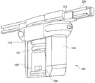
図1は、本実施の形態に係るカバーが施された搬送車を示す斜視図である。
Next, a transport vehicle according to an embodiment of the present invention will be described with reference to the drawings.
FIG. 1 is a perspective view showing a transport vehicle provided with a cover according to the present embodiment.
図2は、一部カバーをはずした搬送車を一部透過状態で示す正面図である。
これらの図に示すように、搬送車100は、搬送路を形成するレール200に対し垂下状に取り付けられ、レール200に沿って移動することができる車両であり、また、搬送物300を吊り下げ状に保持して搬送することができる車両である。搬送車100は、保持装置101と、台車102と、昇降装置103と、落下防止装置104とを備えている。
FIG. 2 is a front view showing the transport vehicle with a partial cover removed in a partially transparent state.
As shown in these drawings, the
台車102は、天井近傍に敷設されたレール200に係合状態で保持されると共に、レール200に沿って走行可能な台車である。台車102は、レール200の長さ方向に第一台車102aと第二台車102bとに分けられている(図2参照)。第一台車102aと第二台車102bとは、屈曲自在な継ぎ手121で連結されている。これは、台車102がカーブを通過する場合、第一台車102aと第二台車102bとが一直線上の配置から継ぎ手121部分を軸として折れ曲がった配置となることで、カーブに沿った走行を可能とするためである。なお、図1、図2は、一部カバーの施された状態の搬送車100が示されており、カバー内部の詳細な構造が示されていない部分がある。
The
昇降装置103は、基準面近傍からその上方に配置されるレール200近傍までの間で保持装置101を昇降させる装置であり、保持装置101が搬送物300を保持している場合は搬送物300も含めて昇降させることができる装置である。昇降装置103は、取付台131とウインチ部132とを備えている。
The
取付台131は、台車102にウインチ部132を取り付けるための部分であり、第一台車102aと第二台車102bとのそれぞれ対応した位置に、取付軸体133が上方突出状に設けられている。この取付軸体133は、台車102の二つの部分の底面にそれぞれ回動自在に係合している。これにより、台車102がカーブにさしかかり、第一台車102aと第二台車102bとが屈曲状に配置された状態となっても、昇降装置103は、自身の形状を変化させることなく台車102に吊り下げられた状態で、台車102の走行に追随することが可能となる。
The
ウインチ部132は、一直線上に並べられた二つの円筒形の巻き胴の組みが正三角形の各辺に対応する位置にそれぞれ配置され、巻き胴に巻き付けられたワイヤー134を巻き取ったり巻き戻したりして保持装置101を昇降させる装置である。従って、昇降装置103は6本のワイヤー134で保持装置101と接続されている。
The
ここで、基準面とは、特に限定された面を意味するものではなく、搬送車100から搬送物300が落下した場合の落下地点を含む面であり、搬送車100の位置により変化する面を意味している。例えば、搬送車100が床面の上方に位置していた場合は床面が基準面となり、搬送車100が何らかの装置の上方に位置していた場合は、当該装置の上面が基準面となる。また、搬送車100が屋外に位置していた場合は地面が基準面となる場合もある。
Here, the reference surface does not mean a particularly limited surface, and is a surface including a dropping point when the
保持装置101は、搬送物300を吊り下げ状態で保持可能な装置であり、また、基準面にある搬送物300に対し保持と開放とを自在に行うことができる機構を備えている。
The
また、保持装置101は、外観視円筒状のケーシング111を備えており、ケーシングの外周面には、接触センサ150が取り付けられている。なお、接触センサ150については後述する。
The
落下防止装置104は、搬送物300を搬送する際は、搬送物300の下方近傍を一部覆って搬送物300の落下を防止し、搬送物300を昇降させる際は、落下防止機能を解除することができる装置であり、落下防止部材141と、変換装置142と、ヒンジ構造部材143とを備えている。
The
変換装置142は、搬送物300が落下した場合に受け止めることができる位置(以下「閉状態」と記す場合がある。)と、通常の状態において昇降する搬送物300と干渉しない位置(以下「開状態」と記す場合がある。)とに落下防止部材141の位置を変換することができる装置である。変換装置142は、ヒンジ構造部材143を介して落下防止部材141が下端部に取り付けられており、落下防止部材141を開状態と閉状態とに変換するためのリンク機構が設けられている。
The
また、このリンク機構は、落下防止部材141等の自重により通常の状態において落下防止部材141が開状態となるものとなされ、さらに、開状態の落下防止部材141が振動などでばたつかないようにばねなどの付勢部材が備えられている。一方、変換装置142は、保持装置101が上限に配置された状態では落下防止部材141を閉状態とするために、保持装置101の上端と係合し、保持装置101と共に上昇する係合部材148を備えている。そして、リンク機構は、係合部材148が保持装置101と共に上昇する力を利用して落下防止部材141を閉状態とし、保持装置101が上限にある限りは閉状態を維持しうるものとなされている。
Further, in this link mechanism, the
図3は、落下防止部材とヒンジ構造部材とを示す斜視図である。
同図に示すように、落下防止部材141は、搬送物300の基準面への落下を防止する部材であり、長方形板状の部材である。また、落下防止部材141の長手方向両端部は、厚さ方向に折曲されている。これは、落下防止部材141の剛性、特にねじれ方向の剛性を高める為である。また、受け止めるべき搬送物300の方向に両端が折り曲げられているのは、落下防止部材141が搬送物300を受け止めた際、搬送物300が落下防止部材141の長さ方向にずり落ちることを防止するためである。なお、落下防止部材141の材質は特に限定されるものではないが、強度と軽量性との関係からアルミニウムやアルミニウムを基材とする合金を採用するのが好ましい。また、リブなどを設けることで、強度と軽量性との向上を図ってもよい。
FIG. 3 is a perspective view showing the fall prevention member and the hinge structure member.
As shown in the figure, the
ヒンジ構造部材143は、上昇する搬送物300が落下防止部材141に接触した際に搬送物300から受けた力(例えば鉛直下方からの力)で落下防止部材141を退避方向(同図中矢印方向)に回動可能とし、落下する搬送物300が落下防止部材141に接触した際に搬送物300から受ける力に抗して落下防止部材141の退避方向とは逆の方向の回動を停止可能とするように落下防止部材141と変換装置142とを接続する部材である。ヒンジ構造部材143は、基板144と、回動部材145と、停止板146とを備えている。
The
基板144は、変換装置142に固定的に取り付けられる長方形板状の板材であり、落下防止部材141と同じ材質からなっている。基板144には、変換装置に取り付けるためのねじ孔が四つ設けられている。
The
回動部材145は、基板144と落下防止部材141とを回動自在に接続する部材であり、円筒状の筒体を端部に備える矩形の第一板と第二板と軸体とで構成されるいわゆる蝶番である。回動部材145は、基板144の幅方向端部に第一板が取り付けられ、落下防止部材141の幅方向端部に第二板が取付られ、第一板の筒体と第二板の筒体とが同一の軸体で結合されることで、落下防止部材141と基板144とを接続している。
The
停止板146は、回動部材145による基板144に対する落下防止部材141の回動を所定の位置で停止させるための部材であり、基板144の幅方向端部裏面と落下防止部材141の幅方向端部裏面とを跨ぐように配置され、落下防止部材141側に取り付けられている。
The
図4は落下防止部材とヒンジ構造部材との取付部分を示す側面図である。同図は、落下防止部材を切断した状態で示している。 FIG. 4 is a side view showing an attachment portion between the fall prevention member and the hinge structure member. This figure shows the fall prevention member in a cut state.
同図に示すように、ヒンジ構造部材143はさらに、退避方向と逆の方向(図中矢印方向)に付勢するねじりばね147を備えている。このねじりばね147は、搬送車100が通常の搬送状態にある時に、振動などで落下防止部材141がばたつくのを抑止し、また、変換装置142により、落下防止部材141が開状態や閉状態に変換される際にばたつかず、基板144と面一状態を維持するためである。また、ねじりばね147の付勢力は、上記ばたつきを抑止し、面一状態を維持できる強さであり、ねじりばね147の付勢力に抗して搬送物300が落下防止部材141に衝突した際に、搬送物300に対し損傷を与えない程度の弱さである。
As shown in the figure, the
また、同図(a)に示すように、停止板146は、基板144と落下防止部材141とが面一となった状態で、基板144の背面(回動部材145が取り付けられている面と反対側の面)と当接しているため、図中の矢印の方向にはこれ以上落下防止部材141が回動することはない。
Further, as shown in FIG. 5A, the
なお、同図に示すように基板144の端面と落下防止部材141の端面とが突き合わせ状態になっているため、この部分によっても図中の矢印の方向にはこれ以上落下防止部材141が回動することはないが、落下防止部材141は落下する搬送物300を受け止める必要があるため、停止板146により強度を向上させている。
Since the end face of the
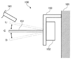
図5は、接触センサを示す側面図である。
同図に示すように、接触センサ150は、接触部材151と、検出装置152とを備えている。また、接触センサ150は、取付具153により保持装置101の外周面に取り付けられている。
FIG. 5 is a side view showing the contact sensor.
As shown in the figure, the
接触部材151は、保持装置101の上部から側方突出状に設けられる棒状の部材であり、直径線上両端に設けられ、かつ、落下防止装置104に向かって延びた状態となるように配置されている。
The
検出装置152は、接触部材151の基端部と接続されており、接触部材151が中立の状態(図中C)と、接触部材151が上向きに倒れている状態(図中U)と、接触部材151が下向きに倒れている状態(図中D)との3状態を区別して検出することができる装置である。なお、中立状態と倒れている状態(上向き下向きを問わず)の2状態を検出するものでもかまわない。
The
接触センサ150は、何らかの外力(例えば落下防止部材141との接触による外力)が接触部材151にくわえられ、ある状態から異なる状態に変化した場合、その状態が維持されるものとなっている。例えば、接触部材151が中立状態Cにある場合、外力により接触部材151が上向きに倒れた状態Uになれば、当該状態が維持され、当該状態である旨の信号を出力し続けることが可能となっている。具体的には、トグルスイッチを接触センサ150として用いることが可能である。この場合、信号を出力し続けるとは、接点同士が切れた状態、または、接点同士が導通した状態を維持し続けることである。
The
また、接触センサ150の情報を取得するための信号線は、保持装置101の揺れを検知するセンサの信号線とシリーズで接続されており、保持装置101の揺れか、接触センサ150の接触かのいずれかを検出すれば、搬送車100は停止するものとなっている。さらに、前記信号線には、保持装置101を昇降させる複数あるワイヤー134の一部が用いられている。
In addition, the signal line for acquiring information of the
次に、本願発明に係る搬送車100の動作態様を説明する。
図6は、搬送物を昇降させる通常の動作態様を示す図である。
Next, the operation | movement aspect of the
FIG. 6 is a diagram illustrating a normal operation mode for raising and lowering a conveyed product.
同図(a)に示すように、搬送物300を搬送する搬送状態では、変換装置142は、搬送物300が落下した場合でも、搬送物300を受け止める位置に落下防止部材141を配置している。つまり、保持装置101に保持されている搬送物300の下方近傍に二つの落下防止部材141が内方に向くように水平に配置されている。従って、もし保持装置101が搬送物300を保持している状態が解除され、搬送物300が落下を始めても、すぐに落下防止部材141が搬送物300を受け止めるため、搬送物300に多大な衝撃を与えることなく、また、搬送車100の下方にある基準面や基準面に載置されているような物品を損傷させることがない。
As shown in FIG. 5A, in the transport state in which the transported
また、同図(b)に示すように、搬送物300を昇降させる際には、保持装置101が上限から降下するにつれて係合部材148も所定の位置まで降下するため、落下防止部材141等の自重をキャンセルする力が消失し、変換装置142は、落下防止部材141の位置を開状態に変換する。以上により通常の昇降作業においては搬送物300と落下防止部材141とが干渉することはない。
Further, as shown in FIG. 5B, when the transported
次に、本願発明に係る搬送車100が異常に動作した場合の態様を説明する。
図7は、搬送物を昇降させる異常な場合の動作態様を示す図である。
Next, an aspect when the
FIG. 7 is a diagram illustrating an operation mode in an abnormal case where the conveyed product is raised and lowered.
同図(a)に示すように、図中左側の変換装置142が異常を来し、落下防止部材141が完全な開状態になっていないにもかかわらず、保持装置101が上昇してきた場合、まず、保持装置101の上部に取り付けられた接触センサ150が落下防止部材141と接触する。搬送車100は、接触センサ150の検出結果に基づき、即座に昇降装置103に保持装置101が上昇するのを停止させる制御を行う。しかしながら、制御のタイムラグなどにより、接触センサ150が接触を検出してからもしばらくは保持装置101が上昇し続ける。
As shown in FIG. 6A, when the
従って、同図(b)に示すように、搬送物300と落下防止部材141とが干渉し、接触することとなる。しかし、落下防止部材141は、搬送物300と接触する際に発生する力によって、ヒンジ構造部材143に対し落下防止部材141が退避方向(図中矢印方向)に回動する。このため、搬送物300は、落下防止部材141から強い力を受けることがないため、損傷や破損などが発生し難く、また、落下防止部材141からの力により保持装置101による保持が解除されて、搬送物300が落下してしまう事態を回避することが可能となる。
Therefore, as shown in FIG. 5B, the conveyed
以上のような構成とすることで、通常の状態であれば、搬送物の基準面への落下を防止することができる一方、変換装置142の不具合など異常な状態の場合は、落下防止部材141に緊急回避的な動作をさせることが可能となる。またこの緊急回避的な動作は、非常に簡単な機械的構造で実現され、変換装置142等に比べても遙かに簡単な構造であるため、不具合の発生がきわめて少なく高い信頼性を獲得することが可能である。
With the above-described configuration, the transported object can be prevented from dropping onto the reference surface in a normal state. On the other hand, in an abnormal state such as a malfunction of the
なお、上記実施の形態では、接触センサ150が取り付けられた搬送車100について説明したが、本願発明は、これに限定されるものではない。例えば、接触センサ150を設けなくても、上昇中の搬送物300に不本意に落下防止部材141が干渉した場合、落下防止部材141が退避方向に回動して、搬送物300が損傷するのを回避することができる点は、上記説明と同様である。
In addition, in the said embodiment, although the
またこれは、接触センサ150が故障のため、落下防止部材141との接触が検出できなかった場合も、同様の作用効果を享受することが可能である。
Further, even when the
本発明は、天井走行車など搬送物を高所に持ち上げた上で搬送する搬送車に適用しうる。 The present invention can be applied to a transport vehicle that transports a transported object such as an overhead traveling vehicle after lifting it to a high place.
100 搬送車
101 保持装置
102 台車
102a 第一台車
102b 第二台車
103 昇降装置
104 落下防止装置
111 ケーシング
121 継ぎ手
131 取付台
132 ウインチ部
133 取付軸体
134 ワイヤー
141 落下防止部材
142 変換装置
143 ヒンジ構造部材
144 基板
145 回動部材
146 停止板
147 ねじりばね
148 係合部材
150 接触センサ
151 接触部材
152 検出装置
153 取付具
200 レール
300 搬送物
DESCRIPTION OF
Claims (4)
搬送物の基準面への落下を防止する落下防止部材と、
落下する搬送物と干渉して搬送物を受け止める位置と、昇降する搬送物と干渉しない位置とに前記落下防止部材の位置を変換する変換装置と、
上昇する搬送物が前記落下防止部材に接触した際に搬送物から受けた力で前記落下防止部材を退避方向に回動可能とし、落下する搬送物が前記落下防止部材に接触した際に搬送物から受ける力に抗して前記落下防止部材の退避方向とは逆の回動を停止可能とするように前記落下防止部材と前記変換装置とを接続するヒンジ構造部材と
を備える搬送車。 A holding device that can hold a conveyed product in a suspended state, a carriage that is supported by a rail disposed above the reference plane and that can travel along the rail, and the holding device that is provided on the carriage as a reference A transport vehicle comprising a lifting device that lifts and lowers between a surface and the rail,
A fall-preventing member that prevents the transported object from dropping onto the reference surface;
A conversion device that converts the position of the fall prevention member into a position that receives a conveyed object by interfering with a falling conveyed object, and a position that does not interfere with a conveyed object that moves up and down;
The fall preventive member can be rotated in the retracting direction by the force received from the transported object when the rising transported object contacts the fall preventing member, and the transported object when the falling transported object contacts the fall preventing member. A conveyance vehicle comprising a hinge structure member that connects the fall prevention member and the conversion device so that rotation opposite to the retracting direction of the fall prevention member can be stopped against a force received from the fall.
前記ヒンジ構造部材は、
前記いずれの状態においても前記落下防止部材が鉛直方向下側から力を受けた場合、前記落下防止部材が退避方向に回動するように、前記落下防止部材と前記変換装置とを接続する請求項1に記載の搬送車。 In a state where the fall prevention member exists between the position where the fall prevention member interferes with the fallen transported object and receives the transported object and the position where it does not interfere with the lifted transported object,
The hinge structure member is
The fall prevention member and the conversion device are connected so that the fall prevention member rotates in the retracting direction when the fall prevention member receives a force from the lower side in the vertical direction in any state. 1. The transport vehicle according to 1.
前記接触部材と前記落下防止部材との接触を検出し、検出状態を維持する検出装置と
を備える請求項1に記載の搬送車。 A contact member provided so as to project laterally from the upper part of the holding device;
The transport vehicle according to claim 1, further comprising: a detection device that detects contact between the contact member and the fall prevention member and maintains the detection state.
Priority Applications (1)
| Application Number | Priority Date | Filing Date | Title |
|---|---|---|---|
| JP2007288804A JP2009113916A (en) | 2007-11-06 | 2007-11-06 | Carrier |
Applications Claiming Priority (1)
| Application Number | Priority Date | Filing Date | Title |
|---|---|---|---|
| JP2007288804A JP2009113916A (en) | 2007-11-06 | 2007-11-06 | Carrier |
Publications (1)
| Publication Number | Publication Date |
|---|---|
| JP2009113916A true JP2009113916A (en) | 2009-05-28 |
Family
ID=40781507
Family Applications (1)
| Application Number | Title | Priority Date | Filing Date |
|---|---|---|---|
| JP2007288804A Pending JP2009113916A (en) | 2007-11-06 | 2007-11-06 | Carrier |
Country Status (1)
| Country | Link |
|---|---|
| JP (1) | JP2009113916A (en) |
Cited By (7)
| Publication number | Priority date | Publication date | Assignee | Title |
|---|---|---|---|---|
| JP2011016628A (en) * | 2009-07-09 | 2011-01-27 | Unit Safety Sign Co Ltd | Suspending cargo alarm device and suspending-moving method of suspending cargo |
| CN102897647A (en) * | 2012-10-12 | 2013-01-30 | 天津重型装备工程研究有限公司 | Crank block type automatic lifting appliance |
| JP2015064304A (en) * | 2013-09-25 | 2015-04-09 | 株式会社東芝 | Radioactive waste storage container handling device |
| JP2016072050A (en) * | 2014-09-30 | 2016-05-09 | 日産自動車株式会社 | Assembly device and assembly method of battery pack |
| CN111620063A (en) * | 2019-02-27 | 2020-09-04 | 村田机械株式会社 | Conveying vehicle |
| CN113845038A (en) * | 2021-09-27 | 2021-12-28 | 中集车辆(集团)股份有限公司 | Plate material conveying device and plate material conveying method |
| CN115432597A (en) * | 2022-11-08 | 2022-12-06 | 烟台融汇工程管理服务有限公司 | Template handling machine for water conservancy construction |
-
2007
- 2007-11-06 JP JP2007288804A patent/JP2009113916A/en active Pending
Cited By (8)
| Publication number | Priority date | Publication date | Assignee | Title |
|---|---|---|---|---|
| JP2011016628A (en) * | 2009-07-09 | 2011-01-27 | Unit Safety Sign Co Ltd | Suspending cargo alarm device and suspending-moving method of suspending cargo |
| CN102897647A (en) * | 2012-10-12 | 2013-01-30 | 天津重型装备工程研究有限公司 | Crank block type automatic lifting appliance |
| JP2015064304A (en) * | 2013-09-25 | 2015-04-09 | 株式会社東芝 | Radioactive waste storage container handling device |
| JP2016072050A (en) * | 2014-09-30 | 2016-05-09 | 日産自動車株式会社 | Assembly device and assembly method of battery pack |
| CN111620063A (en) * | 2019-02-27 | 2020-09-04 | 村田机械株式会社 | Conveying vehicle |
| CN113845038A (en) * | 2021-09-27 | 2021-12-28 | 中集车辆(集团)股份有限公司 | Plate material conveying device and plate material conveying method |
| CN115432597A (en) * | 2022-11-08 | 2022-12-06 | 烟台融汇工程管理服务有限公司 | Template handling machine for water conservancy construction |
| CN115432597B (en) * | 2022-11-08 | 2023-02-28 | 烟台融汇工程管理服务有限公司 | Template handling machine for water conservancy construction |
Similar Documents
| Publication | Publication Date | Title |
|---|---|---|
| JP2009113916A (en) | Carrier | |
| US11476141B2 (en) | Rail-guided trolley system, and rail-guided trolley | |
| JP5729570B2 (en) | Transport mechanism | |
| JP2017095261A (en) | Article conveyance equipment | |
| TWI714809B (en) | Transport system | |
| JP6319046B2 (en) | Transport device | |
| WO2012046535A1 (en) | Carrier and carrying system | |
| CN110326097B (en) | Bridge type conveying vehicle | |
| JP2016163001A (en) | Gripper device, transfer device, and transfer method | |
| JP2014162634A (en) | Weight variable elevator | |
| JP4193186B2 (en) | Overhead traveling car | |
| JPWO2011010376A1 (en) | Elevator derailing detection device | |
| JP2018039660A (en) | Article conveyance equipment | |
| JP6825604B2 (en) | Goods transport equipment and goods transport equipment | |
| JP7149119B2 (en) | industrial robot | |
| JP2015157663A (en) | Catch detection device of elevator compensating chain/cable | |
| CN111170162A (en) | Crown block device and material conveying device | |
| KR101930750B1 (en) | Apparatus and method for crane inspection | |
| JP2019189441A (en) | Article transport facility | |
| KR20140000050U (en) | Apparatus of crane preventing wire rope from overly winding down | |
| JP5581952B2 (en) | Transport vehicle and transport system | |
| JP5612865B2 (en) | Electric lifting storage unit | |
| KR20210039236A (en) | Smart over-head hoist transporter system | |
| JP4851870B2 (en) | Upper limit position stop mechanism | |
| JP2008063069A (en) | Stacker crane |