JP2009113236A - Holder for file or the like, and accommodating tool using the same - Google Patents
Holder for file or the like, and accommodating tool using the same Download PDFInfo
- Publication number
- JP2009113236A JP2009113236A JP2007286069A JP2007286069A JP2009113236A JP 2009113236 A JP2009113236 A JP 2009113236A JP 2007286069 A JP2007286069 A JP 2007286069A JP 2007286069 A JP2007286069 A JP 2007286069A JP 2009113236 A JP2009113236 A JP 2009113236A
- Authority
- JP
- Japan
- Prior art keywords
- file
- holder
- needle
- planar substrate
- bodies
- Prior art date
- Legal status (The legal status is an assumption and is not a legal conclusion. Google has not performed a legal analysis and makes no representation as to the accuracy of the status listed.)
- Granted
Links
- 239000000758 substrate Substances 0.000 claims description 30
- 239000002759 woven fabric Substances 0.000 claims description 5
- 239000007779 soft material Substances 0.000 claims description 3
- 239000000463 material Substances 0.000 abstract description 32
- 230000004308 accommodation Effects 0.000 abstract description 5
- 230000004048 modification Effects 0.000 description 13
- 238000012986 modification Methods 0.000 description 13
- 238000005192 partition Methods 0.000 description 10
- 229920003002 synthetic resin Polymers 0.000 description 8
- 239000000057 synthetic resin Substances 0.000 description 8
- 230000001681 protective effect Effects 0.000 description 6
- 239000000853 adhesive Substances 0.000 description 3
- 230000001070 adhesive effect Effects 0.000 description 3
- 239000012790 adhesive layer Substances 0.000 description 3
- 229910000831 Steel Inorganic materials 0.000 description 2
- 239000000835 fiber Substances 0.000 description 2
- 239000010959 steel Substances 0.000 description 2
- 239000004743 Polypropylene Substances 0.000 description 1
- 239000011230 binding agent Substances 0.000 description 1
- 230000000694 effects Effects 0.000 description 1
- 239000004744 fabric Substances 0.000 description 1
- 210000001061 forehead Anatomy 0.000 description 1
- 238000003780 insertion Methods 0.000 description 1
- 230000037431 insertion Effects 0.000 description 1
- 239000000696 magnetic material Substances 0.000 description 1
- 238000004519 manufacturing process Methods 0.000 description 1
- 239000002184 metal Substances 0.000 description 1
- 230000000414 obstructive effect Effects 0.000 description 1
- 229920013716 polyethylene resin Polymers 0.000 description 1
- 229920000098 polyolefin Polymers 0.000 description 1
- -1 polypropylene Polymers 0.000 description 1
- 229920001155 polypropylene Polymers 0.000 description 1
- 229920005989 resin Polymers 0.000 description 1
- 239000011347 resin Substances 0.000 description 1
- 230000000717 retained effect Effects 0.000 description 1
- 229920002379 silicone rubber Polymers 0.000 description 1
Images


Landscapes
- Sheet Holders (AREA)
Abstract
Description
本発明は、ファイルやバインダー、ノート、小冊子、書籍など(以下、本明細書では簡略に「ファイル等」ともいう。)を保持する保持具とこれを用いた収容具に関し、さらに詳しくは、ファイル等を確実に立てた状態で保持でき、しかも収容空間を十分に生かして多量のファイルを容易に収容できる、ファイル等の保持具およびこれを用いた収容具に関する。 The present invention relates to a holder for holding a file, a binder, a notebook, a booklet, a book, and the like (hereinafter simply referred to as “file etc.” in the present specification) and a container using the holder. The present invention relates to a holder for a file and the like and a container using the same, which can hold the device in an upright state and can easily store a large amount of files by making full use of the storage space.
一般に、ファイル等には表紙が薄くて腰が弱いものがあり、例えば、薄い合成樹脂シートを二つ折りした、いわゆるクリアフォルダ等は、表面を垂直にして立てた状態(以下、垂直姿勢ともいう。)を容易に維持することができない。このため、これら腰の弱いファイル等をキャビネットや本棚などの収容具内へ収容すると、ファイル等が垂直姿勢を保つことができず、傾斜したり倒れたりする。 In general, some files and the like have a thin cover and are weak. For example, a so-called clear folder in which a thin synthetic resin sheet is folded in two is a state in which the surface is vertical (hereinafter also referred to as a vertical posture). ) Cannot be easily maintained. For this reason, when these weak files and the like are stored in a storage device such as a cabinet or a bookshelf, the files or the like cannot be maintained in a vertical posture and are inclined or fall down.
上記のファイル等を、キャビネットや机の抽斗、本棚、本立など(以下、本明細書では「収容具」ともいう。)へ収容する場合、これらのファイル等を垂直姿勢に保持するためには、仕切板やブックエンドなどが用いられる。
しかし仕切板は、抽斗内で所定の間隔を置いて付設された凹部等に係止され、配設位置が固定される。これに対し、ファイル等は随時出し入れされることから、ファイル等が仕切板間に隙間無く収容されることは稀であり、通常、仕切板間に収容されるファイル等よりも仕切板同士の間隔のほうが広い。このため、抽斗内のファイル等は、抽斗が開閉される際にその衝撃などで簡単に移動し、仕切板では垂直姿勢に保持することができずに、傾斜したり倒れたりし易い。
When storing the above files etc. in cabinets, desk drawers, bookshelves, bookshelves, etc. (hereinafter also referred to as “containers” in this specification), in order to keep these files in a vertical posture, A partition plate or book end is used.
However, the partition plate is locked to a recessed portion or the like attached at a predetermined interval in the drawer, and the arrangement position is fixed. On the other hand, since files and the like are taken in and out at any time, it is rare that a file or the like is accommodated without a gap between the partition plates. Is wider. For this reason, the file in the drawer is easily moved by the impact when the drawer is opened and closed, and the partition plate cannot be held in the vertical posture, and is easily tilted or falls.
一方、上記のブックエンドは、通常、本棚内で任意の位置に配置されるが、ファイル等の出し入れのごとに、ファイル等の収容量に応じてブックエンドを移動させる作業は煩雑である。また、ブックエンドは、通常、下部に水平方向の支持板を備えており、この支持板が互いに干渉するため、極端に近接させることができない問題もある。このため、ブックエンド間に収容されたファイル等の周囲に隙間が生じることがあり、この隙間によりファイル等が傾斜したり倒れたりし易い。 On the other hand, the bookend is usually arranged at an arbitrary position in the bookshelf, but the work of moving the bookend according to the capacity of the file or the like every time a file or the like is taken in or out is complicated. In addition, the book end usually includes a horizontal support plate at the bottom, and the support plates interfere with each other, so that there is a problem that they cannot be extremely close to each other. For this reason, a gap may be generated around the file or the like accommodated between the book ends, and the file or the like is likely to be inclined or fall down due to this gap.
抽斗や本棚などの収容具内で上記のファイル等が傾斜したり倒れたりすると、次の問題がある。
(1)傾斜姿勢になると、ファイル等はその自重で湾曲変形したり折れ曲ったりする。
(2)他のファイル等の間にもぐり込んで、紛れ易くなる。
(3)取り出す際には仕切板や他のファイル等が邪魔になり、取出し難くなるうえ、これらに引っ掛かって損傷する虞もある。
If the above-mentioned file or the like tilts or falls in a storage device such as a drawer or a bookshelf, there are the following problems.
(1) When in an inclined posture, the file or the like is bent or bent by its own weight.
(2) It gets into other files and is easily confused.
(3) When taking out, a partition plate, other files, etc. become obstructive, it becomes difficult to take out, and there is a possibility of being caught by these and being damaged.
仕切板同士の間隔を狭くして配置した場合は、ファイル等の周囲に形成される隙間を小さくすることができる。また、コイルバネを用いてファイル等を個別に挟持する保持具も提案されている(例えば、特許文献1参照。)。
しかしながらこれらの場合には、次の問題点がある。
(4)収容具内に収容されるファイル等は、一定の厚さに限定されず、薄いものもあれば厚いものもあるが、仕切板同士やコイルバネなどの間隔が狭いと、厚いファイル等を収容する場合はこの仕切板やコイルバネが邪魔になる。
(5)一定寸法の収容部に対し、仕切板の使用数を多くしたりコイルバネの巻き数を多くすると、仕切板全体やコイルバネが占める容積が大きくなり、ファイル等の収容量が少なく制限される問題がある。
When the intervals between the partition plates are narrowed, the gap formed around the file or the like can be reduced. In addition, a holder for individually holding files and the like using a coil spring has been proposed (see, for example, Patent Document 1).
However, these cases have the following problems.
(4) The files stored in the storage device are not limited to a certain thickness, and some are thin and some are thick. However, if the distance between the partition plates or coil springs is narrow, In the case of accommodation, this partition plate or coil spring becomes an obstacle.
(5) If the number of use of the partition plate or the number of turns of the coil spring is increased with respect to the storage portion of a fixed size, the volume occupied by the entire partition plate and the coil spring increases, and the storage amount of files and the like is limited to a small amount. There's a problem.
本発明の技術的課題は、上記の問題点を解消し、ファイル等を確実に立てた状態で保持でき、しかも収容空間を十分に生かして多量のファイルを容易に収容できる、ファイル等の保持具およびこれを用いた収容具を提供することにある。 The technical problem of the present invention is that the above-mentioned problems are solved, a file or the like can be held securely, and a holding device for a file or the like that can sufficiently store a large amount of files by making full use of the storage space Another object is to provide a container using the same.
本発明は上記の課題を解決するために、例えば、本発明の実施の形態を示す図1から図12に基づいて説明すると、次のように構成したものである。
即ち、本発明1はファイル等の保持具に関し、収容具(2)の収容部(3)内でファイル等(4)を垂直状態に保持する保持具であって、平面状の基材(10)と、この面状基材(10)の上面に多数立設した針状体(11)とを備えることを特徴とする。
In order to solve the above-described problems, the present invention is described as follows, for example, based on FIGS. 1 to 12 showing an embodiment of the present invention.
That is, the
また、本発明2はファイル等の収容具に関し、収容部(3)を備え、この収容部(3)内にファイル等(4)を垂直状態にして収容する収容具であって、収容部(3)内面のうちの底面(5)と、この底面(5)に隣接する少なくとも1つの垂直面(6)とに、上記の本発明1のファイル等の保持具(7)を固定したことを特徴とする。
The
ファイル等は、これを垂直姿勢にした場合の下端縁や側端縁がこの保持具の面状基材に当接される。この面状基材には多数の針状体が立設してあるので、ファイル等の上記の端縁は、厚さ方向の両側からこれらの針状体に保持され、このファイル等の厚さ方向へ移動することが防止される。 When the file or the like is in a vertical posture, the lower end edge and the side end edge are brought into contact with the planar base material of the holder. Since a large number of needle-like bodies are erected on this planar substrate, the above-mentioned edge of the file etc. is held by these needle-like bodies from both sides in the thickness direction, and the thickness of this file etc. It is prevented from moving in the direction.
上記の針状体は、面状基材に多数立設してあればよく、その配置は特定の位置に限定されないが、保持されるファイル等の表面と並行な方向に沿って面状基材の上面へ複数本を並べ、この複数本からなる針状体の列を、上記のファイル等の表面と直交する方向、即ちファイル等の厚さ方向へ間隔を隔てて複数配置すると、ファイル等の下端縁や側端縁をこれらの針状体に沿って容易に収容することができ、好ましい。 A large number of the above needle-like bodies may be provided on a planar substrate, and the arrangement is not limited to a specific position, but the planar substrate is along a direction parallel to the surface of a file or the like to be held. When a plurality of rows of needles are arranged on the upper surface of the file, and a plurality of rows of needle-like bodies are arranged at intervals in the direction perpendicular to the surface of the file or the like, that is, in the thickness direction of the file or the like, The lower edge and the side edge can be easily accommodated along these needle-like bodies, which is preferable.
この場合、上記の針状体は、ファイル等の厚さ方向にも並べてあってもよく、或いは厚さ方向に千鳥状に配置してもよい。これらの場合は針状体を整然と配列できるので、製作が容易であるうえ、いずれの収容位置でもファイル等を均等に支持することができ、好ましい。 In this case, the needle-like bodies may be arranged in the thickness direction of the file or the like, or may be arranged in a staggered manner in the thickness direction. In these cases, since the needle-like bodies can be arranged in an orderly manner, it is easy to manufacture, and files and the like can be supported evenly at any accommodation position, which is preferable.
上記の針状体は、ファイルの収容の際に邪魔にならないよう面状基材に立設してあればよく、通常は面状基材と略垂直方向に立設されるが、保持されるファイル等の表面と並行な方向には、僅かに傾斜させてあってもよい。また、この針状体は、上記の面状基材に沿った方向へ個別に姿勢変更可能であると、針状体の配設間隔よりも厚いファイル等を収容する際に、一部の針状体の姿勢を面状基材に沿った方向へ変更させることで、この厚いファイル等を容易に収容することができ、好ましい。 The above needle-like body may be erected on a planar base material so as not to interfere with file storage, and is usually erected in a direction substantially perpendicular to the planar base material, but is retained. It may be slightly inclined in a direction parallel to the surface of the file or the like. In addition, when the needle-like body can be individually changed in the direction along the planar base material, a part of the needles is accommodated when storing a file or the like that is thicker than the interval between the needle-like bodies. It is preferable that the thick file or the like can be easily accommodated by changing the posture of the body in the direction along the planar substrate.
上記の針状体を姿勢変更可能にするとは、具体的には、例えばこの針状体を、ポリオレフィン系合成樹脂などの弾性変形可能な軟質材料で形成してもよい。或いは、上記の面状基材の少なくとも上面を織布で構成し、上記の針状体を2本一組として両針状体の下部同士を連結部で連結し、この連結部を上記の織布に織り込んでおき、上記の連結部で針状体を回動可能に構成してもよい。 In order to change the posture of the needle-shaped body, specifically, for example, the needle-shaped body may be formed of an elastically deformable soft material such as a polyolefin-based synthetic resin. Alternatively, at least the upper surface of the planar substrate is made of a woven fabric, the needle-like bodies are set as a set, and the lower portions of both needle-like bodies are connected by a connecting portion, and the connecting portion is connected to the woven fabric. The needle-shaped body may be configured to be woven into a cloth and turnable at the connecting portion.
上記の針状体は、高さを略一定に揃えると、針状体による保持力が一定するので好ましい。しかし上記の各列の針状体を、隣接する列の針状体と高さを異ならせてもよく、例えば一列置きに同じ高さにすると、上記の保持力は一定するうえ、厚いファイル等も容易に収容できるので好ましい。 It is preferable that the above needle-like bodies have a constant holding height because the holding force by the needle-like bodies is constant. However, the height of the needle-like bodies in each row may be different from the height of the needle-like bodies in the adjacent rows. For example, if the height is the same every other row, the holding force is constant and a thick file, etc. Is also preferable because it can be easily accommodated.
上記の針状体は、通常、断面が円形に形成されるが、特定の形状に限定されず、先端ほど細くしてもよく、或いは基端から先端まで同じ太さで形成してもよい。また、上記の針状体の先端を球面状に形成しておくと、他物が接触してもこれを損傷する虞がなく、好ましい。 The needle-like body is usually formed in a circular cross section, but is not limited to a specific shape, and may be made thinner toward the tip, or may be formed with the same thickness from the base end to the tip. In addition, it is preferable to form the tip of the needle-like body in a spherical shape because there is no risk of damaging it even if another object comes into contact with it.
上記の針状体の長さは特定の寸法に限定されず、ファイル等の端縁を保持できる長さがあればよい。例えばファイル等と収容具内面との間に間隙がある場合は、この間隙よりも長めに設定され、ファイル等の端縁が上記の面状基材に当接される場合は、針状体の基部でファイル等の端縁が保持されるので、針状体の長さは短くてもよい。具体的には、針状体の長さは、例えば1〜20mmに設定されると好ましく、より好ましくは5〜15mmに設定される。 The length of the needle-like body is not limited to a specific dimension, and may be a length that can hold an edge of a file or the like. For example, when there is a gap between the file etc. and the inner surface of the container, it is set longer than this gap, and when the edge of the file etc. is brought into contact with the above-mentioned planar substrate, Since the edge of a file or the like is held at the base, the length of the needle-like body may be short. Specifically, the length of the needle-like body is preferably set to 1 to 20 mm, for example, and more preferably set to 5 to 15 mm.
上記の針状体とこれに隣接する針状体との間隔は、特定の寸法に限定されない。特に、保持されるファイル等の表面と並行な方向には、本数が多いほどファイル等を確りと保持できるので、この方向の面状基材の長さに応じて任意に設定され、例えば5〜20mmに設定される。これに対し、保持されるファイル等の厚さ方向の間隔は、それらファイル等の端縁が挿入できる寸法が設けてあればよく、間隔が狭いほど薄いファイル等を容易に挿入して保持できるので、例えば1〜10mmに設定されると好ましく、より好ましくは2〜8mmに設定される。 The interval between the needle-like body and the needle-like body adjacent thereto is not limited to a specific dimension. In particular, in a direction parallel to the surface of the file etc. to be held, the more the number of files, the more the file etc. can be held securely, so it is arbitrarily set according to the length of the planar substrate in this direction, for example 5 It is set to 20 mm. On the other hand, the interval in the thickness direction of the files to be held should have a dimension that allows the edges of the files to be inserted, and the narrower the interval, the easier the thin files can be inserted and held. For example, it is preferably set to 1 to 10 mm, more preferably 2 to 8 mm.
上記の面状基材は特定の材質に限定されず、合成樹脂や金属、繊維など任意の素材で形成することができる。この面状基材は、例えばネジなどで収容具の収容部内面に固定することができるが、面状基材の下面に固定手段を備えると、この固定手段により既存の収容具に容易に固定することができ、好ましい。この固定手段としては、例えば接着剤や粘着材、吸着具などで構成することができ、特に磁石からなる吸着具を用いると、既存のスティール製収容具に着脱可能に容易に固定することができ、好ましい。 The planar substrate is not limited to a specific material, and can be formed of any material such as synthetic resin, metal, or fiber. This planar base material can be fixed to the inner surface of the housing part of the container with screws or the like, for example, but if a fixing means is provided on the lower surface of the planar base material, it can be easily fixed to an existing container by this fixing means. Can be preferred. This fixing means can be composed of, for example, an adhesive, an adhesive material, an adsorbing tool, etc. Especially when an adsorbing tool made of a magnet is used, it can be easily detachably fixed to an existing steel container. ,preferable.
本発明は上記のように構成され作用することから、次の効果を奏する。 Since the present invention is configured and operates as described above, the following effects can be obtained.
(イ)保持具に保持されたファイル等は、その下端縁や側端縁が針状体で保持されて厚さ方向への移動が防止されるので、ファイル等が収容具内で傾斜したり倒れたりすることが確実に防止される。 (B) Since the lower end edge and side end edge of the file etc. held by the holder are held by the needle-like body and the movement in the thickness direction is prevented, the file etc. may be inclined in the container. It is surely prevented from falling over.
(ロ)針状体は面状基材に沿って設けられるだけであり、嵩張らないうえ、軟質材料で形成するなどにより、厚いファイル等の収容時に個別に変形させることができるので、収容空間を十分に生かして多量のファイルを容易に収容することができる。 (B) The acicular body is only provided along the planar base material, and is not bulky and can be individually deformed when accommodating a thick file or the like by being formed of a soft material. A large amount of files can be accommodated easily by making full use of it.
以下、本発明の実施の形態を図面に基づき説明する。
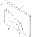
図1から図6は本発明の実施形態を示し、図1はファイル等の保持具を収容部の内面に付設したキャビネットの一部破断斜視図、図2はファイル等の保持具の一部を破断した斜視図、図3はファイル等の保持具の要部の拡大断面図、図4はファイル等の保持具の要部の拡大平面図、図5はファイル等を保持する際の保持具の要部の断面図、図6はファイル等を保護する保護カバーの一部破断斜視図である。
Hereinafter, embodiments of the present invention will be described with reference to the drawings.
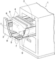
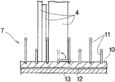
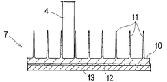
1 to 6 show an embodiment of the present invention. FIG. 1 is a partially cutaway perspective view of a cabinet in which a holder for a file or the like is attached to the inner surface of the accommodating portion, and FIG. 2 is a part of the holder for a file or the like. FIG. 3 is an enlarged cross-sectional view of a main part of a holder such as a file, FIG. 4 is an enlarged plan view of a main part of the holder such as a file, and FIG. 5 is a view of the holder when holding a file or the like. FIG. 6 is a partially cutaway perspective view of a protective cover for protecting a file or the like.
図1に示すように、このキャビネット(1)には、収容具である抽斗(2)が上下2段に設けてある。この抽斗(2)内の収容部(3)には、上方から背表紙を一覧できるように、ファイル等(4)が表面を垂直状態にして収容してある。なお、この実施形態では収容具としてキャビネット(1)の抽斗(2)を用いた場合について説明するが、本発明の収容具は、机の抽斗や本棚など、他の構造や形状の収容具であってもよく、その段数も特定のものに限定されない。 As shown in FIG. 1, the cabinet (1) is provided with a drawer (2) as a container in two upper and lower stages. In the storage portion (3) in the drawer (2), a file or the like (4) is stored with its surface vertical so that the spine can be listed from above. In addition, although this embodiment demonstrates the case where the drawer (2) of the cabinet (1) is used as a container, the container of this invention is a container of other structures and shapes, such as a desk drawer and a bookshelf. There may be, and the number of stages is not limited to a specific one.
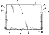
上記の抽斗(2)内の収容部(3)には、底面(5)とこれに隣接する左右の垂直な側面(6)とに、それぞれファイル等の保持具(7)が固定してある。上記の収容部(3)内に収容された上記のファイル等(4)は、下端縁(8)と左右両側端縁(9)とがこれらの保持具(7)に係止された状態となっている。このため、キャビネット(1)の抽斗(2)を開閉した際の衝撃を受けても、各端縁(8・9)が収容部(3)の内面に対し移動することがなく、従って、ファイル等(4)は倒れたり傾斜したりせずに、垂直状態に保持される。 In the housing (3) in the drawer (2), a holder (7) such as a file is fixed to the bottom surface (5) and the left and right vertical side surfaces (6) adjacent to the bottom surface (5). . The file etc. (4) housed in the housing part (3) has a state in which the lower end edge (8) and the left and right end edges (9) are engaged with these holders (7). It has become. For this reason, even if it receives an impact when the drawer (2) of the cabinet (1) is opened and closed, each end edge (8, 9) does not move with respect to the inner surface of the housing part (3). Etc. (4) is held in a vertical state without falling or tilting.
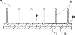
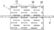
図2に示すように、上記の保持具(7)は、平面状の基材(10)と、この面状基材(10)の上面に多数立設した針状体(11)とを備える。上記の面状基材(10)の下面には、接着剤層(12)を介してシート状の磁石(13)からなる固定手段が設けてある。 As shown in FIG. 2, the holder (7) includes a planar base material (10) and a plurality of needle-like bodies (11) standing on the upper surface of the planar base material (10). . On the lower surface of the planar substrate (10), fixing means comprising a sheet-like magnet (13) is provided via an adhesive layer (12).
上記の面状基材(10)は、特定の材質に限定されず、例えば合成樹脂繊維による織布などで構成されるが、他の材質であってもよく、複数の材料を組み合わせてもよい。上記の接着剤層(12)は、上記の面状基材(10)に上記のシート状磁石(13)を固定できるものであればよく、特定の材質に限定されないが、例えば水性エマルジョンタイプの接着剤を用いると環境にやさしく、好ましい。 The planar substrate (10) is not limited to a specific material, and is composed of, for example, a woven fabric made of synthetic resin fiber, but may be other materials or a combination of a plurality of materials. . The adhesive layer (12) is not limited to a specific material as long as it can fix the sheet-like magnet (13) to the planar base material (10). Use of an adhesive is preferable because it is environmentally friendly.
なお、この実施形態では固定手段(13)としてシート状の磁石を用いたので、上記の収容部(3)がスティール製などの磁性体であると、上記の面状基材(10)をこの収容部(3)の内面へ簡単に且つ着脱可能に固定できて好ましい。しかし本発明では、例えば接着剤層(12)を固定手段として用いてもよく、この場合は収容部の内面が磁性体であるか否かにかかわらず、上記の面状基材(10)を離脱不能に固定することができる。 In this embodiment, since a sheet-like magnet is used as the fixing means (13), the above-described planar base material (10) is attached to the above-mentioned accommodation part (3) by using a magnetic material such as steel. It is preferable that it can be easily and detachably fixed to the inner surface of the accommodating portion (3). However, in the present invention, for example, the adhesive layer (12) may be used as a fixing means, and in this case, the planar base material (10) is used regardless of whether the inner surface of the housing portion is a magnetic body or not. Can be fixed so that it cannot be detached.
上記の針状体(11)は、例えばポリエチレン樹脂やポリプロピレン樹脂など、弾性変形可能な軟質の合成樹脂材料で、例えば直径が0.5〜1.0mm程度で、長さが1〜20mm、好ましくは5〜15mmの棒状に形成してある。この針状体(11)は、保持されるファイル等(4)の表面と並行な方向に沿って面状基材(10)上面へ複数本を並べてあり、この複数本からなる針状体(11)の列を、上記のファイル等(4)の厚さ方向へ間隔を隔てて複数配置してある。この針状体(11)同士間に挿入されたファイル等(4)は、その端縁(8)の両側から針状体(11)で挟持されるように保持される。 The needle-like body (11) is a soft synthetic resin material that can be elastically deformed, such as polyethylene resin or polypropylene resin, and has a diameter of about 0.5 to 1.0 mm and a length of 1 to 20 mm, preferably Is formed in a bar shape of 5 to 15 mm. A plurality of needle-like bodies (11) are arranged on the upper surface of the planar substrate (10) along a direction parallel to the surface of the file etc. (4) to be held. A plurality of rows 11) are arranged at intervals in the thickness direction of the above file etc. (4). The file or the like (4) inserted between the needle-like bodies (11) is held so as to be sandwiched between the needle-like bodies (11) from both sides of the end edge (8).
図3に示すように、上記の針状体(11)は、2本一組として両針状体(11)の下部同士が連結部(14)で連結してあり、この連結部(14)が上記の面状基材(10)に織り込んである。上記の針状体(11)は面状基材(10)に対して略直交方向に立設してあり、従って、針状体(11)同士の間隔は、上記の連結部(14)の長さにより、例えば5〜20mmに設定される。なお、この針状体(11)の先端は、球面状に形成してある。 As shown in FIG. 3, the needle-like body (11) has a pair of two needle-like bodies (11) connected to each other at the lower portion thereof by a connecting portion (14). Is woven into the planar substrate (10). The needle-like body (11) is erected in a substantially orthogonal direction with respect to the planar substrate (10) .Therefore, the interval between the needle-like bodies (11) is the same as that of the connecting portion (14). For example, it is set to 5 to 20 mm depending on the length. Note that the tip of the needle-like body (11) is formed in a spherical shape.
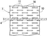
一方、図4に示すように、上記の2本一組の針状体(11)は、上記の連結部(14)が平面視で千鳥状に配置してあり、従って個々の針状体(11)は、保持されるファイル等(4)の厚さ方向にも並べてある。このとき、ファイル等(4)の厚さ方向の針状体(11)同士の間隔は、ファイル等(4)の表面と並行な方向の間隔よりも狭く、例えば1〜10mmに設定され、好ましくは2〜8mmに設定される。 On the other hand, as shown in FIG. 4, the pair of needle-like bodies (11) has the connecting portions (14) arranged in a staggered manner in a plan view. 11) is also arranged in the thickness direction of the file etc. (4) to be held. At this time, the interval between the needle-like bodies (11) in the thickness direction of the file (4) is narrower than the interval in the direction parallel to the surface of the file (4), and is preferably set to 1 to 10 mm, for example. Is set to 2-8 mm.
上記の針状体(11)は、弾性変形可能な軟質の合成樹脂材料で形成されているうえ、上記の連結部(14)での回動も可能であるので、面状基材(10)に沿った方向へ個別に姿勢を変更することができる。このため、例えば図5に示すように、針状体(11)同士の間隔よりも厚いファイル等(4)を収容する場合には、このファイル等(4)の端縁(8)に対面する一部の針状体(11)のみが面状基材(10)に沿った方向へ倒れて、ファイル等(4)の挿入の邪魔にならない。そして、この倒れた針状体(11)の両側に位置する針状体(11)により、この厚いファイル等(4)の端縁(8)が両側から挟持されて保持される。 The needle-like body (11) is formed of an elastically deformable soft synthetic resin material and can be rotated at the connecting portion (14). The posture can be individually changed in the direction along the line. Therefore, for example, as shown in FIG. 5, when a file (4) thicker than the interval between the needles (11) is accommodated, it faces the edge (8) of the file (4). Only some of the needle-like bodies (11) fall in the direction along the planar base material (10) and do not interfere with the insertion of the file (4). And the edge (8) of this thick file etc. (4) is clamped and held from both sides by the needle-like body (11) located on both sides of this fallen needle-like body (11).
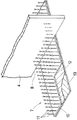
なお、上記のファイル等(4)は、例えばノートなどの場合、背表紙が上側に配置され、綴じられていない部位、いわゆる小口が収容部(3)内で下側や左右両側に配置される。この場合、この綴じられていない部位の用紙間に、上記の針状体(11)が入り込む虞がある。そこでこれらのファイル等(4)は、例えば図6に示すように、下端縁(8)と少なくとも一方の側端縁(9)とに亘って、小口を纏めるための保護カバー(15)を装着したのち、前記の収容部(3)へ収容するのが好ましい。 In the file (4), for example, in the case of a notebook or the like, the spine is placed on the upper side, and the unbound portion, so-called fore edge, is placed on the lower side and the left and right sides in the storage unit (3). . In this case, there is a possibility that the needle-like body (11) may enter between the sheets of the unbound portion. Therefore, for example, as shown in FIG. 6, these files and the like (4) are provided with a protective cover (15) for gathering a small edge over the lower edge (8) and at least one side edge (9). Then, it is preferable to accommodate in the said accommodating part (3).
上記の保護カバー(15)は、例えばL字形の2枚の合成樹脂製シート(16)を重ね合わせてあり、外側の2辺で両シート(16・16)を互いに接合してある。各シート(16)の内面は摩擦抵抗の大きい材質、例えばシリコンゴムなどでコーティングしてある。このため、この保護カバー(15)をファイル等(4)に装着すると、容易に滑り落ちることがない。そしてこの保護カバー(15)により小口が纏められているので、ファイル等(4)は各用紙にバラけることがなく、収容部(3)内への出し入れを容易に行うことができる。 The protective cover (15) has, for example, two L-shaped synthetic resin sheets (16) overlapped, and the two sheets (16, 16) are joined to each other on the outer two sides. The inner surface of each sheet (16) is coated with a material having a high frictional resistance, such as silicon rubber. For this reason, when this protective cover (15) is attached to a file or the like (4), it does not slide down easily. Since the forehead is gathered by the protective cover (15), the file (4) is not scattered on each sheet, and can be easily put in and out of the storage portion (3).
上記の実施形態で説明したファイル等の保持具やこれを用いた収容具は、本発明の技術的思想を具体化するために例示したものであり、各部材の形状や構造、寸法、配置などをこの実施形態のものに限定するものではなく、本発明の特許請求の範囲内において種々の変更を加え得るものである。 The holding device such as a file described in the above embodiment and the storage device using the same are illustrated to embody the technical idea of the present invention, and the shape, structure, dimensions, arrangement, etc. of each member However, the present invention is not limited to this embodiment, and various modifications can be made within the scope of the claims of the present invention.
例えば、上記の実施形態では、保持具(7)を収容部(3)の底面(5)や両側面(6)の一部に設けたが、本発明の保持具(7)は特定の大きさに限定されず、次のように変更することができる。
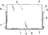
・図7に示す変形例1は、収容部(3)の内面のうち、底面(5)の一部と両側面(6)の略全面とに保持具(7)を固定したものである。
・図8に示す変形例2は、収容部(3)の内面のうち、底面(5)と一方の側面(6)とにのみ保持具(7)を固定したものである。
For example, in the above embodiment, the holder (7) is provided on a part of the bottom surface (5) and both side surfaces (6) of the housing part (3). However, the present invention is not limited to this, and can be changed as follows.
-The
-The
上記の実施形態では、針状体(11)を面状基材(10)と略垂直方向に立設して高さを揃え、これらの針状体(11)を、保持されるファイル等(4)の表面に並行な方向と厚さ方向とに並べて配置した。しかし本発明の針状体(11)は、例えば次のように変更することができる。
・図9に示す変形例3は、針状体(11)をファイル等(4)の厚さ方向へ、千鳥状に配置したものである。
・図10に示す変形例4は、2本一組の針状体(11)の基部を互いに連結してV字状に形成し、各針状体(11)を面状基材(10)に対し傾斜させたものである。即ち、各針状体(11)の基部は連結部(14)を構成し、面状基材(10)に織り込まれている。
・図11に示す変形例5は、針状体(11)の高さを1列ごとに異ならせるとともに、1列置きに高さを揃えたものである。この場合には、厚いファイル等(4)を保持する際に、高さの低い針状体(11)を面状基材(10)に沿って変形させればよいので、ファイル等(4)を容易に挿入することができる。
In the above-described embodiment, the needle-like body (11) is erected in a substantially vertical direction with the planar base material (10) so as to have a uniform height, and these needle-like bodies (11) are held in a file or the like ( It was arranged side by side in the direction parallel to the surface of 4) and the thickness direction. However, the needle-like body (11) of the present invention can be modified as follows, for example.
-The
In the fourth modification shown in FIG. 10, the bases of a pair of needle-like bodies (11) are connected to each other to form a V shape, and each needle-like body (11) is formed into a planar substrate (10). It is inclined with respect to. That is, the base of each needle-like body (11) constitutes a connecting portion (14) and is woven into the planar substrate (10).
In
上記の実施形態では、面状基材(10)を織布で形成して、針状体(11)をこの面状基材(10)に織りこませた。しかし本発明の面状基材(10)や針状体(11)は特定の材質のものに限定されず、例えば次のように変更することができる。
・図12に示す変形例は、面状基材(10)と針状体(11)を合成樹脂材料で一体に形成したものである。なお、針状体(11)は先細形状に形成してあり、厚いファイル等(4)を収容する場合に、容易に弾性変形するようにしてある。
In the above embodiment, the planar substrate (10) is formed of a woven fabric, and the needle-like body (11) is woven into the planar substrate (10). However, the planar substrate (10) and the needle-like body (11) of the present invention are not limited to specific materials, and can be modified as follows, for example.
In the modification shown in FIG. 12, the planar substrate (10) and the needle-like body (11) are integrally formed of a synthetic resin material. The needle-like body (11) is formed in a tapered shape, and is easily elastically deformed when a thick file or the like (4) is accommodated.
上記の実施形態では、キャビネットの抽斗内でファイル等を、厚さ方向が前後方向となるように配置するため、上記の保持具は底面と側面に設けた。しかし本発明の収容具は、収容部の底面とこれに隣接する垂直面に保持具を設けてあればよく、抽斗内の底面と前後の側面に保持具を設けて、ファイル等を厚さ方向が左右方向となるように収容してもよい。また、上記の収容具が本棚である場合には、収容部の底面と背面とに上記の保持具が固定される。 In the above embodiment, the holders are provided on the bottom surface and the side surface in order to arrange the files and the like in the drawer of the cabinet so that the thickness direction is the front-rear direction. However, the container of the present invention only needs to be provided with holders on the bottom surface of the storage part and the vertical surface adjacent thereto, and the holders are provided on the bottom surface and the front and back side surfaces in the drawer, so May be accommodated in the left-right direction. Moreover, when said container is a bookshelf, said holder is fixed to the bottom face and back surface of a accommodating part.
その他、上記の固定手段はシート状磁石に限定されず、さらには面状基材に固定手段を設けずに、両面テープなどによりこの面状基材を収容部の内面に固定することも可能である。また、上記の針状体の寸法や形状、配置間隔などは、上記の実施形態のものに限定されないことは言うまでもない。 In addition, the fixing means is not limited to a sheet-like magnet, and it is also possible to fix the planar base material to the inner surface of the housing portion with a double-sided tape or the like without providing the fixing means on the planar base material. is there. Moreover, it cannot be overemphasized that the dimension of the said acicular body, a shape, arrangement | positioning space | interval, etc. are not limited to the thing of said embodiment.
本発明のファイル等の保持具およびこれを用いた収容具は、ファイル等を確実に立てた状態で保持でき、しかも収容空間を十分に生かして多量のファイルを容易に収容できるので、キャビネットや机の抽斗、本棚、本立など、各種の収容具に好適に用いられる。 The holder for a file and the like and the holder using the same according to the present invention can hold a file or the like in a state in which the file or the like is erected, and can easily accommodate a large amount of files by fully utilizing the storage space. It is suitably used for various storage devices such as drawers, bookshelves, and book stands.
2…収容具(抽斗)
3…収容部
4…ファイル等
5…収容部(3)の底面
6…収容部(3)の垂直面(側面)
7…保持具
10…面状基材
11…針状体
13…固定手段(シート状磁石)
2… Container (drawer)
DESCRIPTION OF
7 ... holding tool
10 ... Planar substrate
11 ... acicular body
13 ... Fixing means (sheet magnet)
Claims (16)
平面状の基材(10)と、この面状基材(10)の上面に多数立設した針状体(11)とを備えることを特徴とする、ファイル等の保持具。 A holding tool for holding a file (4) in a vertical state in the storage part (3) of the storage tool (2),
A holder for a file or the like, comprising: a planar substrate (10); and a plurality of needle-like bodies (11) erected on the upper surface of the planar substrate (10).
上記の針状体(11)は、2本一組として両針状体(11・11)の下部同士を連結部(14)で連結し、この連結部(14)を上記の面状基材(10)に織り込んである、請求項1から7のいずれか1項に記載のファイル等の保持具。 At least the upper surface of the planar substrate (10) is composed of a woven fabric,
The needle-like body (11) is a pair of two, and the lower portions of both needle-like bodies (11, 11) are connected to each other by a connecting portion (14), and the connecting portion (14) is connected to the planar substrate. The holder for a file or the like according to any one of claims 1 to 7, which is woven into (10).
収容部(3)内面のうちの底面(5)と、この底面(5)に隣接する少なくとも1つの垂直面(6)とに、上記の請求項1から13のいずれか1項に記載のファイル等の保持具(7)を固定したことを特徴とする、ファイル等の収容具。 A storage device comprising a storage portion (3) and storing files (4) in a vertical state in the storage portion (3),
The file according to any one of claims 1 to 13, wherein a bottom surface (5) of the inner surface of the accommodating portion (3) and at least one vertical surface (6) adjacent to the bottom surface (5) are provided. A storage device for a file or the like, characterized by fixing a holder (7) such as a file.
Priority Applications (1)
| Application Number | Priority Date | Filing Date | Title |
|---|---|---|---|
| JP2007286069A JP5031519B2 (en) | 2007-11-02 | 2007-11-02 | Holder for files, etc. and container using the same |
Applications Claiming Priority (1)
| Application Number | Priority Date | Filing Date | Title |
|---|---|---|---|
| JP2007286069A JP5031519B2 (en) | 2007-11-02 | 2007-11-02 | Holder for files, etc. and container using the same |
Publications (2)
| Publication Number | Publication Date |
|---|---|
| JP2009113236A true JP2009113236A (en) | 2009-05-28 |
| JP5031519B2 JP5031519B2 (en) | 2012-09-19 |
Family
ID=40780929
Family Applications (1)
| Application Number | Title | Priority Date | Filing Date |
|---|---|---|---|
| JP2007286069A Expired - Fee Related JP5031519B2 (en) | 2007-11-02 | 2007-11-02 | Holder for files, etc. and container using the same |
Country Status (1)
| Country | Link |
|---|---|
| JP (1) | JP5031519B2 (en) |
Cited By (1)
| Publication number | Priority date | Publication date | Assignee | Title |
|---|---|---|---|---|
| CN110481200A (en) * | 2019-08-07 | 2019-11-22 | 格力电器(武汉)有限公司 | A kind of project cost accounting bill storage device |
Citations (4)
| Publication number | Priority date | Publication date | Assignee | Title |
|---|---|---|---|---|
| JPS52135225U (en) * | 1976-04-06 | 1977-10-14 | ||
| JPS5836180U (en) * | 1981-09-02 | 1983-03-09 | 岸 宏昭 | memo holder |
| JPH0210810Y2 (en) * | 1987-10-07 | 1990-03-16 | ||
| JPH10329469A (en) * | 1997-05-30 | 1998-12-15 | Toppan Forms Co Ltd | File box |
-
2007
- 2007-11-02 JP JP2007286069A patent/JP5031519B2/en not_active Expired - Fee Related
Patent Citations (4)
| Publication number | Priority date | Publication date | Assignee | Title |
|---|---|---|---|---|
| JPS52135225U (en) * | 1976-04-06 | 1977-10-14 | ||
| JPS5836180U (en) * | 1981-09-02 | 1983-03-09 | 岸 宏昭 | memo holder |
| JPH0210810Y2 (en) * | 1987-10-07 | 1990-03-16 | ||
| JPH10329469A (en) * | 1997-05-30 | 1998-12-15 | Toppan Forms Co Ltd | File box |
Cited By (1)
| Publication number | Priority date | Publication date | Assignee | Title |
|---|---|---|---|---|
| CN110481200A (en) * | 2019-08-07 | 2019-11-22 | 格力电器(武汉)有限公司 | A kind of project cost accounting bill storage device |
Also Published As
| Publication number | Publication date |
|---|---|
| JP5031519B2 (en) | 2012-09-19 |
Similar Documents
| Publication | Publication Date | Title |
|---|---|---|
| US5217124A (en) | Clip-on divider device for supporting and organizing objects on a shelf | |
| US5765695A (en) | Wall mounted compact disc case holder assembly | |
| US20020104811A1 (en) | Desktop organizer | |
| WO1997006961A1 (en) | File management system | |
| JPH06507582A (en) | Device for supporting ring binders | |
| US4793633A (en) | Device for supporting bound material | |
| JP5031519B2 (en) | Holder for files, etc. and container using the same | |
| US6739451B2 (en) | Method and apparatus for the storage, display and retrieval of flat media | |
| JP4309059B2 (en) | Sheet bundle dispenser | |
| JP2020185273A (en) | Bookrest | |
| US1736908A (en) | Periodical holder | |
| JP6772688B2 (en) | Accessory storage case | |
| US20110042532A1 (en) | Pad hanger | |
| US20030006205A1 (en) | Compact disc holder and organizer | |
| JP4975732B2 (en) | Upright memo paper holder | |
| JP5022119B2 (en) | Storage file | |
| KR200323346Y1 (en) | A copy holder | |
| KR20080001636U (en) | Desktop calendar | |
| US20050206283A1 (en) | Computer accessory | |
| JP3156184U (en) | Document holder | |
| US20060124569A1 (en) | Alignment system and method for vertically stored objects | |
| JPH0826367A (en) | Compact disk holder | |
| KR101817190B1 (en) | Bookshelf with dividing board for page of a book | |
| RU26275U1 (en) | CD CONTAINER | |
| KR200441618Y1 (en) | Desktop Diary |
Legal Events
| Date | Code | Title | Description |
|---|---|---|---|
| A621 | Written request for application examination |
Free format text: JAPANESE INTERMEDIATE CODE: A621 Effective date: 20100601 |
|
| A977 | Report on retrieval |
Free format text: JAPANESE INTERMEDIATE CODE: A971007 Effective date: 20120319 |
|
| A131 | Notification of reasons for refusal |
Free format text: JAPANESE INTERMEDIATE CODE: A131 Effective date: 20120327 |
|
| A521 | Written amendment |
Free format text: JAPANESE INTERMEDIATE CODE: A523 Effective date: 20120521 |
|
| TRDD | Decision of grant or rejection written | ||
| A01 | Written decision to grant a patent or to grant a registration (utility model) |
Free format text: JAPANESE INTERMEDIATE CODE: A01 Effective date: 20120605 |
|
| A01 | Written decision to grant a patent or to grant a registration (utility model) |
Free format text: JAPANESE INTERMEDIATE CODE: A01 |
|
| A61 | First payment of annual fees (during grant procedure) |
Free format text: JAPANESE INTERMEDIATE CODE: A61 Effective date: 20120627 |
|
| R150 | Certificate of patent or registration of utility model |
Ref document number: 5031519 Country of ref document: JP Free format text: JAPANESE INTERMEDIATE CODE: R150 Free format text: JAPANESE INTERMEDIATE CODE: R150 |
|
| FPAY | Renewal fee payment (event date is renewal date of database) |
Free format text: PAYMENT UNTIL: 20150706 Year of fee payment: 3 |
|
| S531 | Written request for registration of change of domicile |
Free format text: JAPANESE INTERMEDIATE CODE: R313531 |
|
| R350 | Written notification of registration of transfer |
Free format text: JAPANESE INTERMEDIATE CODE: R350 |
|
| R250 | Receipt of annual fees |
Free format text: JAPANESE INTERMEDIATE CODE: R250 |
|
| R250 | Receipt of annual fees |
Free format text: JAPANESE INTERMEDIATE CODE: R250 |
|
| R250 | Receipt of annual fees |
Free format text: JAPANESE INTERMEDIATE CODE: R250 |
|
| R250 | Receipt of annual fees |
Free format text: JAPANESE INTERMEDIATE CODE: R250 |
|
| R250 | Receipt of annual fees |
Free format text: JAPANESE INTERMEDIATE CODE: R250 |
|
| LAPS | Cancellation because of no payment of annual fees |