JP2009113122A - Impact tool - Google Patents
Impact tool Download PDFInfo
- Publication number
- JP2009113122A JP2009113122A JP2007285395A JP2007285395A JP2009113122A JP 2009113122 A JP2009113122 A JP 2009113122A JP 2007285395 A JP2007285395 A JP 2007285395A JP 2007285395 A JP2007285395 A JP 2007285395A JP 2009113122 A JP2009113122 A JP 2009113122A
- Authority
- JP
- Japan
- Prior art keywords
- cylinder case
- cover
- elastic body
- impact
- impact tool
- Prior art date
- Legal status (The legal status is an assumption and is not a legal conclusion. Google has not performed a legal analysis and makes no representation as to the accuracy of the status listed.)
- Granted
Links
Images


Abstract
Description
本発明は、ハンマ等の打撃工具におけるシリンダケース外周部を覆うカバーに関するものである。 The present invention relates to a cover that covers an outer peripheral portion of a cylinder case in an impact tool such as a hammer.
従来の打撃工具を図6を用いて説明する。 A conventional striking tool will be described with reference to FIG.
図6は、従来のハンマ1である。ハンマ1はハウジング2を有しており、ハンドル3がハウジング2に接続されている。ハウジング2内部には図示しないモータが内蔵されている。ハンドル3は、操作可能なスイッチ5及びハンドル3より延びる電源コード4有している。
FIG. 6 shows a conventional hammer 1. The hammer 1 has a
スイッチを操作すると、図示しないモータへと給電が行われ、モータが回転する。モータの回転により、クランク10が回転する。クランク10の回転は、コネクティングロッド11の往復動へと変換され、コネクティングロッド11に接続されている閉塞壁12が往復動する。閉塞壁12の往復動によって、空気室13内部の圧力が変動する。空気室13内部の圧力が高いときに、打撃子14は打撃され、先端工具8側へと移動する。この移動によって、打撃子14と略当接している中間子15が打撃される。打撃された中間子15は、先端工具8へとその打撃を伝達し、先端工具8は、図示しない被削材を打撃することによって、所定の仕事を行う。
When the switch is operated, power is supplied to a motor (not shown), and the motor rotates. The
ここで、ハンマ1は、打撃子14、中間子15又は先端工具8の移動又は打撃によって、衝撃又は振動を受けるものであった。また、先端工具8が図示しない被削材を打撃することによる衝撃によって、ハンマ1は、衝撃又は振動を受けるものであった。
Here, the hammer 1 is subjected to an impact or vibration due to the movement or striking of the
さらに、ハンマ1内部で発生した熱が、打撃子14、中間子15、空気室13などを略覆うシリンダケース19へと伝達し、作業者がシリンダケース19付近を把持することが困難であることがあった。そこで、シリンダケース19の外周を樹脂やゴム製のカバー20で覆う構成としていた。
Furthermore, the heat generated inside the hammer 1 is transmitted to the
上記したように、ハンマ1は、衝撃を受け又は振動するものであるが、その振動は、先端工具8の軸方向へと伝達するものであり、効果的に衝撃又は振動を抑制することが必要であった。
As described above, the hammer 1 receives or vibrates an impact, but the vibration is transmitted in the axial direction of the
また、ハンマ1内部で発生した熱をシリンダケース19カバー20へと伝達することを効果的に抑制する必要があった。
Further, it is necessary to effectively suppress the heat generated in the hammer 1 from being transmitted to the
本発明の目的は、上記従来の必要性を満たし、シリンダケースを把持して作業する際の操作性を向上させた打撃工具を提供することである。 An object of the present invention is to provide a striking tool that satisfies the above conventional needs and has improved operability when gripping and operating a cylinder case.
上記目的は、先端工具と、モータと、該モータの回転を往復運動に変換し、前記先端工具を打撃する打撃機構部と、該打撃機構部を略収納するシリンダケースと、該シリンダケース外周部を覆うカバーとを有する打撃工具において、前記シリンダケース外周部と前記カバー内周部の間に、前記シリンダケースが前記カバーに対して相対移動した際に変形する弾性体を設けたことを特徴とする打撃工具により達成することができる。 The object is to provide a tip tool, a motor, a striking mechanism portion that transforms the rotation of the motor into a reciprocating motion and strikes the tip tool, a cylinder case that substantially stores the striking mechanism portion, and an outer peripheral portion of the cylinder case In the impact tool having a cover for covering, an elastic body that deforms when the cylinder case moves relative to the cover is provided between the cylinder case outer periphery and the cover inner periphery. Can be achieved with a striking tool.
本発明の打撃工具によれば、シリンダケースとカバーの間に弾性体を設ける構成としたために、弾性体によってシリンダケースからカバーへと伝わる熱が減少するために、シリンダケースからカバーへと熱が伝達することを抑制することができる。また、シリンダケースとカバーの間に弾性体を設ける構成としたために、弾性体によってシリンダケースからカバーへと伝達する衝撃又は振動が減少するために、作業者へ衝撃又は振動の伝達が抑制される。 According to the striking tool of the present invention, since the elastic body is provided between the cylinder case and the cover, heat transmitted from the cylinder case to the cover by the elastic body is reduced, so that heat is transferred from the cylinder case to the cover. Transmission can be suppressed. Further, since the elastic body is provided between the cylinder case and the cover, the impact or vibration transmitted from the cylinder case to the cover by the elastic body is reduced, so that transmission of the shock or vibration to the operator is suppressed. .
本発明打撃工具の一実施形態を図1〜図5を用いて説明する。 An embodiment of the impact tool of the present invention will be described with reference to FIGS.
図1に本発明の実施の打撃工具の一例であるハンマ1の概観図を示す。図2に本発明の実施のハンマの要部断面図を示す。図3に本発明のハンマの所定の作業の際に動作しているハンマの要部断面図を示す。図4に本発明の実施を構成するハンマのシリンダケースを示す。図5に図2のÅ−Å線断面図を示す。 FIG. 1 shows an overview of a hammer 1 which is an example of an impact tool according to the present invention. FIG. 2 shows a cross-sectional view of the main part of a hammer according to the present invention. FIG. 3 shows a cross-sectional view of the main part of the hammer operating during a predetermined operation of the hammer of the present invention. FIG. 4 shows a hammer cylinder case constituting the embodiment of the present invention. FIG. 5 is a cross-sectional view taken along the line Å-Å in FIG.
図1に示すように、本発明のハンマ1は、ハウジング2及びハンドル3を有している。ハンドル3は、縦に長い構造をしており、ハンドル3とその上端部付近に設けられる作業者がハウジング2内に設けられる図示しないモータに給電可能なスイッチ5と、スイッチ5をオン状態に維持可能な補助スイッチ5Aと、外部の電源より給電可能な電源コード4とを有する。ハンドル3は、作業者が把持できるようになっており、把持した手でスイッチ5を操作可能となっている。また、その上端部6及び下端部7でハウジング2に接続されている。上端部6内部には図示しない弾性体が設けられており、また、下端部7には、図示しない弾性体が設けられている。
As shown in FIG. 1, the hammer 1 of the present invention has a
ハウジング2は、図示しないモータを内蔵する。ハウジング2は、打撃機構部の一部を内部に収納する。また、カバー20が設けられており、ハンマ1の外周形状となる。
The
カバー20の先端工具8側には、先端工具保持部18が設けられており、先端工具保持部18は、先端工具8保持可能である。なお、図1では、先端工具8が先端工具保持部18に保持されている。
A tip
図2に、図1の要部断面図を示す。 FIG. 2 shows a cross-sectional view of the main part of FIG.
図示しないモータには、ギアがあり、ギアによって、クランク10が回転可能になっている。クランク10は、コネクティングロッド11に接続されており、クランク10の回転は、コネクティングロッド11の往復動に変換される。コネクティングロッド11は、閉塞壁12に接続されている。閉塞壁12は、シリンダ16と共に空気室13の一部を構成する。空気室13は、閉塞壁12の往復動によってその内部の圧力が変動する。空気室13の反閉塞壁12側には打撃子14が設けられている。また、打撃子14は中間子15と略当接している。なお、打撃子14及び中間子15は、シリンダに略覆われている。シリンダ16には、ボール17が設けられており工具保持部18を空気室13側へと移動させることによって、ボール17が空気室13側へと移動することによって、ボール17と先端工具8との係合が外れるようになっており、先端工具8を先端工具保持部位18より取り外すことができるようになっている。
A motor (not shown) has a gear, and the
シリンダ16の少なくとも一部を覆うようにシリンダケース19が設けられている。なお、図5に示すように、シリンダ16及びシリンダケース19は、略中空の形状をしている。
A
シリンダケース19の外周部には、図4に示すように、緩やかな斜面19A1、19A2、19A3・・・が設けられる。また、急な斜面19B1、19B2、19B3・・・が設けられる。なお、図4に示すように、緩やかな斜面と急な斜面は交互に設けられている。例えば、19A1と19B1の2つの斜面によって、シリンダケース19は凹部が形成される。また、例えば19B1と19A2の2つの斜面によって凸部が形成される。このように、6つの凸部と7つの凸部をシリンダケース19は有する。なお、図2に示すように、凹部及び凸部は、シリンダケース19の外周面に設けられている。
As shown in FIG. 4, gentle slopes 19A1, 19A2, 19A3,... Further, steep slopes 19B1, 19B2, 19B3... Are provided. As shown in FIG. 4, gentle slopes and steep slopes are alternately provided. For example, a recess is formed in the
凹部には、弾性体21が設けられている。弾性体21は、輪形状をしており、その断面は、図4に示すように円形である。なお、図4においては、例として弾性体21を一つのみ点線で図示した。弾性体21は、4つ設けられており、7つの凹部において一つおきに設けられている。弾性体21と一部で接するように外側にカバー20が設けらている。カバー20には、シリンダケース19と対応するように、緩やかな斜面及び急な斜面が設けられており、凹部および凸部が設けられている。シリンダケース19と同様に、一つおきに弾性体が凹部に設けられている。なお、シリンダケースは、図示しない2つ割り構造となっている。すなわち、図示しない断面で2つの部材が接合されている。なお、ハンマ1をを組み立てる場合には、まずシリンダケース19に弾性体21を4つ取付け、その後に、その外周部からカバー20の第1の部材及び第2の部材で覆い、図示しない接合部でその第1の部材及び第2の部材を接合するものである。
An
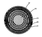
図5に図2のA−A線付近断面図を示す。 FIG. 5 shows a cross-sectional view of the vicinity of the line AA in FIG.
打撃子14の外側には、シリンダ16が設けられており打撃子14とシリンダ16の間は摺動可能となっている。シリンダケース19の外周面の一部に接するように弾性体21が設けられており、また、カバー20の内周部の一部に接するように弾性体21が設けられている。
A
本発明の実施におけるハンマ1の動作について説明する。 The operation of the hammer 1 in the implementation of the present invention will be described.
図2の電源コード4よりハンマ1へと給電を行い、スイッチ5を作業者が操作すると、スイッチ5がオンになり、ハウジング2内部に設けられる図示しないモータに給電が行われる。また、補助スイッチ5Aによってハンマの打撃をオン状態に保持する。これによって、スイッチ5を操作し続けなくとも、スイッチ5がオン状態に維持することができる。なお、スイッチ5と補助スイッチ5Aは、スイッチ5を操作したオン状態で補助スイッチ5Aを操作することによって、スイッチ5をオン状態にするように補助スイッチ5Aとスイッチ5とが係合可能に設けられている。モータは給電によって、回転し、モータの回転は、モータの軸上に設けられる図示しないギアと係合するギアによって、クランク10へと伝達される。クランク10が回転すると、クランク10に接続されるコネクティングロッド11が先端工具8の軸方向へと往復動する。コネクティングロッド11が往復動すると、コネクティングロッド11の反クランク10端部に設けられ、シリンダ16を略閉塞する閉塞壁12が往復動する。この往復動によって、空気室13内部の空気が圧力変動を起こす。この圧力が高い場合には、空気室13の反閉塞壁12側であってシリンダ16の内側に設けられる打撃子14が先端工具8方向へと衝撃によって移動する。この移動によって、打撃子14と略当接するように設けられる中間子15は、先端工具8方向へと移動する。中間子15は、先端工具8と略当接するように設けられており、先端工具8は図示しない被削材へと所定の作業を行う。
When power is supplied to the hammer 1 from the power cord 4 in FIG. 2 and the operator operates the
クランク10の回転、コネクティングロッド11の往復動、閉塞壁12の往復動、空気室13の圧力変動、打撃子14の移動、中間子15の移動、先端工具8の移動、先端工具8の被削材よりの反力等によって、ハンマ1は、略先端工具8の軸方向に衝撃又は振動を受ける。
Rotation of the
作業者は、ハンマをハンドル3及びカバー20によって把持する。この際に、ハンドル3とハウジング2の間である上端部6及び下端部7に前記のように弾性体が設けられているために、ハンドル3へと衝撃又は振動を伝わることが抑制される。
The operator holds the hammer with the
カバー20の内周面の一部と接するように略輪形状の断面が円形の弾性体21が設けられており、弾性体21よりもシリンダ16側には、シリンダケース19がシリンダ16を覆うように設けられている。
An
図3にハンマ1が衝撃又は振動を受けた際の様子を示す。 FIG. 3 shows a state when the hammer 1 is subjected to impact or vibration.
カバー20が、図2の状態に比してシリンダケース19及びハウジング2などに対して先端工具8方向へと移動している。また、弾性体21の断面が略円形ではない形へと変形している。これは、衝撃又は振動によって、シリンダケース19及びハウジング2などが反先端工具8側へと移動した際に、それに伴い、シリンダケース19の凹部とカバー20の凹部に挟むように設けられた弾性体21が変形することによって、衝撃又は振動を抑えることができる。なお、弾性体21は断面が円形をしているために、緩やかな斜面を転がるように圧縮されることによって、圧縮の初期には小さい衝撃又は振動を抑えることができ、圧縮が進むと徐々に大きい衝撃又は振動の吸収が行われるようになっている。そのため、衝撃又は振動の大きさに応じて、弾性体21が吸収できるようになっているために、作業者への負担が少ないようになっている。また、カバー20とシリンダケース19の間に弾性体21を設ける構成としたために、シリンダケース19からカバー20への熱の伝導が減少する。このため、カバー20を作業者が把持する際の作業性を向上することができる。
The
また、弾性体21が4個設けられる構成であるために、4個のそれぞれの弾性体21が衝撃又は振動を吸収することができ、衝撃を緩やかに吸収することができ、また、振動数が大きいものから小さいものまで効果的に吸収することができる。
In addition, since the four
なお、オン状態に維持可能な補助スイッチ5Aを設ける構成としたために、衝撃又は振動を吸収しながら、オン状態で連続して作業をすることができるために、作業の効率を上げることができる。 In addition, since it was set as the structure which provided 5 A of auxiliary switches which can be maintained in an ON state, since it can work continuously in an ON state, absorbing an impact or a vibration, work efficiency can be raised.
また、ハンドル3及びハウジング2の間である上端部6及び下端部7には弾性体が設けられる構成としたために、カバー20及びハンドル3を把持した際には、作業者へと伝わる衝撃又は振動をより効果的に抑制することができる。
In addition, since the upper end portion 6 and the lower end portion 7 between the
また、凹部は、シリンダケース19及びカバー20にそれぞれ7つ設けられているのにたいして弾性体21は4つしか設けられていない。このため、弾性体21によって、シリンダケース19からカバー20への熱の伝達が減少し、また、弾性体21が設けられていない凹部の間には、空気があるために、熱の伝達が減少するようになっている。このため、カバー20を作業者が把持する際に、熱によって把持することができなくなることを抑制することができる。
Further, although seven concave portions are provided in each of the
なお、本発明の一実施形態では、弾性体21を4つ設ける構成としたが、1つのみを設ける構成であっても本発明の効果を奏し得ることができる。
In addition, in one Embodiment of this invention, it was set as the structure which provides the four
また、本発明では、弾性体21を凹部に一つおきに設ける構成としたが、弾性体21を連続的に全ての凹部に7つ設ける構成であっても本願発明の効果を奏し得ることができる。
Further, in the present invention, every other
本願発明では、電源コードによって給電を行う構成としたが、繰り返し充電可能な充電池によって給電される構成であっても本願発明の効果を奏し得ることができる。 In this invention, although it was set as the structure which electrically feeds with a power cord, even if it is the structure electrically fed with the rechargeable battery which can be charged repeatedly, the effect of this invention can be show | played.
本願発明では、実施の構成として、打撃工具の例としてハンマによって発明を説明したが、先端工具軸方向の衝撃又は振動が起きる打撃工具であれば、例えばドリル、振動ドリル、ハンマドリルであっても本願発明の効果を奏し得ることができる。 In the present invention, the invention has been described with a hammer as an example of a striking tool as an embodiment. However, if the striking tool generates an impact or vibration in the axial direction of the tip tool, for example, a drill, a vibration drill, or a hammer drill may be used. The effects of the invention can be achieved.
1はハンマ、2はハウジング、3はハンドル、4は電源コード、5はスイッチ、8は先端工具、10はクランク、11はコネクティングロッド、12は閉塞壁、13は空気室、14は打撃子、15は中間子、16はシリンダ、17はボール、18は先端工具保持部、19はシリンダケース、20はカバー、21は弾性体である。
1 is a hammer, 2 is a housing, 3 is a handle, 4 is a power cord, 5 is a switch, 8 is a tip tool, 10 is a crank, 11 is a connecting rod, 12 is a blocking wall, 13 is an air chamber, 14 is a striker,
Claims (8)
モータと、
該モータの回転を往復運動に変換し、前記先端工具を打撃する打撃機構部と、
該打撃機構部を略収納するシリンダケースと、
該シリンダケース外周部を覆うカバーとを有する打撃工具において、
前記シリンダケース外周部と前記カバー内周部の間に、前記カバーが前記シリンダケースに対して相対移動した際に変形する弾性体を設けたことを特徴とする打撃工具。 A tip tool,
A motor,
A striking mechanism that transforms the rotation of the motor into a reciprocating motion and strikes the tip tool;
A cylinder case that substantially houses the striking mechanism;
In the impact tool having a cover that covers the outer periphery of the cylinder case,
An impact tool characterized in that an elastic body is provided between the outer periphery of the cylinder case and the inner periphery of the cover, which is deformed when the cover moves relative to the cylinder case.
該スイッチをオン状態に維持可能な補助スイッチを有することを特徴とする請求項1から請求項6までのいずれか1項記載の打撃工具。 The impact tool has an operable switch,
The impact tool according to any one of claims 1 to 6, further comprising an auxiliary switch capable of maintaining the switch in an ON state.
該ハンドルと打撃機構部との間には、弾性体が設けられていることを特徴とする請求項1から請求項7までのいずれか1項記載の打撃工具。 The impact tool has a handle that can be gripped by an operator,
The striking tool according to any one of claims 1 to 7, wherein an elastic body is provided between the handle and the striking mechanism.
Priority Applications (1)
| Application Number | Priority Date | Filing Date | Title |
|---|---|---|---|
| JP2007285395A JP5326258B2 (en) | 2007-11-01 | 2007-11-01 | Impact tool |
Applications Claiming Priority (1)
| Application Number | Priority Date | Filing Date | Title |
|---|---|---|---|
| JP2007285395A JP5326258B2 (en) | 2007-11-01 | 2007-11-01 | Impact tool |
Publications (2)
| Publication Number | Publication Date |
|---|---|
| JP2009113122A true JP2009113122A (en) | 2009-05-28 |
| JP5326258B2 JP5326258B2 (en) | 2013-10-30 |
Family
ID=40780838
Family Applications (1)
| Application Number | Title | Priority Date | Filing Date |
|---|---|---|---|
| JP2007285395A Expired - Fee Related JP5326258B2 (en) | 2007-11-01 | 2007-11-01 | Impact tool |
Country Status (1)
| Country | Link |
|---|---|
| JP (1) | JP5326258B2 (en) |
Cited By (1)
| Publication number | Priority date | Publication date | Assignee | Title |
|---|---|---|---|---|
| US10569405B2 (en) | 2014-10-29 | 2020-02-25 | Koki Holdings Co., Ltd. | Impact tool |
Citations (12)
| Publication number | Priority date | Publication date | Assignee | Title |
|---|---|---|---|---|
| DE716899C (en) * | 1940-06-06 | 1942-01-31 | Josef Ternes Dipl Ing | Jackhammer |
| US2451234A (en) * | 1944-11-20 | 1948-10-12 | Independent Pneumatic Tool Co | Compression member |
| JPS57100480U (en) * | 1980-12-09 | 1982-06-21 | ||
| JPS57126982U (en) * | 1981-01-29 | 1982-08-07 | ||
| JPS59102640U (en) * | 1982-12-28 | 1984-07-10 | オカダアイヨン株式会社 | Anti-vibration bracket for striking device |
| JPS61102484U (en) * | 1984-12-12 | 1986-06-30 | ||
| US5044254A (en) * | 1991-02-01 | 1991-09-03 | Coltene/Whaldent, Inc. | Reciprocating air motor |
| JPH055380U (en) * | 1991-07-10 | 1993-01-26 | 株式会社テイサク | Shock absorber for impact tool |
| JPH0825249A (en) * | 1994-07-12 | 1996-01-30 | Makita Corp | Vibrating tool and vibration isolating ring |
| JP2001062756A (en) * | 1999-08-10 | 2001-03-13 | Hilti Ag | Hand motor-driven combined hammer device |
| US20040094315A1 (en) * | 2002-11-18 | 2004-05-20 | Chen, Hsiu-Ju | Shock-absorbing structure for pneumatic tool |
| JP2005193354A (en) * | 2004-01-09 | 2005-07-21 | Hitachi Koki Co Ltd | Impact tool |
-
2007
- 2007-11-01 JP JP2007285395A patent/JP5326258B2/en not_active Expired - Fee Related
Patent Citations (12)
| Publication number | Priority date | Publication date | Assignee | Title |
|---|---|---|---|---|
| DE716899C (en) * | 1940-06-06 | 1942-01-31 | Josef Ternes Dipl Ing | Jackhammer |
| US2451234A (en) * | 1944-11-20 | 1948-10-12 | Independent Pneumatic Tool Co | Compression member |
| JPS57100480U (en) * | 1980-12-09 | 1982-06-21 | ||
| JPS57126982U (en) * | 1981-01-29 | 1982-08-07 | ||
| JPS59102640U (en) * | 1982-12-28 | 1984-07-10 | オカダアイヨン株式会社 | Anti-vibration bracket for striking device |
| JPS61102484U (en) * | 1984-12-12 | 1986-06-30 | ||
| US5044254A (en) * | 1991-02-01 | 1991-09-03 | Coltene/Whaldent, Inc. | Reciprocating air motor |
| JPH055380U (en) * | 1991-07-10 | 1993-01-26 | 株式会社テイサク | Shock absorber for impact tool |
| JPH0825249A (en) * | 1994-07-12 | 1996-01-30 | Makita Corp | Vibrating tool and vibration isolating ring |
| JP2001062756A (en) * | 1999-08-10 | 2001-03-13 | Hilti Ag | Hand motor-driven combined hammer device |
| US20040094315A1 (en) * | 2002-11-18 | 2004-05-20 | Chen, Hsiu-Ju | Shock-absorbing structure for pneumatic tool |
| JP2005193354A (en) * | 2004-01-09 | 2005-07-21 | Hitachi Koki Co Ltd | Impact tool |
Cited By (1)
| Publication number | Priority date | Publication date | Assignee | Title |
|---|---|---|---|---|
| US10569405B2 (en) | 2014-10-29 | 2020-02-25 | Koki Holdings Co., Ltd. | Impact tool |
Also Published As
| Publication number | Publication date |
|---|---|
| JP5326258B2 (en) | 2013-10-30 |
Similar Documents
| Publication | Publication Date | Title |
|---|---|---|
| JP5128998B2 (en) | Hand-held work tool | |
| JP6441588B2 (en) | Impact tool | |
| JP5361504B2 (en) | Impact tool | |
| US9463566B2 (en) | Auxiliary handle and reciprocating power tool having the same | |
| RU2477211C2 (en) | Impact tool | |
| US20120118598A1 (en) | Impact tool | |
| CN202021588U (en) | Electric hammer | |
| US20100206595A1 (en) | Auxiliary handle | |
| JP5436071B2 (en) | Work tools | |
| JP5326258B2 (en) | Impact tool | |
| JP4438638B2 (en) | Impact tool | |
| JP5356097B2 (en) | Impact tool | |
| JP2007175836A (en) | Striking tool | |
| JP6125392B2 (en) | Impact tool | |
| WO2017199823A1 (en) | Impact tool | |
| JP5178324B2 (en) | Impact tool | |
| CN202021587U (en) | Electric hammer | |
| JP7355107B2 (en) | electric work equipment | |
| JP4341602B2 (en) | Impact tool | |
| JP4888329B2 (en) | Reciprocating tool | |
| JP2007175838A (en) | Hammering tool | |
| JP2015066629A (en) | Impact tool | |
| JP6026861B2 (en) | Impact tool | |
| JP5234414B2 (en) | Impact tool | |
| JP2014091177A (en) | Hammering tool |
Legal Events
| Date | Code | Title | Description |
|---|---|---|---|
| A621 | Written request for application examination |
Free format text: JAPANESE INTERMEDIATE CODE: A621 Effective date: 20101029 |
|
| A131 | Notification of reasons for refusal |
Free format text: JAPANESE INTERMEDIATE CODE: A131 Effective date: 20121023 |
|
| A521 | Written amendment |
Free format text: JAPANESE INTERMEDIATE CODE: A523 Effective date: 20121221 |
|
| TRDD | Decision of grant or rejection written | ||
| A01 | Written decision to grant a patent or to grant a registration (utility model) |
Free format text: JAPANESE INTERMEDIATE CODE: A01 Effective date: 20130625 |
|
| A61 | First payment of annual fees (during grant procedure) |
Free format text: JAPANESE INTERMEDIATE CODE: A61 Effective date: 20130708 |
|
| R150 | Certificate of patent or registration of utility model |
Free format text: JAPANESE INTERMEDIATE CODE: R150 |
|
| LAPS | Cancellation because of no payment of annual fees |