JP2009109253A - Method and device for chemical decontamination - Google Patents
Method and device for chemical decontamination Download PDFInfo
- Publication number
- JP2009109253A JP2009109253A JP2007279765A JP2007279765A JP2009109253A JP 2009109253 A JP2009109253 A JP 2009109253A JP 2007279765 A JP2007279765 A JP 2007279765A JP 2007279765 A JP2007279765 A JP 2007279765A JP 2009109253 A JP2009109253 A JP 2009109253A
- Authority
- JP
- Japan
- Prior art keywords
- decontamination
- pipe
- liquid
- circulation pump
- chemical
- Prior art date
- Legal status (The legal status is an assumption and is not a legal conclusion. Google has not performed a legal analysis and makes no representation as to the accuracy of the status listed.)
- Granted
Links
Images


Landscapes
- Cleaning By Liquid Or Steam (AREA)
- Apparatus For Disinfection Or Sterilisation (AREA)
Abstract
Description
本発明は、化学除染方法及びその装置に関する。 The present invention relates to a chemical decontamination method and an apparatus therefor.
原子炉冷却材再循環系配管(以下、「PLR配管」という)内の化学除染では、PLR配管の水平配管部(以下、「リングヘッダ」という)および原子炉内に冷却材を供給する垂直配管部(以下、「ライザー管」という)の除染を行う。 For chemical decontamination in the reactor coolant recirculation system piping (hereinafter referred to as “PLR piping”), the vertical piping for supplying coolant to the horizontal piping section of the PLR piping (hereinafter referred to as “ring header”) and the reactor. Decontamination of the piping section (hereinafter referred to as “riser pipe”).
原子力発電プラント原子炉圧力容器(以下、「圧力容器」という)に供給される冷却材は、PLR配管を介し、原子炉冷却材再循環ポンプ(以下、「PLRポンプ」という)により循環され、圧力容器内の冷却材を循環させて、燃料の核分裂によって発生した熱を吸収して蒸気とし、湿分を分離,乾燥した後、蒸気はタービンへ送られ、発電に供せられる。 The coolant supplied to the nuclear power plant reactor pressure vessel (hereinafter referred to as “pressure vessel”) is circulated by the reactor coolant recirculation pump (hereinafter referred to as “PLR pump”) via the PLR pipe, The coolant in the container is circulated to absorb the heat generated by the nuclear fission of the fuel to form steam, and after the moisture is separated and dried, the steam is sent to the turbine for power generation.
PLR配管は、圧力容器から供給される冷却材をPLRポンプで昇圧・循環するものであるが、圧力容器内への流量配分を行うため、PLR配管出口部はポンプ出口垂直部を経て、炉内の半円周部にわたり冷却材を滞留させる水平配管のリングヘッダが設置され、さらに下流側に流量を均等に炉内に注入するための流量配分用に4〜5本の垂直管であるライザー管が設置された原子力発電所特有の配管構成となっている。 The PLR pipe is used to pressurize and circulate the coolant supplied from the pressure vessel by the PLR pump. However, in order to distribute the flow rate into the pressure vessel, the PLR pipe outlet part passes through the pump outlet vertical part and enters the furnace. A horizontal pipe ring header that retains the coolant over the semicircular part of the riser pipe is a riser pipe that is 4 to 5 vertical pipes for flow rate distribution for evenly injecting the flow rate into the furnace on the downstream side It has a piping configuration unique to nuclear power plants where is installed.
一方、原子力発電所は技術の進歩に伴い、開発される予防保全技術を適宜適用することにより、信頼性の向上を図ってきている。予防保全の一環として、PLR配管溶接部等の健全性を確認するため、同配管の点検が定期的に行われている。 On the other hand, nuclear power plants have been trying to improve reliability by appropriately applying the preventive maintenance technology developed as technology advances. As part of preventive maintenance, in order to confirm the soundness of PLR pipe welds and the like, the pipes are regularly inspected.
PLR配管内の内面には酸化物(酸化皮膜)が付着しており、酸化皮膜中に放射性物質が含まれている。そのため、PLR配管の点検あるいは保修作業に先立って、酸化皮膜を除去することにより放射性物質を除去することが作業時の被ばく低減に有効であり、その方法として、配管内表面に付着している酸化皮膜を化学薬品により溶解する化学除染方法が用いられている。 An oxide (oxide film) is attached to the inner surface of the PLR pipe, and a radioactive substance is contained in the oxide film. Therefore, removing radioactive material by removing the oxide film prior to inspection or maintenance work of PLR piping is effective in reducing exposure during the work, and as a method there is oxidation attached to the inner surface of the piping. A chemical decontamination method is used in which the film is dissolved with chemicals.
化学除染に関する技術としては、例えば第1の先行技術として特許文献1に開示された内容を図10に示す。
As a technique related to chemical decontamination, for example, the contents disclosed in
図10は、除染槽内の除染対象物に対して、除染槽内の除染液を貯留槽へ戻す運転をポンプの起動あるいは停止、または除染液の供給ラインと循環ラインへの切替え、あるいは空気,窒素,不活性ガスの供給と停止など所定時間毎に繰り返し、除染濃度の低下を防止するものである。図10は除染槽32と化学除染液を貯留する貯留槽33を設けた化学除染対象物31を分離させる固液分離操作と、接触させる固液接触操作を繰り返し行うことで、溶解速度の低下を防止して、短時間に放射能レベルを低減できるようにしている。
FIG. 10 illustrates the operation of returning the decontamination liquid in the decontamination tank to the storage tank for the decontamination object in the decontamination tank, or starting or stopping the pump, or supplying the decontamination liquid supply line and the circulation line. The decontamination concentration is prevented from being lowered by switching or repeating every predetermined time such as supply and stop of air, nitrogen and inert gas. FIG. 10 shows a dissolution rate by repeatedly performing a solid-liquid separation operation for separating a
その他の化学除染に関する技術としては、例えば第2の先行技術として、図3に示す除染構成で図9に示す運転フローでPLR配管の化学除染を実施している場合がある。図3及び図9を用いて従来のPLR配管の除染方法を説明する。 As another technique related to chemical decontamination, for example, as a second prior art, there is a case where PLR piping is chemically decontaminated in the operation flow shown in FIG. 9 with the decontamination configuration shown in FIG. A conventional PLR pipe decontamination method will be described with reference to FIGS.
本構成においては、除染対象物であるPLR配管22,A循環ポンプ4吐出側の取合弁25aのボンネット部及びB循環ポンプ5吸込み側の取合弁25bのボンネット部で接続されている。取合弁25a,25bともにPLR配管22と反対側の方向に除染液が流れていかないように各々の弁ボディー内に閉止板26a,26bが設置されている。
In this configuration, the
図9に示すSTEP1としてサージタンク1,A循環ポンプ4,PLR配管22,B循環ポンプ5,サージタンク1からなる循環路の系統構成を行い、STEP2としてA循環ポンプ4及びB循環ポンプ5の運転を開始し、サージタンク1内の液はA循環ポンプ4によってPLR配管22に供給され、PLR配管22内の液はB循環ポンプ5によってサージタンク1に戻すことによって循環運転を行う。
As shown in FIG. 9, the system configuration of the circulation path including the
その後、PLR配管22に流入するA接合部27よりも上方に位置するPLR配管22のリングヘッダ23およびライザー管24の除染を実施するために、STEP3としてA循環ポンプ4の流量をB循環ポンプ5の流量より多くし、サージタンク1からPLR配管22への供給量を多くして、所定の位置まで液位を上昇させる。所定の位置に達したら、A循環ポンプ4とB循環ポンプ5の流量を同じになるようにして、液位を一定に保持する。その後、STEP4としてサージタンク1内に内蔵している加熱器2の電源をONにして除染液の加熱を開始する。
Thereafter, in order to perform decontamination of the
純水が所定の温度まで上昇したら、STEP5として薬品投入口3から酸化剤を投入し、化学除染装置内の純水を酸化除染液にする。酸化除染液は、A循環ポンプ4の流量をB循環ポンプ5の流量より多くし、サージタンク1からPLR配管22への供給量を多くして、リングヘッダ23およびライザー管24の所定の液位まで上昇させる。所定の位置に達したら、A循環ポンプ4とB循環ポンプ5の流量を同じになるようにして、液位を一定に保持する。この状態を数時間保持することによって、PLR配管22,リングヘッダおよびライザー管の内表面に付着する酸化皮膜中に取り込まれたクロム酸化物等を溶解する。
When the pure water rises to a predetermined temperature, an oxidizing agent is introduced from the
数時間後、酸化除染液を分解するため、B循環ポンプ5の流量をA循環ポンプ4の流量より多くし、サージタンク1へPLR配管22からの供給量を多くして、リングヘッダおよびライザー管の所定の液位を垂直配管28下部まで低下させる。
Several hours later, in order to decompose the oxidative decontamination liquid, the flow rate of the
所定の酸化除染が終了したら、STEP6として酸化除染液中に薬品投入口3から還元剤を投入し、酸化除染液を分解する。
When the predetermined oxidative decontamination is completed, a reducing agent is introduced into the oxidative decontamination liquid from the
酸化剤の分解が終了したら、STEP7として薬品投入口3から還元剤を追加投入し化学除染装置内の液を還元除染液にする。還元除染液は、A循環ポンプ4の流量をB循環ポンプ5の流量より多くし、サージタンク1からPLR配管22への供給量を多くして、リングヘッダ23およびライザー管24の所定の液位まで上昇させる。所定の位置に達したら、A循環ポンプ4とB循環ポンプ5の流量を同じになるようにして、液位を一定に保持する。この状態を10数時間程度保持することによって、PLR配管22,リングヘッダ23およびライザー管24の酸化皮膜の主成分である鉄酸化物等を溶解する。この時には、還元除染液をカチオン樹脂塔7に通水し、還元除染液によって溶解した金属イオン,酸化除染液の分解によって生成された金属イオンを除去する。
When the decomposition of the oxidizing agent is completed, as
10数時間後、還元除染液を分解するため、B循環ポンプ5の流量をA循環ポンプ4の流量より多くし、サージタンク1へPLR配管22からの供給量を多くして、リングヘッダ23およびライザー管24の所定の液位を垂直配管28下部まで低下させる。
After 10 hours, in order to decompose the reductive decontamination liquid, the flow rate of the
その後、STEP8として還元剤分解装置9へ通水を行い還元除染液を分解する。垂直配管28内の還元除染液は循環路内の液と置換えられながら還元剤は分解される。
Thereafter, as
還元除染液の分解が終了したら、STEP9として冷却器6及びカチオン樹脂塔7に液を通水する。ここでも、A循環ポンプ4の流量をB循環ポンプ5の流量より多くし、サージタンク1からPLR配管22への純水供給量を多くして、リングヘッダ23およびライザー管24の所定の液位まで上昇させる。所定の位置に達したら、A循環ポンプ4とB循環ポンプ5の流量を同じになるようにして、液位を一定に保持し、PLR配管22,リングヘッダ23およびライザー管24の配管内表面の洗浄を行う。洗浄終了後、B循環ポンプ5の流量をA循環ポンプ4の流量より多くし、サージタンク1へPLR配管22からの供給量を多くして、リングヘッダ23およびライザー管24の所定の液位を垂直配管28下部まで低下させる。
When the decomposition of the reductive decontamination liquid is completed, the liquid is passed through the
前記のような化学除染運転を1サイクルとして、STEP5からSTEP9の操作がPLR配管22,リングヘッダ23およびライザー管24の汚染度合いに応じて2〜数サイクル程度繰り返され、化学除染を終了する。
The above-mentioned chemical decontamination operation is set as one cycle, and the operation from STEP5 to STEP9 is repeated about 2 to several cycles depending on the degree of contamination of the
第1の先行技術では、除染槽内の除染液位を変動させ、除染対象物に対して、固液分離と固液接触を繰り返すことが示されているが、酸化除染液と還元除染液の2種類の除染液を別個に用いて除染対象物を化学除染する場合の運転方法は示されていない。また、除染対象物の化学除染が終了した後にも、除染液が除染対象物に付着したままにも関わらず、その洗浄方法が示されていない。更に、使用した除染液は分解等の方法により処理が必要であるにも関わらず、除染液の処理方法が示されていない。 In the first prior art, it is shown that the decontamination liquid level in the decontamination tank is changed, and solid-liquid separation and solid-liquid contact are repeated with respect to the decontamination object. An operation method in the case of chemically decontaminating an object to be decontaminated by separately using two types of decontamination liquids of the reduction decontamination liquid is not shown. Further, even after the chemical decontamination of the decontamination target is completed, the cleaning method is not shown although the decontamination liquid remains attached to the decontamination target. Furthermore, although the used decontamination liquid needs to be treated by a method such as decomposition, a decontamination liquid treatment method is not shown.
第2の先行技術では、除染液が除染対象物であるPLR配管,リングヘッダおよびライザー管であり、サージタンクからPLR配管へ除染液を供給するA循環ポンプとPLR配管からサージタンクへ除染液を供給するB循環ポンプの流量に差をつけて、PLR配管,リングヘッダおよびライザー管へ除染液を供給するものである。リングヘッダおよびライザー管は、沸騰水型原子炉において、再循環ポンプ出口配管部に設置されており、原子炉内に冷却材を供給する配管であることから、保有水量,空間容量も大きくなっており、化学除染装置に使用するA循環ポンプおよびB循環ポンプの流量差では数時間を要することになる。また、リングヘッダおよびライザー管へ供給される除染液は、水平配管部および垂直配管部を上昇させることから、循環路内の除染液と置換えすることが出来ないため、配管からの放熱により、除染液の温度が降下して除染効率が非常に悪い結果となっている。 In the second prior art, the decontamination liquid is a PLR pipe, a ring header, and a riser pipe that are decontamination objects, and the A circulation pump that supplies the decontamination liquid from the surge tank to the PLR pipe and the PLR pipe to the surge tank The decontamination liquid is supplied to the PLR pipe, the ring header, and the riser pipe by making a difference in the flow rate of the B circulation pump that supplies the decontamination liquid. In the boiling water reactor, the ring header and riser pipe are installed at the outlet of the recirculation pump, and the piping that supplies coolant into the reactor increases the amount of water and space capacity. Therefore, several hours are required for the difference in flow rate between the A circulation pump and the B circulation pump used in the chemical decontamination apparatus. In addition, the decontamination liquid supplied to the ring header and riser pipe raises the horizontal piping section and the vertical piping section and cannot be replaced with the decontamination liquid in the circulation path. As a result, the temperature of the decontamination solution is lowered and the decontamination efficiency is very poor.
従って、リングヘッダおよびライザー管を化学除染により放射性物質を除去しようとして、リングヘッダおよびライザー管まで除染液位を上昇させたとしも除染効率は悪いものとなっていた。リングヘッダおよびライザー管部に供給された除染液を循環路内の温度以上にリングヘッダ部で再加熱することにより、除染効率を上昇させる化学除染技術が望まれる。 Therefore, even if the ring header and the riser pipe are subjected to chemical decontamination to remove radioactive substances and the decontamination liquid level is raised to the ring header and the riser pipe, the decontamination efficiency is poor. A chemical decontamination technique is desired that increases the decontamination efficiency by reheating the decontamination solution supplied to the ring header and the riser pipe unit above the temperature in the circulation path at the ring header unit.
本発明の目的は、配管の化学除染において、除染効率が向上した化学除染方法及びその装置を提供することにある。 An object of the present invention is to provide a chemical decontamination method and apparatus for improving decontamination efficiency in chemical decontamination of piping.
配管内面の酸化物を除染液により化学除染する化学除染方法であって、除染部位を加熱しながら化学除染することを特徴とする。 A chemical decontamination method for chemically decontaminating oxide on the inner surface of a pipe with a decontamination liquid, characterized in that chemical decontamination is performed while heating a decontamination site.
本発明の目的は、配管の化学除染において、除染効率が向上した化学除染方法及びその装置を提供することにある。 An object of the present invention is to provide a chemical decontamination method and apparatus for improving decontamination efficiency in chemical decontamination of piping.
上記課題を解決するため、種々の検討を行った結果、PLR配管内表面の酸化皮膜の主成分である鉄酸化物の溶解度は、温度が高いほど溶解度が増す傾向にある(図6参照)。 As a result of various studies to solve the above problems, the solubility of iron oxide, which is the main component of the oxide film on the inner surface of the PLR pipe, tends to increase as the temperature increases (see FIG. 6).
すなわち、PLR配管の垂直配管部に液位を保持した状態で酸化除染または還元除染剤を投入し、均一な除染液とした後に、液位を上昇させてリングヘッダおよびライザー管に除染液を供給する。供給する前に予めリングヘッダおよびライザー管部を加熱して除染液温度の低下を防止しつつ、サージタンクで加熱された除染液を更に溶解度の高い温度まで再加熱することにより除染効率を上昇させる化学除染方法とする。具体的な手段は以下の通りである。 That is, oxidative decontamination or reductive decontamination agent is introduced into the vertical piping section of the PLR pipe to obtain a uniform decontamination liquid, and then the liquid level is raised to remove the ring header and riser pipe. Supply the dye liquor. Decontamination efficiency by reheating the decontamination liquid heated in the surge tank to a more soluble temperature while heating the ring header and riser tube part in advance to prevent the decontamination liquid temperature from decreasing Chemical decontamination method that raises Specific means are as follows.
原子炉冷却材再循環系配管内の化学除染方法では、特に除染中の配管内液位を変動させることにより、PLR配管の水平配管部および原子炉内に冷却材を供給する垂直配管部の除染でリングヘッダおよびライザー管部を再加熱することにより、除染液の温度を90℃〜100℃に上げることで、除染効果を上昇させる除染方法およびその方法を実施する。 In the chemical decontamination method in the reactor coolant recirculation system piping, the horizontal piping part of the PLR piping and the vertical piping part that supplies the coolant into the reactor by changing the liquid level in the piping especially during the decontamination The decontamination method and its method are carried out by raising the temperature of the decontamination solution to 90 ° C. to 100 ° C. by reheating the ring header and the riser tube part by decontamination.
化学除染装置は、加熱器内蔵のサージタンク,PLR配管に除染液を供給するA循環ポンプ(第1循環ポンプ),PLR配管から除染液をサージタンクに戻すB循環ポンプ(第2循環ポンプ),溶解した酸化物を除去するカチオン樹脂塔,除染液を浄化する混床樹脂塔,還元除染液を分解する除染剤分解装置,除染液を冷却する冷却器,除染剤を投入する薬品投入口およびこれらの装置を接続するホース,弁等から構成され、除染対象物であるリングヘッダおよびライザー管を含めたPLR配管はA循環ポンプの吐出側と取合弁のボンネット部およびB循環ポンプの吸込側と取合弁のボンネット部で接続されている。これらの取り合いに用いられている弁は、PLR配管と反対側の方向に除染液が流れていかないように各々の弁ボデー内に閉止板が設置されている。 The chemical decontamination equipment consists of a surge tank with a built-in heater, an A circulation pump that supplies decontamination liquid to the PLR pipe (first circulation pump), and a B circulation pump that returns decontamination liquid from the PLR pipe to the surge tank (second circulation). Pump), cationic resin tower for removing dissolved oxide, mixed bed resin tower for purifying decontamination liquid, decontamination apparatus for decomposing reduction decontamination liquid, cooler for cooling decontamination liquid, decontamination agent PLR pipes including ring headers and riser pipes that are decontamination objects are the discharge side of the A circulation pump and the bonnet part of the coupling valve. And the suction side of the B circulation pump and the bonnet portion of the coupling valve. The valves used for these connections are provided with a closing plate in each valve body so that the decontamination liquid does not flow in the direction opposite to the PLR pipe.
サージタンク,A循環ポンプ,PLR配管,B循環ポンプからなる循環路において、サージタンク内の純水をA循環ポンプによってPLR配管に供給し、PLR配管内の純水はB循環ポンプによってサージタンクに戻す循環運転を行う。その後、A循環ポンプの流量をB循環ポンプの流量よりも多くし、サージタンクからPLR配管への供給量を多くして、所定の液位まで上昇させる。所定の液位に達したら、A循環ポンプとB循環ポンプの流量を同じになるようにして、液位を一定に保持する。その後、サージタンク内に内蔵している加熱器の電源をONとして、所定の温度まで純水を昇温する。 In the circulation path consisting of the surge tank, A circulation pump, PLR piping, and B circulation pump, the pure water in the surge tank is supplied to the PLR piping by the A circulation pump, and the pure water in the PLR piping is supplied to the surge tank by the B circulation pump. Perform circulating operation to return. Thereafter, the flow rate of the A circulation pump is made larger than the flow rate of the B circulation pump, the supply amount from the surge tank to the PLR pipe is increased, and the level is raised to a predetermined liquid level. When the predetermined liquid level is reached, the liquid levels are kept constant by making the flow rates of the A circulating pump and the B circulating pump the same. Thereafter, the power source of the heater built in the surge tank is turned on to raise the temperature of the pure water to a predetermined temperature.
純水が所定の温度(〜90℃)まで達したら、薬品投入口から酸化剤を投入し、均一な酸化除染液を作る。その後、A循環ポンプの流量をB循環ポンプの流量より多くし、PLR配管への除染液供給量を多くし、リングヘッダおよびライザー管までの液位に上昇させ、酸化除染液を供給する。所定の液位に達したら液位が一定に保持されるように、A循環ポンプとB循環ポンプの流量を制御し、この状態を数時間保持することによってクロム酸化物の溶解を行う。この時、リングヘッダおよびライザー管部への除染液の液位上昇時間、および保持時間内での放熱および配管の昇温によりリングヘッダおよびライザー管の酸化除染液の温度は、PLR配管内の循環路内で加熱された温度よりも低下する。除染液温度の低下により、酸化除染効果が低下するのを抑制するため、リングヘッダ部に設置した電気ヒータの電源をONの状態で、除染液位の上昇開始前からリングヘッダおよびライザー管の予熱を行うともに除染液位が上昇したら、除染液の再加熱して循環路内の温度またはそれ以上の温度に保持することで、酸化除染効果(クロム酸化物の溶解の促進効果)を上昇させるものである。 When pure water reaches a predetermined temperature (˜90 ° C.), an oxidant is introduced from a chemical inlet to make a uniform oxidative decontamination solution. Thereafter, the flow rate of the A circulation pump is made larger than the flow rate of the B circulation pump, the decontamination liquid supply amount to the PLR pipe is increased, the liquid level is increased to the ring header and the riser pipe, and the oxidative decontamination liquid is supplied. . When the liquid level reaches a predetermined level, the flow rates of the A circulating pump and the B circulating pump are controlled so that the liquid level is kept constant, and the chromium oxide is dissolved by maintaining this state for several hours. At this time, the temperature of the oxidative decontamination liquid of the ring header and the riser pipe is increased in the PLR pipe due to the rise of the liquid level of the decontamination liquid to the ring header and the riser pipe, and the heat radiation and the temperature rise of the pipe within the holding time. Lower than the temperature heated in the circulation path. In order to prevent the oxidative decontamination effect from decreasing due to a decrease in the temperature of the decontamination liquid, the ring header and the riser from the start of the decontamination liquid level increase with the electric heater installed in the ring header turned on When the decontamination liquid level rises while preheating the pipe, the decontamination liquid is reheated and maintained at a temperature in the circulation path or higher, thereby promoting the oxidative decontamination effect (promoting dissolution of chromium oxide) Effect).
酸化除染が終了したら、ヒータ電源のOFFにして、B循環ポンプの流量をA循環ポンプの流量より多くし、サージタンクへの除染液戻り量を多くし、リングヘッダおよびライザー管の液位から降下させ、液位がPLR配管の所定の液位に達したら液位が一定に保持されるように、A循環ポンプとB循環ポンプの流量を制御した状態で、薬品投入口から還元剤を投入し、酸化除染液を分解する。 When the oxidative decontamination is complete, turn off the heater power, increase the flow rate of the B circulation pump from the flow rate of the A circulation pump, increase the amount of decontamination liquid returned to the surge tank, and increase the liquid level of the ring header and riser pipe. In order to maintain the liquid level constant when the liquid level reaches the predetermined liquid level in the PLR pipe, the reducing agent is supplied from the chemical inlet while controlling the flow rates of the A circulation pump and the B circulation pump. Input and decompose the oxidative decontamination solution.
酸化除染液が分解したら、カチオン樹脂塔に通水を行い、薬品投入口から還元剤を追加投入し、還元除染液を作る。その後、A循環ポンプの流量をB循環ポンプの流量より多くし、PLR配管への除染液供給量を多くし、リングヘッダおよびライザー管までの液位に上昇させ、還元除染液を供給する。所定の液位に達したら液位が一定に保持されるように、A循環ポンプとB循環ポンプの流量を制御し、この状態を10数時間保持することによって鉄酸化物の溶解を行い、カチオン樹脂塔で吸着する。この時も、リングヘッダおよびライザー管部への除染液の液位上昇時間、および保持時間内での放熱および配管の昇温によりリングヘッダおよびライザー管の還元除染液の温度は、PLR配管内の循環路内で加熱された温度よりも低下する。除染液温度の低下により、還元除染効果が低下するのを抑制するため、リングヘッダ部に設置した電気ヒータの電源をONの状態で除染液位の上昇開始前からリングヘッダおよびライザー管の予熱を行うとともに除染液位が所定の液位で除染液を再加熱し、PLR配管内循環路内の温度またはそれ以上の温度(90℃又はそれ以上、好ましくは90℃〜100℃)に保持することで、還元除染効果(鉄酸化物の溶解促進効果)を上昇させるものである。この時には、電気ヒータの再加熱により温度が高くできることおよび一定の温度に制御できることと併行して、リングヘッダ部の温度と垂直配管であるライザー管最上位部の液温が放熱により低下することから十数度の温度差が生じる。よって、90℃〜100℃の温度にすることで除染液の浮力による自然対流が強制対流のようになり、ライザー管部の垂直配管内を循環することで配管内表面の酸化皮膜の溶解と合わせて、皮膜の除去が促進される相乗効果となることで除染効果をさらに上昇することになる。 When the oxidative decontamination liquid is decomposed, water is passed through the cation resin tower, and a reducing agent is additionally added from the chemical inlet to make a reductive decontamination liquid. Thereafter, the flow rate of the A circulation pump is increased from the flow rate of the B circulation pump, the decontamination liquid supply amount to the PLR pipe is increased, the liquid level is increased to the ring header and the riser pipe, and the reduced decontamination liquid is supplied. . The flow rate of the A circulating pump and the B circulating pump is controlled so that the liquid level is kept constant when the predetermined liquid level is reached, and the iron oxide is dissolved by maintaining this state for more than 10 hours. Adsorbed in the resin tower. Also at this time, the temperature of the decontamination liquid in the ring header and the riser pipe, the temperature of the decontamination liquid in the ring header and the riser pipe by the heat release and the temperature rise of the pipe within the holding time, the PLR pipe It is lower than the temperature heated in the internal circulation path. In order to suppress the reduction of the decontamination effect due to a decrease in the temperature of the decontamination solution, the ring header and riser pipe are turned on before the start of the decontamination solution level increase with the electric heater installed in the ring header part turned on. And preheating the decontamination liquid at a predetermined liquid level, and the temperature in the circulation path in the PLR pipe or higher (90 ° C or higher, preferably 90 ° C to 100 ° C) ), The reduction decontamination effect (iron oxide dissolution promoting effect) is increased. At this time, the temperature of the ring header part and the liquid temperature of the uppermost part of the riser pipe, which is a vertical pipe, decrease due to heat dissipation, in parallel with the fact that the temperature can be increased by reheating the electric heater and controlled to a constant temperature. A temperature difference of over ten degrees occurs. Therefore, the natural convection due to the buoyancy of the decontamination liquid becomes forced convection by setting the temperature to 90 ° C to 100 ° C, and the oxide film on the inner surface of the pipe is dissolved by circulating in the vertical pipe of the riser pipe portion. At the same time, the decontamination effect is further increased by providing a synergistic effect that promotes removal of the film.
また、ライザー管部の鉄酸化物が除去されてリングヘッダ部に堆積することがあり、リングヘッダ部の見かけ上の除染効果が停滞しているようになった場合には、B循環ポンプの流量をA循環ポンプの流量より多くし、サージタンクへの除染液戻り量を多くし、リングヘッダおよびライザー管の液位から降下させ、液位がPLR配管の所定の液位に達したら液位が一定に保持されるように、A循環ポンプとB循環ポンプの流量を制御した状態で保持し、再びA循環ポンプの流量をB循環ポンプの流量より多くし、PLR配管への除染液供給量を多くし、リングヘッダおよびライザー管までの液位に上昇させ、還元除染液を供給する。所定の液位に達したら液位が一定に保持されるように、A循環ポンプとB循環ポンプの流量を制御する。 Also, the iron oxide in the riser pipe part may be removed and deposited on the ring header part, and if the apparent decontamination effect of the ring header part is stagnant, Increase the flow rate from the flow rate of the A circulation pump, increase the decontamination liquid return amount to the surge tank, lower it from the liquid level of the ring header and riser pipe, and liquid when the liquid level reaches the predetermined liquid level of the PLR pipe So that the flow rate of the A circulation pump and the B circulation pump is controlled so that the position is kept constant, the flow rate of the A circulation pump is increased again than the flow rate of the B circulation pump, and the decontamination liquid to the PLR pipe Increase the supply amount, raise the liquid level to the ring header and riser pipe, and supply reductive decontamination liquid. When the liquid level reaches a predetermined level, the flow rates of the A circulation pump and the B circulation pump are controlled so that the liquid level is kept constant.
所定の時間で還元除染が終了したら、電気ヒータの電源のOFFとして、B循環ポンプの流量をA循環ポンプの流量より多くし、サージタンクへの除染液戻り量を多くし、リングヘッダおよびライザー管の液位から降下させ、液位がPLR配管の所定の液位に達したら液位が一定に保持されるように、A循環ポンプとB循環ポンプの流量を制御しながら、除染剤分解装置に通水して、還元除染液を分解する。 When the reduction decontamination is completed within a predetermined time, the electric heater is turned off, the flow rate of the circulation pump B is made larger than the flow rate of the circulation pump A, the decontamination liquid return amount to the surge tank is increased, the ring header and Decontaminating agent while controlling the flow rate of the A circulation pump and the B circulation pump so that the liquid level is kept constant when the liquid level is lowered from the liquid level of the riser pipe and the liquid level reaches the predetermined liquid level of the PLR pipe Water is passed through the decomposition device to decompose the reductive decontamination solution.
還元除染液の分解が終了したら、カチオン樹脂塔をバイパスし、冷却器および混床樹脂塔に除染液を通水して浄化する。その後、A循環ポンプの流量をB循環ポンプの流量より多くし、PLR配管への除染液供給量を多くし、リングヘッダおよびライザー管までの液位に上昇させ、浄化液を供給する。所定の液位に達したら液位が一定に保持されるように、A循環ポンプとB循環ポンプの流量を制御し、リングヘッダおよびライザー管内面に付着した還元除染剤を除去する。その後、B循環ポンプの流量をA循環ポンプの流量より多くし、サージタンクへの除染液戻り量を多くし、リングヘッダおよびライザー管の液位から降下させ、液位がPLR配管の所定の液位に達したら液位が一定に保持されるように、A循環ポンプとB循環ポンプの流量を制御する。このような浄化液の液位上昇,降下を繰り返すことによって、リングヘッダおよびライザー管内面に付着した還元除染剤を除去する。 When the decomposition of the reducing decontamination liquid is completed, the cation resin tower is bypassed, and the decontamination liquid is passed through the cooler and the mixed bed resin tower for purification. Thereafter, the flow rate of the A circulation pump is increased from the flow rate of the B circulation pump, the decontamination liquid supply amount to the PLR pipe is increased, the liquid level is increased to the ring header and the riser pipe, and the purification liquid is supplied. When the predetermined liquid level is reached, the flow rates of the A circulating pump and the B circulating pump are controlled so that the liquid level is kept constant, and the reducing decontaminant adhering to the inner surface of the ring header and the riser pipe is removed. After that, the flow rate of the circulation pump B is made larger than the flow rate of the circulation pump A, the decontamination liquid return amount to the surge tank is increased, and the liquid level is lowered from the liquid level of the ring header and riser pipe. When the liquid level is reached, the flow rates of the A circulation pump and the B circulation pump are controlled so that the liquid level is kept constant. The reductive decontaminant adhering to the inner surface of the ring header and the riser pipe is removed by repeating such rise and fall of the cleaning liquid.
前記のような化学除染運転を1サイクルとして、PLR配管の汚染度合いに応じて2〜数サイクル程度繰り返し、化学除染を終了する。 The chemical decontamination operation as described above is set as one cycle, and the chemical decontamination is completed by repeating about two to several cycles depending on the degree of contamination of the PLR pipe.
以上のように、PLR配管の垂直配管部に液位を保持した状態で酸化除染剤または還元除染剤を投入し、均一な除染液とした後に、液位を上昇させてリングヘッダおよびライザー管に除染液を供給する。供給された除染液は除染液の温度が低下しないようにリングヘッダ部に設置した電気ヒータで加熱することにより、従来のリングヘッダおよびライザー管部の化学除染の除染効果より、除染効果を上昇させることが可能な化学除染方法を行うことができる。 As described above, after the oxidative decontamination agent or the reductive decontamination agent is introduced in a state where the liquid level is maintained in the vertical piping portion of the PLR pipe to obtain a uniform decontamination liquid, the liquid level is increased to increase the ring header and Supply the decontamination solution to the riser tube. The supplied decontamination solution is heated by an electric heater installed in the ring header so that the temperature of the decontamination solution does not decrease, so that the decontamination effect of chemical decontamination of the conventional ring header and riser pipe is eliminated. A chemical decontamination method capable of increasing the dyeing effect can be performed.
次に、より具体的に本発明の実施例を図1から図7の図を用いて説明する。 Next, an embodiment of the present invention will be described more specifically with reference to FIGS.
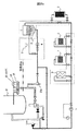
化学除染装置は、図3に示すように循環路内の除染液の温度を上昇させる加熱器(ヒータ)2を内蔵したサージタンク1,PLR配管22に除染液を供給するA循環ポンプ4,PLR配管22から除染液をサージタンク1に戻すB循環ポンプ5,溶解した酸化物を除去するカチオン樹脂塔7,除染液を浄化する混床樹脂塔8,還元除染液を分解する還元剤分解装置9,除染液を冷却する冷却器6を有する。配管(またはホース)30が、取合弁25aのボンネット部および取合弁25bのボンネット部に接続されている。配管30には上流側より、弁V5,B循環ポンプ5,弁V6,V7,V10,V13,V16,サージタンク1,A循環ポンプ4、および弁V1,V3が取り付けられている。弁V2を有する配管(またはホース)32が、弁V1の下流側で配管30に接続され、さらにサージタンク1に接続される。除染剤を投入する薬品投入口3が配管32に設けられている。
As shown in FIG. 3, the chemical decontamination apparatus is a
弁V8,V9を備えた配管(またはホース)34が、弁V7をバイパスするように配管30に接続される。冷却器6が弁V8と弁V9との間で配管34に設置される。弁V11,弁V12を備えた配管(またはホース)35が弁V10をバイパスするように配管30に接続される。カチオン樹脂塔7が弁V11と弁12との間で配管35に設置される。弁V14,弁V15を備えた配管(またはホース)36が、弁V13をバイパスするように配管30に接続される。混床樹脂塔8が弁V14と弁V15との間で配管36に設置される。弁V17,V18を備えた配管(またはホース)33が、弁V16をバイパスするように配管30に接続される。還元剤分解装置9が弁V17と弁V18との間で配管33に設置される。弁V4を備えたバイパス配管31が、弁V5の下流側で、弁V3の上流側で配管30に接続される。
A pipe (or hose) 34 including valves V8 and V9 is connected to the pipe 30 so as to bypass the valve V7. The
取合弁25aはA接合部27aを介してPLR配管22の垂直配管28に接続され、取合弁25bはB接合部27bを介してPLR配管22に接続されている。このため、配管30は、除染対象物であるPLR配管22に接続される。取合弁25a,25bはPLR配管と反対の方向に除染液が流れていかないように各々の弁ボデー内に閉止板26a,26bを設置している。
The
A循環ポンプ4およびB循環ポンプ5を駆動することによって、PLR配管22内の液体が、取合弁25a,A循環ポンプ4,サージタンク1,B循環ポンプ5および取合弁25bを経てPLR配管22に戻される。
By driving the
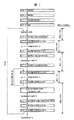
図1を用いて本実施例の化学除染方法を説明する。STEP1として弁V1,V4,V6,V7,V10,V13,V16を「開」とし、そのほかの弁を「閉」とする。このときのPLR配管22内の液位は図2(a)に示すようになっている。
The chemical decontamination method of this example will be described with reference to FIG. As
STEP2では、A循環ポンプ4とB循環ポンプ5を運転することにより、サージタンク1内の純水を、配管30、及びPLR配管22のバイパス配管31で形成される循環路に循環させる。その後、弁V3,V5を「開」、弁V4を「閉」として、サージタンク1内の純水をA循環ポンプ4によってPLR配管22に供給し、PLR配管22内の純水をB循環ポンプ5によってサージタンク1に戻す循環運転を行う。なお、前記ではPLR配管22のバイパス配管31に通水後、PLR配管22に通水し、バイパス配管31への通水を停止するとしているが、バイパス配管31に通水せずに、A循環ポンプ4およびB循環ポンプ5の運転開始から、PLR配管22に通水しても良い。
In
STEP3では、A循環ポンプ4から吐出される純水の流量をB循環ポンプ5から吐出される流量よりも多くし、サージタンク1からPLT配管22への供給量を多くして、図2(b)に示すようにPLR配管22内の純水の液位を垂直配管28の所定水位まで上昇させる。その液位が所定水位まで達したら、A循環ポンプ4とB循環ポンプ5のそれぞれから吐出される純水の流量を同じになるようにして、PLR配管22内の純水の液位を所定の水位に保持する。
In
PLR配管22内の液位が安定したら、サージタンク1内に内蔵している加熱器2の電源をONにして、所定の温度まで昇温する(STEP4)。純水が所定の温度に達したら、薬品投入口3から配管32内に酸化剤を投入し、配管30およびPLR配管22内の循環によって均一な酸化除染液を作る(STEP5)。
When the liquid level in the
STEP6では、A循環ポンプ4から吐出される酸化除染液の流量をB循環ポンプ5から吐出されるその流量よりも多くし、PLR配管22への酸化除染液供給量を多くし、図2(c)に示すようにリングヘッダ23およびライザー管24部の所定の液位までPLR配管22の液位を上昇させ、リングヘッダ23およびライザー管24に酸化除染液を供給する。酸化除染液の液位が所定の液位に達したら、液位が一定になるようにA循環ポンプ4とB循環ポンプ5の吐出流量を制御し、この状態を数時間保持することによって、PLR配管22,リングヘッダ23およびライザー管24部内のクロム酸化物の溶解を行う。
In
この時、リングヘッダ23およびライザー管24の酸化除染液の温度は、リングヘッダ23およびライザー管24部への除染液の液位上昇時間および保持時間内での放熱および配管への熱エネルギーの損失からPLR配管22内の循環路内で加熱された温度よりも低下する。除染液温度の低下により酸化除染効果は低下する。酸化除染効果が低下するのを抑制するため、リングヘッダ23に設置した電気ヒータ29の電源をONの状態で、酸化除染液位を上昇させる前からリングヘッダ23およびライザー管24部の予熱を行うとともに酸化除染液位がリングヘッダ23およびライザー管24部の所定の液位になった状態で除染液の再加熱を行い、PLR配管22循環路内の温度またはそれ以上の温度に保持することで、酸化除染効果(クロム酸化物の溶解を促進)を上昇させるものである。
At this time, the temperature of the oxidative decontamination liquid of the
ここで、図5に示すように電気ヒータ29はリングヘッダ23部の水平配管部に直接巻きつけられて、中継端子箱44を経由して制御盤45から電源が供給され加温される。加温効果を高めるために、電気ヒータ29を巻いたリングヘッダ23部に断熱材41を巻いて放熱を抑制した構造になっている。また、リングヘッダ23部に設置した監視用温度計42と制御用温度計43により規定温度に制御できる構成となっており、除染液温度を循環路内温度より高く制御することが可能であり、一定に制御することが可能な加温装置である。
Here, as shown in FIG. 5, the
酸化除染が終了したら、STEP7として、A循環ポンプ4の吐出流量をB循環ポンプ5の吐出流量よりも少なくし、PLR配管22内の酸化除染液の一部をサージタンク1に回収することによって、リングヘッダ23よりも低いPLR配管22の垂直配管28部の所定の水位に酸化除染液位を低下させる。
When the oxidative decontamination is completed, as
STEP8で、所定の液位に達したら、PLR配管22内の液位が一定に保持されるようにA循環ポンプ4とB循環ポンプ5の流量を制御した状態で、薬品投入口3から還元剤を投入し、酸化除染液を分解する。酸化除染液の分解終了後にSTEP9で弁V14,V15を「開」、V13を「閉」にし、配管36によりカチオン樹脂塔7に通水する。その後、薬品投入口3から還元剤を配管32内に追加投入し、配管30およびPLR配管22内の循環によって均一な還元除染液を作る。
When the predetermined liquid level is reached in
STEP10では、A循環ポンプ4から吐出される還元除染液の流量をB循環ポンプ5から吐出されるその流量よりも多くし、PLR配管22への還元除染液の供給量を多くし、サージタンク1内の還元除染液の一部をPLR配管22に供給することによって、リングヘッダ23およびライザー管24の所定水位までPLR配管22内の還元除染液位を上昇させる。これにより、水平配管集合管であるリングヘッダ23および垂直配管であるライザー管24に還元除染液を供給する。還元除染の液位が所定の水位に達したら、その液位が一定に保持されるように、A循環ポンプ4とB循環ポンプ5の各吐出流量を制御し、この状態を10数時間保持する。この期間において、PLR配管22,リングヘッダ23およびライザー管24内の鉄酸化物が溶解され、鉄イオンがカチオン樹脂塔7内のカチオン樹脂に吸着されて除去される。
In
この時も、リングヘッダ23およびライザー管24部への除染液の液位上昇時間、および保持時間内での放熱および配管の熱容量によりリングヘッダ23およびライザー管24の還元除染液の温度は、PLR配管22の循環路内で加熱された温度よりも低下する。除染液温度の低下により、還元除染効果が低下するのを抑制するため、リングヘッダ23部に設置した電気ヒータ29の電源をONの状態で除染液位の上昇開始前からリングヘッダ23およびライザー管24の予熱を行うとともに除染液の再加熱を行い、PLR配管22循環路内の温度またはそれ以上の温度に保持することで、還元除染効果(鉄酸化物の溶解促進効果)を上昇させるものである。この時には、電気ヒータ29の再加熱により循環路内の除染液温度よりも高く、一定に保たれることと併行して、リングヘッダ23部の温度と垂直配管であるライザー管24最上位部液位の除染液温度が放熱により低下することから十数度の温度差が生じる。よって、除染液の浮力による自然対流が強制対流になり垂直配管内を上下に循環することで、除染液温度の上昇による配管内表面の酸化皮膜の溶解速度が上がることと合わせて、皮膜の除去が可能となる相乗効果を発揮し、除染効果をさらに上昇することになる。
Also at this time, the temperature of the reductive decontamination liquid of the
図6に除染薬剤中における除染液温度と鉄酸化物の溶解速度の関係を示す。図6より、除染薬剤中における鉄酸化物の溶解速度は除染液温度に比例して溶解速度が上昇することが判っている。例えば、除染液温度が80℃の除染液と95℃の除染液では約2倍の溶解速度の差があり、配管等からの放熱により低下した除染液温度を循環路内の温度以上に上昇させることにより、除染効果を上昇させることになる。 FIG. 6 shows the relationship between the temperature of the decontamination solution in the decontamination drug and the dissolution rate of iron oxide. FIG. 6 shows that the dissolution rate of iron oxide in the decontamination drug increases in proportion to the temperature of the decontamination solution. For example, the decontamination liquid temperature of 80 ° C and the decontamination liquid of 95 ° C have a difference in dissolution rate of about twice, and the decontamination liquid temperature decreased due to heat radiation from the piping etc. By raising it above, the decontamination effect is raised.
また、垂直配管であるライザー管24部の鉄酸化物が除去されて水平配管であるリングヘッダ23部に堆積することがあり、リングヘッダ23の除染効果が見かけ上停滞しているようになることがある。この場合には、B循環ポンプ5の流量をA循環ポンプ4の流量より多くし、サージタンク1への除染液戻り量を多くし、リングヘッダ23およびライザー管24の液位から降下させ、液位がPLR配管22の所定の液位に達したら液位が一定に保持されるように、A循環ポンプ4とB循環ポンプ5の流量を制御した状態で保持し、再びA循環ポンプ4の流量をB循環ポンプ5の流量より多くし、PLR配管22への除染液供給量を多くし、リングヘッダ23およびライザー管24までの液位に上昇させ、還元除染液を供給する。所定の液位に達したら液位が一定に保持されるように、A循環ポンプ4とB循環ポンプ5の流量を制御する。
Further, the iron oxide in the
還元除染が終了したSTEP11では、A循環ポンプ4の吐出流量をB循環ポンプ5吐出流量より少なくし、PLR配管22内の還元除染液の一部をサージタンク1に回収する。これによって、リングヘッダ23より低いPLR配管22内の還元除染液の液位を低下させる。
In STEP 11 where the reduction decontamination is completed, the discharge flow rate of the
STEP12では、還元除染液の液位がPLR配管22の所定水位まで低下したとき、その液位を一定に保持するようにA循環ポンプ4とB循環ポンプ5の各吐出流量を制御する。その後、弁V17,V18を「開」、弁V16を「閉」とし、配管30内の還元除染液を還元剤分解装置9に供給して、還元除染液を除染剤分解装置9で分解する。還元除染液の分解が終了したとき、STEP13で弁V13を「開」、弁V14,V15を「閉」としてカチオン樹脂塔7をバイパスし、弁V8,V9,V11,V12を「開」、弁V7,V10を「閉」として冷却器6および混床樹脂塔8に除染液を通水して浄化する。
In STEP 12, when the liquid level of the reductive decontamination liquid drops to a predetermined water level in the
STEP14ではA循環ポンプ4の吐出流量をB循環ポンプ5の吐出流量よりも多くし、PLR配管22への液体の供給を多くし、サージタンク1内の浄化水の一部をPLR配管22内に供給する。これによって、PLR配管22内の液位をリングヘッダ23およびライザー管24部の所定の水位に達したら、その液位を一定に保持するように、A循環ポンプ4とB循環ポンプ5のそれぞれの吐出される流量を制御して、PLR配管22,リングヘッダ23およびライザー管24の内面に付着している還元除染剤を除去する。
In STEP 14, the discharge flow rate of the
STEP15では、A循環ポンプ4の吐出流量をB循環ポンプ5の吐出流量よりも少なくし、PLR配管22内の浄化水の一部をサージタンク1に回収する。これによってリングヘッダ23よりも低い液位まで低下させる。PLR配管22内の所定の水位で一定に保持されるように、A循環ポンプ4とB循環ポンプ5の各吐出流量を制御する。
In STEP 15, the discharge flow rate of the
STEP15とSTEP16の操作により、浄化水の液位上昇,下降を繰り返すことによって、リングヘッダ23およびライザー管24の内面に付着した還元除染剤を除去する。前記のような化学除染運転を1サイクルとして、PLR配管の汚染度合いに応じて2〜数サイクル程度繰り返し、化学除染を終了する。
The reduction decontaminant adhering to the inner surface of the
上記の図1のステップに合わせた状態について、液位状態を判りやすくフロー図により説明したものが図4である。図4では、垂直配管部の循環液位からリングヘッダ23およびライザー管24部の到達液位までに時間がかかり、配管の放熱により、除染液温度が低下することがわかる。
FIG. 4 illustrates the state in accordance with the above-described step of FIG. In FIG. 4, it can be seen that it takes time from the circulating liquid level in the vertical pipe section to the reached liquid level in the
最後に、実機プラントに適用した例を図7に示す。 Finally, an example applied to an actual plant is shown in FIG.
図7は、リングヘッダ23に加熱装置(電気ヒータ29)を設置して、循環路内の除染液温度以上にリングヘッダ23の温度を制御して実施した結果である。電気ヒータ29を設置してなくて再加熱ができなかった先行例と比較して、電気ヒータ29を設置して再加熱を実施結果では約2倍以上の除染効果の違いが生じている結果となった。よって、電気ヒータ29を設置することは、リングヘッダ23部の化学除染に有効であることといえる。
FIG. 7 shows a result obtained by installing a heating device (electric heater 29) in the
実施例1は、リングヘッダ23部に電気ヒータ29を螺旋状に直接巻き、その上に断熱材41を設置して、リングヘッダ23部および酸化,還元除染液を加熱して、PLR配管22循環路内の除染液温度以上に加熱するものであった。その場合、電気ヒータ29を螺旋状に直接設置することおよび断熱材41を化学除染前に設置することから準備作業における作業員の被ばく線量が高くなった。
In the first embodiment, the
実施例2としての加熱装置を図8に示す。図8は、前記化学除染方法と同様の方法で実施するもので、リングヘッダ23部の加熱装置として、電気ヒータ29を内蔵したパッケージ型保温材をジャケット方式にし、準備作業の合理化および作業員の被ばく低減に寄与することを目的にした装置である。
A heating apparatus as Example 2 is shown in FIG. FIG. 8 is carried out by the same method as the above chemical decontamination method. As a heating device for the
1 サージタンク
2 加熱器
3 薬品投入口
4 A循環ポンプ
5 B循環ポンプ
6 冷却器
7 カチオン樹脂塔
8 混床樹脂塔
9 還元剤分解装置
21 原子炉圧力容器
22 PLR配管
23 リングヘッダ
24 ライザー管
25a,25b 取合弁
26a,26b 閉止板
27 接合部
28 垂直配管
29 電気ヒータ
DESCRIPTION OF
Claims (6)
Priority Applications (1)
| Application Number | Priority Date | Filing Date | Title |
|---|---|---|---|
| JP2007279765A JP4901691B2 (en) | 2007-10-29 | 2007-10-29 | Chemical decontamination method |
Applications Claiming Priority (1)
| Application Number | Priority Date | Filing Date | Title |
|---|---|---|---|
| JP2007279765A JP4901691B2 (en) | 2007-10-29 | 2007-10-29 | Chemical decontamination method |
Publications (2)
| Publication Number | Publication Date |
|---|---|
| JP2009109253A true JP2009109253A (en) | 2009-05-21 |
| JP4901691B2 JP4901691B2 (en) | 2012-03-21 |
Family
ID=40777892
Family Applications (1)
| Application Number | Title | Priority Date | Filing Date |
|---|---|---|---|
| JP2007279765A Expired - Fee Related JP4901691B2 (en) | 2007-10-29 | 2007-10-29 | Chemical decontamination method |
Country Status (1)
| Country | Link |
|---|---|
| JP (1) | JP4901691B2 (en) |
Cited By (2)
| Publication number | Priority date | Publication date | Assignee | Title |
|---|---|---|---|---|
| JP2012013555A (en) * | 2010-07-01 | 2012-01-19 | Hitachi-Ge Nuclear Energy Ltd | Method for chemical decontamination of nuclear power plant |
| JP2013228402A (en) * | 2013-06-24 | 2013-11-07 | Toshiba Corp | Decontamination device of facility in nuclear power plant |
Families Citing this family (1)
| Publication number | Priority date | Publication date | Assignee | Title |
|---|---|---|---|---|
| WO2023063493A1 (en) * | 2021-10-15 | 2023-04-20 | 스마트파워 주식회사 | System and method for predicting total radioactivity leaked by coolant leakage accident during chemical decontamination process |
Citations (9)
| Publication number | Priority date | Publication date | Assignee | Title |
|---|---|---|---|---|
| JPH01320497A (en) * | 1988-06-22 | 1989-12-26 | Jgc Corp | Chemical decontamination method |
| JPH03105064U (en) * | 1989-11-14 | 1991-10-31 | ||
| JPH07299429A (en) * | 1994-05-11 | 1995-11-14 | T H I Syst Kk | Tubular body washing device |
| JPH10180207A (en) * | 1996-08-08 | 1998-07-07 | Nippon A P I:Kk | Surface purifying method, its device, surface purified material method for applying same, clip member, and semiconductor manufacturing device |
| JP2003090897A (en) * | 2001-09-18 | 2003-03-28 | Toshiba Corp | Chemical decontamination method and device for carbon steel member |
| JP2004294393A (en) * | 2003-03-28 | 2004-10-21 | Toshiba Corp | Chemical decontamination method |
| JP2005069898A (en) * | 2003-08-25 | 2005-03-17 | Toshiba Corp | Decontamination device for facility in nuclear power plant and its decontamination method |
| JP2005164344A (en) * | 2003-12-02 | 2005-06-23 | Hitachi Ltd | Chemical decontamination method |
| WO2007062743A2 (en) * | 2005-11-29 | 2007-06-07 | Areva Np Gmbh | Method for the decontamination of an oxide layer-containing surface of a component or a system of a nuclear facility |
-
2007
- 2007-10-29 JP JP2007279765A patent/JP4901691B2/en not_active Expired - Fee Related
Patent Citations (10)
| Publication number | Priority date | Publication date | Assignee | Title |
|---|---|---|---|---|
| JPH01320497A (en) * | 1988-06-22 | 1989-12-26 | Jgc Corp | Chemical decontamination method |
| JPH03105064U (en) * | 1989-11-14 | 1991-10-31 | ||
| JPH07299429A (en) * | 1994-05-11 | 1995-11-14 | T H I Syst Kk | Tubular body washing device |
| JPH10180207A (en) * | 1996-08-08 | 1998-07-07 | Nippon A P I:Kk | Surface purifying method, its device, surface purified material method for applying same, clip member, and semiconductor manufacturing device |
| JP2003090897A (en) * | 2001-09-18 | 2003-03-28 | Toshiba Corp | Chemical decontamination method and device for carbon steel member |
| JP2004294393A (en) * | 2003-03-28 | 2004-10-21 | Toshiba Corp | Chemical decontamination method |
| JP2005069898A (en) * | 2003-08-25 | 2005-03-17 | Toshiba Corp | Decontamination device for facility in nuclear power plant and its decontamination method |
| JP2005164344A (en) * | 2003-12-02 | 2005-06-23 | Hitachi Ltd | Chemical decontamination method |
| WO2007062743A2 (en) * | 2005-11-29 | 2007-06-07 | Areva Np Gmbh | Method for the decontamination of an oxide layer-containing surface of a component or a system of a nuclear facility |
| JP2009517638A (en) * | 2005-11-29 | 2009-04-30 | アレヴァ エンペー ゲゼルシャフト ミット ベシュレンクテル ハフツング | Method for decontaminating a surface of a nuclear facility part or system containing an oxide layer |
Cited By (2)
| Publication number | Priority date | Publication date | Assignee | Title |
|---|---|---|---|---|
| JP2012013555A (en) * | 2010-07-01 | 2012-01-19 | Hitachi-Ge Nuclear Energy Ltd | Method for chemical decontamination of nuclear power plant |
| JP2013228402A (en) * | 2013-06-24 | 2013-11-07 | Toshiba Corp | Decontamination device of facility in nuclear power plant |
Also Published As
| Publication number | Publication date |
|---|---|
| JP4901691B2 (en) | 2012-03-21 |
Similar Documents
| Publication | Publication Date | Title |
|---|---|---|
| JP5091727B2 (en) | Chemical decontamination method | |
| JP2010021215A (en) | Cleaning system and method for circulating cleaning fluid | |
| JP4901691B2 (en) | Chemical decontamination method | |
| JP2012247322A (en) | Method for forming platinum film on plant component | |
| JP2017223524A (en) | Chemical decontamination system and chemical decontamination method of reactor pressure vessel | |
| JPS6323519B2 (en) | ||
| JP6501482B2 (en) | Decontamination treatment system and decomposition method of decontamination wastewater | |
| KR920002562B1 (en) | Flow control method for radioactive decontamination of nuclear steam generator | |
| US8821973B2 (en) | Method of forming Fe3-xCrxO4 (O<X≦0.1) film on structural member in a plant | |
| JP4927210B2 (en) | Methods for chemical dissolution of corrosion products | |
| JP6132382B2 (en) | Processing method of decontamination solution | |
| JP4317737B2 (en) | Chemical decontamination method | |
| JP4167920B2 (en) | Chemical decontamination method | |
| JP2010127788A (en) | Ferrite film formation method on surface of plant component, ferrite film formation device, and quartz oscillator electrode device | |
| JP6088173B2 (en) | Method for suppressing radionuclide adhesion to components of nuclear power plant | |
| JP4945487B2 (en) | Method and apparatus for forming ferrite film on carbon steel member | |
| KR102356764B1 (en) | Wastewater treatment method due to decontamination of metal surfaces, wastewater treatment equipment and uses of wastewater treatment equipment | |
| TWI814091B (en) | Chemical decontamination method | |
| TWI825540B (en) | Chemical decontamination methods and chemical decontamination devices | |
| JP5749666B2 (en) | Decontamination apparatus and decontamination method | |
| JP5318039B2 (en) | Chemical decontamination method for nuclear power plant | |
| JP6359313B2 (en) | Waste liquid treatment system and waste liquid treatment method | |
| JPS59143996A (en) | Method of operating early oxydation of atomic power plant | |
| JP5912886B2 (en) | Chemical decontamination method | |
| JP5763520B2 (en) | Cleaning method for nuclear plant components |
Legal Events
| Date | Code | Title | Description |
|---|---|---|---|
| A621 | Written request for application examination |
Free format text: JAPANESE INTERMEDIATE CODE: A621 Effective date: 20100127 |
|
| A521 | Request for written amendment filed |
Free format text: JAPANESE INTERMEDIATE CODE: A523 Effective date: 20100127 |
|
| A977 | Report on retrieval |
Free format text: JAPANESE INTERMEDIATE CODE: A971007 Effective date: 20110728 |
|
| A131 | Notification of reasons for refusal |
Free format text: JAPANESE INTERMEDIATE CODE: A131 Effective date: 20110802 |
|
| A521 | Request for written amendment filed |
Free format text: JAPANESE INTERMEDIATE CODE: A523 Effective date: 20111003 |
|
| TRDD | Decision of grant or rejection written | ||
| A01 | Written decision to grant a patent or to grant a registration (utility model) |
Free format text: JAPANESE INTERMEDIATE CODE: A01 Effective date: 20111129 |
|
| A01 | Written decision to grant a patent or to grant a registration (utility model) |
Free format text: JAPANESE INTERMEDIATE CODE: A01 |
|
| A61 | First payment of annual fees (during grant procedure) |
Free format text: JAPANESE INTERMEDIATE CODE: A61 Effective date: 20111227 |
|
| R150 | Certificate of patent or registration of utility model |
Ref document number: 4901691 Country of ref document: JP Free format text: JAPANESE INTERMEDIATE CODE: R150 Free format text: JAPANESE INTERMEDIATE CODE: R150 |
|
| FPAY | Renewal fee payment (event date is renewal date of database) |
Free format text: PAYMENT UNTIL: 20150113 Year of fee payment: 3 |
|
| LAPS | Cancellation because of no payment of annual fees |