JP2009107037A - Spindle structure of lathe - Google Patents
Spindle structure of lathe Download PDFInfo
- Publication number
- JP2009107037A JP2009107037A JP2007279138A JP2007279138A JP2009107037A JP 2009107037 A JP2009107037 A JP 2009107037A JP 2007279138 A JP2007279138 A JP 2007279138A JP 2007279138 A JP2007279138 A JP 2007279138A JP 2009107037 A JP2009107037 A JP 2009107037A
- Authority
- JP
- Japan
- Prior art keywords
- main shaft
- lathe
- hole
- cylinder
- piston
- Prior art date
- Legal status (The legal status is an assumption and is not a legal conclusion. Google has not performed a legal analysis and makes no representation as to the accuracy of the status listed.)
- Pending
Links
Images


Abstract
Description
本発明は、ヤトイユニットを備えた旋盤の主軸構造に関する。 The present invention relates to a main spindle structure of a lathe provided with a Yatoi unit.
図5は、ヤトイユニットを装着した従来の旋盤の主軸構造を示す断面図で、図6は、主軸先端部の拡大図である。
図5、図6に示すように、NC旋盤の主軸1は、主軸台の内部に複数の軸受2を介して回転自在に保持されている。主軸1の内部の軸中心には、ワーク3をヤトイ4でクランプするための栓5をその先端部に着脱自在に保持するためのワーククランプ用ドローバー6と、このワーククランプ用ドローバー6の後端にそのシリンダピストン8を連結されて軸方向に進退せしめるワーククランプ用シリンダ7とを備えている。さらに、前記主軸1の内部には、前記のワーククランプ用ドローバー6を外囲してこれと同心の管状に設けられ、ヤトイ4をその先端部に着脱自在に保持するためのチャッククランプ用ドローバー9と、このチャッククランプ用ドローバー9の後端にそのシリンダピストン11を連結されて軸方向に進退せしめるチャッククランプ用シリンダ10とを備えている。
FIG. 5 is a cross-sectional view showing a spindle structure of a conventional lathe equipped with a Yatoi unit, and FIG. 6 is an enlarged view of the spindle tip.
As shown in FIGS. 5 and 6, the
したがって、アンクランプにするには、ワーククランプ用シリンダ7のシリンダピストン8を作動し、ワーククランプ用ドローバー6を図面の右方向へ前進させる。そうすると、栓5が図面の右方向へ前進し、開きヤトイ4は元の位置にとどまったままであるので、開きヤトイ4が弾性により縮径する。この状態で、ワーク3を図面の右方向へ抜き取る。この状態で、新たなワーク3を図面の右側から縮径した開きヤトイ4に外嵌する。シリンダ7のシリンダピストン8を作動し、ワーククランプ用ドローバー6を図面の左方向へ後退させる。そうすると、栓5が図面の左方向へ後退し、開きヤトイ4は元の位置にとどまったままであるので、開きヤトイ4が栓5により拡径される。その結果、開きヤトイ4の大径円筒部4の外周がワーク3の内周面に圧接され、ワーク3が開きヤトイ4にクランプされ、主軸1の前端部に、開きヤトイ4を自動的着脱自在に保持するように構成されている。
Accordingly, in order to unclamp, the cylinder piston 8 of the work clamping cylinder 7 is operated, and the work clamping draw bar 6 is advanced in the right direction in the drawing. Then, the plug 5 moves forward in the right direction of the drawing, and the
しかしながら、従来のヤトイユニットは、円筒形のワークを主軸先端部に着脱するためには、主軸1の貫通穴にドローバー6を通し、そのドローバー6を主軸内で支持し、常にドローバー6で軸方向に常に引張らなければならなかった。
そのため、高速回転時にドローバー6が半径方向に撓んで振動を発生させ、ワークにビビリマークを生じ、加工精度に影響を与え、品質の向上が図れないという問題があった。
そこで、本発明は、これらの問題点を解決するため、円筒形ワークの加工精度が高く、かつ、主軸の高速回転を可能として生産性の向上を図るようにしたヤトイユニットを提供することを課題する。
However, in the conventional Yatoi unit, in order to attach and detach a cylindrical workpiece to and from the tip of the main shaft, the draw bar 6 is passed through the through hole of the
For this reason, there is a problem that the draw bar 6 is bent in the radial direction during high-speed rotation to generate vibrations, causing chatter marks on the workpiece, affecting the machining accuracy and not improving the quality.
SUMMARY OF THE INVENTION In order to solve these problems, it is an object of the present invention to provide a Yatoi unit that has a high machining accuracy for a cylindrical workpiece and that is capable of high-speed rotation of a spindle to improve productivity. To do.
請求項1に係る発明の旋盤の主軸構造であって、主軸の先端部に装着され、円筒形のワークWを内側から把持するヤトイユニットと、前記主軸の後端部から先端部まで貫通して穿設された中空穴と、この中空穴に前記後端部から圧縮空気を供給する流体供給装置と、を備えた旋盤の主軸構造であって、
前記ヤトイユニットは、前記主軸の先端部に固定された円盤状のフランジと、前記フランジに固定された筒状のシリンダと、前記シリンダの先端部に固定され、中央に貫通穴を有する基台と、前記シリンダの内周面に摺動自在に支持され、前記基台の貫通穴に挿通させて突出させたボス部を有するピストンと、前記基台と前記ピストンに挟持され、前記ピストンを前記主軸側に付勢するスプリングと、前記基台に固定され、ワークの内周面を把持するために外周面に設けられた把持部と、先端側が拡径されたテーパ穴と、前記ボス部に固定され、前記テーパ穴に係合して前記把持部を拡径させるテーパガイドと、を備えたことを特徴とする。
なお、流体供給装置に用いられ最良の形態は、流体として空気、作動油を使用でき、空圧、油圧を利用して、ヤトイユニットを作動するものである。
A main spindle structure of a lathe according to the first aspect of the present invention, wherein a Yatoi unit is attached to the front end of the main spindle and grips a cylindrical workpiece W from the inside, and penetrates from the rear end to the front end of the main spindle. A lathe spindle structure comprising a drilled hollow hole and a fluid supply device for supplying compressed air from the rear end to the hollow hole,
The Yatoi unit includes a disk-shaped flange fixed to the tip of the main shaft, a cylindrical cylinder fixed to the flange, a base fixed to the tip of the cylinder and having a through hole in the center; A piston having a boss portion that is slidably supported on an inner peripheral surface of the cylinder and is protruded by being inserted through a through hole of the base, and is sandwiched between the base and the piston, and the piston is attached to the main shaft Fixed to the boss, a spring that is biased to the side, a gripping portion that is fixed to the base and is provided on the outer peripheral surface to grip the inner peripheral surface of the workpiece, a tapered hole whose tip end is enlarged in diameter, and And a taper guide that engages with the taper hole and expands the diameter of the grip portion.
It should be noted that the best mode used for the fluid supply apparatus can use air or hydraulic oil as the fluid, and operates the Yatoi unit using pneumatic pressure or hydraulic pressure.
請求項2に係る発明は、請求項1記載の旋盤の主軸構造であって、前記流体供給装置は、前記主軸の後端開口部に接離するように圧縮空気を移送する管を配設し、前記管の先端に設けられたノズルを設け、前記ノズルを進退自在に支持する駆動手段と、を備えたことを特徴とする。
The invention according to
本発明の旋盤の主軸構造によれば、従来のように、主軸の内部にドローバーを装着せずに、空圧でヤトイユニットを操作できるので、主軸の高速回転に伴う振動を抑えながら、加工精度の向上および生産性の向上を図ることができる。
また、本発明のヤトイユニットは、円筒形ワークを確実にクランプし、円筒形ワークの全周面の加工を行うことができる。
また、ヤトイをクランプ、アンクランプとも空圧または、油圧シリンダで動作させる場合に比べて、本発明のように片側にスプリングを用いて、クランプするように構成したので、何らかのトラブル例えば、停電により、旋盤に電気が供給されなくなり機械が停止した場合であっても、ワークのクランプは、継続して維持することができる。
According to the main spindle structure of the lathe of the present invention, the Yatoi unit can be operated by pneumatic pressure without attaching a draw bar inside the main spindle, as in the past, so that machining accuracy can be reduced while suppressing vibration associated with high-speed rotation of the main spindle. And productivity can be improved.
Further, the Yatoi unit of the present invention can securely clamp the cylindrical workpiece and process the entire circumferential surface of the cylindrical workpiece.
Also, compared to the case where the Yatoi is clamped and unclamped by pneumatic or hydraulic cylinders, it is configured to clamp using a spring on one side as in the present invention. Even when electricity is not supplied to the lathe and the machine is stopped, the workpiece clamping can be continuously maintained.
以下、本発明の実施の形態を、図面を参照しながら詳細に説明する。
旋盤の主軸全体構成
図1は本発明に係るヤトイユニットを装着した旋盤の主軸の縦断面を示す。
旋盤の主軸台10は、図1に示すように、旋盤図示省略のベッド11上に固定され、主軸14は、長尺の中空部材で軸線方向に中空穴14cが貫通し、主軸台10の本体10aに設けたハウジング10c、10dに軸受12を介して回転自在に水平に支持され、右端の軸受12は、軸受押え18で支持している。主軸14の外周には、主軸14の外周側に装着したロータ15aと、本体10aに装着した冷却用のスリーブ10bの内周面に嵌合したステータ15bとによって構成されたビルトインモータ15により、直接回転駆動することができる。さらに、主軸14の後端部には、主軸14にアダプタ14aを螺合している。
Hereinafter, embodiments of the present invention will be described in detail with reference to the drawings.
FIG. 1 shows a longitudinal section of a main spindle of a lathe equipped with a Yatoi unit according to the present invention.
As shown in FIG. 1, the lathe headstock 10 is fixed on a bed 11 (not shown), and the
(ヤトイユニット)
ヤトイユニットは、旋盤の主軸14と同一軸線上に配置した、ヤトイを圧力流体でワークをアンクランプし、ワークをスプリング力でクランプするシリンダ機構Mと、旋盤の主軸内を通過してシリンダ機構M側に圧力流体を供給する流体供給手段Pと、ワークWをクランプするヤトイ機構Nから構成される。
(Yatoi unit)
The Yatoi unit is arranged on the same axis as the
なお、このヤトイユニットは、内側からワークWをクランプするため、一般的にAL製の円筒形部材の全周面を加工するような軽切削用または軽研削加工用に使用される。
また、本実施態様においては、ヤトイユニット20の流体供給装置Pに用いられる流体として空気を用いた。
In addition, since this Yatoi unit clamps the workpiece | work W from an inner side, generally it is used for the light cutting or light grinding which processes the whole peripheral surface of the cylindrical member made from AL.
In the present embodiment, air is used as the fluid used in the fluid supply device P of the Yato unit 20.
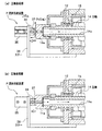
ヤトイユニット20を構成する部品、機構について、図2(a)、(b)に示す分解組立図および、動作状態を示す断面図、図3、図4を参照して、詳細に説明を行う。
(シリンダ機構)
シリンダ機構Mは、主軸14端面にボルト21fで固定されたフランジ21と、シリンダ22と、ボス部25aをボルト25lで固定したピストン25およびシリンダ22と締結した基台29から構成される。
すなわち、フランジ21は、シリンダ22の一端を形成し、円盤状に形成され、ボルト21fを介して主軸14に固定されている。主軸14の側端面には、フランジ21と主軸14との芯合わせをするための凹部図示省略が形成されており、前記凹部図示省略と主軸14の端面の外周部が嵌合され、ボルト21fによって固定されている。
The parts and mechanisms constituting the Yatoi unit 20 will be described in detail with reference to exploded views shown in FIGS. 2 (a) and 2 (b), sectional views showing operating states, and FIGS. 3 and 4. FIG.
(Cylinder mechanism)
The cylinder mechanism M includes a
That is, the
また、シリンダ22は、円筒状に形成され、基台29にボルト17によって固定されている。ピストン25には、図2(a)、(b)に示すように、スプリング26を位置決めする止り穴25jが8箇所、基台29の端面には、止り穴29jが8箇所、それぞれ対向して設けられ、スプリング26は、止り穴25j、止り穴29jに上下端を挿入して、基台29とピストン25の間で狭持され、ボルト16で締結され固定されている。
また、ピストン25の外周にOリング溝25cを成形し、Oリング溝25cにOリング25bを装着し、主軸14にも同様にOリング溝図示省略を成形し、Oリング14bを装着し、圧縮空気の機密性を保持することができる。
The
In addition, an O-
なお、シリンダ22の内周面22aは、ピストン25のOリング25bが摺動可能とするため、滑らかに仕上げられている。また、このシリンダ22は、切削加工により、前記したフランジ21と一体化した部品として構成してもよい。
また、基台29は、シリンダ22を介して、フランジ21の端面にボルト16によって固定されている。
したがって、圧縮空気が停止された時点ワークWのクランプ時点で、ピストン25および中空穴14c側の圧縮空気は、大気に開放される。このとき、ピストン25は、スプリング26のスプリング力により、主軸14と反対の先端部方向に移動することができる。
The inner
The
Therefore, when the compressed air is stopped, when the workpiece W is clamped, the compressed air on the
(流体供給装置)
流体供給装置Pは、図1に示すように、主軸14後端部より主軸14の中空穴14cを通過して、シリンダ22とピストン25により形成した空間に圧縮空気を供給し、スプリング力より強い加圧力でピストン25を移動させる装置である。
主軸14の後部には、本体10aに取付けステー38を固定し、その先端に、駆動手段としてのエアシリンダ35を支持し、そのピストン35aの先端には、クッション37付ノズル34を設けている。クッション37付ノズル34は、エアシリンダ35の作動により、主軸14後端面のアダプタ14a部と接離自在に移動することができる。
クッション37の材料は、耐油性のゴムなどの弾性力のある素材が好ましい。
(Fluid supply device)
As shown in FIG. 1, the fluid supply device P passes through the
An
The material of the
(ヤトイ機構)
基台29は、円盤状に形成され、シリンダ22の他端部を形成している。基台29の中央には、ピストン25のボス部25aが摺動可能な貫通穴29aが設けられ、さらに、ヤトイ30との芯合わせをするための凹部29cが形成されており、この凹部29cとヤトイ30のフランジ30fが嵌合され、ボルト18によって固定されている。
ヤトイ30は、ワークWの内周面を直接押圧して、ワークWを保持するチャックの一種であり、開ヤトイとも言う。ヤトイ30の後端部にはフランジ30fが形成されており、このフランジ30fが基台29の端面に設けられた凹部29cに嵌合されて位置を決め、ボルト18によって固定されている。ヤトイ30の把持部30dは、先端部に設けられた把持部30dまでの間は、外径を細くした逃げが施され、変形し易くしている。
さらに、中心部にはピストン25のボス部25aを嵌合した穴部30gが設けられ、先端部にはテーパ穴30cが形成されている。
テーパガイド33は、図2に示すように、ヤトイ30のスリット溝30eを形成した把持部30dに弾性変形を生じさせて、把持部30dを拡径する機能を有する。なお、ヤトイ30の把持部30dの外側に、弾性体としてゴム製のリングを装着して、摩擦力を向上させるようにしてもよい。
(Yatoi mechanism)
The
The
Further, a
As shown in FIG. 2, the
テーパガイド33のテーパ角を微調整できるようにテーパ角微調整機構Cが設けられている。この機構Cは、テーパガイド33の中心に穴部30fを設け、その奥に、メねじ33eをねじ切りし、このねじにさら小ねじ33fが螺合している。さらに、ボス部25aにメねじ25fを形成し、メねじ25fにテーパガイド33のねじ33gが螺合している。
したがって、さら小ねじ33dをドライバー工具で回転すると、このさら小ねじ33fの頭部のテーパ面がテーパ穴30cに接触し、テーパガイド33のテーパ部を調整して、把持部30dの拡径を調整できるようになっている。
A taper angle fine adjustment mechanism C is provided so that the taper angle of the
Therefore, when the
(ヤトイユニットの動作)
次に、ヤトイユニット20による円筒形状のワークWの着脱動作について、以下に詳細に述べる。
ワークWの主軸14への装着は、図3(a)に示すように、図1に示す方向切換弁39を切換えて、図3(b)に示すように、クッション37付ノズル34を主軸14端に設けたアダプタ14aの端面に密着し、主軸14の後端側から主軸14の中空穴14c内に圧縮空気を供給し、この圧縮空気の圧力により、スプリング26のスプリング力に抗してピストン25を前進させる。すると、ピストン25が右行前進し、ピストン25の移動に追従して、テーパ穴30cとテーパガイド33の係合が解かれ、把持部30dが弾性力により縮径し、ワークWを装着可能な状態にする。
(Operation of Yatoi unit)
Next, the attaching / detaching operation of the cylindrical workpiece W by the Yatoi unit 20 will be described in detail below.
As shown in FIG. 3A, the work W is mounted on the
ワークWの主軸14への装着は、ワークWを把持部30dへ装着後、図3(b)に示すように、方向切換弁39を切替えて、ノズル34をアダプタ14a端から離間し、空気の供給を遮断し、主軸14内の中空穴14c内の圧縮空気を大気に開放する。その結果、スプリング26のスプリング力により、ピストン25が左行する。ピストン25の移動に追従して、テーパ穴30cとテーパガイド33がテーパ面で係合し、把持部30dが半径方向に拡径し、ワークWを内側からクランプする。
したがって、ワークWは、ヤトイ30の先端の把持部30dでクランプがなされる。ワークWの外周面の加工が終わると、ワークWの取り外し作業を行う。
ワークWの加工後、取外しは、図1に示すように状態で、方向切換弁39を切替えて、図3(b)に示すように、ノズル34に設けたクッション37を介して、主軸14端に密着し、主軸14の中空穴14c内に圧縮空気を供給し、この圧縮空気の圧力により、ピストン25をスプリング26に抗して前進させる。そして、ピストン25が右行すると、ピストン25の移動に追従して、テーパ穴30cとテーパガイド33の係合が解かれ、スプリング26を介して、テーパガイド33が右方向に移動して、把持部30dが弾性力により縮径し、ワークWはアンランプされる。この状態で、ワークWを図面右方向へ抜き取り、すべての作業を完了する。
As shown in FIG. 3 (b), the work W is mounted on the
Accordingly, the workpiece W is clamped by the
After the workpiece W is processed, the removal is performed in the state shown in FIG. 1 by switching the
以上、本発明の一実施の形態の構成とその作用について説明したが、本発明はこの実施の形態に限られるものではない。
例えば、前記実施の形態においては、ヤトイを閉じ、ワークWをアンランプにする圧縮空気供給手段は、空圧または油圧を付与する空圧または油圧回路を設けるようにしてもよい。
また、上記実施態様においては、圧縮空気は、主軸14後部より主軸14の中空穴14c内に圧縮空気を供給したが、また、別の態様として、空気供給手段Pは、シリンダ部に側面から、空圧または油圧を付勢する空圧回路または油圧回路を接続することもできる。
さらに、シリンダ機構Mに設けたピストン25に対して、主軸14の前部側面から中空穴を通過して、主軸14後部より圧縮空気を供給し、その圧力により作動するようにしてもよい。
上述したヤトイは、これ以外に、閉めヤトイやサンドイッチクランプ方式のチャック等他のチャック類にも適用可能である。閉めヤトイとは、通常コレットチャックと呼ばれ、ドリル、リーマ等の工具を取り付けるためのチャックである。
The configuration and operation of one embodiment of the present invention have been described above, but the present invention is not limited to this embodiment.
For example, in the above embodiment, the compressed air supply means that closes the yatoy and unruns the workpiece W may be provided with an air pressure or hydraulic circuit that applies air pressure or oil pressure.
Moreover, in the said embodiment, although compressed air supplied compressed air in the
Furthermore, the
In addition to this, the above-described yatoy can be applied to other chucks such as a closing yatoy or a sandwich clamp type chuck. The closing yatoy is usually called a collet chuck, and is a chuck for attaching a tool such as a drill or a reamer.
M シリンダ機構
N ヤトイ機構
P 流体供給手段
10 主軸台
10a 本体
14 主軸
14c 中空穴
15 ビルトインモータ
20 ヤトイユニット
21 フランジ
22 シリンダ
22a 内周面
25 ピストン
25a ボス部
26 スプリング
29 基台
30 ヤトイ
30c テーパ穴
30d 把持部
30f フランジ
33 テーパガイド
35 エアシリンダ駆動手段
M Cylinder mechanism N Yatoi mechanism P Fluid supply means 10 Main shaft base
Claims (2)
前記ヤトイユニットは、
前記主軸の先端部に固定された円盤状のフランジと、
前記フランジに固定された筒状のシリンダと、
前記シリンダの先端部に固定され、中央に貫通穴を有する基台と、
前記シリンダの内周面に摺動自在に支持され、前記基台の貫通穴に挿通させて突出させたボス部を有するピストンと、
前記基台と前記ピストンに挟持され、前記ピストンを前記主軸側に付勢するスプリングと、
前記基台に固定され、ワークの内周面を把持するために外周面に設けられた把持部と、先端側が拡径されたテーパ穴とを有するヤトイと、
前記ボス部に固定され、前記テーパ穴に係合して前記把持部を拡径させるテーパガイドと、
を備えたことを特徴とする旋盤の主軸構造。 A Yatoi unit that is attached to the front end of the main shaft and grips the cylindrical workpiece W from the inside, a hollow hole that penetrates from the rear end portion to the front end portion of the main shaft, and the rear end in the hollow hole A lathe main spindle structure comprising a fluid supply device for supplying compressed air from a section,
The Yatoi unit is
A disc-shaped flange fixed to the tip of the spindle;
A cylindrical cylinder fixed to the flange;
A base fixed to the tip of the cylinder and having a through hole in the center;
A piston having a boss portion that is slidably supported on the inner peripheral surface of the cylinder and is protruded by being inserted into a through hole of the base;
A spring sandwiched between the base and the piston and biasing the piston toward the main shaft;
A yatoy fixed to the base and having a gripping portion provided on the outer peripheral surface for gripping the inner peripheral surface of the workpiece, and a tapered hole having an enlarged diameter on the tip side;
A taper guide fixed to the boss portion and engaged with the taper hole to expand the grip portion;
A lathe spindle structure characterized by comprising
前記主軸の後端開口部に接離するように、圧縮空気を移送する管を配設し、前記管の先端に設けられたノズルと、
前記ノズルを進退自在に支持する駆動手段と、
を備えたことを特徴とする請求項1に記載の旋盤の主軸構造。 The fluid supply device includes:
A pipe for transferring compressed air so as to be in contact with and away from the rear end opening of the main shaft, and a nozzle provided at the tip of the pipe;
Driving means for supporting the nozzle so as to be movable forward and backward;
The main spindle structure of a lathe according to claim 1, comprising:
Priority Applications (1)
| Application Number | Priority Date | Filing Date | Title |
|---|---|---|---|
| JP2007279138A JP2009107037A (en) | 2007-10-26 | 2007-10-26 | Spindle structure of lathe |
Applications Claiming Priority (1)
| Application Number | Priority Date | Filing Date | Title |
|---|---|---|---|
| JP2007279138A JP2009107037A (en) | 2007-10-26 | 2007-10-26 | Spindle structure of lathe |
Publications (1)
| Publication Number | Publication Date |
|---|---|
| JP2009107037A true JP2009107037A (en) | 2009-05-21 |
Family
ID=40776121
Family Applications (1)
| Application Number | Title | Priority Date | Filing Date |
|---|---|---|---|
| JP2007279138A Pending JP2009107037A (en) | 2007-10-26 | 2007-10-26 | Spindle structure of lathe |
Country Status (1)
| Country | Link |
|---|---|
| JP (1) | JP2009107037A (en) |
Cited By (3)
| Publication number | Priority date | Publication date | Assignee | Title |
|---|---|---|---|---|
| JP2012130978A (en) * | 2010-12-20 | 2012-07-12 | Showa Denko Kk | Lathe chuck |
| JP2016016508A (en) * | 2014-07-08 | 2016-02-01 | ロェーム ゲーエムベーハー | Fastening chuck having quick exchange function and fastening mechanism part |
| CN107838809A (en) * | 2017-11-09 | 2018-03-27 | 科森科技东台有限公司 | Auxiliary clamp for mobile phone component polishing |
Citations (3)
| Publication number | Priority date | Publication date | Assignee | Title |
|---|---|---|---|---|
| JPS5228187A (en) * | 1975-08-29 | 1977-03-02 | Tokyo Kinguran Kk | Power source circuit for discharging lamps |
| JPS5817906A (en) * | 1981-07-24 | 1983-02-02 | 日本道路株式会社 | Thin layer laying and leveling machine for mastic mixture |
| JPH10138069A (en) * | 1996-11-01 | 1998-05-26 | Amada Co Ltd | Work setting method on pallet, its pallet, and pallet support base |
-
2007
- 2007-10-26 JP JP2007279138A patent/JP2009107037A/en active Pending
Patent Citations (3)
| Publication number | Priority date | Publication date | Assignee | Title |
|---|---|---|---|---|
| JPS5228187A (en) * | 1975-08-29 | 1977-03-02 | Tokyo Kinguran Kk | Power source circuit for discharging lamps |
| JPS5817906A (en) * | 1981-07-24 | 1983-02-02 | 日本道路株式会社 | Thin layer laying and leveling machine for mastic mixture |
| JPH10138069A (en) * | 1996-11-01 | 1998-05-26 | Amada Co Ltd | Work setting method on pallet, its pallet, and pallet support base |
Cited By (3)
| Publication number | Priority date | Publication date | Assignee | Title |
|---|---|---|---|---|
| JP2012130978A (en) * | 2010-12-20 | 2012-07-12 | Showa Denko Kk | Lathe chuck |
| JP2016016508A (en) * | 2014-07-08 | 2016-02-01 | ロェーム ゲーエムベーハー | Fastening chuck having quick exchange function and fastening mechanism part |
| CN107838809A (en) * | 2017-11-09 | 2018-03-27 | 科森科技东台有限公司 | Auxiliary clamp for mobile phone component polishing |
Similar Documents
| Publication | Publication Date | Title |
|---|---|---|
| US7972096B2 (en) | Spindle device of machine tool | |
| JP4628427B2 (en) | Tool unclamping device | |
| KR101547347B1 (en) | Deburring tool | |
| KR102431594B1 (en) | Machine tool | |
| WO2015037697A1 (en) | Cutting tool | |
| JP5602218B2 (en) | Boring tools and machine tools | |
| WO2021085607A1 (en) | Tool clamp device and machine tool | |
| JP4280253B2 (en) | Work rotation device | |
| JP2009107037A (en) | Spindle structure of lathe | |
| JP5009838B2 (en) | Work support device and rotary indexer | |
| JP4765790B2 (en) | Grinding wheel attachment / detachment structure | |
| KR20160106416A (en) | Length adjustment structure of machine workpiece | |
| JP4768382B2 (en) | Tailstock | |
| KR101538550B1 (en) | Milling head | |
| JP4480444B2 (en) | Machine tool spindle equipment | |
| JP6441403B2 (en) | Cutting tool holding mechanism, cutting tool holder and machine tool system | |
| JP6832080B2 (en) | Face clamp chuck device | |
| JP4227551B2 (en) | Work rotation device | |
| JP2007331060A (en) | Attaching and detaching structure of grinding wheel | |
| HU220801B1 (en) | Tool | |
| JP6111137B2 (en) | Machine Tools | |
| JP3586381B2 (en) | Attachment spindle device | |
| JP2017213635A (en) | Chuck device and work chucking method | |
| JP2003127009A (en) | Main shaft device for machine tool | |
| JP3745250B2 (en) | Jig holder mounting structure for workpiece gripping of the clamp device for the rotary table |
Legal Events
| Date | Code | Title | Description |
|---|---|---|---|
| A621 | Written request for application examination |
Effective date: 20090727 Free format text: JAPANESE INTERMEDIATE CODE: A621 |
|
| A131 | Notification of reasons for refusal |
Effective date: 20110809 Free format text: JAPANESE INTERMEDIATE CODE: A131 |
|
| A977 | Report on retrieval |
Free format text: JAPANESE INTERMEDIATE CODE: A971007 Effective date: 20110811 |
|
| A02 | Decision of refusal |
Free format text: JAPANESE INTERMEDIATE CODE: A02 Effective date: 20111206 |