JP2009106530A - Medical image processing apparatus, medical image processing method, and medical image diagnostic apparatus - Google Patents
Medical image processing apparatus, medical image processing method, and medical image diagnostic apparatus Download PDFInfo
- Publication number
- JP2009106530A JP2009106530A JP2007282069A JP2007282069A JP2009106530A JP 2009106530 A JP2009106530 A JP 2009106530A JP 2007282069 A JP2007282069 A JP 2007282069A JP 2007282069 A JP2007282069 A JP 2007282069A JP 2009106530 A JP2009106530 A JP 2009106530A
- Authority
- JP
- Japan
- Prior art keywords
- image
- blood vessel
- information
- candidate
- unit
- Prior art date
- Legal status (The legal status is an assumption and is not a legal conclusion. Google has not performed a legal analysis and makes no representation as to the accuracy of the status listed.)
- Withdrawn
Links
- 238000012545 processing Methods 0.000 title claims abstract description 47
- 238000003672 processing method Methods 0.000 title claims description 12
- 210000004204 blood vessel Anatomy 0.000 claims abstract description 173
- 230000002159 abnormal effect Effects 0.000 claims abstract description 44
- 230000003902 lesion Effects 0.000 claims abstract description 11
- 230000033001 locomotion Effects 0.000 claims description 48
- 238000000034 method Methods 0.000 claims description 35
- 206010057469 Vascular stenosis Diseases 0.000 claims description 27
- 238000000605 extraction Methods 0.000 claims description 21
- 206010053648 Vascular occlusion Diseases 0.000 claims description 19
- 230000035772 mutation Effects 0.000 claims description 19
- 208000021331 vascular occlusion disease Diseases 0.000 claims description 19
- 230000002792 vascular Effects 0.000 claims description 18
- 238000003745 diagnosis Methods 0.000 claims description 16
- 231100000216 vascular lesion Toxicity 0.000 claims description 16
- 230000008569 process Effects 0.000 claims description 15
- 239000000284 extract Substances 0.000 claims description 11
- 238000003384 imaging method Methods 0.000 claims description 11
- 208000019622 heart disease Diseases 0.000 claims description 10
- 230000000747 cardiac effect Effects 0.000 claims description 8
- 230000003247 decreasing effect Effects 0.000 claims description 6
- 208000031481 Pathologic Constriction Diseases 0.000 claims description 5
- 230000036262 stenosis Effects 0.000 claims description 5
- 208000037804 stenosis Diseases 0.000 claims description 5
- 238000009877 rendering Methods 0.000 claims description 3
- 238000009206 nuclear medicine Methods 0.000 claims description 2
- 238000004148 unit process Methods 0.000 claims 2
- 210000000056 organ Anatomy 0.000 abstract description 3
- 238000007499 fusion processing Methods 0.000 abstract description 2
- 210000004351 coronary vessel Anatomy 0.000 description 15
- 238000002604 ultrasonography Methods 0.000 description 13
- 238000010586 diagram Methods 0.000 description 7
- 230000009467 reduction Effects 0.000 description 6
- 230000015572 biosynthetic process Effects 0.000 description 5
- 230000006870 function Effects 0.000 description 5
- 238000003786 synthesis reaction Methods 0.000 description 5
- 238000010276 construction Methods 0.000 description 4
- 239000002872 contrast media Substances 0.000 description 4
- 230000000877 morphologic effect Effects 0.000 description 4
- 230000002107 myocardial effect Effects 0.000 description 4
- 230000008859 change Effects 0.000 description 3
- 238000004891 communication Methods 0.000 description 3
- 238000013500 data storage Methods 0.000 description 3
- 238000007781 pre-processing Methods 0.000 description 3
- 230000005540 biological transmission Effects 0.000 description 2
- 239000003086 colorant Substances 0.000 description 2
- 238000012937 correction Methods 0.000 description 2
- 238000004458 analytical method Methods 0.000 description 1
- 230000017531 blood circulation Effects 0.000 description 1
- 238000002059 diagnostic imaging Methods 0.000 description 1
- 229940079593 drug Drugs 0.000 description 1
- 239000003814 drug Substances 0.000 description 1
- 239000004973 liquid crystal related substance Substances 0.000 description 1
- 230000007246 mechanism Effects 0.000 description 1
- 239000000203 mixture Substances 0.000 description 1
- 238000012986 modification Methods 0.000 description 1
- 230000004048 modification Effects 0.000 description 1
- 238000010422 painting Methods 0.000 description 1
- 238000002360 preparation method Methods 0.000 description 1
- 238000002603 single-photon emission computed tomography Methods 0.000 description 1
- 230000002123 temporal effect Effects 0.000 description 1
- 238000012800 visualization Methods 0.000 description 1
Images


Abstract
Description
本発明は、心疾患の医用診断において、複数の医用画像診断装置で取得した医用画像を処理して、冠動脈と心臓壁情報を融合して表示し、さらにその上に血管狭窄(又は閉塞)部位等の病変部の候補を表示するようにした医用画像処理装置及び処理方法に関する。また、同様の画像処理を実行可能な医用画像診断装置に関する。 In the medical diagnosis of heart disease, the present invention processes medical images acquired by a plurality of medical image diagnostic apparatuses, fuses and displays coronary artery and heart wall information, and further has a vascular stenosis (or occlusion) site thereon The present invention relates to a medical image processing apparatus and a processing method that display candidate lesions such as the above. The present invention also relates to a medical image diagnostic apparatus capable of executing similar image processing.
従来、X線CT装置、超音波診断装置、MRI装置等を用いた医用システムでは、コンピュータによる画像診断が行われており、被検体を撮影して取得した画像を基に診断を行っている。 Conventionally, in a medical system using an X-ray CT apparatus, an ultrasonic diagnostic apparatus, an MRI apparatus, or the like, image diagnosis is performed by a computer, and diagnosis is performed based on an image acquired by imaging a subject.
例えば心疾患の画像診断方法の一例として、超音波診断装置による心筋コントラストエコー法が知られている。コントラストエコー法は、被検体に造影剤を投与し心臓等の局所的な組織の血流情報を映像化するものであり、心臓の壁運動の観察が可能である。また近年では、X線CT装置でも3次元ボリュームデータを用いた心臓の血管形状の観察が行われている。 For example, a myocardial contrast echo method using an ultrasonic diagnostic apparatus is known as an example of an image diagnosis method for heart disease. The contrast echo method is a method in which a contrast medium is administered to a subject and blood flow information of a local tissue such as the heart is imaged, and heart wall motion can be observed. In recent years, the blood vessel shape of the heart has also been observed using three-dimensional volume data in an X-ray CT apparatus.
一方、超音波画像は心臓の壁運動観察のような機能診断を得意としている反面、超音波画像の画質上、冠動脈像の構築など形態観察は不得意である。また、CT画像は冠動脈像の構築など形態観察を得意としているが、現在のX線CT装置の時間分解能では、壁運動の観察には不向きである。 On the other hand, ultrasound images are good at functional diagnosis such as heart wall motion observation, but are not good at morphological observation such as construction of coronary artery images due to the image quality of ultrasound images. CT images are good at morphological observation, such as the construction of coronary artery images, but the current X-ray CT apparatus is not suitable for observing wall motion with the temporal resolution.
したがって、従来では、血管狭窄または閉塞部位を見つけるには、X線CT装置によって得た血管形状の画像と、超音波診断装置で得た壁運動の低下部位の情報を見比べながら、医師が頭の中で両者の情報を融合して診断せざるを得なかった。 Therefore, in the past, in order to find a vascular stenosis or occlusion site, a doctor has to compare the image of the blood vessel shape obtained by the X-ray CT apparatus with the information on the reduced site of wall motion obtained by the ultrasonic diagnostic apparatus, I had to fuse the information of both to make a diagnosis.
尚、造影剤の投与による血管の撮影に関連して、X線CT装置において3Dボリューム画像上から造影血管領域である冠動脈のみを抽出する血管抽出アルゴリズムが、非特許文献1に記載されている。
従来、超音波画像は、壁運動観察のような機能診断を得意としているが、超音波画像の画質上、冠動脈像の構築など形態観察は不得意である。一方、CT画像は冠動脈像の構築など形態観察を得意としているが、現在のCT装置の時間分解能では、壁運動観察には不向きである。そこで、それぞれの弱点を補完した医用画像処理装置の出現が望まれている。 Conventionally, ultrasonic images are good at functional diagnosis such as wall motion observation, but are not good at morphological observation such as construction of coronary artery images due to the image quality of ultrasonic images. On the other hand, CT images are good at morphological observation such as the construction of coronary artery images, but the current CT apparatus is not suitable for wall motion observation at the time resolution of the CT apparatus. Therefore, the appearance of a medical image processing apparatus that complements each weakness is desired.
本発明は上記事情に鑑みて成されたもので、異なる医用画像診断装置で取得した画像を融合処理することにより、診断精度を向上した医用画像処理装置、医用画像処理方法、及び医用画像診断装置を提供することを目的とする。 The present invention has been made in view of the above circumstances, and a medical image processing apparatus, a medical image processing method, and a medical image diagnostic apparatus that improve diagnosis accuracy by performing fusion processing of images acquired by different medical image diagnostic apparatuses. The purpose is to provide.
請求項1記載の本発明は、心疾患の診断に利用可能な医用画像処理装置であって、第1の医用画像診断装置によって取得した心臓壁情報を含む第1の画像情報と、第2の医用画像診断装置によって取得した心臓部の3次元画像を含む第2の画像情報を取り込む画像入力部と、前記第1の画像情報に含まれる前記心臓壁情報を基に心臓異常部位を推定し、異常部位情報を作成する情報作成部と、前記3次元画像に含まれる血管部の画像を抽出する血管抽出部と、前記異常部位情報と前記血管部の画像を処理して診断用画像を作成する画像作成部と、前記異常部位情報と前記血管部の画像を取り込み、前記心臓異常部位を核とする所定範囲の血管領域を中心に血管病変部の候補を探索する血管変異探索部と、前記血管病変部の候補を表す候補画像を作成し、前記診断用画像に前記候補画像を付加して表示部に表示する情報付加部と、を具備したことを特徴とする。
The present invention according to
また、請求項13記載の本発明は、心疾患の診断に利用可能な医用画像処理方法であって、第1の医用画像診断装置によって取得した心臓壁情報を含む第1の画像情報と、第2の医用画像診断装置によって取得した心臓部の3次元画像を含む第2の画像情報を取り込み、前記第1の画像情報に含まれる前記心臓壁情報を基に心臓異常部位を推定して異常部位情報を作成し、前記3次元画像に含まれる血管部の画像を抽出し、前記異常部位情報と前記血管部の画像を処理して診断用画像を作成し、前記異常部位情報と前記血管部の画像を取り込み、前記心臓異常部位を核とする所定範囲の血管領域を中心に血管病変部の候補を探索し、前記血管病変部の候補を表す候補画像を作成し前記診断用画像に付加して表示部に表示することを特徴とする。 According to a thirteenth aspect of the present invention, there is provided a medical image processing method usable for diagnosis of a heart disease, the first image information including heart wall information acquired by the first medical image diagnostic apparatus, The second image information including the three-dimensional image of the heart acquired by the second medical image diagnostic apparatus is captured, and the abnormal portion is estimated by estimating the abnormal portion of the heart based on the heart wall information included in the first image information. Information is created, an image of a blood vessel part included in the three-dimensional image is extracted, a diagnostic image is created by processing the abnormal part information and the image of the blood vessel part, and the abnormal part information and the blood vessel part Capture an image, search for candidate vascular lesions centered on a predetermined range of blood vessel region centered on the abnormal cardiac site, create a candidate image representing the candidate vascular lesion part, and add it to the diagnostic image Displayed on the display unit
さらに、請求項20記載の本発明は、被検体の心臓壁情報を含む第1の画像情報、及び心臓部の3次元画像を含む第2の画像情報を利用して心疾患の診断を可能にした医用画像診断装置であって、前記被検体を撮影して、前記第1の画像情報及び前記第2の画像情報のいずれか一方を取得する撮影部と、前記撮影部で取得した前記一方の画像情報と、他の医用画像診断装置で取得した他方の画像情報を取り込む画像入力部と、前記第1の画像情報に含まれる前記心臓壁情報を基に心臓異常部位を推定し、異常部位情報を作成する情報作成部と、前記3次元画像に含まれる血管部の画像を抽出する血管抽出部と、前記異常部位情報と前記血管部の画像を処理して診断用画像を作成する画像作成部と、前記異常部位情報と前記血管部の画像を取り込み、前記心臓異常部位を核とする所定範囲の血管領域を中心に血管病変部の候補を探索する血管変異探索部と、前記血管病変部の候補を表す候補画像を作成し、前記診断用画像に前記候補画像を付加する情報付加部と、
前記情報付加部から出力される画像情報を表示する表示部と、を具備したことを特徴とする。
Furthermore, the present invention according to
And a display unit for displaying image information output from the information adding unit.
本発明によれば、例えば心疾患の画像診断において、CT画像から得られる冠動脈の形態情報と、超音波画像から得られる壁運動低下領域の機能情報とを融合して表示することができ、さらに血管狭窄又は閉塞部位等の血管病変部の候補を付加表示することができるため、診断精度を向上させることができる。 According to the present invention, for example, in the image diagnosis of heart disease, the coronary artery shape information obtained from the CT image and the function information of the wall motion reduced region obtained from the ultrasound image can be fused and displayed. Candidates for vascular lesions such as vascular stenosis or occlusion sites can be additionally displayed, so that diagnostic accuracy can be improved.
以下、この発明の一実施の形態について図面を参照して詳細に説明する。 Hereinafter, an embodiment of the present invention will be described in detail with reference to the drawings.
図1は本発明の医用画像診断装置を用いた医用システムを示すシステム構成図である。 FIG. 1 is a system configuration diagram showing a medical system using the medical image diagnostic apparatus of the present invention.
図1の医用システムは、医用画像診断装置として、X線CT装置101、超音波診断装置102、MRI装置103、X線診断装置104等のモダリティがネットワーク100に接続されている。さらに他の医用装置として、医用画像データを保管するファイルサーバ200や、画像観察端末201、及び入出力端末装置としてのPC(Personal Computer)202,203等がネットワーク100に接続されている。
In the medical system of FIG. 1, modalities such as an
X線CT装置101、超音波診断装置102、MRI装置103、X線診断装置104は、医用画像を取得するものであり、画像観察端末201は、各医用画像診断装置で取得した画像、或いはファイルサーバ200に保管された医用画像データを処理して診断用の画像を表示するものである。
The
また、PC202,203は、ネットワーク100上の各装置にログインして情報の入出力を行う端末である。また、ネットワーク100を介して医用画像を通信するための標準規格として、医用画像通信規約DICOM(Digital Imaging and Communication in Medicine)が存在し、ネットワーク100もこの規約に適合したものを用いている。
The
図1のシステムにおいて、医師は、PC202,203を利用して検査のオーダを出し、技師は、オーダに基づきX線CT装置101、超音波診断装置102等のモダリティを操作して検査を実施し、これらモダリティで撮影された医用画像データは、ファイルサーバ200に格納される。ファイルサーバ200としては、PACS(Picture Archiving and Communication System)等の画像保管システムが用いられる。
In the system shown in FIG. 1, a doctor uses the
また医用画像データには、患者ID、患者名、年齢、性別、検査部位等の付帯情報が付されて医用画像サーバ200に保存され、付帯情報を基に各種の検索が可能になっている。さらに画像観察端末201は、例えば医用画像リスト、患者リストの作成処理や、ユーザ(医師、技師、オペレータ等)の要求によって画像データの処理を行い、各種の診断用の情報を表示部に表示する。
The medical image data is attached with supplementary information such as a patient ID, patient name, age, sex, and examination site and stored in the
図2は、医用画像診断装置の1つであるX線CT装置101の一実施形態を示す構成図である。
FIG. 2 is a configuration diagram showing an embodiment of an
図2において、X線CT装置101は、架台(ガントリ)11を有し、この架台11内には回転部12が設けられ、図示しない回転機構によって回転する。回転部12内には、X線管13と、X線検出器14が対向して配置されており、回転部12の中心部分は開口して、そこに寝台の天板15に載置された被検体Pが挿入される。X線管13、X線検出器14等は、撮影部を構成する。
In FIG. 2, an
被検体Pを透過したX線はX線検出器14で電気信号に変換され、データ収集部16で増幅され、デジタルデータに変換される。このデジタルデータは、データ伝送装置17を介して投影データとして操作コンソール22に伝送される。また、架台11には架台制御部18、スリップリング19が設けられている。
X-rays that have passed through the subject P are converted into electrical signals by the
また天板15は、寝台20に設けた寝台駆動装置(図示せず)によって架台11の開口部に進退可能であり、寝台駆動装置には、寝台制御部21から駆動信号が供給される。
The
22は操作コンソールであり、コンピュータシステムを構成する。操作コンソール22は前処理部23を有し、データ伝送装置17からのデータが前処理部23に送られる。前処理部23では、信号強度の補正や信号欠落の補正等の処理を行い、投影データをバスライン10上に出力する。
An
バスライン10にはシステム制御部24が接続され、システム制御部24には、入力部25が接続されている。またバスライン10には、データ記憶部26、再構成処理部27、画像データ処理部28、表示部29が接続されている。
A
システム制御部24はホストコントローラとして機能し、操作コンソール22の各部の動作や、架台制御部18及び高電圧発生部30を制御する。
The
データ記憶部26は断層画像等のデータを記憶するものであり、再構成処理部27はボリュームデータから関心領域或いは関心臓器を抽出し、3D画像データを再構成する。画像データ処理部28はデータ記憶部26に保存されたデータ、または再構成したあとの画像データを処理する。表示部29は画像データ処理によって得られた画像等を表示する。
The
入力部25はキーボード、マウス等を有し、ユーザによって操作され、データ処理する上で各種の設定を行う。また、患者の状態や検査方法等の各種情報を入力する。
The
高電圧発生部30は、スリップリング19を介してX線管13に電力を供給し、X線の曝射に必要な電力(管電圧、管電流)を与える。X線管13は、被検体Pの体軸方向に平行なスライス方向と、それに直交するチャンネル方向の2方向に広がるビームX線を発生する。
The
またバスライン10には、ネットワークインタフェース31が接続され、X線CT装置101はネットワーク100に接続可能になっている。ネットワーク100には、前述した超音波診断装置102、MRI装置103や、ファイルサーバ200、画像観察端末201等が接続されている。
A
X線CT装置101では、スキャン範囲を設定してボリュームスキャン(3Dスキャン)を行い、再構成処理部27で再構成することでその範囲内の3D(3次元)画像を得ることができる。
In the
またX線CT装置101では、血管等の器官の観察を目的として被検体に造影剤を投与して撮影することがある。造影剤の投与による血管の撮影では、造影血管のX線CT画像データが再構成され、さらにX線CT画像データから3D画像データが作成される。
Further, the
再構成処理により、MPR画像(Multi Planer Reconstruction)が得られ、このMPR画像を基に3D画像データが作成される。3D画像データの作成方法としては、例えば、任意の方向に投影処理を行い投影経路中の最大値を表示する最大値投影法(MIP:Maximum Intensity Projection)、又は最小値を投影する最小値投影法(Minimum Intensity Projection)、加算平均投影法(X-ray Projection)がある。 Through the reconstruction process, an MPR image (Multi Planer Reconstruction) is obtained, and 3D image data is created based on the MPR image. As a method of creating 3D image data, for example, a maximum value projection method (MIP: Maximum Intensity Projection) that performs projection processing in an arbitrary direction and displays a maximum value in a projection path, or a minimum value projection method that projects a minimum value is used. (Minimum Intensity Projection) and Addition Average Projection (X-ray Projection).
造影血管の観察には、MIPにより作成された3D画像(MIP画像)が頻繁に用いられる。また、画素値(CT値)や不透明度(オパシティ)を用いて立体感のある画像を再構成して可視化するVR法(Volume Rendering)や、さらに影付きで表示するSVR法(Shaded Volume Rendering)も用いられている。 For observation of contrast blood vessels, 3D images (MIP images) created by MIP are frequently used. In addition, a VR method (Volume Rendering) for reconstructing and visualizing a stereoscopic image using pixel values (CT values) and opacity (opacity), and an SVR method (Shaded Volume Rendering) for displaying with shadows. Are also used.
次に本発明の主要部の構成と機能について説明する。 Next, the configuration and function of the main part of the present invention will be described.
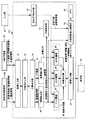
図3は、画像観察端末201の構成を示すブロック図であり、画像観察端末201は、本発明の医用画像処理装置を構成する。
FIG. 3 is a block diagram showing the configuration of the
画像観察端末201は、異なる複数の医用画像診断装置で取得した医用画像を融合処理して表示するものであり、以下の実施形態では、X線CT装置101及び超音波診断装置102で取得した画像を処理する場合について説明する。また、以下においては、心疾患の画像診断を例に説明し、心臓冠動脈の血管狭窄部位(又は閉塞部位)の候補を表示する場合について説明する。
The
図3において、画像観察端末201(医用画像処理装置)には、画像入力部41が設けられ、この画像入力部41には、超音波診断装置102及びX線CT装置101で取得した画像データが供給される。
In FIG. 3, the image observation terminal 201 (medical image processing apparatus) is provided with an
ここで、超音波診断装置102では、例えば心筋コントラストエコー法により、3次元超音波画像と3次元壁運動情報が得られ、同時に心電計により、画像収集された時の心電図情報が得られる。また、X線CT装置101により、3次元CT画像及び冠動脈造影像が得られ、同時に心電計により、画像収集された時の心電図情報が得られるものとする。
Here, in the ultrasound
画像入力部41には、超音波診断装置102から心臓部の壁情報である3次元超音波画像(壁運動情報)及びその心電図情報が入力され、かつ、X線CT装置101から心臓部の3次元CT画像(冠動脈造影像)及びその心電図情報が入力される。
The
画像入力部41は、時相合わせ部42に接続されており、時相合わせ部42では、超音波画像と3次元CT画像の各心電図情報により、時相合わせを行う。例えば、拡張末期の時相で、画像の対応関係を合わせる。
The
時相合わせ部42は、位置合わせ部43に接続されており、位置合わせ部43では、時相合わせされた超音波画像と3次元CT画像の位置合わせを行う。位置合わせ部43は、例えば、3次元CT画像の心臓全体と、一部の心臓画像となる超音波画像との相関情報を用いて位置合せする方法や、ユーザが各ボリュームに、心臓の或る特徴点3点と思われる場所を指定して位置あわせを行う方法などがある。
The
位置合わせ部43は情報作成部44及び血管抽出部45に接続されており、情報作成部44は、位置合せされた3次元超音波画像の壁運動情報を用いて、壁運動低下部位の情報を作成する。即ち、情報作成部44は、壁運動の変化が所定の閾値よりも低い部分を壁運動低下部位とみなして、心臓異常部位情報、つまり壁運動低下部位の情報を作成する。壁運動低下部位は、複数存在する場合もある。
The
血管抽出部45は、位置合せされた3次元CT画像の冠動脈像を用いて、例えば閾値設定等により、冠動脈部分を抽出する。また、これにより血管と血管以外の領域にボリュームを分割する。
The blood
情報作成部44からの壁運動低下部位の情報、及び血管抽出部45からの血管像と血管以外の領域の画像は、画像作成部46に供給される。画像作成部46は、診断用画像を作成するもので、マスク画像作成部47、SVR画像作成部48、及びMPR画像作成部49を有している。
Information on the wall motion lowering portion from the information creation unit 44 and the blood vessel image and the image of the region other than the blood vessel from the blood
マスク画像作成部47では、壁運動低下部位の情報を基に壁運動低下部位を示すマスク画像を作成し、例えば壁運動の低下領域内を予め設定された色で塗りつぶすなどのマスク処理を行う。 The mask image creation unit 47 creates a mask image indicating the wall motion decreased part based on the information on the wall motion decreased part, and performs a mask process such as painting the inside of the wall motion decreased region with a preset color.
SVR画像作成部48では、血管部分のSVR画像を作成する。また、MPR画像作成部49では、血管以外のMPR画像を作成する。SVR画像及びMPR画像の作成は、従来周知の方法を用いる。
The SVR
マスク画像作成部47、SVR画像作成部48、MPR画像作成部49には、それぞれ表示方向指示部50からの情報が入力され、ユーザが指定した表示方向の画像を作成する。表示方向指示部50は、入力部57に接続されており、ユーザが入力部57を操作することにより、表示方向を指示することができる。尚、MPR画像作成部49では、ユーザが指示した表示方向に対して垂直なMPR断面画像を作成する。また奥行き方向に対しては、ユーザが調整できる。
The mask image creation unit 47, the SVR
マスク画像作成部47、SVR画像作成部48、MPR画像作成部49でそれぞれ作成された壁運動低下部位の画像と、血管部のSVR画像と、血管以外のMPR画像は、画像合成部51に供給されて合成処理され、診断用画像が生成される(詳細は追って説明する)。
The image of the wall motion reduced part, the SVR image of the blood vessel part, and the MPR image other than the blood vessels created by the mask image creation unit 47, the SVR
一方、血管抽出部45は、芯線抽出部52に接続されており、血管抽出部45で抽出された血管部の画像(血管像)を用いて、血管芯線や血管径の情報を生成する。また血管芯線に沿って血管径を解析し、血管径が所定の閾値以上に狭く変化する部分がある場合、その位置情報を生成する。
On the other hand, the blood
また情報作成部44にて抽出された壁運動低下部位の情報と、芯線抽出部52にて作成された血管芯線と血管径の情報は、血管変異探索部53に供給される。血管変異探索部53は、血管病変部である血管狭窄(又は閉塞)部位の候補を探索し、血管狭窄部位又は血管閉塞部位候補の位置情報を生成する。また血管変異探索部53には、メモリ54が接続されている。
Further, the information on the wall motion lowering part extracted by the information creation unit 44 and the information on the blood vessel core line and the blood vessel diameter created by the core
さらに画像合成部51と血管変異探索部53は、情報付加部55に接続されている。情報付加部55は、血管変異探索部53で探索した位置情報を基に血管狭窄部位(又は閉塞部位)の候補を示す候補画像を生成し、画像合成部51からの診断用画像に重畳する。
Further, the
血管狭窄部位(又は閉塞部位)の候補の画像は、異なる形態で表示され、例えば血管狭窄部位と血管閉塞部位の画像は、それぞれ異なる色、又は異なる図形として表される。また色はユーザが任意に設定できるようにしてもよい。 The candidate images of the vascular stenosis site (or occlusion site) are displayed in different forms. For example, the images of the vascular stenosis site and the vascular occlusion site are represented as different colors or different graphics, respectively. The color may be arbitrarily set by the user.
情報付加部55の出力は表示部56に供給されて表示される。表示部56としては、液晶ディスプレイ等が用いられる。
The output of the
また、上述した入力部57は、キーボード、マウス等を有し、ユーザによって操作され、各種の指示や情報を入力することができる。また入力部57は、表示部56を利用したグラフィカル・ユーザ・インターフェース(GUI)としても機能する。
The
次に本発明の一実施形態に係る医用画像処理装置の動作について、図4、図5を参照して説明する。 Next, the operation of the medical image processing apparatus according to the embodiment of the present invention will be described with reference to FIGS.
画像入力部41には、超音波診断装置102から3次元超音波画像である心臓の壁運動情報とその心電図情報が入力される。また、X線CT装置101から3次元CT画像である冠動脈造影像とその心電図情報が入力される。
The
時相合わせ部42では、3次元超音波画像と3次元CT画像の各心電図情報により、時相合わせを行う。例えば、心電図情報の拡張末期の時相で、画像の対応関係を合わせる。
The time
位置合わせ部43では、時相合わせされた3次元超音波画像と3次元CT画像を用いて、2つのボリュームの位置合わせを行う。ここでは、例えば3次元CT画像の心臓全体と、一部の心臓画像となる3次元超音波画像との相関情報を用いた方法や、ユーザが各ボリュームに、心臓のある特徴点3点を指定して位置合せを行う方法などを用いて位置合わせを行う。
The
相関情報を用いた位置合せ方法は、例えば文献「Multimodality Image Registration by Maximization of Mutual Information IEEE TRANSACTIONS ON MEDICAL IMAGING, VOL. 16, NO. 2, APRIL 1997」に記載されている。 A registration method using correlation information is described in, for example, the document “Multimodality Image Registration by Maximization of Mutual Information IEEE TRANSACTIONS ON MEDICAL IMAGING, VOL. 16, NO. 2, APRIL 1997”.
情報作成部44では、位置合せされた3次元超音波画像の壁運動情報を用いて、壁運動の変化が或る閾値以下の部位を抽出し、壁運動低下部位の情報を作成する。 The information creation unit 44 uses the wall motion information of the aligned three-dimensional ultrasonic image to extract a portion where the wall motion change is a certain threshold value or less, and creates information on the wall motion lowered portion.
次のマスク画像作成部47では、壁運動低下部位の情報を用いて、心臓異常部位の領域を表すグラフィックス画像(マスク画像)を作成する。壁運動低下部位が複数存在する場合は、マスク画像が複数作成される。 The next mask image creation unit 47 creates a graphics image (mask image) representing the region of the abnormal heart region using the information on the wall motion decreased region. When there are a plurality of wall motion lowering portions, a plurality of mask images are created.
図4(a)は、超音波画像の一例を示すもので、壁運動低下部位の領域内を予め設定された色で塗りつぶしたマスク画像Aが表示される。尚、図4(a)において61は、心筋部を示す。
FIG. 4A shows an example of an ultrasonic image, in which a mask image A in which the region of the wall motion lowering region is filled with a preset color is displayed. In FIG. 4A,
また、血管抽出部45では、位置合せされた3次元CT画像の冠動脈像を用いて、例えば閾値処理により冠動脈部分を抽出する。また、血管と血管以外の領域にボリューム画像を分割する。
In addition, the blood
SVR画像作成部48では、抽出された血管部分のボリューム画像を用いて、血管部分のSVR画像を生成する。図4(b)はCT画像の一例を示すもので、太線で示す画像Bは、血管部分のSVR画像を示す。
The SVR
また、MPR画像作成部49では、血管以外の領域のボリューム画像を基に血管以外のMPR画像を作成する。図4(b)の61で示す画像は、心筋のMPR画像である。
Further, the MPR
マスク画像作成部47、SVR画像作成部48、及びMPR画像作成部49で作成された画像は、画像合成部51によって合成され、図4(c)で示すような診断用画像が生成される。
The images created by the mask image creation unit 47, the SVR
一方、芯線抽出部52は、血管抽出部45にて抽出された血管像を用いて、血管芯線や血管径の情報を生成する。血管芯線の抽出方法としては、例えば非特許文献1で示すような血管解析の方法を用いることができる。また血管芯線に沿って血管径を解析し、血管径が所定の閾値以上に狭く変化する部分がある場合、血管狭窄部位候補としてその位置情報を生成する。
On the other hand, the core
血管変異探索部53は、情報作成部44にて抽出された壁運動低下領域の情報と、芯線抽出部52にて作成された血管芯線と血管径の情報を用いて、血管狭窄部位又は血管閉塞部位の候補を示す位置情報を生成する。
The blood vessel
情報付加部55は、血管変異探索部53で探索した位置情報を基に血管狭窄部位又は血管閉塞部位候補の位置を示す候補画像を生成し、画像合成部51からの診断用画像に重畳する。
The
図5(a)〜(c)は、血管狭窄部位又は血管閉塞部位候補の探索過程を示した図である。血管狭窄部位又は血管閉塞部位の候補は、図5(c)で示すように表示されるが、詳細は後述する。 FIGS. 5A to 5C are diagrams showing a process for searching for a vascular stenosis site or a vascular occlusion site candidate. Candidates for vascular stenosis or vascular occlusion are displayed as shown in FIG. 5C, and will be described in detail later.
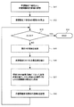
次に、血管変異探索部53における血管狭窄部位の探索方法を、図6のフローチャートをも参照して説明する。
Next, a method for searching for a vascular stenosis site in the vascular
図6のステップS1では、情報作成部44からの壁運動低下部位情報と、芯線抽出部52からの血管芯線及び血管径情報を基に血管狭窄部位の探索を開始する。
In step S <b> 1 of FIG. 6, the search for the vascular stenosis site is started based on the wall motion reduced site information from the information creation unit 44 and the vascular core line and vascular diameter information from the core
ステップS2は、壁運動低下部位情報から、壁運動低下部位の領域が何個あるかを調べるステップであり、ここでは、例えばN個あった場合を想定している。ステップS3は、壁運動低下部位の領域AがN個(A=1,2,3…N)のとき、A=Nか否かを判断する。 Step S2 is a step of examining how many regions of the wall motion lowering portion are present from the wall motion lowering portion information. Here, for example, it is assumed that there are N regions. Step S3 determines whether or not A = N when there are N (A = 1, 2, 3... N) regions A of the wall motion lowering sites.
ステップS3がYESであれば、終了ステップS4に移行し、ステップS3がNO(A≠N)であれば、次のステップS5に進む。ステップS5では、領域Aをある設定回数分、拡張する。領域拡張は従来からある領域拡張法を用いて行われる。 If step S3 is YES, the process proceeds to end step S4, and if step S3 is NO (A ≠ N), the process proceeds to the next step S5. In step S5, the area A is expanded a certain number of times. Region expansion is performed using a conventional region expansion method.
図5(a)の点線Cは、領域Aを拡張した領域を示している。領域の拡張は、壁運動低下領域Aを核として、それに隣接する血管の場所を抽出するために行う。なお、領域拡張を行う回数はユーザが調整可能にしてもよい。 A dotted line C in FIG. 5A indicates an area obtained by expanding the area A. The region is expanded in order to extract the location of the blood vessel adjacent to the wall motion lowering region A as a nucleus. Note that the number of times of area expansion may be adjustable by the user.
次のステップS6では、拡張領域C内の血管芯線部分を抽出する。図5(b)は抽出した血管芯線B’を示すものであり、領域C内の血管芯線と、それに繋がる領域C外の血管芯線を示す。またこのとき、領域Cの境界で切断された血管芯線の位置(図5(b)の点X)の情報をメモリ54に記憶しておく。
In the next step S6, the blood vessel core line portion in the expanded region C is extracted. FIG. 5B shows the extracted blood vessel core line B ', and shows the blood vessel core wire in the region C and the blood vessel core wire outside the region C connected thereto. At this time, information on the position of the blood vessel core line cut at the boundary of the region C (point X in FIG. 5B) is stored in the
ステップS7では、先ず領域C内に存在する血管領域(冠動脈)ついて、血管芯線B’に沿って血管径の変化を探索する。血管径が或る閾値以上に変化して狭くなっている場合、血管狭窄部位の候補Dとして、その位置情報をメモリ54に記憶する。尚、閾値はユーザが調整できるようにしてもよい。
In step S7, the blood vessel region (coronary artery) existing in region C is first searched for a change in blood vessel diameter along the blood vessel core line B '. If the blood vessel diameter is narrower than a certain threshold, the position information is stored in the
次に、拡張領域Cの境界で切断された血管芯線の端点(図5(b)X点)から、それに繋がる領域C外の血管領域(冠動脈)に対して血管芯線B’沿って血管径の変化を探索する。そして血管径が或る閾値以上に変化して狭くなっている場合、同様に血管狭窄部位の候補Dとして、その位置情報をメモリ54に記憶する。
Next, from the end point (point X in FIG. 5 (b)) of the blood vessel core line cut at the boundary of the expansion region C, the blood vessel diameter along the blood vessel core line B ′ with respect to the blood vessel region (coronary artery) outside the region C connected to the end point. Explore changes. When the blood vessel diameter changes to a certain threshold value or more and becomes narrow, the position information is similarly stored in the
ステップS8は、血管狭窄部位候補Dの位置情報を記憶するステップである。壁運動低下部位がN個ある場合は、ステップS3に戻って同様の処理をN回繰り返し、すべての壁運動低下部位において血管狭窄部位の候補を探索して記憶する。 Step S8 is a step of storing position information of the vascular stenosis region candidate D. If there are N wall motion reduction sites, the process returns to step S3 and the same process is repeated N times, and vascular stenosis site candidates are searched and stored in all wall motion reduction sites.
また血管狭窄部位候補の画像は、表示部55に表示される。図5(c)は、情報付加部55の出力画像を拡大して示すものであり、血管狭窄部位候補Dの画像は、図5(c)の丸印で示すように所定の色で表示される。こうして拡張領域Cを中心にして散在する血管狭窄部位の候補Dを分かりやすく表示することができる。
An image of a candidate vascular stenosis site is displayed on the
次に、血管変異探索部53における血管閉塞部位の探索方法を、図7のフローチャートを参照して説明する。
Next, a method for searching for a vascular occlusion site in the vascular
図7のステップS11〜S16までは、図5のステップS1〜S6と同様の処理を行うものであり、ステップS11は、情報作成部44からの壁運動低下部位情報と、芯線抽出部52からの血管芯線及び血管径情報を基に血管閉塞部位の探索を開始する。
Steps S11 to S16 in FIG. 7 are performed in the same manner as steps S1 to S6 in FIG. 5. Step S11 includes the wall motion lowering part information from the information creation unit 44 and the core
ステップS12では、壁運動低下部位情報から、壁運動低下部位の領域Aが何個あるかを調べる。ここでは、例えばN個あった場合を想定する。ステップS13では、A=Nか否かを判断する。 In step S12, it is examined how many areas A of the wall motion lowering part are present from the wall motion lowering part information. Here, it is assumed that there are N, for example. In step S13, it is determined whether A = N.
ステップS13がYESであれば、終了ステップS14に移行し、NO(A≠N)であれば、次のステップS15に進む。ステップS15では、領域Aをある設定回数分、拡張する。図5(a)の点線Cは拡張された領域を示す。 If step S13 is YES, the process proceeds to end step S14, and if NO (A ≠ N), the process proceeds to the next step S15. In step S15, the area A is expanded a certain number of times. A dotted line C in FIG. 5A indicates an expanded area.
次のステップS16では、拡張領域C内の血管芯線部分を抽出する。図5(b)は抽出した血管芯線部分B’を示す。ここでも、図5(b)の領域Cの境界で切断された血管芯線の位置(点X)の情報をメモリ54に記憶しておく。 In the next step S16, the blood vessel core line portion in the expanded region C is extracted. FIG. 5B shows the extracted blood vessel core portion B ′. Also in this case, information on the position (point X) of the blood vessel core line cut at the boundary of the region C in FIG.
ステップS17では、先ず領域C内に存在する血管領域(冠動脈)について、血管芯線B’に沿って終端となる部分を探索する。ただし、領域Cの境界で切断された血管芯線の位置Xは除く。そして抽出された血管終端の部分を、血管閉塞部位の候補Eとして、その位置情報をメモリ54に記憶する。
In step S17, first, the blood vessel region (coronary artery) existing in the region C is searched for a portion that terminates along the blood vessel core line B '. However, the position X of the blood vessel core line cut at the boundary of the region C is excluded. Then, the extracted blood vessel terminal portion is stored in the
次に、境界Cの境界で切断された血管芯線の端点Xから、領域C外の血管に対して、血管芯線B’に沿って血管終端となる位置を探索する。そして抽出された血管閉塞部位の候補Eとして、その位置情報をメモリ54に記憶する(ステップS18)。また境界Cで切断された血管芯線の端点全てについて探索を行う。
Next, from the end point X of the blood vessel core line cut at the boundary of the boundary C, a position that becomes the blood vessel end along the blood vessel core line B ′ is searched for blood vessels outside the region C. And the positional information is memorize | stored in the
壁運動低下部位AがN個ある場合は、ステップS13に戻って同様の処理をN回繰り返し、すべての壁運動低下部位Aにおいて血管閉塞部位の候補Eを探索して記憶する。 When there are N wall motion reduction sites A, the process returns to step S13 and the same processing is repeated N times, and the candidate E for the vascular occlusion site is searched and stored in all wall motion reduction sites A.
血管閉塞部位候補の画像は、表示部55に表示され、図5(c)の矩形印Eで示すように所定の色で表示される。こうして拡張領域Cを中心にして散在する血管閉塞部位の候補Eを分かりやすく表示することができる。
The image of the candidate vessel occlusion site is displayed on the
尚、血管狭窄部位候補Dと血管閉塞部位候補Eの画像は、それぞれ異なる色、又は異なる形状として表されるが、色や形状はユーザが任意に設定できるようにしてもよい。 The images of the vascular stenosis region candidate D and the vascular occlusion region candidate E are represented as different colors or different shapes, but the color and shape may be arbitrarily set by the user.
以上、述べたように本発明の実施形態に係る医用画像処理装置によれば、例えば超音波画像とCT画像を合成して表示し、さらに血管狭窄又は閉塞部位の候補となる画像を付加して表示することができるため、疾患部位を診断する際の診断精度を向上させることができる。 As described above, according to the medical image processing apparatus according to the embodiment of the present invention, for example, an ultrasonic image and a CT image are combined and displayed, and an image that is a candidate for vascular stenosis or occlusion is added. Since it can display, the diagnostic accuracy at the time of diagnosing a diseased part can be improved.
尚、以上の説明では、心臓の異常部位情報(壁運動の低下部位情報)を得るために、超音波診断装置102を用いる例について説明したが、これに限らず、MRI装置103、核医学診断装置(SPECT)を用いるようにしても良い。また3次元血管造影像を得るために、X線CT装置101を用いる例について説明したが、これに限らず、MRI装置103や、X線診断装置104を用いるようにしても良い。
In the above description, an example in which the ultrasonic
また、本発明の医用画像処理装置は、画像観察端末201としてユニット化されたものを例に説明したが、こりに限らず、X線CT装置101や、超音波診断装置102内に組み込んで構成することもできる。
Further, the medical image processing apparatus of the present invention has been described as an example of a unitized
例えば、X線CT装置101に組み込む場合は、図2の画像データ処理部28に、図3で示す画像入力部41から情報付加部55までの機能ブロックを内蔵させ、図3の表示部56及び入力部57の機能は、図2の表示部29及び入力部25で代用させれば良い。そしてネットワークインタフェース31を介して超音波診断装置102からの画像データを取り込むようにすれば良い。
For example, when incorporated in the
また、血管狭窄部位又は血管閉塞部位の候補画像D,Eを表示した際に、ユーザがその表示位置を選択(クリック)することよって、選択した部位の周辺の血管芯線に沿った曲面MPR像とクロスカット像を別窓で表示するようにしても良い。 Further, when the candidate images D and E of the vascular stenosis site or the vascular occlusion site are displayed, the user selects (clicks) the display position so that the curved MPR image along the vascular core line around the selected site is displayed. The cross cut image may be displayed in a separate window.
また本発明の実施形態は以上の説明に限定されることなく、特許請求の範囲を逸脱しない範囲で種々の変形が可能である。 The embodiment of the present invention is not limited to the above description, and various modifications can be made without departing from the scope of the claims.
100…ネットワーク
101…X線CT装置
102…超音波診断装置
200…ファイルサーバ
201…画像観察端末(医用画像処理装置)
41…画像入力部
42…時相合わせ部
43…位置合わせ部
44…情報作成部
45…血管抽出部
46…画像作成部
47…マスク画像作成部
48…SVR画像作成部
49…MPR画像作成部
50…表示方向指示部
51…画像合成部
52…芯線抽出部
53…血管変異部位探索部
54…メモリ
55…情報付加部
56…表示部
57…入力部
DESCRIPTION OF
DESCRIPTION OF
Claims (20)
第1の医用画像診断装置によって取得した、心臓壁情報を含む第1の画像情報と、第2の医用画像診断装置によって取得した、心臓部の3次元画像を含む第2の画像情報を取り込む画像入力部と、
前記第1の画像情報に含まれる前記心臓壁情報を基に心臓異常部位を推定し、異常部位情報を作成する情報作成部と、
前記3次元画像に含まれる血管部の画像を抽出する血管抽出部と、
前記異常部位情報と前記血管部の画像を処理して診断用画像を作成する画像作成部と、
前記異常部位情報と前記血管部の画像を取り込み、前記心臓異常部位を核とする所定範囲の血管領域を中心に血管病変部の候補を探索する血管変異探索部と、
前記血管病変部の候補を表す候補画像を作成し、前記診断用画像に前記候補画像を付加して表示部に表示する情報付加部と、を具備したことを特徴とする医用画像処理装置。 A medical image processing apparatus that can be used for diagnosis of heart disease,
An image capturing the first image information including the heart wall information acquired by the first medical image diagnostic apparatus and the second image information including the three-dimensional image of the heart acquired by the second medical image diagnostic apparatus. An input section;
An information creation unit that estimates a cardiac abnormal site based on the heart wall information included in the first image information and creates abnormal site information;
A blood vessel extraction unit that extracts an image of a blood vessel part included in the three-dimensional image;
An image creation unit that creates a diagnostic image by processing the abnormal site information and the image of the blood vessel;
A blood vessel mutation search unit that takes in the abnormal part information and the image of the blood vessel part, and searches for a candidate for a blood vessel lesion part around a blood vessel region in a predetermined range having the heart abnormal part as a nucleus;
A medical image processing apparatus comprising: an information adding unit that generates a candidate image representing a candidate for the vascular lesion site, adds the candidate image to the diagnostic image, and displays the candidate image on a display unit.
第1の医用画像診断装置によって取得した心臓壁情報を含む第1の画像情報と、第2の医用画像診断装置によって取得した心臓部の3次元画像を含む第2の画像情報を取り込み、
前記第1の画像情報に含まれる前記心臓壁情報を基に心臓異常部位を推定して異常部位情報を作成し、
前記3次元画像に含まれる血管部の画像を抽出し、
前記異常部位情報と前記血管部の画像を処理して診断用画像を作成し、
前記異常部位情報と前記血管部の画像を取り込み、前記心臓異常部位を核とする所定範囲の血管領域を中心に血管病変部の候補を探索し、
前記血管病変部の候補を表す候補画像を作成し前記診断用画像に付加して表示部に表示することを特徴とする医用画像処理方法。 A medical image processing method usable for diagnosis of heart disease,
First image information including heart wall information acquired by the first medical image diagnostic apparatus and second image information including a three-dimensional image of the heart acquired by the second medical image diagnostic apparatus are captured,
Based on the heart wall information included in the first image information, the abnormal site information is estimated by estimating the abnormal heart site,
Extracting an image of a blood vessel portion included in the three-dimensional image;
Process the abnormal site information and the image of the blood vessel to create a diagnostic image,
The abnormal part information and the image of the blood vessel part are captured, and a candidate for a blood vessel lesion part is searched around a blood vessel region in a predetermined range centered on the heart abnormal part,
A medical image processing method, wherein a candidate image representing a candidate for the vascular lesion is created, added to the diagnostic image, and displayed on a display unit.
前記所定範囲内における血管領域と、前記所定範囲内の血管領域に繋がる前記所定範囲外の血管領域について、前記血管芯線に沿って血管径を判別し、
前記血管径の大きさが急激に変化した部分を、血管狭窄部位の候補として探索することを特徴とする請求項13記載の医用画像処理方法。 When searching for a candidate for the vascular lesion, extract a vascular core from the vascular image,
For a blood vessel region within the predetermined range and a blood vessel region outside the predetermined range connected to the blood vessel region within the predetermined range, determine a blood vessel diameter along the blood vessel core line,
The medical image processing method according to claim 13, wherein a portion in which the size of the blood vessel diameter has rapidly changed is searched for as a candidate for a blood vessel stenosis site.
前記所定範囲内における血管領域と、前記所定範囲内の血管領域に繋がる前記所定範囲外の血管領域について、前記血管芯線に沿う血管終端部分を判別し、
前記血管終端部分を、血管閉塞部位の候補として探索することを特徴とする請求項13記載の医用画像処理方法。 When searching for a candidate for the vascular lesion, extract a vascular core from the vascular image,
For a blood vessel region within the predetermined range and a blood vessel region outside the predetermined range connected to the blood vessel region within the predetermined range, determine a blood vessel terminal portion along the blood vessel core line,
The medical image processing method according to claim 13, wherein the blood vessel terminal portion is searched as a candidate for a blood vessel occlusion site.
前記被検体を撮影して、前記第1の画像情報及び前記第2の画像情報のいずれか一方を取得する撮影部と、
前記撮影部で取得した前記一方の画像情報と、他の医用画像診断装置で取得した他方の画像情報を取り込む画像入力部と、
前記第1の画像情報に含まれる前記心臓壁情報を基に心臓異常部位を推定し、異常部位情報を作成する情報作成部と、
前記3次元画像に含まれる血管部の画像を抽出する血管抽出部と、
前記異常部位情報と前記血管部の画像を処理して診断用画像を作成する画像作成部と、
前記異常部位情報と前記血管部の画像を取り込み、前記心臓異常部位を核とする所定範囲の血管領域を中心に血管病変部の候補を探索する血管変異探索部と、
前記血管病変部の候補を表す候補画像を作成し、前記診断用画像に前記候補画像を付加する情報付加部と、
前記情報付加部から出力される画像情報を表示する表示部と、を具備したことを特徴とする医用画像診断装置。 A medical image diagnostic apparatus capable of diagnosing a heart disease using first image information including heart wall information of a subject and second image information including a three-dimensional image of a heart part,
An imaging unit that images the subject and acquires one of the first image information and the second image information;
An image input unit that captures the one image information acquired by the imaging unit and the other image information acquired by another medical image diagnostic apparatus;
An information creation unit that estimates a cardiac abnormal site based on the heart wall information included in the first image information and creates abnormal site information;
A blood vessel extraction unit that extracts an image of a blood vessel part included in the three-dimensional image;
An image creation unit that creates a diagnostic image by processing the abnormal site information and the image of the blood vessel;
A blood vessel mutation search unit that takes in the abnormal part information and the image of the blood vessel part, and searches for a candidate for a blood vessel lesion part around a blood vessel region in a predetermined range having the heart abnormal part as a nucleus;
Creating a candidate image representing a candidate for the vascular lesion, and adding the candidate image to the diagnostic image;
And a display unit for displaying image information output from the information adding unit.
Priority Applications (1)
| Application Number | Priority Date | Filing Date | Title |
|---|---|---|---|
| JP2007282069A JP2009106530A (en) | 2007-10-30 | 2007-10-30 | Medical image processing apparatus, medical image processing method, and medical image diagnostic apparatus |
Applications Claiming Priority (1)
| Application Number | Priority Date | Filing Date | Title |
|---|---|---|---|
| JP2007282069A JP2009106530A (en) | 2007-10-30 | 2007-10-30 | Medical image processing apparatus, medical image processing method, and medical image diagnostic apparatus |
Publications (1)
| Publication Number | Publication Date |
|---|---|
| JP2009106530A true JP2009106530A (en) | 2009-05-21 |
Family
ID=40775736
Family Applications (1)
| Application Number | Title | Priority Date | Filing Date |
|---|---|---|---|
| JP2007282069A Withdrawn JP2009106530A (en) | 2007-10-30 | 2007-10-30 | Medical image processing apparatus, medical image processing method, and medical image diagnostic apparatus |
Country Status (1)
| Country | Link |
|---|---|
| JP (1) | JP2009106530A (en) |
Cited By (12)
| Publication number | Priority date | Publication date | Assignee | Title |
|---|---|---|---|---|
| JP2011031040A (en) * | 2009-07-31 | 2011-02-17 | Medison Co Ltd | System and method for providing two-dimensional ct image corresponding to two-dimensional ultrasonic image |
| JP2011139821A (en) * | 2010-01-08 | 2011-07-21 | Toshiba Corp | Medical image diagnostic apparatus |
| JP2011177494A (en) * | 2010-02-04 | 2011-09-15 | Toshiba Corp | Image processing apparatus, ultrasonic diagnostic apparatus, and image processing method |
| JP2012045285A (en) * | 2010-08-30 | 2012-03-08 | Ge Medical Systems Global Technology Co Llc | Ultrasonograph and control program of the same |
| EP2442276A1 (en) * | 2010-09-15 | 2012-04-18 | Kabushiki Kaisha Toshiba | Medical image processing apparatus and medical image processing method |
| JP2014030537A (en) * | 2012-08-02 | 2014-02-20 | Toshiba Corp | Image processing apparatus and magnetic resonance imaging apparatus |
| CN103908254A (en) * | 2013-01-03 | 2014-07-09 | 西门子公司 | Method and system for lesion candidate detection |
| JP2015517868A (en) * | 2012-05-31 | 2015-06-25 | コーニンクレッカ フィリップス エヌ ヴェ | Ultrasound imaging system and method for image guidance procedures |
| WO2018212231A1 (en) * | 2017-05-16 | 2018-11-22 | テルモ株式会社 | Image processing device, image processing system, and image processing method |
| US10368821B2 (en) | 2014-07-16 | 2019-08-06 | Canon Medical Systems Corporation | Image processing apparatus, medical image diagnostic apparatus and image processing method |
| WO2019176532A1 (en) * | 2018-03-15 | 2019-09-19 | テルモ株式会社 | Image processing device, image processing method, calculation method, and program |
| CN112674736A (en) * | 2021-01-08 | 2021-04-20 | 博动医学影像科技(上海)有限公司 | Monitoring display method and system for automatically evaluating deformation of blood vessel |
-
2007
- 2007-10-30 JP JP2007282069A patent/JP2009106530A/en not_active Withdrawn
Cited By (16)
| Publication number | Priority date | Publication date | Assignee | Title |
|---|---|---|---|---|
| JP2011031040A (en) * | 2009-07-31 | 2011-02-17 | Medison Co Ltd | System and method for providing two-dimensional ct image corresponding to two-dimensional ultrasonic image |
| JP2011139821A (en) * | 2010-01-08 | 2011-07-21 | Toshiba Corp | Medical image diagnostic apparatus |
| JP2011177494A (en) * | 2010-02-04 | 2011-09-15 | Toshiba Corp | Image processing apparatus, ultrasonic diagnostic apparatus, and image processing method |
| JP2012045285A (en) * | 2010-08-30 | 2012-03-08 | Ge Medical Systems Global Technology Co Llc | Ultrasonograph and control program of the same |
| JP2015164560A (en) * | 2010-09-15 | 2015-09-17 | 株式会社東芝 | Medical image processor and medical image processing method |
| EP2442276A1 (en) * | 2010-09-15 | 2012-04-18 | Kabushiki Kaisha Toshiba | Medical image processing apparatus and medical image processing method |
| CN102415898A (en) * | 2010-09-15 | 2012-04-18 | 株式会社东芝 | Medical image processing apparatus and medical image processing method |
| US8649584B2 (en) | 2010-09-15 | 2014-02-11 | Kabushiki Kaisha Toshiba | Medical image processing apparatus and medical image processing method |
| JP2015517868A (en) * | 2012-05-31 | 2015-06-25 | コーニンクレッカ フィリップス エヌ ヴェ | Ultrasound imaging system and method for image guidance procedures |
| JP2014030537A (en) * | 2012-08-02 | 2014-02-20 | Toshiba Corp | Image processing apparatus and magnetic resonance imaging apparatus |
| CN103908254A (en) * | 2013-01-03 | 2014-07-09 | 西门子公司 | Method and system for lesion candidate detection |
| US9378551B2 (en) | 2013-01-03 | 2016-06-28 | Siemens Aktiengesellschaft | Method and system for lesion candidate detection |
| US10368821B2 (en) | 2014-07-16 | 2019-08-06 | Canon Medical Systems Corporation | Image processing apparatus, medical image diagnostic apparatus and image processing method |
| WO2018212231A1 (en) * | 2017-05-16 | 2018-11-22 | テルモ株式会社 | Image processing device, image processing system, and image processing method |
| WO2019176532A1 (en) * | 2018-03-15 | 2019-09-19 | テルモ株式会社 | Image processing device, image processing method, calculation method, and program |
| CN112674736A (en) * | 2021-01-08 | 2021-04-20 | 博动医学影像科技(上海)有限公司 | Monitoring display method and system for automatically evaluating deformation of blood vessel |
Similar Documents
| Publication | Publication Date | Title |
|---|---|---|
| JP2009106530A (en) | Medical image processing apparatus, medical image processing method, and medical image diagnostic apparatus | |
| JP6073971B2 (en) | Medical image processing device | |
| US7813785B2 (en) | Cardiac imaging system and method for planning minimally invasive direct coronary artery bypass surgery | |
| JP4653542B2 (en) | Image processing device | |
| JP5591440B2 (en) | Medical image display device | |
| JP5491914B2 (en) | Image display apparatus and X-ray diagnostic apparatus | |
| JP5196751B2 (en) | Computer-aided diagnosis device | |
| US20070247454A1 (en) | 3D visualization with synchronous X-ray image display | |
| CN106485691B (en) | Information processing apparatus, information processing system, and information processing method | |
| JP2011092681A (en) | Medical image processor, method, and program | |
| JP7027046B2 (en) | Medical image imaging device and method | |
| JP5934071B2 (en) | Apparatus, method and program for searching for shortest path of tubular structure | |
| JP2013244211A (en) | Medical image processor, medical image processing method and control program | |
| JP2009028161A (en) | Medical image display device and method | |
| JP4686279B2 (en) | Medical diagnostic apparatus and diagnostic support apparatus | |
| JP2010154982A (en) | X-ray computer tomographic imaging apparatus and image processor | |
| JP4996128B2 (en) | Medical image processing apparatus and medical image processing method | |
| JP5380231B2 (en) | Medical image display apparatus and method, and program | |
| JP2011206239A (en) | Medical image processor, method, and program | |
| JP6797557B2 (en) | Medical image diagnostic equipment, medical image processing equipment and image display program | |
| JP2009148422A (en) | Medical image processor and medical image photographing device | |
| JP2008018016A (en) | Medical image processing equipment and method | |
| JP6734111B2 (en) | Finding information creation device and system | |
| JP2011206240A (en) | Medical image display device, method, and program | |
| JP5305635B2 (en) | Medical image display device |
Legal Events
| Date | Code | Title | Description |
|---|---|---|---|
| A300 | Application deemed to be withdrawn because no request for examination was validly filed |
Free format text: JAPANESE INTERMEDIATE CODE: A300 Effective date: 20110104 |