JP2009103304A - Hydraulic control valve for construction machine - Google Patents
Hydraulic control valve for construction machine Download PDFInfo
- Publication number
- JP2009103304A JP2009103304A JP2008268778A JP2008268778A JP2009103304A JP 2009103304 A JP2009103304 A JP 2009103304A JP 2008268778 A JP2008268778 A JP 2008268778A JP 2008268778 A JP2008268778 A JP 2008268778A JP 2009103304 A JP2009103304 A JP 2009103304A
- Authority
- JP
- Japan
- Prior art keywords
- passage
- regeneration
- spool
- hydraulic
- pressure
- Prior art date
- Legal status (The legal status is an assumption and is not a legal conclusion. Google has not performed a legal analysis and makes no representation as to the accuracy of the status listed.)
- Pending
Links
Images


Classifications
-
- F—MECHANICAL ENGINEERING; LIGHTING; HEATING; WEAPONS; BLASTING
- F15—FLUID-PRESSURE ACTUATORS; HYDRAULICS OR PNEUMATICS IN GENERAL
- F15B—SYSTEMS ACTING BY MEANS OF FLUIDS IN GENERAL; FLUID-PRESSURE ACTUATORS, e.g. SERVOMOTORS; DETAILS OF FLUID-PRESSURE SYSTEMS, NOT OTHERWISE PROVIDED FOR
- F15B13/00—Details of servomotor systems ; Valves for servomotor systems
- F15B13/02—Fluid distribution or supply devices characterised by their adaptation to the control of servomotors
- F15B13/04—Fluid distribution or supply devices characterised by their adaptation to the control of servomotors for use with a single servomotor
- F15B13/0401—Valve members; Fluid interconnections therefor
- F15B13/0402—Valve members; Fluid interconnections therefor for linearly sliding valves, e.g. spool valves
- F15B13/0403—Valve members; Fluid interconnections therefor for linearly sliding valves, e.g. spool valves a secondary valve member sliding within the main spool, e.g. for regeneration flow
-
- E—FIXED CONSTRUCTIONS
- E02—HYDRAULIC ENGINEERING; FOUNDATIONS; SOIL SHIFTING
- E02F—DREDGING; SOIL-SHIFTING
- E02F9/00—Component parts of dredgers or soil-shifting machines, not restricted to one of the kinds covered by groups E02F3/00 - E02F7/00
- E02F9/20—Drives; Control devices
- E02F9/22—Hydraulic or pneumatic drives
- E02F9/2264—Arrangements or adaptations of elements for hydraulic drives
- E02F9/2267—Valves or distributors
-
- E—FIXED CONSTRUCTIONS
- E02—HYDRAULIC ENGINEERING; FOUNDATIONS; SOIL SHIFTING
- E02F—DREDGING; SOIL-SHIFTING
- E02F9/00—Component parts of dredgers or soil-shifting machines, not restricted to one of the kinds covered by groups E02F3/00 - E02F7/00
- E02F9/20—Drives; Control devices
- E02F9/22—Hydraulic or pneumatic drives
- E02F9/2264—Arrangements or adaptations of elements for hydraulic drives
- E02F9/2271—Actuators and supports therefor and protection therefor
-
- F—MECHANICAL ENGINEERING; LIGHTING; HEATING; WEAPONS; BLASTING
- F15—FLUID-PRESSURE ACTUATORS; HYDRAULICS OR PNEUMATICS IN GENERAL
- F15B—SYSTEMS ACTING BY MEANS OF FLUIDS IN GENERAL; FLUID-PRESSURE ACTUATORS, e.g. SERVOMOTORS; DETAILS OF FLUID-PRESSURE SYSTEMS, NOT OTHERWISE PROVIDED FOR
- F15B13/00—Details of servomotor systems ; Valves for servomotor systems
- F15B13/02—Fluid distribution or supply devices characterised by their adaptation to the control of servomotors
- F15B13/021—Valves for interconnecting the fluid chambers of an actuator
-
- F—MECHANICAL ENGINEERING; LIGHTING; HEATING; WEAPONS; BLASTING
- F16—ENGINEERING ELEMENTS AND UNITS; GENERAL MEASURES FOR PRODUCING AND MAINTAINING EFFECTIVE FUNCTIONING OF MACHINES OR INSTALLATIONS; THERMAL INSULATION IN GENERAL
- F16K—VALVES; TAPS; COCKS; ACTUATING-FLOATS; DEVICES FOR VENTING OR AERATING
- F16K11/00—Multiple-way valves, e.g. mixing valves; Pipe fittings incorporating such valves
- F16K11/02—Multiple-way valves, e.g. mixing valves; Pipe fittings incorporating such valves with all movable sealing faces moving as one unit
-
- Y—GENERAL TAGGING OF NEW TECHNOLOGICAL DEVELOPMENTS; GENERAL TAGGING OF CROSS-SECTIONAL TECHNOLOGIES SPANNING OVER SEVERAL SECTIONS OF THE IPC; TECHNICAL SUBJECTS COVERED BY FORMER USPC CROSS-REFERENCE ART COLLECTIONS [XRACs] AND DIGESTS
- Y10—TECHNICAL SUBJECTS COVERED BY FORMER USPC
- Y10T—TECHNICAL SUBJECTS COVERED BY FORMER US CLASSIFICATION
- Y10T137/00—Fluid handling
- Y10T137/8593—Systems
- Y10T137/87169—Supply and exhaust
- Y10T137/87177—With bypass
- Y10T137/87185—Controlled by supply or exhaust valve
-
- Y—GENERAL TAGGING OF NEW TECHNOLOGICAL DEVELOPMENTS; GENERAL TAGGING OF CROSS-SECTIONAL TECHNOLOGIES SPANNING OVER SEVERAL SECTIONS OF THE IPC; TECHNICAL SUBJECTS COVERED BY FORMER USPC CROSS-REFERENCE ART COLLECTIONS [XRACs] AND DIGESTS
- Y10—TECHNICAL SUBJECTS COVERED BY FORMER USPC
- Y10T—TECHNICAL SUBJECTS COVERED BY FORMER US CLASSIFICATION
- Y10T137/00—Fluid handling
- Y10T137/8593—Systems
- Y10T137/87169—Supply and exhaust
- Y10T137/87217—Motor
- Y10T137/87225—Fluid motor
-
- Y—GENERAL TAGGING OF NEW TECHNOLOGICAL DEVELOPMENTS; GENERAL TAGGING OF CROSS-SECTIONAL TECHNOLOGIES SPANNING OVER SEVERAL SECTIONS OF THE IPC; TECHNICAL SUBJECTS COVERED BY FORMER USPC CROSS-REFERENCE ART COLLECTIONS [XRACs] AND DIGESTS
- Y10—TECHNICAL SUBJECTS COVERED BY FORMER USPC
- Y10T—TECHNICAL SUBJECTS COVERED BY FORMER US CLASSIFICATION
- Y10T137/00—Fluid handling
- Y10T137/8593—Systems
- Y10T137/87169—Supply and exhaust
- Y10T137/87233—Biased exhaust valve
- Y10T137/87241—Biased closed
Abstract
Description
本発明は、掘削機などのような建設機械に使われる再生機能を備えた油圧制御弁に係る。さらに詳細には、油圧ポンプの吐出流量、作業装置の駆動位置、駆動速度、再生流量及び帰還流量が変わっても、供給通路の圧力及び流量変化に対する再生通路の圧力を一定に維持することができるようにした建設機械用油圧制御弁に係る。 The present invention relates to a hydraulic control valve having a regeneration function used for a construction machine such as an excavator. More specifically, even if the discharge flow rate of the hydraulic pump, the drive position of the work device, the drive speed, the regeneration flow rate, and the return flow rate change, the pressure of the supply passage and the pressure of the regeneration passage with respect to the flow rate can be kept constant. The present invention relates to a hydraulic control valve for a construction machine.
一般に、油圧回路における再生(regeneration)とは、アクチュエータ(油圧シリンダなど)の帰還側から油圧タンク側に戻る作動油を再生弁を介してアクチュエータの供給側流路に補充供給することによって、より速い作業速度を確保することができ、且つ、エネルギー効率を向上できる。また、アクチュエータの駆動速度が速くなり、供給側に生じる流量不足によるキャビテーション(空洞現象)の発生を防止することによって、各部品の使用寿命を延長することができ、且つ、顧客の不満を解消することができる技術である。 In general, regeneration in a hydraulic circuit is faster by replenishing and supplying hydraulic fluid that returns from the return side of an actuator (such as a hydraulic cylinder) to the hydraulic tank side through a regeneration valve to the supply side flow path of the actuator. Work speed can be ensured and energy efficiency can be improved. In addition, the actuator drive speed increases, preventing the occurrence of cavitation (cavity phenomenon) due to insufficient flow rate on the supply side, thereby extending the service life of each part and eliminating customer dissatisfaction. Technology that can.
以下、図1ないし図3に示したように従来技術による建設機械用油圧制御弁の使用例について説明する。 Hereinafter, a usage example of a hydraulic control valve for a construction machine according to the prior art as shown in FIGS. 1 to 3 will be described.
可変容量型油圧ポンプ1から吐き出される作動油は、供給ライン2を経由し、チェック弁Cを図に於いて上方向に加圧し、弁体内に形成された供給通路に供給される。外部からパイロット信号圧Piの供給によりスプール7が左側又は右側に切り換えられることによって、供給通路6に供給された作動油は、第1ポート又は第2ポート5に供給される。
The hydraulic oil discharged from the variable displacement
この際、第1ポート4は、油圧シリンダ8のラージチェンバー8aに連結され、第2ポート5は、スモールチェンバー8bに連結されているので、スプール7が、図において右側方向に切り換えられる場合には、供給通路6の作動油は、第1ポート4を通過し、ラージチェンバー8に供給される。これにより、油圧シリンダ8は伸長駆動するので、スモールチェンバー8bから排出された作動油は、第2ポート5を経由し、タンク通路10bを介して油圧タンクTに戻ることになる。
At this time, since the
一方、スプール7が、図において左側方向に切り換えられる場合には、油圧ポンプ1からの作動油は、供給通路6、第2ポート5を経由し、スモールチェンバー8bに供給される。油圧シリンダ8の収縮駆動によりラージチェンバー8aから排出された作動油は、第1ポート4を経由し、タンク通路10aを介して油圧タンクTに戻る。
On the other hand, when the
この際、油圧シリンダ8の伸張駆動時、スモールチェンバー8bから排出された作動油の一部は再生弁12により供給通路6側に供給されるので、油圧タンクTに戻る作動油の一部を油圧シリンダ8の供給側に供給し、使用することによって、エネルギー効率を高めることができる。また、油圧シリンダ8に供給される作動油の不足によるキャビテーションの発生を防止することができる。
At this time, when the
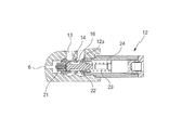
図2及び図3に示したように、スプール7が、図において右側方向に切り換えられると(油圧シリンダ8が伸張駆動する場合)、スモールチェンバー8bから排出された作動油は、第2ポート5を通過し、第1再生通路13-通路14-帰還通路16をこの順に経由し、タンク通路10bに移動することになる。
As shown in FIGS. 2 and 3, when the
この際、帰還通路16の断面積が小さくなっている(通路孔の直径が小さい)ので、第1再生通路13には圧力が形成されることになる。この圧力が第2再生通路15(スプール7の内部に形成)の圧力より相対的に高い場合、スプール7の内部に形成されたポペット17が、図において右側方向に移動するので、第1再生通路13の作動油が第2再生通路15を介して供給通路6に供給される。つまり、油圧タンクTに戻る作動油の一部を供給側に補充供給することが可能となる。
At this time, since the sectional area of the
しかし、油圧シリンダ8の作動にパワーを大きく要求する場合(負荷が大きく生じた場合)には、第1ポート4の圧力が同一条件であり、第2ポート5の背圧が少ないほど(第1再生通路13の背圧が少ない場合をいう)油圧シリンダ8はより強いパワーを発揮することができる。
However, when a large amount of power is required for the operation of the hydraulic cylinder 8 (when a large load is generated), the pressure of the
即ち、図3に示したように、供給通路6の圧力が設定値以上である場合は、供給通路6の圧力で加圧されるピストン21により再生スプール22を、図において右側方向に移動させる。これにより、帰還通路16の開口量が漸次大きくなるので(作動油の通過面積の変化をいう)、第1再生通路13の背圧が減少し、油圧シリンダ8は、力強いパワーを発揮することができる。
That is, as shown in FIG. 3, when the pressure in the
即ち、帰還通路16の開口量を可変させる再生スプール22は、第1弾性部材23(圧縮コイルばねが用いられる)により弾性的に支持され、供給通路6の圧力により移動するピストン21が再生スプール22の前方に密着して結合されている。
That is, the
供給通路6の圧力が設定された圧力以上に増加されると、ピストン21が、図において右側方向に加圧されるので、再生スプール22も連動して右側方向に移動することになる。これにより、帰還通路16の開口量が漸次大きくなるので、第1再生通路13の圧力が減少し、油圧シリンダ8は、力強いパワーを発揮することができる。
When the pressure in the
第1再生通路13の圧力変化、第1再生通路13からタンク通路10bに移動される流量、帰還通路16の面積は、以下のような関係式を満たしている。
The pressure change in the
[関係式]
ΔP=C×(Q/A)2
ΔPは、第1再生通路13の圧力変化、
Cは、流量係数、
Qは、第1再生通路13からタンク通路10bに移動される流量、
Aは、帰還通路16の可変断面積
[Relational expression]
ΔP = C × (Q / A) 2
ΔP is the pressure change in the
C is the flow coefficient,
Q is a flow rate moved from the
A is the variable cross-sectional area of the
そこで、流量Qは、油圧ポンプ1の供給流量、作業装置(図示せず)のそれぞれの駆動位置、第2再生通路15を通じて再生される流量によって可変されることができる。
Therefore, the flow rate Q can be varied depending on the supply flow rate of the
流量Q、断面積A値の変化によって第1再生通路13の圧力が変動し、こうした再生通路側の圧力変動によって供給通路6側の圧力も変動することになる。そのことから、第1弾性部材23で弾設されている再生スプール22も移動することになる。
The pressure in the
したがって、第1ポート4と第2ポートの圧力変動によって油圧シリンダ8の駆動が不自然な現状、即ち不規則な駆動によるハンチング現状が生じられる。そのため、油圧シリンダ8の駆動をスムーズに制御することが困難となる問題があった。
Accordingly, the current situation in which the
図3に示したように、再生弁12を弁体3に対して組立又は分解するにあたり、再生弁12が結合された状態では弁体3に対して組立又は分解できない。
As shown in FIG. 3, when assembling or disassembling the
しかし、分離型の再生弁12を弁体3に組み合わせた状態で分解を行う場合、再生弁12の一部部品が弁体3の結合部位に挟まれる虞が生じてしまい、分解作業性が劣るといった問題があった。
However, when disassembly is performed in a state where the separation type
又は、再生弁12の分解時、作業者の不注意により部品等を落としたりする場合、部品を紛失したり、地面の土埃などによる汚染のため、追加洗浄が必要となるので、作業能率が劣化するという問題があった。
Or, when the
図3に示したように、ドレーン孔12aを介して背圧室24から作動油をドレーンさせるといった内部ドレーン方式を適用することによって、建設機械における油圧タンクの背圧が直ちにつなげられるので、背圧室24の背圧に変動が生じ、ハンチング現状を招くことになる。
As shown in FIG. 3, the back pressure of the hydraulic tank in the construction machine is immediately connected by applying an internal drain system in which hydraulic oil is drained from the
本発明の実施例は、油圧ポンプの吐出流量、作業装置の駆動位置、再生流量及び帰還流量が変わっても、供給通路の圧力変化に対する再生通路の圧力を一定に維持することが可能となるように構成されている建設機械用油圧制御弁に係る。 According to the embodiment of the present invention, it is possible to maintain the pressure of the regeneration passage constant with respect to the pressure change of the supply passage even if the discharge flow rate of the hydraulic pump, the drive position of the working device, the regeneration flow rate, and the return flow rate change. This relates to a hydraulic control valve for construction machinery that is configured as follows.
また、本発明の実施例は、作業装置の作動によってドレーンされる流量の変化に応じて背圧が変動することを防止し得るような建設機械用油圧制御弁に係る。 Moreover, the Example of this invention is related with the hydraulic control valve for construction machines which can prevent that back pressure fluctuates according to the change of the flow rate drained by operation | movement of a working device.
さらに、本発明の実施例は、再生弁を結合させた状態で油圧制御弁に組立てるか、または分解することにより、作業能率を向上させることができる建設機械用油圧制御弁に係る。 Furthermore, the Example of this invention is related with the hydraulic control valve for construction machines which can improve work efficiency by assembling | disassembling or disassembling into a hydraulic control valve in the state which connected the regeneration valve.
本発明の実施例による建設機械用油圧制御弁は、
油圧ポンプから作動油が供給される供給通路と、供給通路の作動油をアクチュエータに供給したり、アクチュエータから作動油を供給されるポートと、アクチュエータから排出される作動油を油圧タンクに戻らせるタンク通路と、アクチュエータから戻る作動油の一部を供給通路に供給する第1再生通路とからなっている弁体、
外部からの信号圧の供給によって切換可能に弁体に組み合わされ、切換時、供給通路からアクチュエータに供給される作動油の流れを制御し、第1再生通路の作動油を供給通路に供給する第2再生通路がその内部に形成されているスプール、
第1再生通路とタンク通路の間に設けられ、油圧ポンプの作動油により移動するピストンと、供給通路の圧力変化によって切り換えられ、第1再生通路から帰還通路を通じてタンク通路に排出される作動油の量を可変調節する再生スプールと、帰還通路の開口量を増大させるように再生スプールが切り換えられる方向に対抗して再生スプールを弾性的に支持する第1弾性部材と、第1弾性部材の設定圧力を可変させるように弾性的に支持するパイロットピストンとからなっている再生弁を包含する。
The hydraulic control valve for construction machine according to the embodiment of the present invention is:
Supply passage to which hydraulic oil is supplied from the hydraulic pump, a port to supply hydraulic oil from the supply passage to the actuator, a port to which hydraulic oil is supplied from the actuator, and a tank to return the hydraulic oil discharged from the actuator to the hydraulic tank A valve body comprising a passage and a first regeneration passage for supplying part of the hydraulic oil returning from the actuator to the supply passage;
It is combined with the valve body so that it can be switched by the supply of signal pressure from the outside. At the time of switching, the flow of hydraulic oil supplied from the supply passage to the actuator is controlled, and the hydraulic oil in the first regeneration passage is supplied to the supply passage. 2 a spool in which a regeneration passage is formed;
A piston provided between the first regeneration passage and the tank passage, which is switched by the hydraulic pressure of the hydraulic pump and the pressure change in the supply passage, is discharged from the first regeneration passage to the tank passage through the return passage. A regenerative spool that variably adjusts the amount, a first elastic member that elastically supports the regenerative spool against the direction in which the regenerative spool is switched so as to increase the opening of the return passage, and a set pressure of the first elastic member And a regenerative valve comprising a pilot piston which is elastically supported so as to be variable.
望ましい実施例によれば、前述した再生スプールは、
タンク通路と連通している帰還通路の開口量を可変させる部位の再生スプールの外周縁に形成され、再生スプールの切換時に生じる流量によるフローフォース(flow force)を防止する凹溝部をさらに包含する。
According to a preferred embodiment, the playback spool described above is
It further includes a recessed groove portion formed on the outer peripheral edge of the regeneration spool at a portion for changing the opening amount of the return passage communicating with the tank passage, and preventing a flow force caused by a flow rate generated when the regeneration spool is switched.
望ましい実施例によれば、前述した再生スプールの一端部に対抗するようにパイロットピストンに組み合わされ、再生スプールのストロークを制御するストッパーをさらに包含する。 According to a preferred embodiment, a stopper for controlling the stroke of the regeneration spool is further included, which is combined with the pilot piston so as to oppose one end of the regeneration spool.
前述した再生スプールの外周縁に取り付けられ、再生スプールの切換時、第1再生通路から背圧室への漏油により背圧が増加することを防止するOリングをさらに包含する。 It further includes an O-ring that is attached to the outer peripheral edge of the regeneration spool described above and prevents the back pressure from increasing due to oil leakage from the first regeneration passage to the back pressure chamber when the regeneration spool is switched.
前述したパイロットピストンに外部から信号圧Pxを供給し、第1弾性部材の設定圧力を可変調整する。 A signal pressure Px is supplied from the outside to the pilot piston described above, and the set pressure of the first elastic member is variably adjusted.
前述したパイロットピストンに供給される外部からの信号圧Pxを遮断する第1状態と、信号圧Pyの供給による切換時、パイロットピストンに外部からの信号圧Pxを供給する第2状態とを有しているパイロット弁をさらに包含する。 The first state in which the external signal pressure Px supplied to the pilot piston is shut off and the second state in which the external signal pressure Px is supplied to the pilot piston when switching is performed by supplying the signal pressure Py. A pilot valve.
前述した再生スプールが切換可能に結合されているスリーブの外側面に装着され、供給通路から背圧室への漏油を防止する漏油防止用Oリングをさらに包含する。 The above-described regenerative spool is mounted on the outer surface of the sleeve to which the regenerative spool is switchably connected, and further includes an oil leakage prevention O-ring for preventing oil leakage from the supply passage to the back pressure chamber.
前述した背圧室と連通するようにスリーブに形成されている外部ドレーン用ポートをさらに包含する。 It further includes an external drain port formed in the sleeve so as to communicate with the back pressure chamber described above.
前述したように、本発明の実施例による建設機械用油圧制御弁は、次のような利点を有している。
油圧ポンプの吐出流量、作業装置の駆動位置、再生流量及び帰還流量が変わっても、供給通路の変化に対する再生通路の圧力を一定に維持することができるので、アクチュエータのハンチング現状の発生を抑制することが可能である。また、再生弁を組み合わせた状態で油圧制御弁に組立てたり、又は分解することによって、作業能率を向上させると共に、組立又は分解時に生じる部品の紛失を防止することができる。
As described above, the construction machine hydraulic control valve according to the embodiment of the present invention has the following advantages.
Even if the discharge flow rate of the hydraulic pump, the drive position of the work device, the regeneration flow rate, and the return flow rate change, the pressure in the regeneration passage with respect to the change in the supply passage can be kept constant, thus suppressing the occurrence of the current state of actuator hunting. It is possible. Further, by assembling or disassembling the hydraulic control valve in a state where the regenerative valve is combined, it is possible to improve work efficiency and prevent loss of parts that occur during assembly or disassembly.
以下、本発明の望ましい実施例を添付図面に基づいて説明するが、これは、本発明の属する技術分野において通常の知識を有する者が発明を容易に実施し得る程度に詳細に説明するためのものであって、これに本発明の技術的思想及び範疇が限定されるものではない。 Hereinafter, preferred embodiments of the present invention will be described with reference to the accompanying drawings. The present invention will be described in detail so that those skilled in the art can easily carry out the invention. However, the technical idea and category of the present invention are not limited thereto.
図4ないし図10に示したように、本発明の実施例による建設機械用油圧制御弁は、
可変容量型油圧ポンプ1から作動油が供給される供給通路6と、供給通路6の作動油をアクチュエータ(一例で油圧シリンダ)に供給したり、アクチュエータ8から作動油の供給を受ける少なくとも一つ以上の第1、2ポート4、5と、アクチュエータ8から排出される作動油を油圧タンクTに戻らせるタンク通路10a、10bと、アクチュエータ8から戻る作動油の一部を供給通路6に供給して再生させる第1再生通路13とから構成されている弁体3、
外部から信号圧Piの供給によって切換可能に弁体3に組み合わされ、切換時、供給通路6からアクチュエータ8に供給される作動油の流れを制御し、第1再生通路13の作動油を供給通路6に供給する第2再生通路15がその内部に形成されているスプール7、
第1再生通路13とタンク通路10bとの間に設けられ、油圧ポンプ1の作動油により移動するピストン21と、供給通路6の圧力変化によって切り換えられ、第1再生通路13から帰還通路16を通じてタンク通路10bに排出される作動油の量を可変調節する再生スプール22と、帰還通路16の開口量を増大させるように再生スプール22が切り換えられる方向に対抗して再生スプール22を弾性的に支持する第1弾性部材23(圧縮コイルばね)と、第1弾性部材23の設定圧力を可変させるように弾性的に支持するパイロットピストン25とから構成されている再生弁12を包含する。
As shown in FIGS. 4 to 10, the hydraulic control valve for a construction machine according to the embodiment of the present invention is
A
It is combined with the
The
前述した再生スプール22は、タンク通路10bと連通している帰還通路16の開口量を可変させる部位の再生スプール22の外周縁に形成され、再生スプール22の切換時に生じる流量によるフローフォースを防止する凹溝部22aをさらに包含する。
The above-described
前述した再生スプール22の一端部に対向するように前記パイロットピストン25に組み合わされ、再生スプール22のストロークを制御するストッパー26をさらに包含する。
It further includes a
前述した再生スプール22の外周縁に取り付けられ、再生スプール22の切換時、第1再生通路13から背圧室24への漏油により背圧が増加することを防止するOリング27をさらに包含する。
It further includes an O-
前述したパイロットピストン25に外部から信号圧Pxを供給し、第1弾性部材23の設定圧力を可変調整する。
A signal pressure Px is supplied from the outside to the
前述したパイロットピストン25に供給される外部からの信号圧Pxを遮断する第1状態と、信号圧Pyの供給によって切換時、パイロットピストン25に外部からの信号圧Pxを供給する第2状態とを有するパイロット弁28をさらに包含する。
The first state in which the external signal pressure Px supplied to the
前述した再生スプール22が切換可能に結合されているスリーブ29の外側面に装着され、供給通路6から背圧室24への漏油を防止する漏油防止用Oリング30をさらに包含する。
The above-described
前述した背圧室24と連通するようにスリーブ29に形成された外部ドレーン用ポート31をさらに包含する。
It further includes an
この際、可変容量型油圧ポンプ1につながっているアクチュエータ8と、供給ライン2、第1、2ポート4、5、供給通路6からなる弁体3と、弁体3に結合され、切換時、アクチュエータ8に供給される作動油の流れを制御するスプール7と、アクチュエータ8から排出される作動油を供給通路6に供給する再生弁12と、第1再生通路13と、スプール7の内部に形成される第2再生通路15と、供給通路6の圧力によって再生スプール22を加圧するピストン21などを含めた構成は、図1ないし図3に示した従来のものと実質的に同様に適用された技術内容であるから、これらに対する詳しい説明は省略し、同じ構成要素には同じ図面符号を付する。
At this time, the
図中、説明されていない符号17は、第2再生通路15の一端部にこれを開閉するように設けられ、第1再生通路13の圧力が第2再生通路15の圧力より大きい場合に開放され、第1再生通路13の作動油が第2再生通路15を介して供給通路6に供給されるようにするポペット弁である。
In the figure,
以下、本発明の実施例による建設機械用油圧制御弁の使用例を添付図面に基づいて詳細に説明する。 Hereinafter, a usage example of a hydraulic control valve for a construction machine according to an embodiment of the present invention will be described in detail with reference to the accompanying drawings.
(1)油圧シリンダのスモールチェンバーから油圧タンクに戻る作動油の一部を供給通路(ラージチェンバーと連通している)側に供給して再生させることについて説明する(即ち、油圧シリンダ8のスモールチェンバー8bに連通している第2ポート5の圧力が、ラージチェンバー8aに連通している第1ポート4の圧力より相対的に高い場合)。
(1) A description will be given of supplying and regenerating a part of the hydraulic oil returning from the small chamber of the hydraulic cylinder to the hydraulic tank to the supply passage (in communication with the large chamber) (that is, the small chamber of the hydraulic cylinder 8). The pressure of the
図5に示したように、外部から供給されるパイロット信号圧Piによりスプール7が図において右側方向に切り換えられると、油圧ポンプ1から吐き出された作動油は、供給ライン2を介してチェック弁cを図において上方向に加圧し、供給通路6に供給される。
As shown in FIG. 5, when the
即ち、供給通路6の作動油は、第1ポート4を経由し、油圧シリンダ8のラージチェンバー8aに供給され、油圧シリンダ8を伸張駆動させる。この際、スモールチェンバー8bから排出された作動油は、第2ポート5‐スプール7のノッチ部を通過し、第1再生通路13に供給される。
That is, the hydraulic oil in the
スモールチェンバー8bに連通している第2ポート側の圧力が第1ポート側の圧力より相対的に高い場合、第2ポート5から第1再生通路13に供給された作動油は二分化される(作動油の移動方向が矢印で表記される)。
When the pressure on the second port side communicating with the
この際、帰還通路16は、初期に再生スプール22により閉じられた状態であるから、第1再生通路13に圧力が形成され、第1再生通路13の圧力(油圧シリンダ8側の圧力)が第2再生通路15の圧力(油圧ポンプ1側の圧力)より相対的に高い場合、第2再生通路15に設置されたポペット17を、図において右側方向に移動させる。
At this time, since the
即ち、第1再生通路13に供給された作動油の一部は、再生孔35を通過し、ポペット17を図において右側方向に移動させることによって、第1再生通路13の作動油は、第2再生通路15-再生孔36を順番に通過し、供給通路16に供給されることから、第1ポート4に供給されて再生される。
That is, part of the hydraulic oil supplied to the
一方、第1再生通路13に供給された残りの作動油は、スリーブ29に形成された通路14-通路19を通過し、タンク通路10b側に移動され、油圧タンクTにドレーンされる。この際、再生スプール22が、図において右側方向に切り換えられる場合、通路14を通過した作動油は、帰還通路16(通路19の開口面積より帰還通路16の開口面積が相対的に大きい)を経由し、タンク通路10b側に移動される。
On the other hand, the remaining hydraulic oil supplied to the
即ち、油圧シリンダ8のスモールチェンバー8bから排出され、第1再生通路13に供給された作動油は、通路14‐通路19を通じてタンク通路10bに移動されると同時に、通路14‐帰還通路16を通じてタンク通路10bに移動される。
That is, the hydraulic oil discharged from the
この際、第1再生通路13の作動油が通路14‐帰還通路16‐タンク通路10b側に供給されると、油圧ポンプ1の作動油が供給される通路37の圧力もまた増加する。通路37の圧力によりピストン21を、図において右側方向に加圧し、再生スプール22を右側方向に移動させる。この際、再生スプール22が移動すると(図において右側方向)、初期に通路19に通された作動油は、帰還通路16にも連通され、タンク通路10bにドレーンされる。
At this time, when the working oil in the
一方、再生スプール22の切換時、漏油の発生により背圧室24の圧力が増加すると、スリーブ29に形成された外部ドレーン用ポート31を通じて外側へ作動油をドレーンさせる。これにより、作業装置の駆動時に戻る作動油の流量が変わる場合でも、背圧の変動を防止することができる。
On the other hand, when the
前述した再生スプール22を切り換えさせる場合、スリーブ29の外周縁に装着されたOリング30及び再生スプール22の外側面に装着されたOリング27により、再生スプール22の外径とスリーブ29の内径との差による隙間を通じて漏油が発生し、背圧室24に背圧が増加することを防止することができる。また、Oリング27で、再生スプール22のチャタリング(chattering)現状を防止することができる。
When the
前述したタンク通路10bと連通している帰還通路16の開口量を可変させる部位の再生スプール22の外周縁に所定角度で形成された凹溝部22aにより帰還通路16を通り抜ける流量を遅滞させることによって、再生スプール22の切換時に生じる流量によるフローフォース(flow force)を防止することができる。
By delaying the flow rate passing through the
(2)油圧シリンダのスモールチェンバーから油圧タンクに戻る作動油を再生させなくなる場合について説明する(即ち、油圧シリンダ8のラージチェンバー8aに連通している第1ポート4の圧力が、スモールチェンバー8bに連通している第2ポート5の圧力より相対的に高い場合)。
(2) The case where the hydraulic oil that returns from the small chamber of the hydraulic cylinder to the hydraulic tank is not regenerated will be described (that is, the pressure of the
図6に示したように外部から供給されるパイロット信号圧Piによりスプール7が図において右側方向に切り換えられると、油圧ポンプ1から吐き出された作動油は、供給ライン2を介してチェック弁cを図において上方向に加圧し、供給通路6に供給される。
As shown in FIG. 6, when the
即ち、供給通路6における作動油の一部は、第1ポート4を経由し、油圧シリンダ8のラージチェンバー8aに供給され、油圧シリンダ8を伸長駆動させる。この際、スモールチェンバー8bから排出された作動油は、第2ポート5‐スプール7のノッチ部‐第1再生通路13に供給される。
That is, a part of the hydraulic oil in the
また、供給通路6の残りの作動油は、再生孔36を介して第2再生スプール15に供給される。この際、第1ポート4の圧力が第2ポート5の圧力より相対的に高くなるので、第2再生スプール15に供給された作動油の圧力によりポペット17は開かれない。
The remaining hydraulic oil in the
即ち、〔第2ポート5側の圧力(ポペット17を開放させるように働く圧力)〕×〔断面積(ポペット17のシート断面積)〕<〔第1ポート4側の圧力(ポペット17が閉じられるようにチェンバー40に生じる圧力)〕×〔ポペット17の外径断面積〕〕の関係式が成立する。
That is, [pressure on the
したがって、スモールチェンバー8bから帰還された作動油が第2ポート5を通じて第1再生通路13に供給される場合、ポペット17が閉じられた状態を維持するので、第1再生通路13と第2再生通路15は遮断され、再生機能を果たすことができない。
Accordingly, when the hydraulic oil returned from the
一方、供給通路6から再生孔36を通過する作動油の一部は、通路37に供給され、ピストン21を、図において右側方向に加圧する(即ち、供給通路6に形成された圧力により通路37の作動油圧力が第1弾性部材23の弾性力を超過する)。
On the other hand, a part of the hydraulic oil passing through the
したがって、ピストン21により再生スプール22を図において右側方向に移動させることによって、第1再生通路13に供給された作動油は、通路14‐通路19‐帰還通路16を通過し、タンク通路10bに移動される。
Accordingly, when the
この際、再生スプール22が右側方向に移動されると、背圧室24の作動油は、ポート31を介して油圧タンクTにドレーンされる。再生スプール22の移動時、パイロットピストン25に結合しているストッパー26により再生スプール22のストロークを制御することができる。
At this time, when the
即ち、油圧シリンダ8のスモールチェンバー8bから排出された作動油は、第2ポート5‐スプール7のノッチ部‐第1再生通路13‐タンク通路10bをこの順に経由し、油圧タンクTに戻る。
That is, the hydraulic oil discharged from the
一方、油圧シリンダ8の伸縮駆動でブームなどの作業装置を作動させるにあたり、作業能率を考慮し複合作業を行うことになる場合、油圧ポンプ1の供給側圧力を強制に上昇せしめることによって、高負荷が要求される作業を行うことが可能となる。
On the other hand, when operating a work device such as a boom by operating the expansion and contraction of the
即ち、図8に示したように、外部からパイロット信号圧Pxが信号受圧部50に供給されると、パイロットピストン25を図に於いて左側方向に加圧するので、第1弾性部材23の弾性力と再生スプール22の設定圧力を可変させることになる。
That is, as shown in FIG. 8, when the pilot signal pressure Px is supplied to the signal
これにより、外部からのパイロット信号圧Pxの供給により第1再生通路13の圧力(背圧をいう)を上昇させることによって、供給通路6の圧力を同時に上昇させる。したがって、高負荷が生じる他の作業装置との複合操作が可能となる。
As a result, the pressure in the
一方、図9に示したように、パイロット弁28にパイロット信号圧Pyが供給されると、中立を維持しているパイロット弁28の内部スプールが図において上方向に切り換えられ、外部からのパイロット信号圧Pxが信号受圧部50に供給される。これにより、再生スプール22の設定圧力を可変させることができる(図8に示したものと同じ)。
On the other hand, as shown in FIG. 9, when the pilot signal pressure Py is supplied to the
即ち、作業条件に応じて高負荷を要求しない他の作業装置を操作する場合(パイロット弁28の中立状態‐図9に示した状態)には、供給通路6の圧力を初期に設定された圧力に維持して作業を行うが、高負荷を要求する他の作業装置と複合作業を行うようになったときには、供給通路6の圧力が設定圧力を超過するように切り換えて作業を行う。
That is, when operating another working device that does not require a high load according to the working conditions (neutral state of the pilot valve 28 -the state shown in FIG. 9), the pressure of the
1 油圧ポンプ
2 供給ライン
3 弁体
4 第1ポート
5 第2ポート
6 供給通路
7 スプール
8 アクチュエータ
12 再生弁
13 第1再生通路
14 通路
15 第2再生通路
16 帰還通路
17 ポペット
21 ピストン
22 再生スプール
23 第1弾性部材
24 背圧室
25 パイロットピストン
26 ストッパー
27、30 Oリング
28 パイロット弁
29 スリーブ
31 ポート
DESCRIPTION OF
Claims (8)
外部から信号圧Piの供給によって切換可能に前記弁体に組み合わされ、切換時、前記供給通路からアクチュエータに供給される作動油の流れを制御し、前記第1再生通路の作動油を前記供給通路に供給する第2再生通路がその内部に形成されているスプールと、
前記第1再生通路とタンク通路との間に設けられ、前記油圧ポンプの作動油により移動するピストンと、前記供給通路の圧力変化によって切り換えられ、前記第1再生通路から帰還通路を通じてタンク通路に排出される作動油の量を可変調節する再生スプールと、前記帰還通路の開口量を増大させるように再生スプールが切り換えられる方向に対抗して再生スプールを弾性的に支持する第1弾性部材と、前記第1弾性部材の設定圧力を可変させるように弾性的に支持するパイロットピストンとからなっている再生弁とを包含することを特徴とする建設機械用油圧制御弁。 Supply passage to which hydraulic oil is supplied from the hydraulic pump, supply hydraulic fluid from the supply passage to the actuator, port to which hydraulic oil is supplied from the actuator, and return hydraulic fluid discharged from the actuator to the hydraulic tank A valve body comprising a tank passage and a first regeneration passage for supplying part of the hydraulic oil returning from the actuator to the supply passage;
The valve body is combined with the valve body so that it can be switched by supplying a signal pressure Pi from the outside, and at the time of switching, the flow of hydraulic oil supplied from the supply passage to the actuator is controlled, and the hydraulic oil in the first regeneration passage is supplied to the supply passage. A spool in which a second regeneration passage for supplying to the inside is formed;
The piston is provided between the first regeneration passage and the tank passage, and is switched by the pressure change of the supply passage and the piston that is moved by the hydraulic oil of the hydraulic pump, and is discharged from the first regeneration passage to the tank passage through the return passage. A regenerative spool that variably adjusts the amount of hydraulic oil that is generated, a first elastic member that elastically supports the regenerative spool against the direction in which the regenerative spool is switched so as to increase the opening amount of the return passage, A hydraulic control valve for a construction machine, comprising: a regeneration valve including a pilot piston that is elastically supported so as to vary a set pressure of the first elastic member.
Applications Claiming Priority (1)
| Application Number | Priority Date | Filing Date | Title |
|---|---|---|---|
| KR1020070106107A KR100929421B1 (en) | 2007-10-22 | 2007-10-22 | Heavy Equipment Hydraulic Control Valve |
Publications (1)
| Publication Number | Publication Date |
|---|---|
| JP2009103304A true JP2009103304A (en) | 2009-05-14 |
Family
ID=40259090
Family Applications (1)
| Application Number | Title | Priority Date | Filing Date |
|---|---|---|---|
| JP2008268778A Pending JP2009103304A (en) | 2007-10-22 | 2008-10-17 | Hydraulic control valve for construction machine |
Country Status (5)
| Country | Link |
|---|---|
| US (1) | US8875736B2 (en) |
| EP (1) | EP2053253B1 (en) |
| JP (1) | JP2009103304A (en) |
| KR (1) | KR100929421B1 (en) |
| CN (1) | CN101418823B (en) |
Cited By (5)
| Publication number | Priority date | Publication date | Assignee | Title |
|---|---|---|---|---|
| KR100954867B1 (en) * | 2009-12-31 | 2010-04-28 | 유영묵 | Pneumatic interlocking controlling device and system |
| KR101061192B1 (en) | 2008-10-23 | 2011-09-01 | 볼보 컨스트럭션 이큅먼트 에이비 | Heavy Equipment Hydraulic Control Valve |
| WO2011145754A1 (en) * | 2010-05-17 | 2011-11-24 | 볼보 컨스트럭션 이큅먼트 에이비 | Hydraulic pressure-regulating valve for construction equipment |
| WO2013002429A1 (en) * | 2011-06-27 | 2013-01-03 | 볼보 컨스트럭션 이큅먼트 에이비 | Hydraulic control valve for construction machinery |
| CN105179344A (en) * | 2015-01-15 | 2015-12-23 | 徐州重型机械有限公司 | Flow divider valve |
Families Citing this family (25)
| Publication number | Priority date | Publication date | Assignee | Title |
|---|---|---|---|---|
| JP5270760B2 (en) * | 2008-10-10 | 2013-08-21 | ロバート ボッシュ ゲーエムベーハー | Fuel supply system for heavy oil common rail injection system |
| US8647075B2 (en) * | 2009-03-18 | 2014-02-11 | Eaton Corporation | Control valve for a variable displacement pump |
| DE102009021831A1 (en) * | 2009-05-19 | 2010-11-25 | Robert Bosch Gmbh | Way valve arrangement |
| SE534002C2 (en) * | 2009-06-24 | 2011-03-29 | Nordhydraulic Ab | Method and apparatus for controlling a hydraulic system |
| JP5671610B2 (en) * | 2010-05-17 | 2015-02-18 | ボルボ コンストラクション イクイップメント アーベー | Hydraulic control valve for construction machinery |
| JP5709583B2 (en) * | 2011-02-28 | 2015-04-30 | ヤンマー株式会社 | Switching control valve |
| CN102979773B (en) * | 2012-05-24 | 2015-05-06 | 山东弘宇农机股份有限公司 | Tractor hydraulic lifting system |
| CN102678647B (en) * | 2012-05-31 | 2015-01-07 | 常德中联重科液压有限公司 | Direction control valve |
| CA2877105A1 (en) * | 2012-07-19 | 2014-01-23 | Volvo Construction Equipment Ab | Flow control valve for construction machinery |
| JP5828481B2 (en) * | 2012-07-25 | 2015-12-09 | Kyb株式会社 | Construction machine control equipment |
| JP5908371B2 (en) * | 2012-08-15 | 2016-04-26 | Kyb株式会社 | Control device for hybrid construction machine |
| DE102013014671A1 (en) | 2013-09-03 | 2015-03-05 | Hydac Technology Gmbh | Ventilbaukomponenten |
| WO2015119311A1 (en) * | 2014-02-07 | 2015-08-13 | 볼보 컨스트럭션 이큅먼트 에이비 | Control valve for construction equipment and control method thereof |
| CN104006184A (en) * | 2014-05-15 | 2014-08-27 | 安徽博一流体传动股份有限公司 | Signal acquisition valve block assembly |
| CN106687695B (en) * | 2014-07-15 | 2018-11-09 | 瓦尔沃伊尔股份公司 | The control device of directional control valve for zero leakage |
| US10494791B2 (en) | 2015-01-08 | 2019-12-03 | Volvo Construction Equipment Ab | Flow control valve for construction machine |
| CN105065714A (en) * | 2015-08-13 | 2015-11-18 | 山东常林机械集团股份有限公司 | Regeneration valve of bucket rod of excavator |
| JP6647826B2 (en) * | 2015-09-29 | 2020-02-14 | ナブテスコ株式会社 | Directional valve and hydraulic system |
| US20160201296A1 (en) * | 2016-03-24 | 2016-07-14 | Caterpillar Inc. | Hydraulic valve |
| EP3545199A1 (en) * | 2016-11-22 | 2019-10-02 | Parker Hannifin Corporation | Hydraulic valve with switching regeneration circuit |
| CN107956757A (en) * | 2017-12-08 | 2018-04-24 | 山东弘宇农机股份有限公司 | A kind of multifunctional assembled hydraulic control valve |
| CN110030219B (en) * | 2018-01-11 | 2022-08-12 | 博世力士乐(常州)有限公司 | Pilot operated directional control valve and valve system including the same |
| CN108626194B (en) * | 2018-05-17 | 2020-01-10 | 山推工程机械股份有限公司 | Hydraulic control quick-drop valve, hydraulic system and bulldozer |
| US10753068B1 (en) | 2019-03-06 | 2020-08-25 | Caterpillar Inc. | Electro-hydraulic arrangement for an earthmoving machine |
| DE102019006327A1 (en) * | 2019-09-09 | 2021-03-11 | Drägerwerk AG & Co. KGaA | Metering device and method for setting a metering of a fluid |
Citations (4)
| Publication number | Priority date | Publication date | Assignee | Title |
|---|---|---|---|---|
| JPS4844520U (en) * | 1971-09-27 | 1973-06-11 | ||
| JPH0229359U (en) * | 1988-08-16 | 1990-02-26 | ||
| JPH0488568U (en) * | 1990-12-14 | 1992-07-31 | ||
| JPH09302730A (en) * | 1996-05-21 | 1997-11-25 | Samsung Heavy Ind Co Ltd | Control valve equipped with variable regeneration mechanism for heavy equipment |
Family Cites Families (9)
| Publication number | Priority date | Publication date | Assignee | Title |
|---|---|---|---|---|
| US2634751A (en) * | 1949-03-12 | 1953-04-14 | Oilgear Co | Leakproof valve |
| JP3144915B2 (en) | 1992-10-29 | 2001-03-12 | 日立建機株式会社 | Hydraulic control valve device |
| JP2003065451A (en) * | 2001-08-23 | 2003-03-05 | Komatsu Ltd | Pilot-operated relief valve and hydraulic system using it |
| CN1170067C (en) * | 2001-12-07 | 2004-10-06 | 卢永松 | Hydraulic balancing valve |
| US6892535B2 (en) | 2002-06-14 | 2005-05-17 | Volvo Construction Equipment Holding Sweden Ab | Hydraulic circuit for boom cylinder combination having float function |
| KR100621983B1 (en) * | 2004-07-23 | 2006-09-14 | 볼보 컨스트럭션 이키프먼트 홀딩 스웨덴 에이비 | variable regeneration valve of heavy equipment |
| CN2729386Y (en) * | 2004-08-04 | 2005-09-28 | 浙江大学 | Guide water hydraulic relief valve |
| KR100611713B1 (en) | 2004-10-14 | 2006-08-11 | 볼보 컨스트럭션 이키프먼트 홀딩 스웨덴 에이비 | Hydraulic control valve with regeneration function |
| US7431043B2 (en) * | 2005-03-17 | 2008-10-07 | Borgwarner Inc. | Automatic transmission having a pressure regulator with flow force compensation |
-
2007
- 2007-10-22 KR KR1020070106107A patent/KR100929421B1/en active IP Right Grant
-
2008
- 2008-10-07 US US12/246,567 patent/US8875736B2/en active Active
- 2008-10-17 EP EP20080018204 patent/EP2053253B1/en active Active
- 2008-10-17 JP JP2008268778A patent/JP2009103304A/en active Pending
- 2008-10-21 CN CN2008101716225A patent/CN101418823B/en active Active
Patent Citations (4)
| Publication number | Priority date | Publication date | Assignee | Title |
|---|---|---|---|---|
| JPS4844520U (en) * | 1971-09-27 | 1973-06-11 | ||
| JPH0229359U (en) * | 1988-08-16 | 1990-02-26 | ||
| JPH0488568U (en) * | 1990-12-14 | 1992-07-31 | ||
| JPH09302730A (en) * | 1996-05-21 | 1997-11-25 | Samsung Heavy Ind Co Ltd | Control valve equipped with variable regeneration mechanism for heavy equipment |
Cited By (6)
| Publication number | Priority date | Publication date | Assignee | Title |
|---|---|---|---|---|
| KR101061192B1 (en) | 2008-10-23 | 2011-09-01 | 볼보 컨스트럭션 이큅먼트 에이비 | Heavy Equipment Hydraulic Control Valve |
| KR100954867B1 (en) * | 2009-12-31 | 2010-04-28 | 유영묵 | Pneumatic interlocking controlling device and system |
| WO2011145754A1 (en) * | 2010-05-17 | 2011-11-24 | 볼보 컨스트럭션 이큅먼트 에이비 | Hydraulic pressure-regulating valve for construction equipment |
| US9261114B2 (en) | 2010-05-17 | 2016-02-16 | Volvo Construction Equipment Ab | Hydraulic pressure-regulating valve for construction equipment |
| WO2013002429A1 (en) * | 2011-06-27 | 2013-01-03 | 볼보 컨스트럭션 이큅먼트 에이비 | Hydraulic control valve for construction machinery |
| CN105179344A (en) * | 2015-01-15 | 2015-12-23 | 徐州重型机械有限公司 | Flow divider valve |
Also Published As
| Publication number | Publication date |
|---|---|
| EP2053253A3 (en) | 2012-08-01 |
| EP2053253A2 (en) | 2009-04-29 |
| CN101418823B (en) | 2013-07-10 |
| KR20090040651A (en) | 2009-04-27 |
| EP2053253B1 (en) | 2013-08-14 |
| US8875736B2 (en) | 2014-11-04 |
| US20090101854A1 (en) | 2009-04-23 |
| CN101418823A (en) | 2009-04-29 |
| KR100929421B1 (en) | 2009-12-03 |
Similar Documents
| Publication | Publication Date | Title |
|---|---|---|
| JP2009103304A (en) | Hydraulic control valve for construction machine | |
| KR101763280B1 (en) | Flow control valve for construction machine | |
| KR101727636B1 (en) | Flow control valve for construction machinery | |
| JP5739066B2 (en) | Hydraulic control valve for construction machinery | |
| JP2006038213A (en) | Variable regeneration valve for heavy equipment | |
| KR101061192B1 (en) | Heavy Equipment Hydraulic Control Valve | |
| JP5124207B2 (en) | Hydraulic circuit of optional equipment for excavator | |
| WO2013073112A1 (en) | Cushion valve device and multi-cushion valve unit provided with same | |
| JP4425877B2 (en) | Hydraulic circuit for construction machine option equipment | |
| KR101718835B1 (en) | Hydraulic control valve for construction machinery | |
| JP6600386B1 (en) | Valve device | |
| JP2013040641A (en) | Hydraulic circuit | |
| EP2878816B1 (en) | Pump control device | |
| JP4851318B2 (en) | Control device and pressure compensation valve | |
| JP4969541B2 (en) | Hydraulic control device for work machine | |
| JP5334509B2 (en) | Hydraulic circuit for construction machinery | |
| KR101990319B1 (en) | Combination Valve for Hydrostatic Transmission | |
| KR101545675B1 (en) | hydraulic circuit of control valve having floating function | |
| JP3155243B2 (en) | Hydraulic control device with regeneration function | |
| JP4383362B2 (en) | Valve device | |
| JP2017218988A (en) | Pump device | |
| JP2008202704A (en) | Hydraulic control device of construction machinery | |
| JP2001355613A (en) | Hydraulic control device and construction machinery | |
| JP6510910B2 (en) | Hydraulic drive | |
| KR0169794B1 (en) | Servo control valve for variable displacement hydralulic pump |
Legal Events
| Date | Code | Title | Description |
|---|---|---|---|
| A621 | Written request for application examination |
Free format text: JAPANESE INTERMEDIATE CODE: A621 Effective date: 20110922 |
|
| A977 | Report on retrieval |
Free format text: JAPANESE INTERMEDIATE CODE: A971007 Effective date: 20130321 |
|
| A131 | Notification of reasons for refusal |
Free format text: JAPANESE INTERMEDIATE CODE: A131 Effective date: 20130326 |
|
| A521 | Written amendment |
Free format text: JAPANESE INTERMEDIATE CODE: A523 Effective date: 20130624 |
|
| A02 | Decision of refusal |
Free format text: JAPANESE INTERMEDIATE CODE: A02 Effective date: 20130917 |