JP2009103111A - Cooling system and electronic equipment - Google Patents
Cooling system and electronic equipment Download PDFInfo
- Publication number
- JP2009103111A JP2009103111A JP2007278203A JP2007278203A JP2009103111A JP 2009103111 A JP2009103111 A JP 2009103111A JP 2007278203 A JP2007278203 A JP 2007278203A JP 2007278203 A JP2007278203 A JP 2007278203A JP 2009103111 A JP2009103111 A JP 2009103111A
- Authority
- JP
- Japan
- Prior art keywords
- gas
- passage
- cooling device
- pump
- hole
- Prior art date
- Legal status (The legal status is an assumption and is not a legal conclusion. Google has not performed a legal analysis and makes no representation as to the accuracy of the status listed.)
- Pending
Links
Images


Abstract
Description
本発明は、例えば携帯型ビデオカメラなどの携帯型電子機器に搭載されたハードディスクドライブなどを冷却するために用いられる冷却装置、圧電ポンプ及び電子機器に関する。 The present invention relates to a cooling device, a piezoelectric pump, and an electronic device used for cooling a hard disk drive mounted on a portable electronic device such as a portable video camera.
従来から、携帯型電子機器に搭載された電子部品を冷却するための技術として、冷却ファンにより筐体内を強制排気することがよく知られている(例えば、特許文献1参照。)。 Conventionally, as a technique for cooling an electronic component mounted on a portable electronic device, it is well known to forcibly exhaust the inside of a housing with a cooling fan (see, for example, Patent Document 1).
しかし、ファンや通気路確保のための空間などを含めると容積が大きく、最近の携帯型電子機器の小型化や薄型化を阻害する要因となっている。また、ファンから発生する騒音の問題もある。特に、携帯型ビデオカメラのような録音機能を有する場合には、騒音の問題は致命的である。 However, including a space for securing a fan and an air passage, the volume is large, which is a factor that hinders the recent miniaturization and thinning of portable electronic devices. There is also a problem of noise generated from the fan. In particular, when a recording function such as a portable video camera is provided, the noise problem is fatal.
これらを解決する技術として、例えば気体を噴出するためのノズルを有するチャンバ内で振動板を人間の聞き取りにくい周波数で振動させ、ノズルから冷却のための気体を噴出させる「噴流発生装置」が開示されている(特許文献2)。
携帯型ビデオカメラや携帯電話などの携帯型電子機器は、例えば濡れた手で把持され、あるいは降水時に水滴が筐体に付着する機会があり、その場合に上記のように冷却のための気体を外部から導入すると、水滴が機器内に侵入し、機器の故障の原因となる。 Portable electronic devices such as portable video cameras and cellular phones are held by wet hands, for example, or there is an opportunity for water droplets to adhere to the case during precipitation. If introduced from the outside, water droplets will enter the device and cause a failure of the device.
以上のような事情に鑑み、本発明の目的は、防水性に優れ、冷却を効率的に行うことができる冷却装置、圧電ポンプ及び電子機器を提供することにある。 In view of the circumstances as described above, an object of the present invention is to provide a cooling device, a piezoelectric pump, and an electronic device that are excellent in waterproofness and can perform cooling efficiently.
かかる課題を解決するため、本発明に係る冷却装置は、外部から気体を導入するための通路を有する気体導入部と、前記通路を介して外部から気体を導入し、内部から気体を噴出する圧電ポンプと、前記通路を塞ぐように設けられ、少なくとも気体は通過するが液体の通過を規制するフィルタとを具備する。 In order to solve such a problem, a cooling device according to the present invention includes a gas introduction part having a passage for introducing a gas from the outside, and a piezoelectric that introduces the gas from the outside through the passage and ejects the gas from the inside. A pump and a filter provided so as to close the passage, and at least a gas passes but restricts the passage of the liquid.
本発明では、圧電ポンプに対して外部から気体を導入するための通路に、この通路を塞ぐように気体は通過するが液体の通過を規制するフィルタを設けたので、水滴などを吸い込むようなことはなくなり、防水性に優れたものとなる。また、圧電ポンプは静圧が高いため、圧電ポンプに対して外部から気体を導入するための通路に上記のフィルタを設けても、圧電ポンプによる吸引力が実質的に低下することは小さく、従って冷却を効率的に行うことができる。 In the present invention, a filter for restricting the passage of the liquid is provided in the passage for introducing the gas from the outside to the piezoelectric pump so that the passage of the gas is restricted so that the passage of the liquid is blocked. Will be excellent in waterproofness. Also, since the piezoelectric pump has a high static pressure, even if the filter is provided in the passage for introducing gas from the outside to the piezoelectric pump, the suction force by the piezoelectric pump is not substantially reduced. Cooling can be performed efficiently.
付言すると、本発明では、上記のフィルタを設けたことで、例えば本発明に係る冷却装置が搭載される携帯型電子機器内に埃などが吸引される機会が激減し、このような埃などに起因する電子機器の故障が非常に少なくなる。また、圧電ポンプを用いたことで、静粛性に優れ、しかも低消費電力化が実現できる。しかも、圧電ポンプは薄型化が容易に可能であることから、本発明に係る冷却装置が搭載される例えば携帯型電子機器の小型薄型化に寄与することが十分可能である。 In addition, in the present invention, by providing the above-described filter, for example, the opportunity for dust to be sucked into a portable electronic device in which the cooling device according to the present invention is mounted is drastically reduced. The resulting failure of the electronic equipment is greatly reduced. Further, by using the piezoelectric pump, it is excellent in quietness and low power consumption can be realized. Moreover, since the piezoelectric pump can be easily reduced in thickness, it can sufficiently contribute to the reduction in size and thickness of, for example, a portable electronic device in which the cooling device according to the present invention is mounted.
前記圧電ポンプは、前記通路から気体を内部に導入し、かつ、内部から気体を噴出するための共通の孔を有し、圧電体によって駆動されるポンプ室と、前記通路を挟んで前記孔と対向するように設けられた吐出口を有する壁体とを具備することが好ましい。このような共通の孔及び吐出口によりベンチュリーノズルを構成することで、圧電ポンプの「呼吸動作」による流量の増大を図ることができる。 The piezoelectric pump has a common hole for introducing gas from the passage into the interior and ejecting the gas from the interior, a pump chamber driven by a piezoelectric body, and the hole across the passage It is preferable to comprise a wall body having discharge ports provided so as to face each other. By configuring the venturi nozzle with such a common hole and discharge port, it is possible to increase the flow rate due to the “breathing operation” of the piezoelectric pump.
前記気体導入部は、外部表面に対して凹部を有し、前記凹部の底部に前記通路の導入口が設けられていることが好ましい。これにより、通路の気体の導入口が水によって塞がれて気体の導入口を介して外部から水を吸い込むようなことがなくなる。 It is preferable that the gas introduction part has a recess with respect to the outer surface, and the inlet of the passage is provided at the bottom of the recess. This prevents the gas inlet of the passage from being blocked by water and sucking water from the outside through the gas inlet.
前記圧電ポンプは、前記通路から気体を内部に導入するための導入孔と、内部から外部に気体を噴出するための噴出孔とを有し、圧電体によって駆動されるポンプ室を具備し、前記冷却装置は、前記通路上に配置された熱交換体を更に具備することが好ましい。熱交換体を気体の流通経路の上流に設けることで、冷却効率を高めることができる。 The piezoelectric pump has an introduction hole for introducing gas into the inside from the passage and an ejection hole for ejecting gas from the inside to the outside, and includes a pump chamber driven by a piezoelectric body, It is preferable that the cooling device further includes a heat exchange element disposed on the passage. By providing the heat exchanger upstream of the gas flow path, the cooling efficiency can be increased.
前記圧電ポンプは、22kHz以上の周波数で駆動することが好ましい。これにより、可聴音域外の周波数での圧電ポンプの駆動が可能となり、静粛性に優れたものとなる。 The piezoelectric pump is preferably driven at a frequency of 22 kHz or higher. As a result, the piezoelectric pump can be driven at a frequency outside the audible sound range, and the silence is excellent.
前記フィルタは、撥水性の高いシート状素材に多数の微細な孔が穿設された防水通気シートであることが好ましい。微細な孔としては、例えば円形で、直径250μm以下、より好ましくは150μm以下であればよく、また前記フィルタとして、ゴアテックス(登録商標)などからなる防水通気シートを用いても構わない。 The filter is preferably a waterproof breathable sheet in which a number of fine holes are formed in a highly water-repellent sheet material. The fine holes may be, for example, circular and have a diameter of 250 μm or less, more preferably 150 μm or less, and a waterproof ventilation sheet made of GORE-TEX (registered trademark) or the like may be used as the filter.
フィルタを撥水性の高いシート状素材に多数の微細な孔が穿設された防水通気シートとすると、水滴はシート状素材の撥水性と水自身の表面張力の影響で玉状になり、シートを通過することができない。一方、空気は微細な孔を自由に通過できるため、水は通さず空気は通すという機能が得られる。撥水性の高いシート状素材としては、例えばテフロン(登録商標)を用いることができる。なお、例えばフィルタとしてゴアテックス(登録商標)が使用することもできるが、上記の撥水性の高いシート状素材に多数の微細な孔が穿設された防水通気シートを用いることで、通気抵抗や防水性を最適に設計することが可能である。例えば、吸入圧力が高い場合は孔径を小さくして水を吸入してしまうことを防ぎ、圧力が低い場合は孔径を大きくして通気抵抗を小さくする、などの設計が可能である。加えて、フィルタの素材として薄いシート状素材を用いることで、圧電ポンプの低背性を損なわず、例えば携帯型電子機器への実装に有利である。 If the filter is a waterproof breathable sheet with a lot of fine holes perforated in a highly water-repellent sheet material, the water droplets will be bead-shaped due to the water repellency of the sheet material and the surface tension of the water itself. Can't pass. On the other hand, since air can freely pass through fine holes, the function of passing air without passing water can be obtained. As a sheet-like material having high water repellency, for example, Teflon (registered trademark) can be used. For example, Gore-Tex (registered trademark) can be used as a filter, but by using a waterproof breathable sheet in which a large number of fine holes are formed in the above water-repellent sheet-like material, ventilation resistance and It is possible to design the waterproofness optimally. For example, when the suction pressure is high, the hole diameter can be reduced to prevent water from being sucked, and when the pressure is low, the hole diameter can be increased to reduce the airflow resistance. In addition, by using a thin sheet material as a filter material, the low profile of the piezoelectric pump is not impaired, and for example, it is advantageous for mounting on a portable electronic device.
上記の微細な孔として150μm以下程度では、防水通気シート全面を水で覆い尽くさない限り、圧電ポンプの吸引圧力(静圧と考えても良い)が2kPa程度と高くてもまず水滴が防水通気シートを通過することはない。なぜならば、水滴が付着していない部分から空気が通過して圧力を逃がしてしまうからである。一方、微細な孔として直径250μm以下程度では、圧電ポンプの吸引圧力が300Pa以下のように低い場合に限って使用できる。大きい孔径では、防水通気シートの通気抵抗が低いため、吸引圧力の低い圧電ポンプを使用した際の性能低下が少なくてすむ。 If the fine pores are about 150 μm or less, the water-resistant air-permeable sheet will have water droplets even if the suction pressure of the piezoelectric pump (which may be considered as static pressure) is as high as 2 kPa unless the entire surface of the water-proof air-permeable sheet is covered with water Never go through. This is because air passes through a portion where water droplets are not attached and releases pressure. On the other hand, a fine hole having a diameter of about 250 μm or less can be used only when the suction pressure of the piezoelectric pump is as low as 300 Pa or less. When the hole diameter is large, the ventilation resistance of the waterproof ventilation sheet is low, so that the performance degradation when using a piezoelectric pump with a low suction pressure can be reduced.
なお、防水通気シートの通気抵抗は空気が通過できる領域の面積に反比例するので、面積が広ければ広いほど性能低下が少なくてすむ。したがって、理想的には圧電ポンプの実装面積すべてを防水通気シートに利用できれば理想である。圧電ポンプは、圧電体アクチュエータが駆動するための空間を備えるため、この空間の面積を防水通気シートで使用できる構成とすることで、圧電ポンプの面積で実現できる最大の性能を発揮することができる。 In addition, since the ventilation resistance of the waterproof ventilation sheet is inversely proportional to the area of the area through which air can pass, the larger the area, the less the performance degradation. Therefore, ideally, it would be ideal if the entire mounting area of the piezoelectric pump could be used for the waterproof ventilation sheet. Since the piezoelectric pump has a space for driving the piezoelectric actuator, the maximum performance that can be realized by the area of the piezoelectric pump can be exhibited by adopting a configuration in which the area of this space can be used by the waterproof ventilation sheet. .
本発明に係る圧電ポンプは、外部から気体を導入するための通路から気体を内部に導入し、かつ、内部から気体を噴出するための共通の孔を有し、圧電体によって駆動されるポンプ室と、前記通路を挟んで前記孔と対向するように設けられた吐出口を有し、前記ポンプ室との間で前記通路を構成する壁体とを具備する。 The piezoelectric pump according to the present invention has a common hole for introducing gas into the inside from a passage for introducing gas from outside and ejecting the gas from inside, and is a pump chamber driven by a piezoelectric body And a wall body having a discharge port provided so as to face the hole across the passage and constituting the passage with the pump chamber.
既に説明したように、共通の孔及び吐出口によりベンチュリーノズルを構成することで、圧電ポンプの「呼吸動作」による流量の増大を図ることができる。これにより、圧電ポンプとしての性能を向上させることができる。また、薄型化にも寄与する。 As described above, by configuring the venturi nozzle with the common hole and the discharge port, it is possible to increase the flow rate due to the “breathing operation” of the piezoelectric pump. Thereby, the performance as a piezoelectric pump can be improved. In addition, it contributes to thinning.
前記ポンプ室は、前記圧電体が取り付けられたダイヤフラムと、前記ダイヤフラムとの間でポンプ室内を形成し、前記ダイヤフラムと対面する側に前記孔が設けられたポンプ本体とを具備することが好ましい。これにより、圧電ポンプの薄型化が可能になる
前記吐出口の径は、前記孔の径よりも大きいことが好ましい。これにより、圧電ポンプの「呼吸動作」による流量をより増大することが可能になる。
Preferably, the pump chamber includes a diaphragm to which the piezoelectric body is attached, and a pump main body that forms a pump chamber between the diaphragm and the hole provided on the side facing the diaphragm. Thereby, the piezoelectric pump can be thinned. The diameter of the discharge port is preferably larger than the diameter of the hole. As a result, the flow rate due to the “breathing operation” of the piezoelectric pump can be further increased.
本発明に係る電子機器は、外部から気体を導入するための通路を有する気体導入部と、前記通路を介して外部から気体を導入し、内部から気体を噴出し、可聴音域外の周波数で駆動する圧電ポンプと、前記通路を塞ぐように設けられ、少なくとも気体は通過するが液体の通過を規制するフィルタとを有する冷却装置と、前記圧電ポンプから噴出された気体に基づいて冷却される電子部品とを具備する。 An electronic device according to the present invention has a gas introduction portion having a passage for introducing gas from the outside, and introduces gas from the outside through the passage, jets the gas from the inside, and is driven at a frequency outside the audible sound range. And a cooling device that is provided so as to block the passage, and that has a filter that passes at least gas but restricts passage of liquid, and an electronic component that is cooled based on the gas ejected from the piezoelectric pump It comprises.
本発明では、圧電ポンプに対して外部から気体を導入するための通路に、この通路を塞ぐように気体は通過するが液体の通過を規制するフィルタを設けたので、水滴などを吸い込むようなことはなくなり、防水性に優れたものとなる。また、圧電ポンプは静圧が高いため、圧電ポンプに対して外部から気体を導入するための通路に上記のフィルタを設けても、圧電ポンプによる吸引力が実質的に低下することは小さく、従って冷却を効率的に行うことができる。更に、本発明では、上記のフィルタを設けたことで、電子機器内に埃などが吸引される機会が激減し、このような埃などに起因する電子機器の故障が非常に少なくなる。また更に、圧電ポンプを用いたことで、静粛性に優れ、しかも低消費電力化が実現できる。しかも、圧電ポンプは薄型化が容易に可能であることから、本発明に係る電子機器の小型薄型化に寄与することが十分可能である。 In the present invention, a filter for restricting the passage of the liquid is provided in the passage for introducing the gas from the outside to the piezoelectric pump so that the passage of the gas is restricted so that the passage of the liquid is blocked. Will be excellent in waterproofness. Also, since the piezoelectric pump has a high static pressure, even if the filter is provided in the passage for introducing gas from the outside to the piezoelectric pump, the suction force by the piezoelectric pump is not substantially reduced. Cooling can be performed efficiently. Furthermore, in the present invention, by providing the above-described filter, the chance of dust being sucked into the electronic device is drastically reduced, and the failure of the electronic device due to such dust is extremely reduced. Furthermore, by using a piezoelectric pump, it is possible to achieve excellent quietness and low power consumption. Moreover, since the piezoelectric pump can be easily reduced in thickness, it can sufficiently contribute to the reduction in size and thickness of the electronic device according to the present invention.
前記圧電ポンプは、前記圧電体が取り付けられたダイヤフラムと、前記ダイヤフラムとの間でポンプ室内を形成し、前記ダイヤフラムと対面する側に前記孔が設けられたポンプ本体とを有するポンプ室を具備し、前記ダイヤフラムは、前記電子機器のスピーカとして兼用されることが好ましい。これにより、電子機器の部品点数の削減を図ることができる。 The piezoelectric pump includes a pump chamber including a diaphragm to which the piezoelectric body is attached and a pump body that forms a pump chamber between the diaphragm and the hole provided on the side facing the diaphragm. The diaphragm is preferably used also as a speaker of the electronic device. Thereby, reduction of the number of parts of an electronic device can be aimed at.
以上のように、本発明によれば、防水性に優れ、冷却を効率的に行うことができる。 As mentioned above, according to this invention, it is excellent in waterproofness and can perform cooling efficiently.
以下、本発明の実施の形態を図面に基づき説明する。
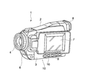
図1は本発明の一実施形態に係る携帯型電子機器の構成を示す要部分解斜視図、図2はその携帯型電子機器のマイクロフォン及びレンズを含めた断面図、図3はその電子機器の外観図である。ここでは、携帯型電子機器として、携帯型ビデオカメラを例に取っているが、勿論携帯電話やその他の電子機器であっても勿論構わない。
Hereinafter, embodiments of the present invention will be described with reference to the drawings.
FIG. 1 is an exploded perspective view of a main part showing a configuration of a portable electronic device according to an embodiment of the present invention, FIG. 2 is a sectional view including a microphone and a lens of the portable electronic device, and FIG. It is an external view. Here, a portable video camera is taken as an example of the portable electronic device, but a portable phone or other electronic device may of course be used.
これらの図に示すように、携帯型ビデオカメラ1では、撮像した被写体映像はカメラ本体2の筐体3内に搭載されたHDDユニット5によってビデオ記録・再生などが行われる。
As shown in these drawings, in the
ここで、図3において、4はカメラ部のレンズ、6は撮像時の集音用のマイクロフォン、7はカメラ本体2に回転可能に枢着されたモニタ兼ファインダとなるLCDなどの表示部、8は接眼部、9は操作釦群であり、筐体3の底部10には冷却装置16が配置されている。
Here, in FIG. 3, 4 is a lens of the camera unit, 6 is a microphone for collecting sound during imaging, 7 is a display unit such as an LCD which is a monitor and finder pivotally attached to the
HDDユニット5のケーシング5aは表側(図1では裏側)がアルミダイカスト等で鋳造した金属部であり、裏側(図1では表側)は駆動用プリント基板で構成されているものが多いので表側の金属部分を下側にして熱伝導シート21aを介して、熱伝導率の高い、例えば銅等の金属から成る熱伝達部20に接合される。
The
熱伝達部20は帯状銅板の両端を互に反対方向に折り曲げた形状とし、一方の折曲片20aに熱伝達シート21aを接合し、HDDユニット5に固定する。他方の折曲片20bにも、熱伝達シート21bを接合し、該熱伝導シート21bを密閉ケーシング19の上面に接合して、図2に示すようにHDDユニット5を密閉ケーシング19上に固定させる。
The
密閉ケーシング19及び冷却装置16はビス23を介して筐体3の底部10に固定される。従って、HDDユニット5で高温度に温められた熱は熱伝達部20に伝達され、この熱が冷却装置16により冷却される。
The sealed
図4は冷却装置16の構成を示す断面図である。
図4に示すように、冷却装置16は、外部から気体を導入するために筐体3の底部10(気体導入部)の例えば4箇所に設けられた流路31(導入孔25)と、各流路31を介して外部から気体を導入し、内部から気体を噴出する圧電ポンプ32と、各流路31を塞ぐように設けられ、気体は通過するが液体の通過を規制するフィルタ33とを具備する。
FIG. 4 is a cross-sectional view showing the configuration of the
As shown in FIG. 4, the
図5は圧電ポンプ32の分解斜視図である。
図4及び図5に示すように、圧電ポンプ32は、上から順番に、壁体としての天板34、流路(通路)31を形成するめの介挿板35、ポンプ室36の天板37、ポンプ室36内の空間を形成するための介挿板38、ダイヤフラム39、ダイヤフラム39の裏面に取り付けられた圧電素子40、及び保護リング41から構成される。
FIG. 5 is an exploded perspective view of the
As shown in FIGS. 4 and 5, the
天板34は、例えば略箱形状であり、この天板34の中央に圧電ポンプ32から噴出された気体を折曲片20b側に向けて吐出するための吐出口42が設けられている。
The
介挿板35は、例えば略矩形状であり、流路31を形成するために十字状の打ち抜き部43を有する。ベンチュリーノズル部は上記の吐出口42に対応した位置、つまり介挿板35の中央(十字状の打ち抜き部43の交差部)に設けられている。
The
ポンプ室36の天板37は、例えば正方形の各角部が切り取られた例えば8角形の形状をなしている。これらの正方形の各角部が切り取られた部分44は、天板34の内壁との間で流路31を形成する。天板37は、流路31からポンプ室36内に気体を導入すると共に、ポンプ室36内から吐出口42を介して折曲片20b側に気体を噴出するための孔45が設けられている。
The
ポンプ室36内の空間を形成するための介挿板38も、上記の天板37と同様の形状をなし、切り取られた部分46は、天板34の内壁の間で流路31を形成する。介挿板38は、ポンプ室36としてのある程度空間を形成するための厚さを有する。
The
ダイヤフラム39も、上記の天板37と同様の形状をなし、切り取られた部分47は、天板34の内壁との間で流路31を形成する。1辺から水平方向に突起した突起部48は、圧電素子40への配線パターンが形成される。
The
圧電素子40は、例えば円形をなし、印加された電圧(交番電圧)に応じて振動する。図6はこの圧電素子40の制御系の概略構成を示すブロック図であり、制御部49が例えば筐体3内の温度検出センサ50により検出された温度に応じた電圧値の電圧を圧電素子40に印加するように電源供給部51を制御している。印加する電圧の周波数としては、例えば非可聴音領域である22kHz以上であることが騒音抑制の観点から好ましい。
The
保護リング41は、上記の天板37などと同様の形状をなし、切り取られた部分52は、天板34の内壁との間で流路31を形成する。保護リング41は圧電素子40の振動によってダイヤフラム39及び圧電素子40が振動の際に筐体3の底部10にぶつかることを防止する程度の厚さを有する。
The
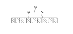
図7はフィルタ33の断面図である。
フィルタ33は、図7に示すように、例えばテフロン(登録商標)などの撥水性の高いシート状素材53に多数の微細な孔54が穿設された防水通気シートである。微細な孔54としては、例えば円形で、直径250μm以下、より好ましくは150μm以下であればよい。なお、フィルタ33として、ゴアテックス(登録商標)などからなる防水通気シートを用いても勿論構わない。
FIG. 7 is a sectional view of the
As shown in FIG. 7, the
フィルタ33として上記の防水通気シートとすると、水滴はシート状素材53の撥水性と水自身の表面張力の影響で玉状になり、シートを通過することができない。一方、空気は微細な孔54を自由に通過できるため、水は通さず空気は通すという機能が得られる。フィルタ33として撥水性の高いシート状素材53に多数の微細な孔54が穿設された防水通気シートを用いることで、通気抵抗や防水性を最適に設計することが可能である。例えば、吸入圧力が高い場合は孔径を小さくして水を吸入してしまうことを防ぎ、圧力が低い場合は孔径を大きくして通気抵抗を小さくする、などの設計が可能である。
When the above-described waterproof breathable sheet is used as the
上記の微細な孔54として150μm以下程度では、防水通気シート全面を水で覆い尽くさない限り、圧電ポンプ32の吸引圧力(静圧と考えても良い)が2kPa程度と高くてもまず水滴が防水通気シートを通過することはない。なぜならば、水滴が付着していない部分から空気が通過して圧力を逃がしてしまうからである。一方、微細な孔54として直径250μm以下程度では、圧電ポンプ32の吸引圧力が300Pa以下のように低い場合に限って使用できる。大きい孔径では、防水通気シートの通気抵抗が低いため、吸引圧力の低い圧電ポンプ32を使用した際の性能低下が少なくてすむ。
If the fine holes 54 are about 150 μm or less, water droplets are waterproof at first even if the suction pressure of the piezoelectric pump 32 (which may be considered as static pressure) is as high as about 2 kPa unless the entire waterproof ventilation sheet is covered with water. It does not pass through the ventilation sheet. This is because air passes through a portion where water droplets are not attached and releases pressure. On the other hand, when the diameter of the
次に、このように構成された冷却装置16の動作を図8(a)〜(e)に基づき説明する。
Next, operation | movement of the
図8(a)〜図(e)は、冷却装置16の動作を説明するための図である。
FIG. 8A to FIG. 8E are diagrams for explaining the operation of the
図8(a)に示す状態において、圧電素子40に交番電圧を印加することにより、図8(b)に示すようにダイヤフラム39を屈曲変形させ、ポンプ室36の容積を増加させる。これにより、外気を導入孔25から流路31内に導入し孔45を介してポンプ室36内に取り入れる。
In the state shown in FIG. 8A, by applying an alternating voltage to the
図8(c)及び図8(d)に示すようにダイヤフラム39を屈曲変形させ、ポンプ室36の容積を減少させる。これにより、孔45を介してポンプ室36内の空気を吐出口42から噴出させる。このとき、孔45及び吐出口42により構成されたベンチュリーノズルにより、流路(通路)31内の空気を同時に吐出口42から噴出し、流量の増大を図っている。この結果、図2に示す密閉ケーシング19に空気を噴き付けて、熱伝達部20を介してHDDユニット5を冷却する。
As shown in FIGS. 8C and 8D, the
図8(e)に示すようにダイヤフラム39を屈曲変形させ、再びポンプ室36の容積を増加させる。これにより、流路31を介して再び外気を孔45からポンプ室36内に取り入れる。
As shown in FIG. 8E, the
図8では、孔45と吐出口42とが別れているものを図示している。しかし、1個の連続した孔部で構成するようにしてもよい。
In FIG. 8, the
このように本実施形態によれば、冷却装置16の流路(通路)31に、流路31を塞ぐように気体は通過するが液体の通過を規制するフィルタ33を設けたので、水滴などを吸い込むようなことはなくなり、防水性に優れた携帯型ビデオカメラ1を得ることができる。また、圧電ポンプ32は静圧が2kPa程度と高いため、フィルタ33によって圧電ポンプ32による吸引力が実質的に低下することは小さく、従って冷却を効率的に行うことができる。
As described above, according to the present embodiment, the flow path (passage) 31 of the
フィルタ33を設けたことで、例えば冷却装置16が搭載される携帯型ビデオカメラ1内に埃などが吸引される機会が激減し、このような埃などに起因する携帯型ビデオカメラ1の故障が非常に少なくなる。また、圧電ポンプ32を用いたことで、静粛性に優れ、しかも低消費電力化が実現できる。しかも、圧電ポンプ32は薄型化が容易に可能であることから、例えば携帯型ビデオカメラ1の小型薄型化に寄与することが十分可能である。
By providing the
圧電ポンプ32は、流路(通路)31から気体を内部に導入し、かつ、内部から気体を噴出するための共通の孔45を有し、圧電素子40によって駆動されるポンプ室36と、流路(通路)31を挟んで孔45と対向するように設けられた吐出口42を有する天板34とを備えている。このような共通の孔45及び吐出口42によりベンチュリーノズルを構成することで、圧電ポンプの「呼吸動作」による流量の増大を図ることができる。
The
なお、ダイヤフラム39は、携帯型ビデオカメラ1のスピーカとして兼用されるようにしてもよいこれにより、低コスト化及び小型薄型化を図ることができる。
The
次に、冷却装置1の一実施例について説明する。
(1)ポンプ室36の容積(面積、高さ)
直径 φ16mm
高さ 0.15mm
(2)外部からの空気導入孔の面積
直径 φ1.2mm×4箇所
(3)空気の導出口の面積(吐出口42、孔45)
ポンプ室の孔45 直径 φ0.6mm
吐出口42 直径 φ0.8mm
(4)冷却装置16全体の容積(面積、高さ)
面積 20mm×20mm
高さ 1.6mm
(ノズルを除いた高さ。ノズルを設ける場合のノズル高さは0.8mmであり、全高は2.4mm)
(5)圧電素子40の振幅
±6μm程度
(6)圧電素子40の振動周波数
24kHz程度
(7)フィルタ33の物質名と孔径と孔の密度と厚さ
サンマップLC−T(日東電工製の超高分子量ポリエチレン多孔質フィルムの商品名)
平均孔径 17μm
気孔率 25%
厚さ 0.1mm
通気度 1.4sec/100cm2
(8)フィルタ33のインピーダンス
0.9kPa/(L/min)程度
(φ16mmの領域で使用した場合、通気度1.4sec/100cm2から換算した値)
(9)静圧
2kPa
(10)流量
1.0L/minである。
Next, an example of the
(1) Volume (area, height) of the
Diameter φ16mm
Height 0.15mm
(2) Area of air introduction hole from outside Diameter φ1.2 mm × 4 locations (3) Area of air outlet (discharge
(4) Volume (area, height) of the
Area 20mm x 20mm
1.6mm height
(The height excluding the nozzle. The nozzle height when the nozzle is provided is 0.8 mm, and the total height is 2.4 mm.)
(5) The amplitude of the
Average pore size 17μm
Thickness 0.1mm
Air permeability 1.4sec / 100cm2
(8) Impedance of
(9) Static pressure 2kPa
(10) The flow rate is 1.0 L / min.
図9は圧電ポンプ32の動作特性を示す図、図10は圧電ポンプ32と軸流ファンとの動作特性を比較する図である。
FIG. 9 is a diagram showing operating characteristics of the
これらの図は圧電ポンプ32の静圧が1.2kPa、最大流量20cc/sであり、軸流ファン(市販品)の静圧が0.04kPa、最大流量2500cc/sである場合を示している。
These figures show the case where the static pressure of the
圧電ポンプ32の動作点が10cc/s以上であるのに対し、軸流ファン(市販品)が1cc/s以下であることを示している。
It shows that the operating point of the
防水通気フィルタ(シート)の通気度は1.4sec/100cm3であり、これはガーレー法による測定(6.42cm2の面積に対して、1.23kPaの差圧を加えた時に、空気100cc3の通過時間を測定)において得られた値である。 The air permeability of the waterproof breathable filter (sheet) is 1.4 sec / 100 cm3, which is measured by the Gurley method (passing time of 100 cc3 of air when a differential pressure of 1.23 kPa is applied to an area of 6.42 cm2. Is a value obtained in (Measurement).
通気抵抗が小さい(すなわち筐体3中を空気が自在に流れる状態→実際は困難)場合は軸流ファン(ファンモーター)の方が流量を多く得ることが可能であるが、フィルタ33(防水通気フィルタ(シート))を使用する場合(または筐体3内を空気が非常に流れにくい状態)では、軸流ファンでは全く流量を得ることができず、圧電ポンプ32(ブロア)でなければ冷却効果を得ることができない。
When the airflow resistance is small (that is, when the air flows freely through the
本発明の他の実施形態に係る冷却装置1´について説明する。本実施形態以降においては、上記実施形態と同一の構成等には同一の符号を付しその説明を省略し、異なる箇所を中心に説明する。 A cooling device 1 'according to another embodiment of the present invention will be described. In this embodiment and subsequent embodiments, the same components as those in the above-described embodiment will be denoted by the same reference numerals, description thereof will be omitted, and different points will be mainly described.
図11は他の実施形態の冷却装置が設置された携帯型電子機器の部分断面図である。
図11に示すように、フィルタ33とは異なる位置に設けられたフィルタ33´を有する冷却装置16´を備えている。
FIG. 11 is a partial cross-sectional view of a portable electronic device in which a cooling device according to another embodiment is installed.
As shown in FIG. 11, a
フィルタ33´は、フィルタ33と同一の構成部材で構成され、密閉ケーシング19の面積とほぼ同じ面積に亘って筐体3の内面上に設けられている。フィルタ33´は、筐体3の気体の導入口17、排出口18を塞ぐように設けられている。冷却装置16´の導入孔25は(図4参照)、導入口17に対応している。
The
このような構成によれば、冷却装置16´の圧電素子40を駆動することで、導入口17から矢印方向に外気を密閉ケーシング19内に取り込み、排出口18を介して気体を外部に排出するときに、フィルタ33´により筐体3内に水滴などを吸い込んだり、排出口18から水滴が流入したりすることを防止することができる。
According to such a configuration, by driving the
フィルタ33´は、密閉ケーシング19の面積とほぼ同じ面積に亘って筐体3の内面上に設けられていので、冷却装置16´の防振性を向上させることができる。フィルタ33´は密閉ケーシング19の面積とほぼ同じ面積に亘って筐体3の内面上に設けられているので、確実かつ容易に導入口17及び排出口18を塞ぐことができる。
Since the
図12は他の実施形態の冷却装置が設置された携帯型電子機器の部分断面図である。
本実施形態では、図11に比べて、筐体3の外部表面3Aに対して凹部55を有し、凹部55の底部に流路31の導入口17が設けられている点が異なる。このような構成では、流路31の気体の導入口17が水によって塞がれて気体の導入口17を介して外部から水を吸い込むようなことがなくなる。
FIG. 12 is a partial cross-sectional view of a portable electronic device in which a cooling device according to another embodiment is installed.
This embodiment is different from FIG. 11 in that the
図13は他の実施形態の冷却装置が設置された携帯型電子機器の部分断面図である。
図13に示すように、CCD14に空気を噴出する冷却装置16と、冷却装置16に気体を導入する導入部60と、導入部60内に水滴などが流入することを防止するフィルタ33とを備えている。
FIG. 13 is a partial cross-sectional view of a portable electronic device in which a cooling device according to another embodiment is installed.
As shown in FIG. 13, a
冷却装置16は、その吐出孔42からCCD14に気体を噴出することができるように導入部60に設けられている。
The
導入部60は、外部から冷却装置16の流路31の導入孔に気体を案内する流路61と、冷却装置16の流路31の導入孔に連通する連通孔62と、流路61内に外気を導入するために筐体3に形成された開口部63とを備えている。
The
フィルタ33は、導入部60の流路61の開口部63を塞ぐように設けられている。
The
このような構成によれば、CCD14等を直接的に冷却することができ、このときに、フィルタ33により外部から水滴が流入することを防止することができる。
According to such a configuration, the
図14は他の実施形態の冷却装置が設置された携帯型電子機器の部分断面図である。
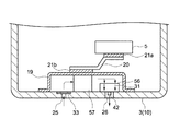
熱伝達シート21bに対応する位置に熱交換部57と、熱交換部57の隣に密閉ケーシング19内の空気を外部に排出する冷却装置56とを備えている。
FIG. 14 is a partial cross-sectional view of a portable electronic device in which a cooling device according to another embodiment is installed.
A
熱交換部57は、導入孔25からフィルタ33を介して密閉ケーシング19内に導入され熱伝達シート21bを冷却する後述するヒートシンクなどである。
The
冷却装置56は、吐出口42(図4参照)側を筐体3側に向けて、筐体3に配置されている。吐出口42から吐出される空気が外部に噴出されるように、吐出口42と筐体3の噴出孔26とが位置合わせされている。噴出孔26内にフィルタ33を挿入するようにしてもよい。
The
このような構成によれば、冷却装置56を駆動することで、導入孔25からフィルタ33を介して外気を密閉ケーシング19内に導入すると共に、密閉ケーシング19内の空気を吐出口42を介して噴出孔26から外部へ噴出することができる。このとき、密閉ケーシング19内で、矢印方向に気体の流れが発生し、HDDユニット5の熱を熱伝達部20等を介して熱交換部57で奪い、HDDユニット5を冷却することができる。つまり、冷却装置56から吐出される空気を直接密閉ケーシング19に噴き付けずに、熱交換部57を用いてHDDユニット5を冷却することができる。
According to such a configuration, by driving the
図15は熱交換部57(57a〜57e)の例を示す断面図である。
図15(a)に示すように、熱交換部57aは、断面が櫛歯形状を有するヒートシンク58aと、ヒートシンク58aを被覆するカバー59とを備えている。ヒートシンク58aは、例えば導入孔25側から噴出孔26側に気体が凹部を通過するように設けられている。
FIG. 15 is a cross-sectional view showing an example of the heat exchange section 57 (57a to 57e).
As shown in FIG. 15A, the
図15(b)に示すように、熱交換部57bは、断面が蛇行形状を有するヒートシンク58bと、ヒートシンク58bを被覆するカバー59とを備えている。
As shown in FIG. 15B, the
図15(c)に示すように、熱交換部57cは、断面が凹凸形状を有するヒートシンク58cと、ヒートシンク58cを被覆するカバー59とを備えている。
As shown in FIG. 15C, the
図15(d)に示すように、熱交換部57dは、断面が蛇腹形状を有するヒートシンク58dと、ヒートシンク58dを被覆するカバー59とを備えている。
As shown in FIG. 15D, the
図15(e)に示すように、熱交換部57eは、断面複数の貫通孔58gを有するヒートシンク58eと、ヒートシンク58eを被覆するカバー59とを備えている。貫通孔58は、例えば導入孔25側から噴出孔26側に気体が通過するように形成されている。
As shown in FIG. 15E, the
これらの図に示すように、ヒートシンク58a〜58eは、例えばアルミニウム等の金属で構成されている。
As shown in these drawings, the
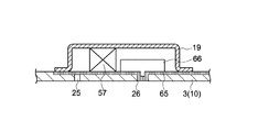
図16は他の実施形態の冷却装置が設置された携帯型電子機器の部分断面図である。
図16に示す冷却装置66は、図14に示す冷却装置56に比べて、フィルタ65が配置されている位置が異なる。
FIG. 16 is a partial cross-sectional view of a portable electronic device in which a cooling device according to another embodiment is installed.
The
フィルタ65は、密閉ケーシング19とほぼ同様の実装面積を覆うように筐体3の内面上に配置されている。フィルタ65は、導入孔25、噴出孔26を塞ぐように配置されている。フィルタ65は、フィルタ33と同様の構成材料が用いられている。
The
このような構成によれば、HDDユニット5等の熱を放熱すると共に、導入孔25、噴出孔26から水滴が密閉ケーシング19内に流入することを防止することができる。
According to such a configuration, heat from the
密閉ケーシング19及び筐体3が共に金属製である場合には、フィルタ65によりある程度断熱されているため、筐体3に直接熱が伝わりにくく、筐体3が熱くなりにくい。
When both the sealed
密閉ケーシング19が金属製であり、筐体3が樹脂製である場合、密閉ケーシング19が熱くなっても、筐体3が樹脂製であり熱が伝わりにくい。
When the sealed
図17は他の実施形態の冷却装置が設置された携帯型電子機器の部分断面図である。
本実施形態は、図14において密閉ケーシング19が樹脂製である場合の例である。
図17に示すように、図14に比べて、挿入孔19aが形成された密閉ケーシング19´と、熱伝達シート21bを介して熱伝達部20に接続された熱交換部57´とを備えている。
FIG. 17 is a partial cross-sectional view of a portable electronic device in which a cooling device according to another embodiment is installed.
This embodiment is an example in which the sealed
As shown in FIG. 17, compared with FIG. 14, a sealed
密閉ケーシング19´は、挿入孔19aが形成され、挿入孔19a内に熱交換部57´の頂部が挿入されている。熱交換部57´の頂部は、熱伝達シート21bを介さずに熱伝達部20に接続されている。
The sealed
このような構成によれば、密閉ケーシング19´が樹脂製であっても、熱伝達シート21bを介して熱交換部57´によりHDDユニット5の熱を筐体3の外部に放熱することができる。このとき、熱交換部57´により放熱されるため、熱が筐体3に伝わりにくい。従って、筐体3は樹脂製であっても金属製であってもよい。
According to such a configuration, even if the sealed
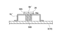
図18は図17の熱交換部の一例を示す断面図である。 FIG. 18 is a cross-sectional view showing an example of the heat exchange section of FIG.
図18に示すように、熱交換部57´は、熱伝達部20に接続されたヒートシンク58´と、ヒートシンク58´を支持し収容する密閉ケーシング19´とを備えている。
As shown in FIG. 18, the
ヒートシンク58´は、熱伝達部20に接続される接続部58Aと、略櫛歯形状をなす凸部58Bと有しており、接続部58Aは密閉ケーシング19´に支持されている。凸部58Bの間の凹部を通過する気体が導入孔25から噴出孔26に向かうように複数の凸部58Bが配列している。
The heat sink 58 'has a
このような構成によれば、熱伝達部20の熱をヒートシンク58´の接続部58Aを介して凸部58Bから放熱し、HDDユニット5を効率的に冷却することができる。
According to such a configuration, the heat of the
図19は別の冷却装置が配置された携帯型電子機器の構成を示す断面図である。
図19に示すように、冷却装置16Aは、外部から気体を導入するために筐体3の底部10(気体導入部)の例えば2箇所に設けられた導入孔25と、各流路31を介して外部から気体を導入し、内部から気体を噴出する圧電ポンプ32´と、各流路31を塞ぐように設けられ、気体は通過するが液体の通過を規制するフィルタ33Aとを具備する。
FIG. 19 is a cross-sectional view illustrating a configuration of a portable electronic device in which another cooling device is arranged.
As shown in FIG. 19, the
図20は図19に示す圧電ポンプ32´の分解斜視図である。
図19及び図20に示すように、圧電ポンプ32´は、上から順番に、壁体としての天板34´、流路(通路)31を形成するめの介挿板35´、ポンプ室36´の天板37´、ポンプ室36´内の空間を形成するための介挿板38´、ダイヤフラム39´、ダイヤフラム39´の裏面に取り付けられた圧電素子40、及び保護リング41´から構成される。
20 is an exploded perspective view of the piezoelectric pump 32 'shown in FIG.
As shown in FIGS. 19 and 20, the
介挿板35´は、例えば矩形枠形状である。ベンチュリーノズル部は上記の吐出口42に対応した位置、つまり介挿板35´の中央(枠の孔の交差部)に設けられている。
The
ポンプ室36´の天板37´は、例えば正方形の対向する一対の角部が切り取られた例えば6角形の形状をなしている。これらの正方形の2つの角部が切り取られた部分44は、天板34´の内壁との間で流路31を形成する。
The
ポンプ室36´内の空間を形成するための介挿板38´も、上記の天板37´と同様の形状をなしている。
An
ダイヤフラム39´も、上記の天板37´と同様の形状をなし、切り取られた部分47は、天板34´の内壁との間で流路31を形成する。
The
保護リング41´は、切断部41Aが形成されている。
The protection ring 41 'is formed with a cutting
フィルタ33Aは、筐体3上に設けられた凸部68の上に筐体3から離間するように、冷却装置16Aの実装面積とほぼ同じ実装面積になるように設けられている。フィルタ33Aは、上述したように例えばテフロン(登録商標)などの撥水性の高いシート状素材53に多数の微細な孔54が穿設された防水通気シートである。なお、フィルタ33Aとして、ゴアテックス(登録商標)などからなる防水通気シートを用いても勿論構わない。
The
図19に示すように、圧電素子40を駆動しポンプ室36´内の空間が大きくなるときに、外部の空気が導入孔25から流路31に導入され、孔45を介してポンプ室36´内の空間に流入する。このとき、導入孔25から導入された空気は、矢印で示すように冷却装置16Aの実装面積と同じ面積のフィルタ33Aを介して保護リング41´側に流入し切断部41Aを介して流路31に流入する。圧電素子40を駆動しポンプ室36´内の空間が小さくなるときに、ポンプ室36´内の空間に流入している空気を吐出口42を介して天板34´の外部に噴出する。
As shown in FIG. 19, when the
このような構成によれば、導入孔25から導入された空気は、図19の矢印で示すように冷却装置16Aの実装面積と同じ面積のフィルタ33Aを介して保護リング41´側に流入し切断部41Aを介して流路31に流入する。従って、効率良く空気を導入することができる。
According to such a configuration, the air introduced from the
圧電ポンプ32´の実装面積すべてをフィルタ33Aに利用できるので、フィルタ33Aの通気抵抗を減少させて、冷却装置16Aの性能低下を防止することができる。圧電ポンプ32´は、圧電素子40が駆動するための空間を備えるため、この空間の面積をフィルタ33Aで使用できる構成とすることで、圧電ポンプ32´の面積で実現できる最大の性能を発揮することができる。
Since the entire mounting area of the
図21は別の冷却装置が配置された携帯型電子機器の構成を示す断面図である。
図21に示すように、冷却装置16Bは、外部から気体を導入するために筐体3の底部10(気体導入部)に設けられた導入孔25と、導入孔25を介して外部から気体を導入し、内部から気体を噴出する圧電ポンプ32Aと、導入孔25、流路31を塞ぐように設けられ、気体は通過するが液体の通過を規制するフィルタ33とを具備する。
FIG. 21 is a cross-sectional view showing a configuration of a portable electronic device in which another cooling device is arranged.
As shown in FIG. 21, the
図22は図21に示す圧電ポンプ32Aの分解斜視図である。
図21及び図22に示すように、圧電ポンプ32Aは、上から順番に、壁体としての天板34´、流路(通路)31を形成するめの介挿板35A、ポンプ室36Aの天板37A、ポンプ室36A内の空間を形成するための介挿板38A、ダイヤフラム39´、ダイヤフラム39´の裏面に取り付けられた圧電素子40、及び保護リング41Bから構成される。
FIG. 22 is an exploded perspective view of the
As shown in FIGS. 21 and 22, the
介挿板35Aは、例えば略矩形板形状であり、流路31を形成するために角部に孔35bが形成され、中央に孔35aが形成され、孔35aと孔35bとは直線状の孔35cにより?がっている。この孔35bは、流路31を形成する。ベンチュリーノズル部は上記の吐出口42に対応した位置、つまり介挿板35の中央に設けられている。
The
ポンプ室36Aの天板37Aは、例えば四角形の形状をなしている。孔35bに対応する位置に孔37Bが形成されている。この孔37Bは、流路31を形成する。天板37Aは、流路31からポンプ室36A内に気体を導入すると共に、ポンプ室36A内から吐出口42を介して折曲片20b側に気体を噴出するための孔45が設けられている。
The
ポンプ室36A内の空間を形成するための介挿板38Aも、上記の天板37Aと同様の形状をなしている。天板37Aには、孔37Bに対応する位置に孔38Bが形成されている。孔38Bにより、流路31が形成されている。介挿板38Aは、ポンプ室36Aとしてのある程度空間を形成するための厚さを有する。
An
保護リング41Bは、上記の介挿板38Aなどと同様の形状をなし、3つの切り取られた部分52、切断部41Cは、天板34´の内壁との間で流路31を形成する。保護リング41Bは圧電素子40の振動によってダイヤフラム39´及び圧電素子40が振動の際に筐体3の底部10にぶつかることを防止する程度の厚さを有する。
The
このような構成によれば、圧電素子40の駆動により、導入孔25から外気を流路31に取り込み、孔35b、直線状の孔35c、孔35a及び孔45を介してポンプ室36A内に空気を取り込むことができる。このとき、フィルタ33により水滴などが筐体3内に進入することを防止することができる。
According to such a configuration, by driving the
図23は別の冷却装置を備えた携帯型電子機器の構成を示す断面図である。
図23に示すように、携帯型ビデオカメラ1´は、図21に示す冷却装置16Bの代わりに、フィルタ33Bを備えた冷却装置16Cを備えている。
FIG. 23 is a cross-sectional view illustrating a configuration of a portable electronic device including another cooling device.
As shown in FIG. 23, the
冷却装置16Cのフィルタ33Bは、天板34Cとほぼ同様の実装面積を覆うように筐体3の内面上に配置されている。フィルタ33Bは、導入孔25を塞ぐように配置されている。フィルタ33Bは、フィルタ33と同様の構成材料が用いられている。フィルタ33B上に冷却装置66が配置されている。天板34´は、フランジ部34Fを有しており、フランジ部34Fが複数箇所でネジ留めされている。
The
このような構成によれば、フィルタ33Bにより防振効果を得ることができる。なお、フィルタ33Bの他に更に別の防振シートをフィルタ33Bと筐体3との間に配置するようにしてもよい。この場合には、導入孔25に対応する位置に開口を形成すればよい。
According to such a configuration, an anti-vibration effect can be obtained by the
図24は別の冷却装置を備えた携帯型電子機器の構成を示す断面図である。
図24に示すように、携帯型ビデオカメラ1Bは、図23に示す冷却装置16Cの代わりに、フィルタ33Cを備えた冷却装置16Dを備えている。冷却装置16Dのフィルタ33Cは、天板34Dとほぼ同様の実装面積を覆うように筐体3の内面上に配置されている。フィルタ33Cは、導入孔25を塞ぐように配置されている。
FIG. 24 is a cross-sectional view illustrating a configuration of a portable electronic device including another cooling device.
As shown in FIG. 24, the
筐体3の内面側には、爪部82が形成されており、天板34Dの一端部、フィルタ33Cの一端部及び防振シート81が爪部82により挟持されている。天板34Dの他端部は、フィルタ33Cの他端部を介して、筐体3にネジ留めされている。
A
このような構成によれば、フィルタ33Cにより、冷却装置16D内に水滴などが進入することを防止し、フィルタ33C及び防振シート81による防振効果を得ることができる。また、爪部82により冷却装置16Dの流路31と、筐体3の導入孔25との位置合わせを容易に行うことができる。また、ネジなどの部品点数を削減し低コスト化を図ることができる。
According to such a configuration, it is possible to prevent water droplets or the like from entering the
図25は別の冷却装置を備えた携帯型電子機器の構成を示す断面図である。
図25に示すように、携帯型ビデオカメラ1Cは、冷却装置ユニット16Uを備えている。
FIG. 25 is a cross-sectional view illustrating a configuration of a portable electronic device including another cooling device.
As shown in FIG. 25, the
冷却装置ユニット16Uは、筐体3に例えばネジなどにより着脱自在に構成されている。冷却装置ユニット16Uは、図23に示す冷却装置16Cと、爪部85を備える基板86とを備えている。
The
冷却装置16Cの天板34´のフランジ部34F及びフィルタ33Bの両端部がそれぞれ爪部85に挟持されている。
The
このような構成によれば、冷却装置ユニット16Uを筐体3から取り外し、冷却装置16Cや携帯型ビデオカメラ1C内を容易にメンテナンスすることができる。
According to such a configuration, the
なお、本発明は以上説明した実施の形態には限定されるものではなく、本発明の技術思想の範囲内で種々の変形が可能である。 The present invention is not limited to the embodiments described above, and various modifications can be made within the scope of the technical idea of the present invention.
1,1´,1B,1C 携帯型ビデオカメラ
3 筐体
3A 外部表面
10 底部
16,16A,16B,16C,16D,56,66 冷却装置
25 導入孔
31 通路
32 圧電ポンプ
33,33´,33B,33C フィルタ
34 天板
36 ポンプ室
40 圧電素子
42 吐出口
45 孔
55 凹部
25 導入孔
17 噴出孔
53 シート状素材
54 孔
57,57a,57b,57c,57d,57e 熱交換部
1, 1 ', 1B, 1C
Claims (11)
前記通路を介して外部から気体を導入し、内部から気体を噴出する圧電ポンプと、
前記通路を塞ぐように設けられ、少なくとも気体は通過するが液体の通過を規制するフィルタと
を具備する冷却装置。 A gas introduction part having a passage for introducing gas from the outside;
A piezoelectric pump that introduces gas from the outside through the passage and ejects the gas from the inside;
A cooling device comprising: a filter provided so as to close the passage, wherein at least gas passes but restricts passage of liquid.
前記圧電ポンプは、
前記通路から気体を内部に導入し、かつ、内部から気体を噴出するための共通の孔を有し、圧電体によって駆動されるポンプ室と、
前記通路を挟んで前記孔と対向するように設けられた吐出口を有する壁体と
を具備する冷却装置。 The cooling device according to claim 1,
The piezoelectric pump is
A pump chamber that introduces gas from the passage into the interior and has a common hole for ejecting the gas from the interior, and is driven by a piezoelectric body;
And a wall body having a discharge port provided so as to face the hole with the passage interposed therebetween.
前記気体導入部は、外部表面に対して凹部を有し、
前記凹部の底部に前記通路の導入口が設けられている
冷却装置。 The cooling device according to claim 1,
The gas introduction part has a recess with respect to the external surface;
A cooling device in which an inlet for the passage is provided at the bottom of the recess.
前記圧電ポンプは、前記通路から気体を内部に導入するための導入孔と、内部から外部に気体を噴出するための噴出孔とを有し、圧電体によって駆動されるポンプ室を具備し、
前記冷却装置は、前記通路上に配置された熱交換体を更に具備する冷却装置。 The cooling device according to claim 1,
The piezoelectric pump has an introduction hole for introducing gas into the inside from the passage and an ejection hole for ejecting gas from the inside to the outside, and includes a pump chamber driven by a piezoelectric body,
The cooling device further includes a heat exchanger disposed on the passage.
前記圧電ポンプは、22kHz以上の周波数で駆動する冷却装置。 The cooling device according to claim 1,
The piezoelectric pump is a cooling device that is driven at a frequency of 22 kHz or more.
前記フィルタは、撥水性の高いシート状素材に多数の微細な孔が穿設された防水通気シートである冷却装置。 The cooling device according to claim 1,
The cooling device is a cooling air-permeable sheet in which a large number of fine holes are formed in a highly water-repellent sheet material.
前記通路を挟んで前記孔と対向するように設けられた吐出口を有し、前記ポンプ室との間で前記通路を構成する壁体と
を具備する圧電ポンプ。 A pump chamber driven by a piezoelectric body, having a common hole for introducing gas into the inside from a passage for introducing gas from outside and ejecting gas from the inside;
A piezoelectric pump comprising: a discharge port provided so as to face the hole across the passage, and a wall constituting the passage with the pump chamber.
前記ポンプ室は、
前記圧電体が取り付けられたダイヤフラムと、
前記ダイヤフラムとの間でポンプ室内を形成し、前記ダイヤフラムと対面する側に前記孔が設けられたポンプ本体と
を具備する圧電ポンプ。 The piezoelectric pump according to claim 7,
The pump chamber is
A diaphragm to which the piezoelectric body is attached;
A piezoelectric pump comprising: a pump body which forms a pump chamber with the diaphragm and has the hole provided on a side facing the diaphragm.
前記吐出口の径は、前記孔の径よりも大きい圧電ポンプ。 The piezoelectric pump according to claim 7,
A piezoelectric pump in which a diameter of the discharge port is larger than a diameter of the hole.
前記圧電ポンプから噴出された気体に基づいて冷却される電子部品と
を具備する電子機器。 A gas introduction section having a passage for introducing gas from outside, a piezoelectric pump for introducing gas from outside through the passage, ejecting gas from inside, and driving at a frequency outside the audible sound range; and the passage A cooling device having a filter that is provided so as to be closed and at least allows gas to pass but restricts passage of liquid;
An electronic device comprising: an electronic component that is cooled based on gas ejected from the piezoelectric pump.
前記圧電ポンプは、
前記圧電体が取り付けられたダイヤフラムと、前記ダイヤフラムとの間でポンプ室内を形成し、前記ダイヤフラムと対面する側に前記孔が設けられたポンプ本体とを有するポンプ室を具備し、
前記ダイヤフラムは、前記電子機器のスピーカとして兼用される
電子機器。 The electronic device according to claim 10,
The piezoelectric pump is
A pump chamber having a pump body formed between the diaphragm to which the piezoelectric body is attached and the diaphragm, and a pump body provided with the hole on the side facing the diaphragm;
The diaphragm is an electronic device that is also used as a speaker of the electronic device.
Priority Applications (1)
| Application Number | Priority Date | Filing Date | Title |
|---|---|---|---|
| JP2007278203A JP2009103111A (en) | 2007-10-25 | 2007-10-25 | Cooling system and electronic equipment |
Applications Claiming Priority (1)
| Application Number | Priority Date | Filing Date | Title |
|---|---|---|---|
| JP2007278203A JP2009103111A (en) | 2007-10-25 | 2007-10-25 | Cooling system and electronic equipment |
Publications (1)
| Publication Number | Publication Date |
|---|---|
| JP2009103111A true JP2009103111A (en) | 2009-05-14 |
Family
ID=40705028
Family Applications (1)
| Application Number | Title | Priority Date | Filing Date |
|---|---|---|---|
| JP2007278203A Pending JP2009103111A (en) | 2007-10-25 | 2007-10-25 | Cooling system and electronic equipment |
Country Status (1)
| Country | Link |
|---|---|
| JP (1) | JP2009103111A (en) |
Cited By (18)
| Publication number | Priority date | Publication date | Assignee | Title |
|---|---|---|---|---|
| JP2011027079A (en) * | 2009-07-29 | 2011-02-10 | Murata Mfg Co Ltd | Micro blower |
| WO2011040320A1 (en) * | 2009-10-01 | 2011-04-07 | 株式会社村田製作所 | Piezoelectric micro-blower |
| WO2011145544A1 (en) * | 2010-05-21 | 2011-11-24 | 株式会社村田製作所 | Fluid pump |
| CN102879978A (en) * | 2011-03-07 | 2013-01-16 | 弗莱克斯电子有限责任公司 | Camera module with protective air ventilation channel |
| JP2013229281A (en) * | 2012-03-30 | 2013-11-07 | Nitto Denko Corp | Ventilation system |
| KR20140022732A (en) * | 2012-08-15 | 2014-02-25 | 제너럴 일렉트릭 캄파니 | Multi-function synthetic jet and method of manufacturing same |
| JP2014088790A (en) * | 2012-10-29 | 2014-05-15 | Murata Mfg Co Ltd | Blower |
| WO2015133868A1 (en) * | 2014-03-07 | 2015-09-11 | Samsung Electronics Co., Ltd. | Waterproof electronic device |
| WO2016093531A1 (en) * | 2014-12-08 | 2016-06-16 | 주식회사 엘지전자 | Electromagnetic driving gas discharging apparatus |
| JP2017198164A (en) * | 2016-04-28 | 2017-11-02 | シャープ株式会社 | Blower module |
| WO2018008423A1 (en) * | 2016-07-07 | 2018-01-11 | 株式会社村田製作所 | Pressure controller |
| CN107795465A (en) * | 2016-09-05 | 2018-03-13 | 研能科技股份有限公司 | Minisize fluid control device |
| TWI636189B (en) * | 2017-08-21 | 2018-09-21 | 研能科技股份有限公司 | Micro-air control device |
| WO2018207395A1 (en) | 2017-05-12 | 2018-11-15 | 株式会社村田製作所 | Vibration device |
| JP2020020283A (en) * | 2018-07-31 | 2020-02-06 | セイコーエプソン株式会社 | Diaphragm type compressor, refrigerator, projector and method for compressing fluid |
| US10697448B2 (en) | 2016-09-05 | 2020-06-30 | Microjet Technology Co., Ltd. | Miniature fluid control device |
| DE102016010230B4 (en) * | 2015-08-24 | 2021-02-11 | Trw Automotive U.S. Llc | Cooling arrangement for a driver assistance system |
| CN112936652A (en) * | 2021-02-07 | 2021-06-11 | 钟蔚传 | Plastic raw material cooling device based on rotary soaking cooling |
-
2007
- 2007-10-25 JP JP2007278203A patent/JP2009103111A/en active Pending
Cited By (43)
| Publication number | Priority date | Publication date | Assignee | Title |
|---|---|---|---|---|
| JP2011027079A (en) * | 2009-07-29 | 2011-02-10 | Murata Mfg Co Ltd | Micro blower |
| JPWO2011040320A1 (en) * | 2009-10-01 | 2013-02-28 | 株式会社村田製作所 | Piezoelectric micro blower |
| WO2011040320A1 (en) * | 2009-10-01 | 2011-04-07 | 株式会社村田製作所 | Piezoelectric micro-blower |
| US8721303B2 (en) | 2009-10-01 | 2014-05-13 | Murata Manufacturing Co., Ltd. | Piezoelectric micro-blower |
| JP5316644B2 (en) * | 2009-10-01 | 2013-10-16 | 株式会社村田製作所 | Piezoelectric micro blower |
| JP5494801B2 (en) * | 2010-05-21 | 2014-05-21 | 株式会社村田製作所 | Fluid pump |
| JP2014098396A (en) * | 2010-05-21 | 2014-05-29 | Murata Mfg Co Ltd | Fluid pump |
| EP3623624A1 (en) * | 2010-05-21 | 2020-03-18 | Murata Manufacturing Co., Ltd. | Fluid pump |
| EP2557312A4 (en) * | 2010-05-21 | 2018-01-03 | Murata Manufacturing Co., Ltd. | Fluid pump |
| WO2011145544A1 (en) * | 2010-05-21 | 2011-11-24 | 株式会社村田製作所 | Fluid pump |
| CN102597520A (en) * | 2010-05-21 | 2012-07-18 | 株式会社村田制作所 | Fluid pump |
| US8747080B2 (en) | 2010-05-21 | 2014-06-10 | Murata Manufacturing Co., Ltd. | Fluid pump |
| CN102879978A (en) * | 2011-03-07 | 2013-01-16 | 弗莱克斯电子有限责任公司 | Camera module with protective air ventilation channel |
| EP2833706A4 (en) * | 2012-03-30 | 2016-02-10 | Nitto Denko Corp | Ventilation system |
| JP2013229281A (en) * | 2012-03-30 | 2013-11-07 | Nitto Denko Corp | Ventilation system |
| US10165343B2 (en) | 2012-08-15 | 2018-12-25 | General Electric Company | Multi-function synthetic jet and method of manufacturing same |
| JP2014037826A (en) * | 2012-08-15 | 2014-02-27 | General Electric Co <Ge> | Multi-function synthetic jet and method of manufacturing the same |
| KR20140022732A (en) * | 2012-08-15 | 2014-02-25 | 제너럴 일렉트릭 캄파니 | Multi-function synthetic jet and method of manufacturing same |
| KR102073199B1 (en) * | 2012-08-15 | 2020-02-04 | 제너럴 일렉트릭 캄파니 | Multi-function synthetic jet and method of manufacturing same |
| JP2014088790A (en) * | 2012-10-29 | 2014-05-15 | Murata Mfg Co Ltd | Blower |
| WO2015133868A1 (en) * | 2014-03-07 | 2015-09-11 | Samsung Electronics Co., Ltd. | Waterproof electronic device |
| CN106105406A (en) * | 2014-03-07 | 2016-11-09 | 三星电子株式会社 | Waterproof electronic device |
| US9639123B2 (en) | 2014-03-07 | 2017-05-02 | Samsung Electronics Co., Ltd. | Waterproof electronic device |
| WO2016093531A1 (en) * | 2014-12-08 | 2016-06-16 | 주식회사 엘지전자 | Electromagnetic driving gas discharging apparatus |
| US11395444B2 (en) | 2015-08-24 | 2022-07-19 | Trw Automotive U.S. Llc | Cooling arrangement for a driver assist system |
| DE102016010230B4 (en) * | 2015-08-24 | 2021-02-11 | Trw Automotive U.S. Llc | Cooling arrangement for a driver assistance system |
| JP2017198164A (en) * | 2016-04-28 | 2017-11-02 | シャープ株式会社 | Blower module |
| US11938269B2 (en) | 2016-07-07 | 2024-03-26 | Murata Manufacturing Co., Ltd. | Pressure controller |
| US20190111224A1 (en) * | 2016-07-07 | 2019-04-18 | Murata Manufacturing Co., Ltd. | Pressue controller |
| WO2018008423A1 (en) * | 2016-07-07 | 2018-01-11 | 株式会社村田製作所 | Pressure controller |
| JPWO2018008423A1 (en) * | 2016-07-07 | 2018-11-15 | 株式会社村田製作所 | Pressure controller |
| US10697448B2 (en) | 2016-09-05 | 2020-06-30 | Microjet Technology Co., Ltd. | Miniature fluid control device |
| CN107795465A (en) * | 2016-09-05 | 2018-03-13 | 研能科技股份有限公司 | Minisize fluid control device |
| CN110621418A (en) * | 2017-05-12 | 2019-12-27 | 株式会社村田制作所 | Vibration device |
| WO2018207395A1 (en) | 2017-05-12 | 2018-11-15 | 株式会社村田製作所 | Vibration device |
| JPWO2018207395A1 (en) * | 2017-05-12 | 2019-12-26 | 株式会社村田製作所 | Vibration device |
| US11434891B2 (en) | 2017-05-12 | 2022-09-06 | Murata Manufacturing Co., Ltd. | Vibration device |
| TWI636189B (en) * | 2017-08-21 | 2018-09-21 | 研能科技股份有限公司 | Micro-air control device |
| US10859077B2 (en) | 2017-08-21 | 2020-12-08 | Microjet Technology Co., Ltd. | Miniature gas control device |
| JP7062550B2 (en) | 2017-08-21 | 2022-05-06 | 研能科技股▲ふん▼有限公司 | Micro gas control device |
| JP2019035402A (en) * | 2017-08-21 | 2019-03-07 | 研能科技股▲ふん▼有限公司 | Miniature gas control device |
| JP2020020283A (en) * | 2018-07-31 | 2020-02-06 | セイコーエプソン株式会社 | Diaphragm type compressor, refrigerator, projector and method for compressing fluid |
| CN112936652A (en) * | 2021-02-07 | 2021-06-11 | 钟蔚传 | Plastic raw material cooling device based on rotary soaking cooling |
Similar Documents
| Publication | Publication Date | Title |
|---|---|---|
| JP2009103111A (en) | Cooling system and electronic equipment | |
| US11002719B2 (en) | Actuating and sensing module | |
| TWI307764B (en) | ||
| JP2009250132A (en) | Cooling device and electronic equipment | |
| EP3561506B1 (en) | Actuating and sensing module | |
| JP7076996B2 (en) | Electronics | |
| JP2005149684A (en) | Disk array device | |
| US11696058B2 (en) | Audio device with sealing member and internal heat sink | |
| JP5104056B2 (en) | Sound hole waterproofing and drainage structure for portable electronic devices | |
| JP2005340598A (en) | Shield box | |
| JP2019165304A (en) | Electronic equipment | |
| JP4199037B2 (en) | Acoustic drainage structure | |
| JP2019219493A (en) | Electronic apparatus | |
| JP2009520175A (en) | Fan intake sensor | |
| EP2077089B1 (en) | Vacuum cleaner | |
| JP2006310673A (en) | Jet flow generating device, heat sink, cooling device, and electronic apparatus | |
| JP2009151037A (en) | Imaging apparatus | |
| JP2007142360A (en) | Radiator device and electronic apparatus | |
| US20210055631A1 (en) | Image capturing apparatus having heat dissipation structure | |
| EP1696696A1 (en) | Portable radio communication equipment with an air pump | |
| JP2018026666A (en) | Camera device | |
| JP2009152326A (en) | Heat dissipating mechanism of electronic apparatus, and air transmission member | |
| JP2010225788A (en) | Electronic apparatus | |
| JP2008124869A (en) | Imaging apparatus | |
| JP2009206951A (en) | 3-ccd camera |