JP2009100268A - Electronic apparatus - Google Patents

Electronic apparatus Download PDF

Info

Publication number
JP2009100268A
JP2009100268A JP2007270036A JP2007270036A JP2009100268A JP 2009100268 A JP2009100268 A JP 2009100268A JP 2007270036 A JP2007270036 A JP 2007270036A JP 2007270036 A JP2007270036 A JP 2007270036A JP 2009100268 A JP2009100268 A JP 2009100268A
Authority
JP
Japan
Prior art keywords
cover
pressed
housing
outer member
view
Prior art date
Legal status (The legal status is an assumption and is not a legal conclusion. Google has not performed a legal analysis and makes no representation as to the accuracy of the status listed.)
Pending
Application number
JP2007270036A
Other languages
Japanese (ja)
Inventor
Michinobu Yanagisawa
岐宣 柳澤
Takashi Utsumi
孝志 内海
Current Assignee (The listed assignees may be inaccurate. Google has not performed a legal analysis and makes no representation or warranty as to the accuracy of the list.)
Sony Corp
Original Assignee
Sony Corp
Priority date (The priority date is an assumption and is not a legal conclusion. Google has not performed a legal analysis and makes no representation as to the accuracy of the date listed.)
Filing date
Publication date
Application filed by Sony Corp filed Critical Sony Corp
Priority to JP2007270036A priority Critical patent/JP2009100268A/en
Publication of JP2009100268A publication Critical patent/JP2009100268A/en
Pending legal-status Critical Current

Links

Images

Abstract

<P>PROBLEM TO BE SOLVED: To provide an electronic apparatus which is advantageous in obtaining a casing made compact. <P>SOLUTION: A telephotographic switch 30D and a wide-angle switch 30E, have operating members 60, provided on the rear face 16 of the casing 12, and approaching and separation of an electrical contact piece 62 provided in the interior of the casing 12 is performed by a pressing operation of the operating member 60. In the electrical contact piece 62, a surface 62A to be pressed, which is pressed by the operating member 60, is disposed obliquely to the pressing direction of the operating member 60. An outer member 64 of each operating member 60 is formed elongated, and the members are disposed with the longitudinal directions thereof located on the same straight line and are disposed, to be pivotal on the opposite each one end in the longitudinal direction. When the operating member 60 for telephotographing and the operating member 60 for wide angle are pressed by the fingers against the energizing force of a hinge part 80, the outer members 64 are pivoted, to thereby pivot an inner member 66 via the hinge part 80, and a pressing projecting part presses against the surface 62A to be pressed, thereby making the electrical contact piece 62 go into on-state. <P>COPYRIGHT: (C)2009,JPO&INPIT

Description

本発明は電子機器に関する。   The present invention relates to an electronic device.

デジタルスチルカメラは、その外装を構成する筐体に、例えば、ズームレンズを光軸方向に移動させることにより倍率を上げる望遠側へのズーミング動作あるいは倍率を下げて広角側へのズーミング動作を行うために操作するズームスイッチなどの操作スイッチが設けられている(特許文献1参照)。
特開平9−43493
A digital still camera has a housing that constitutes its exterior, for example, to perform a zooming operation to the telephoto side to increase the magnification by moving the zoom lens in the optical axis direction or a zooming operation to the wide angle side by reducing the magnification. An operation switch such as a zoom switch is provided (see Patent Document 1).
JP-A-9-43493

近年、このようなデジタルスチルカメラなどの携帯型の電子機器においては、その筐体の小型化が要請されていることから、如何にして操作スイッチの占有スペースを削減するかが重要となってきている。
本発明は、このような事情に鑑みなされたものであり、筐体の小型化を図る上で有利な電子機器を提供することにある。
In recent years, in portable electronic devices such as digital still cameras, there has been a demand for miniaturization of the housing, so how to reduce the space occupied by operation switches has become important. Yes.
The present invention has been made in view of such circumstances, and it is an object of the present invention to provide an electronic device that is advantageous in reducing the size of a housing.

上述の目的を達成するため、本発明の電子機器は、筐体の表面に設けられた操作部材の押圧操作により前記筐体の内部に設けられた電気接片の接離を行なう操作装置を備えた電子機器であって、前記電気接片は、前記操作部材により押圧される被押圧面が、前記操作部材が押圧される方向に対して斜めに配置され、前記操作部材は、前記筐体の表面に露出し押圧操作される外側部材と、前記外側部材と前記電気接片との間に配置された内側部材とを含んで構成され、前記内側部材は、前記外側部材に係合し前記外側部材が押圧操作された際に前記押圧操作される方向に沿って移動される本体部と、前記本体部から前記被押圧面に対して直交するように突設された押圧用凸部と、前記本体部から突設され前記筐体の内部の箇所に係止される弾性変形可能なヒンジ部とを有し、前記ヒンジ部は、前記外側部材を前記筐体の表面から突出する方向に常時付勢すると共に、前記外側部材が押圧された際に弾性変形して前記本体部の移動を許容し前記押圧用凸部による前記被押圧面の押圧を許容することを特徴とする。   In order to achieve the above-described object, an electronic apparatus according to the present invention includes an operation device that contacts and separates an electrical contact piece provided inside the housing by a pressing operation of an operation member provided on the surface of the housing. The electrical contact piece is arranged such that a pressed surface to be pressed by the operation member is disposed obliquely with respect to a direction in which the operation member is pressed, and the operation member is connected to the casing. An outer member exposed on the surface and operated to be pressed; and an inner member disposed between the outer member and the electrical contact piece, the inner member engaging the outer member and the outer member A main body that is moved along the direction of the pressing operation when the member is pressed, a pressing convex that protrudes from the main body so as to be orthogonal to the pressed surface, and Elasticity protruding from the main body and locked to the inside of the housing A hinge portion that can be shaped, and the hinge portion constantly urges the outer member in a direction protruding from the surface of the housing, and elastically deforms when the outer member is pressed, and the main body The movement of the portion is allowed, and the pressing of the pressed surface by the pressing convex portion is allowed.

本発明によれば、電気接片は、操作部材により押圧される被押圧面が、操作部材が押圧される方向に対して斜めに配置されているので、電気接片および該電気接片が実装されるプリントの筐体の表面に対する電気接片およびプリント基板の投影面積を縮小でき、したがって、筐体の小型化を図る上で有利となる。   According to the present invention, since the pressed surface pressed by the operation member is disposed obliquely with respect to the direction in which the operation member is pressed, the electric contact piece and the electric contact piece are mounted. The projected area of the electrical contact piece and the printed circuit board on the surface of the printed casing can be reduced, which is advantageous for downsizing the casing.

次に本発明の実施の形態について図面を参照して説明する。
本実施の形態では、電子機器は撮像装置10である場合について説明する。
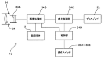
図1(A)は本実施の形態の撮像装置10のカバーが閉塞位置P1にある状態を示す斜視図、(B)は撮像装置10のカバーが開放位置P2にある状態を示す斜視図、図2は撮像装置10を後方から見た斜視図、図3は撮像装置10の構成を示すブロック図である。
Next, embodiments of the present invention will be described with reference to the drawings.
In the present embodiment, a case where the electronic apparatus is the imaging device 10 will be described.
FIG. 1A is a perspective view showing a state in which the cover of the imaging apparatus 10 of the present embodiment is in the closed position P1, and FIG. 1B is a perspective view showing a state in which the cover of the imaging apparatus 10 is in the open position P2. 2 is a perspective view of the imaging apparatus 10 as viewed from the rear, and FIG. 3 is a block diagram illustrating the configuration of the imaging apparatus 10.

図1(A)、(B)、図2に示すように、本実施の形態の撮像装置10はデジタルスチルカメラである。
撮像装置10は、外装を構成する筐体12を有している。なお、本明細書において前方とは被写体側をいい、後方とは結像側をいい、撮像装置10の左右は前方から見た状態でいうものとする。
筐体12は、前後方向の厚さと、厚さよりも大きい寸法の上下方向の高さと、高さよりも大きい寸法の左右方向の幅を有し、扁平な薄い矩形板状に形成されている。
筐体12は前方に臨む前面14と、後方に臨む後面16と、上方に臨む上面18と、下方に臨む下面と、左右に臨む左右の側面20、22とを有している。
前面14には、後述する支持機構38(図15、図16)によって支持されたカバー36が設けられている。
図1(B)に示すように、筐体12の右側部には、撮影光学系24を収容するレンズ鏡筒26(図8)が上下方向に延在して設けられ、撮影光学系24の最も前方に対物レンズが位置している。
本実施の形態において撮影光学系24はズーム率が可変のズーム光学系で構成されている。
筐体12の前面14上部の右側部寄りの箇所には、開口が設けられ、撮影光学系24の最も前部に配置される撮影レンズ24Aが前記開口を介して前方に臨んで設けられている。
なお、撮影光学系24は、撮影レンズ24Aに加えて、何れも図示しないが、撮影レンズ24Aの後方に位置し光路を90度下方に屈曲させるプリズム、該プリズムの下方に前記光路に沿って配置された複数のレンズ、光路上に配置された絞り機構などを含んで構成されている。
前面14の撮影レンズ24Aの左側部には、焦点距離測定用の照明光などを照射する発光部28A、照明補助光(閃光)を発光するフラッシュ部28Bなどが設けられている。
図2に示すように、筐体12の上面18には、電源スイッチ30A、シャッタボタン30Bが設けられている。
筐体12の後面16の上部右側部には、撮影モード、再生モードの切替など種々の操作を行なうための操作スイッチ30Cが設けられ、後面16の上部左側部には、撮影光学系24のズーム率を望遠側(テレ側)に調整する望遠スイッチ30Dと、撮影光学系24のズーム率を広角側(ワイド側)に調整する広角スイッチ30Eとが上下に並べられて設けられている。
後面16の中央には、撮像した映像などを表示するディスプレイ32が設けられている。
As shown in FIGS. 1A, 1B, and 2, the imaging device 10 of the present embodiment is a digital still camera.
The imaging device 10 has a housing 12 that forms an exterior. In the present specification, the front refers to the subject side, the rear refers to the imaging side, and the left and right sides of the imaging device 10 are viewed from the front.
The casing 12 has a flat and thin rectangular plate shape having a thickness in the front-rear direction, a height in the vertical direction larger than the thickness, and a width in the left-right direction larger than the height.
The housing 12 has a front surface 14 facing forward, a rear surface 16 facing rear, an upper surface 18 facing upward, a lower surface facing downward, and left and right side surfaces 20 and 22 facing left and right.
The front surface 14 is provided with a cover 36 supported by a support mechanism 38 (FIGS. 15 and 16) described later.
As shown in FIG. 1B, a lens barrel 26 (FIG. 8) that accommodates the photographing optical system 24 is provided on the right side of the housing 12 so as to extend in the vertical direction. The objective lens is located in the forefront.
In the present embodiment, the photographing optical system 24 is composed of a zoom optical system with a variable zoom rate.
An opening is provided at a location near the right side of the upper portion of the front surface 14 of the housing 12, and a photographing lens 24 </ b> A disposed at the foremost part of the photographing optical system 24 is provided facing the front through the opening. .
Although the photographic optical system 24 is not shown in addition to the photographic lens 24A, a prism that is located behind the photographic lens 24A and bends the optical path downward by 90 degrees is disposed along the optical path below the prism. And a plurality of lenses, a diaphragm mechanism arranged on the optical path, and the like.
On the left side of the photographing lens 24A on the front surface 14, a light emitting unit 28A for emitting illumination light for measuring a focal length, a flash unit 28B for emitting illumination auxiliary light (flash), and the like are provided.
As shown in FIG. 2, a power switch 30 </ b> A and a shutter button 30 </ b> B are provided on the upper surface 18 of the housing 12.
An operation switch 30C for performing various operations such as switching between a shooting mode and a reproduction mode is provided on the upper right side of the rear surface 16 of the housing 12, and a zoom of the shooting optical system 24 is provided on the upper left side of the rear surface 16. A telephoto switch 30D that adjusts the zoom ratio to the telephoto side (telephoto side) and a wide-angle switch 30E that adjusts the zoom ratio of the photographing optical system 24 to the wide-angle side (wide side) are arranged vertically.
In the center of the rear surface 16, a display 32 for displaying captured images and the like is provided.

図3に示すように、撮像装置10は、撮影光学系24によって結像された被写体像を撮像するCCDやCMOSセンサなどで構成された撮像素子34A、該撮像素子34Aから出力された撮像信号に基づいて画像データを生成し、メモリカードなどの記録媒体2に記録する画像処理部34B、前記画像データをディスプレイ32に表示させる表示処理部34C、各操作スイッチ30A〜30Eの操作に応じて画像処理部34B、表示処理部34Cを制御するCPUなどを含む制御部34Dなどを備えている。   As illustrated in FIG. 3, the imaging device 10 includes an imaging element 34A configured by a CCD or CMOS sensor that captures a subject image formed by the imaging optical system 24, and an imaging signal output from the imaging element 34A. An image processing unit 34B that generates image data based on the image data and records the image data on the recording medium 2 such as a memory card, a display processing unit 34C that displays the image data on the display 32, and image processing according to operations of the operation switches 30A to 30E. A control unit 34D including a CPU for controlling the unit 34B and the display processing unit 34C is provided.

次にカバー36および支持機構38について説明する。
図1(A)、(B)に示すように、カバー36は、前面14に、閉塞位置P1と開放位置P2との間で移動可能に配置されている。
前面14は、カバー36の閉塞位置P1でカバー36により覆われカバー36の開放位置P2で開放される開閉用面40と、カバー36の閉塞位置P1で開放されカバー36の開放位置P2でカバー36により覆われる非開閉用面42とを有し、開閉用面40と非開閉用面42との間は中間面41となっている。
本実施の形態では、開閉用面40に、撮影レンズ24A、発光部28A、フラッシュ部28Bが配置されている。
Next, the cover 36 and the support mechanism 38 will be described.
As shown in FIGS. 1A and 1B, the cover 36 is disposed on the front surface 14 so as to be movable between a closed position P1 and an open position P2.
The front surface 14 is covered with the cover 36 at the closed position P1 of the cover 36 and is opened at the open position P2 of the cover 36. The front surface 14 is opened at the closed position P1 of the cover 36 and the cover 36 is opened at the open position P2 of the cover 36. The non-opening / closing surface 42 is covered with an intermediate surface 41 between the opening / closing surface 40 and the non-opening / closing surface 42.
In the present embodiment, the photographing lens 24A, the light emitting unit 28A, and the flash unit 28B are arranged on the opening / closing surface 40.

カバー36は、カバー36の移動方向と直交する方向の幅を有し、カバー36の幅は前面14の幅と同一であり、カバー36が閉塞位置P1に位置した状態で、カバー36と非開閉用面42とにより筐体12の前面が構成される。   The cover 36 has a width in a direction perpendicular to the moving direction of the cover 36, the width of the cover 36 is the same as the width of the front surface 14, and the cover 36 is not opened and closed with the cover 36 positioned at the closed position P <b> 1. The front surface of the housing 12 is constituted by the work surface 42.

図15(T)、(V)、図16(W)に示すように、支持機構38は、カバー36を閉塞位置P1と開放位置P2との間で移動可能に支持するものであり、支持機構38は、2つの第1当接部材44Cと、1つの第2当接部材48Gと、2つの第3当接部材44Dと、第1ガイド面50Cと、第2ガイド面50Dと、第3ガイド面50Eと、揺動規制機構とを含んで構成されている。   As shown in FIGS. 15T, 15V, and 16W, the support mechanism 38 supports the cover 36 so as to be movable between the closed position P1 and the open position P2. 38, two first contact members 44C, one second contact member 48G, two third contact members 44D, a first guide surface 50C, a second guide surface 50D, and a third guide. The surface 50E and the rocking restriction mechanism are included.

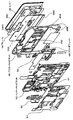
より詳細に説明すると、図4、図5は、筐体12の前面部分およびカバー36の分解斜視図である。
筐体12の前面部分は、前面14を構成するアウターキャビネット46、アウターキャビネット46の後面に配置されるインナーキャビネット50、インナーキャビネット50の後面に配置されるフィルム54とを含んで構成されている。
また、カバー36の後面にはフレーム44と、スライダプレート48とが配置されている。
More specifically, FIGS. 4 and 5 are exploded perspective views of the front portion of the housing 12 and the cover 36.
The front surface portion of the housing 12 includes an outer cabinet 46 constituting the front surface 14, an inner cabinet 50 disposed on the rear surface of the outer cabinet 46, and a film 54 disposed on the rear surface of the inner cabinet 50.
A frame 44 and a slider plate 48 are disposed on the rear surface of the cover 36.

図4、図5、図30(A)、(B)に示すように、アウターキャビネット46はアルミで形成され、アウターキャビネット46は、矩形板状の本体板部46Aと、本体板部46Aの周囲から後方に起立する4つの側板部46Bとを備えている。
本体板部46Aの前面が筐体12の前面14を構成し、各側板部46Bが筐体12の上面18、下面、左右の側面20、22の前部寄りの箇所を構成している。
図4、図30に示すように、開閉用面40と中間面41と非開閉用面42は本体板部46Aの前面で構成され、中間面41はカバー36の位置に拘わらずカバー36により常時隠される。
非開閉用面42は、開閉用面40に比べてカバー36の厚さ分突出し、すなわち、非開閉用面42は開閉用面40よりも前方に位置し、それら非開閉用面42と開閉用面40は平行している。
中間面41は前後方向において開閉用面40と非開閉用面42との中間に位置している。
なお、中間面41には、後述する第1ガイドピン44A、2つの取り付け片44B、2つの第1当接部材44C、1つの第2当接部材48Gと、2つの第3当接部材44Dと、第1係止片44G、第2係止片48D、ばね係止片48Eなどが挿通される複数の開口が形成されている。
また、図5に示すように、中間面41の後面には、トグルばね56の一端が係止される係止ピン46Cが後方に向けて突設されている。
As shown in FIGS. 4, 5, 30A, and 30B, the outer cabinet 46 is formed of aluminum, and the outer cabinet 46 includes a rectangular plate-like main body plate portion 46A and a periphery of the main body plate portion 46A. And four side plate portions 46B standing rearward.
The front surface of the main body plate portion 46 </ b> A constitutes the front surface 14 of the housing 12, and each side plate portion 46 </ b> B constitutes a portion closer to the front portion of the upper surface 18, lower surface, and left and right side surfaces 20, 22 of the housing 12.
As shown in FIGS. 4 and 30, the opening / closing surface 40, the intermediate surface 41, and the non-opening / closing surface 42 are constituted by the front surface of the main body plate portion 46 </ b> A. Hidden.
The non-opening / closing surface 42 protrudes by the thickness of the cover 36 as compared to the opening / closing surface 40, that is, the non-opening / closing surface 42 is located in front of the opening / closing surface 40, and the non-opening / closing surface 42 and the opening / closing surface are opened. The planes 40 are parallel.
The intermediate surface 41 is located between the opening / closing surface 40 and the non-opening / closing surface 42 in the front-rear direction.
The intermediate surface 41 includes a first guide pin 44A, two attachment pieces 44B, two first contact members 44C, one second contact member 48G, and two third contact members 44D, which will be described later. A plurality of openings through which the first locking piece 44G, the second locking piece 48D, the spring locking piece 48E and the like are inserted are formed.
As shown in FIG. 5, a locking pin 46 </ b> C that locks one end of the toggle spring 56 is provided on the rear surface of the intermediate surface 41 so as to protrude rearward.

図4、図5に示すように、インナーキャビネット50は、アウターキャビネット46の本体板部46Aの後面に接着剤によって取り付けられている。
インナーキャビネット50は、アウターキャビネット46の本体板部46Aおよび側板部46Bの内側に収容可能な大きさの矩形板状を呈しており、本実施の形態では、合成樹脂製である。
インナーキャビネット50は、図31に示すように、第1、第2ガイド溝50A、50Bと、第1、第2、第3ガイド面50C、50D、50Eとを含んで構成されている。
図6に示すように、第1、第2ガイド溝50A、50Bは、カバー36の移動方向に延在する単一の直線上でカバー36の移動方向に間隔をおいた2箇所に設けられており、第1、第2ガイド溝50A、50Bにそれぞれ第1、第2ガイドピン44A、48Fが挿通されることで、フレーム44およびカバー36がカバー36の移動方向に案内されるとともに、第1、第2ガイドピン44A、48Fが第1、第2ガイド溝50A、50Bの延在方向の一方の端部に当接した状態で閉塞位置P1が決定され、第1、第2ガイドピン44A、48Fが第1、第2ガイド溝50A、50Bの延在方向の他方の端部に当接した状態で開放位置P2が決定される。なお、ガイドピン、ガイド溝は1つでもよいが、実施の形態のように2つ設けると、カバーの移動を円滑に行う上で有利となる。
As shown in FIGS. 4 and 5, the inner cabinet 50 is attached to the rear surface of the main body plate portion 46 </ b> A of the outer cabinet 46 with an adhesive.
The inner cabinet 50 has a rectangular plate shape that can be accommodated inside the main body plate portion 46A and the side plate portion 46B of the outer cabinet 46, and is made of synthetic resin in the present embodiment.
As shown in FIG. 31, the inner cabinet 50 includes first and second guide grooves 50A and 50B and first, second, and third guide surfaces 50C, 50D, and 50E.
As shown in FIG. 6, the first and second guide grooves 50 </ b> A and 50 </ b> B are provided at two positions spaced apart in the movement direction of the cover 36 on a single straight line extending in the movement direction of the cover 36. The first and second guide pins 44A and 48F are inserted into the first and second guide grooves 50A and 50B, respectively, so that the frame 44 and the cover 36 are guided in the moving direction of the cover 36, and the first The closing position P1 is determined in a state where the second guide pins 44A and 48F are in contact with one end in the extending direction of the first and second guide grooves 50A and 50B, and the first and second guide pins 44A, The open position P2 is determined in a state in which 48F is in contact with the other end in the extending direction of the first and second guide grooves 50A and 50B. Although one guide pin and one guide groove may be provided, providing two as in the embodiment is advantageous in smoothly moving the cover.

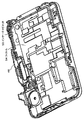
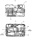
図6は筐体12の前面部分を後方から見た斜視図、図7は筐体12の前面部分が後方に臨む面がフィルム54で覆われた状態を示す斜視図、図8はインナーキャビネット50の後方に配置されるレンズ鏡筒26や電子部品27がインナーキャビネット50に臨む面がフィルム54で覆われた状態を示す斜視図である。
図9、図10、図12は筐体12の前面部分からアウターキャビネット46を除いて前方から見た斜視図、図11は図10のA部拡大斜視図、図12は図11のB部拡大斜視図である。
6 is a perspective view of the front surface portion of the housing 12 as seen from the rear, FIG. 7 is a perspective view showing a state in which the front surface portion of the housing 12 faces the rear, and is covered with a film 54, and FIG. 2 is a perspective view showing a state in which the surface of the lens barrel 26 and the electronic component 27 arranged behind the front face of the inner cabinet 50 is covered with a film 54. FIG.
9, FIG. 10 and FIG. 12 are perspective views as seen from the front, excluding the outer cabinet 46 from the front portion of the housing 12, FIG. 11 is an enlarged perspective view of portion A in FIG. 10, and FIG. 12 is an enlarged view of portion B in FIG. It is a perspective view.

図14(A)はカバー36が閉塞位置P1に位置した状態を示す正面図、(B)は図14(A)のB矢視図、(C)は図14(A)のC矢視図である。図15(T)は図14(A)のTT線断面図、(U)は図14(A)のUU線断面図、(V)は図14(A)のVV線断面図である。図16(W)は図14(A)のWW線断面図、(X)は図14(A)のXX線断面図である。図17(A)はカバー36が閉塞位置P1に位置した状態を前方から見たインナーキャビネット50、スライダプレート48の位置関係を示す正面図、(B)はカバー36が閉塞位置P1に位置した状態を後方から見たインナーキャビネット50、スライダプレート48の位置関係を示す背面図である。   14A is a front view showing a state in which the cover 36 is located at the closed position P1, FIG. 14B is a view as seen from the arrow B in FIG. 14A, and FIG. 14C is a view as seen from the arrow C in FIG. It is. 15 (T) is a cross-sectional view taken along line TT in FIG. 14 (A), (U) is a cross-sectional view taken along line UU in FIG. 14 (A), and (V) is a cross-sectional view taken along line VV in FIG. 16 (W) is a cross-sectional view taken along the line WW in FIG. 14 (A), and (X) is a cross-sectional view taken along the line XX in FIG. 14 (A). 17A is a front view showing the positional relationship between the inner cabinet 50 and the slider plate 48 when the cover 36 is located at the closed position P1, as viewed from the front. FIG. 17B is a state where the cover 36 is located at the closed position P1. 6 is a rear view showing the positional relationship between the inner cabinet 50 and the slider plate 48 as viewed from the rear.

図18(A)はカバー36が閉塞位置P1から開放位置P2に向けて移動しつつある状態を示す正面図、(B)は図18(A)のB矢視図、(C)は図18(A)のC矢視図である。図19(F)は図18(A)のFF線断面図、(G)は図18(A)のGG線断面図、(I)は図18(A)のII線断面図である。図20(R)は図18(A)のRR線断面図、(S)は図18(A)のSS線断面図である。図21(A)はカバー36が閉塞位置P1から開放位置P2に向けて移動しつつある状態を前方から見たインナーキャビネット50、スライダプレート48の位置関係を示す正面図、(B)はカバー36が閉塞位置P1から開放位置P2に向けて移動した状態を後方から見たインナーキャビ50、スライダプレート48の位置関係を示す背面図である。   18A is a front view showing a state in which the cover 36 is moving from the closed position P1 toward the open position P2, FIG. 18B is a view taken in the direction of arrow B in FIG. 18A, and FIG. It is C arrow line view of (A). 19F is a cross-sectional view taken along line FF in FIG. 18A, FIG. 19G is a cross-sectional view taken along line GG in FIG. 18A, and FIG. 19I is a cross-sectional view taken along line II in FIG. 20R is a cross-sectional view taken along the line RR in FIG. 18A, and FIG. 20S is a cross-sectional view taken along the line SS in FIG. 21A is a front view showing the positional relationship between the inner cabinet 50 and the slider plate 48 when the cover 36 is moving from the closed position P1 toward the open position P2 when viewed from the front, and FIG. FIG. 6 is a rear view showing the positional relationship between the inner cavity 50 and the slider plate 48 as viewed from the rear in a state where the valve has moved from the closed position P1 toward the open position P2.

図22(A)はカバー36が後方に向けて押圧されつつ閉塞位置P1から開放位置P2に向けて移動しつつある状態を示す正面図、(B)は図22(A)のB矢視図、(C)は図22(A)のC矢視図である。図23(J)は図22(A)のJJ線断面図、(K)は図22(A)のKK線断面図、(L)は図22(A)のLL線断面図である。   22A is a front view showing a state in which the cover 36 is being moved toward the open position P2 from the closed position P1 while being pressed rearward, and FIG. 22B is a view taken in the direction of arrow B in FIG. (C) is a C arrow view of FIG. 22 (A). 23J is a cross-sectional view taken along line JJ in FIG. 22A, FIG. 23K is a cross-sectional view taken along line KK in FIG. 22A, and FIG. 23L is a cross-sectional view taken along line LL in FIG.

図24(A)はカバー36が開放位置P2に位置した状態を示す正面図、(B)は図24(A)のB矢視図、(C)は図24(A)のC矢視図である。図25(D)は図24(A)のDD線断面図、(E)は図24(A)のEE線矢視図、(H)は図24(A)のHH線断面図である。図26(Q)は図24(A)のQQ線断面図であり、(Y)は図24(A)のYY線断面図である。図27(A)はカバー36が開放位置P2に位置した状態を前方から見たインナーキャビネット50、スライダプレート48の位置関係を示す正面図、(B)はカバー36が開放位置P2に位置した状態を後方から見たインナーキャビネット50、スライダプレート48の位置関係を示す背面図である。   24A is a front view showing a state in which the cover 36 is located at the open position P2, FIG. 24B is a view as seen from the arrow B in FIG. 24A, and FIG. 24C is a view as seen from the arrow C in FIG. It is. 25D is a sectional view taken along the line DD in FIG. 24A, FIG. 25E is a sectional view taken along the line EE in FIG. 24A, and FIG. 25H is a sectional view taken along the line HH in FIG. 26 (Q) is a cross-sectional view taken along the line QQ in FIG. 24 (A), and (Y) is a cross-sectional view taken along the line YY in FIG. 24 (A). FIG. 27A is a front view showing the positional relationship between the inner cabinet 50 and the slider plate 48 when the cover 36 is located at the open position P2, and FIG. 27B is a state where the cover 36 is located at the open position P2. 6 is a rear view showing the positional relationship between the inner cabinet 50 and the slider plate 48 as viewed from the rear.

図28(A)はカバー36が閉塞位置P1の直前に位置した状態を示す正面図、(B)は図28(A)のB矢視図、(C)は図22(A)のC矢視図である。図29(M)は図28(A)のMM線断面図、(N)は図28(A)のNN線断面図、(O)は図28(A)のOO線断面図、(P)は図28(A)PP線断面図である。   28A is a front view showing a state in which the cover 36 is located immediately before the closing position P1, FIG. 28B is a view taken in the direction of the arrow B in FIG. 28A, and FIG. 28C is a view of the arrow C in FIG. FIG. 29 (M) is a cross-sectional view taken along the line MM in FIG. 28 (A), (N) is a cross-sectional view taken along the line NN in FIG. 28 (A), (O) is a cross-sectional view taken along the line OO in FIG. FIG. 28A is a cross-sectional view taken along the PP line.

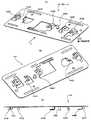
図30(A)はアウターキャビネット46の斜視図、(B)はアウターキャビネット46の前後を反転した斜視図、図31(A)はインナーキャビネット50の斜視図、(B)はインナーキャビネット50の前後を反転した斜視図、(C)は図31(A)のC部分の拡大斜視図、図32(A)、(B)はフレーム44の斜視図、(C)は図32(A)のC矢視図、図33(A)はスライダプレート48の斜視図、(B)はスライダプレート48の前後を反転した斜視図である。   30A is a perspective view of the outer cabinet 46, FIG. 30B is a perspective view in which the front and rear of the outer cabinet 46 are reversed, FIG. 31A is a perspective view of the inner cabinet 50, and FIG. (C) is an enlarged perspective view of a portion C in FIG. 31 (A), FIGS. 32 (A) and 32 (B) are perspective views of the frame 44, and (C) is C in FIG. 32 (A). FIG. 33A is a perspective view of the slider plate 48, and FIG. 33B is a perspective view in which the front and rear of the slider plate 48 are reversed.

第1ガイド面50Cは、図9乃至図13に示すように、カバー36の移動方向に沿って延在し、閉塞位置P1と開放位置P2との間で2つの第1当接部材44Cに当接可能に設けられている。
第1ガイド面50Cは、図13、図15(T)に示すように、閉塞位置P1で第1当接部材44Cが当接される底面部5002と、底面部5002に比べてカバー36の厚さ分突出した箇所で開放位置P2において第1当接部材44Cが当接される箇所から開閉用面40に向かって非開閉用面42に平行して延在する平坦ガイド面部5004と、平坦ガイド面部5004の開閉用面40寄りの箇所で平坦ガイド面部5004と底面部5002とを接続し底面部5002に至るにつれて低位となる傾斜面部5006とで構成されている。
As shown in FIGS. 9 to 13, the first guide surface 50C extends along the moving direction of the cover 36, and contacts the first contact members 44C between the closed position P1 and the open position P2. It is provided so that it can touch.
As shown in FIGS. 13 and 15 (T), the first guide surface 50C has a bottom surface portion 5002 with which the first contact member 44C abuts at the closing position P1, and the thickness of the cover 36 compared to the bottom surface portion 5002. A flat guide surface portion 5004 extending in parallel to the non-opening / closing surface 42 from the portion where the first contact member 44C is in contact at the open position P2 at the protruding position to the opening / closing surface 40, and a flat guide A flat guide surface portion 5004 and a bottom surface portion 5002 are connected at a location near the opening / closing surface 40 of the surface portion 5004, and an inclined surface portion 5006 that becomes lower as it reaches the bottom surface portion 5002.

第2ガイド面50Dは、図16(W)、図31に示すように、カバー36の移動方向に沿って延在し、閉塞位置P1と開放位置P2との間で第2当接部材48Gに当接可能に設けられている。
第2ガイド面50Dは、図16(W)、図31に示すように、閉塞位置P1で第1当接部材44Cが当接される底面部5012と、底面部5012に比べてカバー36の厚さ分突出した箇所で開放位置P2において第2当接部材48Gが当接される箇所から開閉用面40に向かって非開閉用面42に平行して延在する平坦ガイド面部5014と、平坦ガイド面部5014の開閉用面40寄りの箇所で平坦ガイド面部5014と底面部5012とを接続し底面部5012に至るにつれて低位となる傾斜面部5016とで構成されている。
As shown in FIGS. 16 (W) and 31, the second guide surface 50 </ b> D extends along the moving direction of the cover 36. It is provided so that it can contact.
As shown in FIGS. 16 (W) and 31, the second guide surface 50 </ b> D has a bottom surface portion 5012 with which the first contact member 44 </ b> C abuts at the closing position P <b> 1 and a thickness of the cover 36 compared to the bottom surface portion 5012. A flat guide surface portion 5014 extending in parallel with the non-opening / closing surface 42 from the position where the second contact member 48G contacts the open position P2 at the protruding position, and the flat guide A flat guide surface portion 5014 and a bottom surface portion 5012 are connected at a position near the opening / closing surface 40 of the surface portion 5014, and an inclined surface portion 5016 that becomes lower as the bottom surface portion 5012 is reached.

第3ガイド面50Eは、図15(V)、図31に示すように、カバー36の閉塞位置P1およびその手前の位置で第3当接部材44Dが当接可能に設けられている。
第3ガイド面50Eは、開閉用面40側に至るにつれて前面14の後方に位置する傾斜した傾斜面で構成されている。
As shown in FIGS. 15 (V) and 31, the third guide surface 50 </ b> E is provided so that the third abutting member 44 </ b> D can abut at the closed position P <b> 1 of the cover 36 and a position in front thereof.
The third guide surface 50E is an inclined surface that is inclined to the rear of the front surface 14 toward the opening / closing surface 40 side.

また、インナーキャビネット50には、後述する2つの取り付け片44B、2つの第1当接部材44C、1つの第2当接部材48G、2つの第3当接部材44D、第1係止片44G、第2係止片48Dなどが挿通される複数の開口を含んで構成されている。
図6に示すように、インナーキャビネット50の後面の右側部寄りの箇所には、前記開口に臨ませてサイドレール52が取着されている。
サイドレール52は、カバー36の移動方向に直線状に延在する板状を呈している。
また、インナーキャビネット50の後面の左側部寄りの箇所には、インナーキャビネット50の複数の開口に臨ませてカバー36の移動方向に直線状に延在する係止縁部50Fが形成されている。
Further, the inner cabinet 50 includes two attachment pieces 44B, two first contact members 44C, one second contact member 48G, two third contact members 44D, a first locking piece 44G, which will be described later. A plurality of openings through which the second locking pieces 48D and the like are inserted are configured.
As shown in FIG. 6, a side rail 52 is attached to a position near the right side portion of the rear surface of the inner cabinet 50 so as to face the opening.
The side rail 52 has a plate shape extending linearly in the moving direction of the cover 36.
Further, a locking edge portion 50 </ b> F extending linearly in the moving direction of the cover 36 is formed at a position near the left side portion of the rear surface of the inner cabinet 50 so as to face the plurality of openings of the inner cabinet 50.

また、図4、図5に示すように、カバー36の背面にはフレーム44と、スライダプレート48とが配置されている。
フレーム44は、カバー36とほぼ同じ大きさの矩形板状を呈する板金で形成され、フレーム44の前面が両面粘着シート4402によってカバー36の後面に取着されている。
図32に示すように、フレーム44の後面には、第1ガイドピン44A、2つの取り付け片44B、2つの第1当接部材44C、2つの第3当接部材44D、第1係止片44Gなどが設けられている。
第1ガイドピン44Aは、図9乃至図13に示すように、フレーム44の後面の幅方向の中間部から後方に向けて突設され、インナーキャビネット50の第1ガイド溝50Aによってカバー36の移動方向に移動可能に左右方向に(カバー36の幅方向に)移動不能に案内される。
2つの取り付け片44Bは、図32に示すように、フレーム44の後面の左側部寄りで左右方向に間隔をおいた2箇所から屈曲形成され、スライダプレート48を取り付けるための雌ねじが形成されている。
2つの第1当接部材44Cは、フレーム44の後面の左右方向の両側寄りの2箇所から後方に向けて突設され、それらの先端は凸状の球面(曲面)を呈している。
各第1当接部材44Cは、閉塞位置P1と開放位置P2との間で2つの第1ガイド面50Cに当接しつつ移動する。
第3当接部材44Dは、図15(V)に示すように、第1当接部材44Cが第1ガイド面50Cに当接する方向と反対の方向から第3ガイド面50Eに当接可能に設けられている。
本実施の形態では、第3当接部材44Dは、図6、図15(V)、図32に示すように、フレーム44の後面の左右方向の両側寄りの2箇所から左右外側に屈曲形成され、開閉用面40に近づくにつれて後方に位置する傾斜板として形成されている。
第3当接部材44Dは第3ガイド面50Eに対して、第1当接部材44Cが底面部5002と、平坦ガイド面部5004の傾斜面部5006寄りの箇所との間を移動する間当接し、カバー36が開放位置P2から閉塞位置P1に戻る際にカバー36を前方から後方に変位させる。
第1係止片44G(第5当接部材)は、フレーム44の後面の右側部寄りの箇所から右側方に屈曲形成され、図6に示すように、サイドレール52(第5ガイド面)に係止することで、フレーム44およびカバー36の前方への移動範囲を規制するものである。
As shown in FIGS. 4 and 5, a frame 44 and a slider plate 48 are disposed on the back surface of the cover 36.
The frame 44 is formed of a sheet metal having a rectangular plate shape substantially the same size as the cover 36, and the front surface of the frame 44 is attached to the rear surface of the cover 36 by a double-sided adhesive sheet 4402.
As shown in FIG. 32, on the rear surface of the frame 44, there are a first guide pin 44A, two attachment pieces 44B, two first contact members 44C, two third contact members 44D, and a first locking piece 44G. Etc. are provided.
As shown in FIGS. 9 to 13, the first guide pin 44 </ b> A protrudes rearward from an intermediate portion in the width direction of the rear surface of the frame 44, and the cover 36 is moved by the first guide groove 50 </ b> A of the inner cabinet 50. It is guided so as not to move in the left-right direction (in the width direction of the cover 36) so as to be movable in the direction.
As shown in FIG. 32, the two attachment pieces 44B are bent at two positions spaced in the left-right direction near the left side of the rear surface of the frame 44, and female threads for attaching the slider plate 48 are formed. .
The two first abutting members 44C project rearward from two locations on the rear surface of the frame 44 near both sides in the left-right direction, and their tips have a convex spherical surface (curved surface).
Each first contact member 44C moves between the closed position P1 and the open position P2 while contacting the two first guide surfaces 50C.
As shown in FIG. 15 (V), the third contact member 44D is provided so as to be able to contact the third guide surface 50E from a direction opposite to the direction in which the first contact member 44C contacts the first guide surface 50C. It has been.
In the present embodiment, the third abutting member 44D is bent and formed on the left and right sides from two positions on the rear surface of the frame 44 near both sides in the left-right direction, as shown in FIG. 6, FIG. 15 (V), and FIG. It is formed as an inclined plate positioned rearward as it approaches the opening / closing surface 40.
The third abutting member 44D abuts against the third guide surface 50E while the first abutting member 44C moves between the bottom surface portion 5002 and a portion near the inclined surface portion 5006 of the flat guide surface portion 5004, and the cover When the cover 36 returns from the open position P2 to the closed position P1, the cover 36 is displaced from the front to the rear.
The first locking piece 44G (fifth contact member) is formed to bend rightward from a position near the right side of the rear surface of the frame 44, and as shown in FIG. By locking, the forward moving range of the frame 44 and the cover 36 is restricted.

図5に示すように、フレーム44の後面の上部と下部には、それぞれ左右方向に延在する帯状のクッションシート58A、58Bが接着により取着され、フレーム44の後面とアウターキャビネット46の前面(筐体12の前面14)との摩擦による傷の防止が図られ、また、カバー36の前後方向のガタツキの防止が図られている。
なお、図4に示す符号58Cは摩擦抵抗が少ない合成樹脂で形成された滑りシートであり、フレーム44の後面の上部の左右方向の中央部に取着され、図23に示すように、フレーム44およびカバー36が閉塞位置P1から開放位置P2に移動する際にフレーム44およびカバー36が第1当接部材44Cを支点としてカバー36の上端が後方に傾いた場合、滑りシート58Cの下端がアウターキャビネット46の前面に設けられた中間面41の上端に接触することで円滑に摺動するように図られている。
As shown in FIG. 5, belt-like cushion sheets 58A and 58B extending in the left-right direction are respectively attached to the upper and lower portions of the rear surface of the frame 44 by adhesion, and the rear surface of the frame 44 and the front surface of the outer cabinet 46 ( It is possible to prevent scratches due to friction with the front surface 14) of the housing 12, and to prevent backlash of the cover 36 in the front-rear direction.
Reference numeral 58C shown in FIG. 4 is a sliding sheet formed of a synthetic resin having a low frictional resistance, and is attached to the central portion in the left-right direction at the upper part of the rear surface of the frame 44. As shown in FIG. When the frame 44 and the cover 36 are tilted backward with the first contact member 44C as a fulcrum when the cover 36 moves from the closed position P1 to the open position P2, the lower end of the sliding seat 58C is the outer cabinet. 46 is designed to slide smoothly by contacting the upper end of the intermediate surface 41 provided on the front surface of 46.

スライダプレート48はばね鋼板から構成され、図33に示すように、平面視直線状に延在する横片部48Aと、横片部48Aの両側から横片部48Aの延在方向と直交する方向にそれぞれ延出された第1縦片部48Bおよび第2縦片部48Cとを有している。
第1、第2縦片部48B、48Cの先端にはねじ挿通孔が設けられている。
図6に示すように、フレーム44の2つの取り付け片44Bをアウターキャビネット46の開口を介して後方に臨ませた状態で、ねじが第1、第2縦片部48B、48Cのねじ挿通孔を介して各取り付け片44Bのねじ孔に螺合することでスライダプレート48がフレーム44に取り付けられる。
第1縦片部48Bの先端には第2係止片48D(第5当接部材)が突設され、図6に示すように、第2係止片48Dがインナーキャビネット50の係止縁部50F(第5ガイド面)に係止されることでスライダプレート48、フレーム44およびカバー36の前方への移動を規制するものである。
第2縦片部48Cの先端にはトグルばね56の他端が係止されるばね係止片48Eが突設されている。
図33(B)に示すように、横片部48Aの延在方向の中間部には、第2ガイドピン48Fが後方に向けて突設されている。第2ガイドピン48Fは第2ガイド溝50Bによってカバー36の移動方向に移動可能に左右方向に移動不能に案内される。
図33(B)に示すように、横片部48Aの延在方向の一端寄りには、第2当接部材48Gが設けられている。
第2当接部材48Gは、後方に向けて突設され、その先端は凸状の球面(曲面)を呈している。
第2当接部材48Gは、図16(W)に示すように、閉塞位置P1と開放位置P2との間で第2ガイド面50Dに当接しつつ移動する。
図9、図33(A)に示すように、に示すように、横片部48Aの延在方向の両端には、第4当接部材48Hが前方に向けて突設され、その先端は凸状の曲面を呈している。
第4当接部材48Hは、図16(X)に示すように、非開閉用面42の後面に設けられた第4ガイド面46Dに対面するように設けられている。
そして、図23(L)に示すように、カバー36が2つの第1当接部材44Cを支点としてカバー36の下部が非開閉用面42から離間する方向に(前方に)揺動した場合に、第4当接部材48Hが非開閉用面42の第4ガイド面46Dに当接することでカバー36の非開閉面42寄りの箇所の前方への変位を阻止する。なお、本実施の形態では、第4当接部材48Hはスライダプレート48に一体に設けられており弾性変形可能であるので、理論的には、第4当接部材48Hが弾性変形する間、カバー36の非開閉面42寄りの箇所が前方に変位することになる。
The slider plate 48 is made of a spring steel plate, and as shown in FIG. 33, the horizontal piece portion 48A extending linearly in plan view, and the direction orthogonal to the extending direction of the horizontal piece portion 48A from both sides of the horizontal piece portion 48A. The first vertical piece portion 48B and the second vertical piece portion 48C are respectively extended.
Screw insertion holes are provided at the tips of the first and second vertical piece portions 48B and 48C.
As shown in FIG. 6, with the two attachment pieces 44B of the frame 44 facing rearward through the opening of the outer cabinet 46, the screws are inserted into the screw insertion holes of the first and second vertical piece portions 48B and 48C. The slider plate 48 is attached to the frame 44 by being screwed into the screw holes of the attachment pieces 44B.
A second locking piece 48D (fifth contact member) protrudes from the tip of the first vertical piece 48B, and the second locking piece 48D is a locking edge of the inner cabinet 50 as shown in FIG. The slider plate 48, the frame 44, and the cover 36 are restricted from moving forward by being locked to 50F (fifth guide surface).
A spring locking piece 48E for locking the other end of the toggle spring 56 projects from the tip of the second vertical piece 48C.
As shown in FIG. 33 (B), a second guide pin 48F protrudes rearward from an intermediate portion in the extending direction of the horizontal piece portion 48A. The second guide pin 48F is guided by the second guide groove 50B so as to be movable in the moving direction of the cover 36 but not movable in the left-right direction.
As shown in FIG. 33B, a second abutting member 48G is provided near one end in the extending direction of the horizontal piece 48A.
The second contact member 48G protrudes rearward, and the tip thereof has a convex spherical surface (curved surface).
As shown in FIG. 16 (W), the second contact member 48G moves between the closed position P1 and the open position P2 while contacting the second guide surface 50D.
As shown in FIG. 9 and FIG. 33 (A), as shown in FIG. 9, fourth contact members 48H project forward from both ends of the lateral piece 48A in the extending direction, and the tips thereof are convex. It has a curved surface.
As shown in FIG. 16X, the fourth contact member 48H is provided so as to face the fourth guide surface 46D provided on the rear surface of the non-opening / closing surface 42.
Then, as shown in FIG. 23L, when the cover 36 swings in the direction away from the non-opening / closing surface 42 (forward) with the two first contact members 44C as fulcrums. The fourth abutting member 48H abuts against the fourth guide surface 46D of the non-opening / closing surface 42, thereby preventing forward displacement of the portion of the cover 36 near the non-opening / closing surface 42. In the present embodiment, the fourth contact member 48H is provided integrally with the slider plate 48 and can be elastically deformed. Therefore, theoretically, while the fourth contact member 48H is elastically deformed, the cover A portion near 36 of the non-opening / closing surface 42 is displaced forward.

トグルばね56は、一端が係止ピン46Cに係止され、他端がばね係止片48Eに係止されることで、アウターキャビネット46とカバー36との間に配設され、カバー36を閉塞位置P1および開放位置P2に切り換えて付勢するものである。
なお、本実施の形態では、図5、図6に示すように、トグルばね56は、インナーキャビネット50に取着される板状のばねカバー57によってトグルばね56が後方に臨む部分が覆われている。
One end of the toggle spring 56 is locked to the locking pin 46C and the other end is locked to the spring locking piece 48E, so that the toggle spring 56 is disposed between the outer cabinet 46 and the cover 36 and closes the cover 36. It switches to the position P1 and the open position P2, and is urged.
In the present embodiment, as shown in FIGS. 5 and 6, the toggle spring 56 is covered by a plate-like spring cover 57 attached to the inner cabinet 50 at a portion where the toggle spring 56 faces rearward. Yes.

なお、本実施の形態では、第1当接部材44Cが第1ガイド面50Cに当接する箇所を支点としたカバー36の揺動を規制する揺動規制機構が、第2当接部材48G、第2ガイド面50D、第4当接部材48H、第4ガイド面46D、第2係止片48D(第5当接部材)、係止縁部50F(第5ガイド面)を含んで構成されている。   In the present embodiment, the swing restricting mechanism that restricts the swing of the cover 36 with the first contact member 44C contacting the first guide surface 50C as a fulcrum is the second contact member 48G, 2 A guide surface 50D, a fourth contact member 48H, a fourth guide surface 46D, a second locking piece 48D (fifth contact member), and a locking edge 50F (fifth guide surface). .

次に開閉動作について説明する。
この開閉動作は、ユーザがカバー36を押さえつけずにカバー36の移動方向のみへの力を加えて開閉させる場合と、ユーザがカバー36を押さえつけながら開閉させる場合とが考えられるため、2つの場合についてそれぞれ説明する。
Next, the opening / closing operation will be described.
There are two cases in which the opening / closing operation may be performed when the user applies the force only in the moving direction of the cover 36 without pressing the cover 36 and when the user opens / closes the cover 36 while pressing the cover 36. Each will be explained.

[カバー36の移動方向のみへの力を加えてカバー36を開閉させる場合]
(閉塞位置)
図14乃至図17に示すように、第1当接部材44Cが第1ガイド面50Cの底面部5002上に当接している。
また、第2当接部材48Gが第2ガイド面50Dの底面部5012上に当接している。
また、第3当接部材44Dが第3ガイド面50Eに当接している。
トグルばね56によりカバー36は閉塞位置P1に付勢され、第3当接部材44Dが第3ガイド面50Eに当接することで、カバー36ががたつくことなく安定した状態で閉塞位置P1に位置する。閉塞位置P1では、フレーム44に設けられたクッションシート58Aと滑りシート58Cが開閉用面40に当接し、クッションシート58Bが中間面41に当接する。
また、カバー36が閉塞位置P1に位置した状態では、カバー36が筐体12の前面14とほぼ同一面を形成することで筐体12の前面の凹凸をなくすことができるため、携帯性の向上を図れるとともに、デザイン性が高められている。
(閉塞位置P1から開放位置への移動)
図18乃至図21に示すように、ユーザが閉塞位置P1から開放位置P2へ向かってカバー36を移動させると、第1当接部材44Cが第1ガイド面50Cの底面部5002から傾斜面部5006に当接しつつ上昇し、第2当接部材48Gが第2ガイド面50Dの底面部5012から傾斜面部5016を当接しつつ上昇し、カバー36が中間面41の前方に変位しつつ開放位置P2方向に移動していく。このとき、図21(B)に示すように、第1当接部材44Cが第1ガイド面50Cに当接する方向と反対の方向から第1、第2係止片44G、48Dがサイドレール52、係止縁部50Fに係止することでカバー36の前後方向のがたつきが防止されている。
やがて、第1当接部材44Cが第1ガイド面50Cの平坦ガイド面部5004に当接しつつ開放位置P2方向に向かって移動し、第2当接部材48Gが第2ガイド面50Dの平坦ガイド面部5014に当接しつつ開放位置P2方向に向かって移動し、カバー36は非開閉用面42と平行状態を維持しつつ開放位置P2方向に移動していく。このとき、第1当接部材44Cが第1ガイド面50Cに当接する方向と反対の方向から第1、第2係止片44G、48Dがサイドレール52、係止縁部50Fに係止することでカバー36の前後方向のがたつきが防止されている。
このとき、閉塞位置P1と開放位置P2との中間の箇所で、トグルばね56によるばねの付勢力の向きが変わり、カバー36は開放位置P2に付勢される。
そして、第1、第2ガイドピン44A、48Fが第1、第2ガイド溝50A、50Bの端部に当接した状態でカバー36は開放位置P2となる。
この開放位置P2では、図24乃至図27に示すように、第1当接部材44Cが第1ガイド面50Cの平坦ガイド面部5004に当接し、かつ、第2当接部材48Gが第2ガイド面50Dの平坦ガイド面部5014に当接し、さらに、図27(B)に示すように、第1当接部材44Cが第1ガイド面50Cに当接する方向と反対の方向から第1、第2係止片44G、48Dがサイドレール52、係止縁部50Fに係止することでカバー36の前後方向のがたつきが防止されている。
[When applying the force only in the moving direction of the cover 36 to open and close the cover 36]
(Blocking position)
As shown in FIGS. 14 to 17, the first contact member 44C is in contact with the bottom surface portion 5002 of the first guide surface 50C.
The second contact member 48G is in contact with the bottom surface portion 5012 of the second guide surface 50D.
Further, the third contact member 44D is in contact with the third guide surface 50E.
The cover 36 is urged to the closed position P1 by the toggle spring 56, and the third abutting member 44D comes into contact with the third guide surface 50E, so that the cover 36 is positioned in the closed position P1 in a stable state without rattling. At the closed position P1, the cushion sheet 58A and the sliding sheet 58C provided on the frame 44 are in contact with the opening / closing surface 40, and the cushion sheet 58B is in contact with the intermediate surface 41.
Further, in the state where the cover 36 is located at the closed position P1, the cover 36 can be made substantially flush with the front surface 14 of the housing 12, so that the unevenness of the front surface of the housing 12 can be eliminated, thereby improving portability. The design is enhanced.
(Movement from closed position P1 to open position)
As shown in FIGS. 18 to 21, when the user moves the cover 36 from the closed position P1 to the open position P2, the first contact member 44C is changed from the bottom surface portion 5002 of the first guide surface 50C to the inclined surface portion 5006. The second abutting member 48G rises while abutting the inclined surface portion 5016 from the bottom surface portion 5012 of the second guide surface 50D, and the cover 36 is displaced in front of the intermediate surface 41 while moving in the open position P2 direction. Move. At this time, as shown in FIG. 21B, the first and second locking pieces 44G and 48D are connected to the side rail 52 from the direction opposite to the direction in which the first contact member 44C contacts the first guide surface 50C. The backlash of the cover 36 in the front-rear direction is prevented by locking the locking edge 50F.
Eventually, the first contact member 44C moves toward the open position P2 while contacting the flat guide surface portion 5004 of the first guide surface 50C, and the second contact member 48G moves to the flat guide surface portion 5014 of the second guide surface 50D. The cover 36 moves in the direction of the open position P2 while maintaining the parallel state with the non-opening / closing surface 42. At this time, the first and second locking pieces 44G and 48D are locked to the side rail 52 and the locking edge portion 50F from the direction opposite to the direction in which the first contact member 44C contacts the first guide surface 50C. Thus, the back and forth of the cover 36 is prevented from shaking.
At this time, the direction of the biasing force of the spring by the toggle spring 56 is changed at an intermediate position between the closing position P1 and the opening position P2, and the cover 36 is biased to the opening position P2.
The cover 36 is in the open position P2 in a state where the first and second guide pins 44A and 48F are in contact with the end portions of the first and second guide grooves 50A and 50B.
In the open position P2, as shown in FIGS. 24 to 27, the first contact member 44C contacts the flat guide surface portion 5004 of the first guide surface 50C, and the second contact member 48G functions as the second guide surface. The first and second latches come in contact with the flat guide surface portion 5014 of 50D and from the direction opposite to the direction in which the first contact member 44C contacts the first guide surface 50C as shown in FIG. Shaking of the cover 36 in the front-rear direction is prevented by the pieces 44G and 48D being engaged with the side rail 52 and the engagement edge portion 50F.

(開放位置P2から閉塞位置P1への移動)
ユーザが開放位置P2から閉塞位置P1へ向かってカバー36を移動させると、図24乃至図27に示すように、第1当接部材44Cが第1ガイド面50Cの平坦ガイド面部5004に当接しつつ閉塞位置P1に向かって移動し、第2当接部材48Gが第2ガイド面50Dの平坦ガイド面部5014に当接しつつ閉塞位置P1に向かって移動する。このとき、図27(B)に示すように、第1当接部材44Cが第1ガイド面50Cに当接する方向と反対の方向から第1、第2係止片44G、48Dがサイドレール52、係止縁部50Fに係止することでカバー36の前後方向のがたつきが防止されている。
このとき、開放位置P2と閉塞位置P1との中間の箇所で、トグルばね56によるばねの付勢力の向きが変わり、カバー36は閉塞位置P1に付勢される。
やがて、図28、図29に示すように、第1当接部材44Cが平坦ガイド面部5004の傾斜面部5006寄りの端部に位置し、第2当接部材48Gが平坦ガイド面部5014の傾斜面部5016寄りの端部に位置すると、それら第1、第2当接部材48Gは傾斜面5004、5014に当接せず、第3当接部材44Dが第3ガイド面50Eに当接し、カバー36は、第3当接部材44Dが第3ガイド面50Eに当接しつつ閉塞位置P1方向に移動することで、カバー36は後方に変位しつつ閉塞位置P1方向に移動していく。このため、第1、第2当接部材48Gと傾斜面5004、5014との摩擦抵抗が発生せず、カバー36を移動させるために要する力の軽減化が図られ、したがって、カバー36の操作感の向上が図られている。
そして、図14乃至図17に示すように、第1、第2ガイドピン44A、48Fが第1、第2ガイド溝50A、50Bの端部に当接した状態でカバー36は閉塞位置P1となる。
トグルばね56によりカバー36は閉塞位置P1に付勢され、第3当接部材44Dが第3ガイド面50Eに当接することで、カバー36ががたつくことなく安定した状態で閉塞位置P1に位置する。閉塞位置P1では、フレーム44に設けられたクッションシート58Aと滑りシート58Cが開閉用面40に当接し、クッションシート58Bが中間面41に当接する。
(Movement from open position P2 to closed position P1)
When the user moves the cover 36 from the open position P2 to the closed position P1, the first contact member 44C is in contact with the flat guide surface portion 5004 of the first guide surface 50C as shown in FIGS. The second abutting member 48G moves toward the closing position P1 while being in contact with the flat guide surface portion 5014 of the second guide surface 50D. At this time, as shown in FIG. 27B, the first and second locking pieces 44G and 48D are connected to the side rail 52 from the direction opposite to the direction in which the first contact member 44C contacts the first guide surface 50C. The backlash of the cover 36 in the front-rear direction is prevented by locking the locking edge 50F.
At this time, the direction of the urging force of the spring by the toggle spring 56 changes at an intermediate position between the open position P2 and the closed position P1, and the cover 36 is urged to the closed position P1.
Eventually, as shown in FIGS. 28 and 29, the first contact member 44C is located at the end of the flat guide surface portion 5004 near the inclined surface portion 5006, and the second contact member 48G is the inclined surface portion 5016 of the flat guide surface portion 5014. When positioned near the end, the first and second contact members 48G do not contact the inclined surfaces 5004 and 5014, the third contact member 44D contacts the third guide surface 50E, and the cover 36 is The third contact member 44D moves in the direction of the closing position P1 while contacting the third guide surface 50E, so that the cover 36 moves in the direction of the closing position P1 while being displaced rearward. For this reason, frictional resistance between the first and second contact members 48G and the inclined surfaces 5004 and 5014 does not occur, and the force required to move the cover 36 is reduced. Improvements are being made.
As shown in FIGS. 14 to 17, the cover 36 is in the closed position P1 in a state where the first and second guide pins 44A and 48F are in contact with the end portions of the first and second guide grooves 50A and 50B. .
The cover 36 is urged to the closed position P1 by the toggle spring 56, and the third abutting member 44D comes into contact with the third guide surface 50E, so that the cover 36 is positioned in the closed position P1 in a stable state without rattling. At the closed position P1, the cushion sheet 58A and the sliding sheet 58C provided on the frame 44 are in contact with the opening / closing surface 40, and the cushion sheet 58B is in contact with the intermediate surface 41.

[カバー36を押さえつけながらカバー36を開閉させる場合]
(閉塞位置P1)
図14乃至図17に示すように、第1当接部材44Cが第1ガイド面50Cの底面部5002上に当接している。
また、第2当接部材48Gが第2ガイド面50Dの底面部5012上に当接している。
また、第3当接部材44Dが第3ガイド面50Eに当接している。
トグルばね56によりカバー36は閉塞位置P1に付勢され、第3当接部材44Dが第3ガイド面50Eに当接することで、カバー36ががたつくことなく安定した状態で閉塞位置P1に位置する。閉塞位置P1では、フレーム44に設けられたクッションシート58Aと滑りシート58Cが開閉用面40に当接し、クッションシート58Bが中間面41に当接する。
[When opening and closing the cover 36 while pressing the cover 36]
(Closed position P1)
As shown in FIGS. 14 to 17, the first contact member 44C is in contact with the bottom surface portion 5002 of the first guide surface 50C.
The second contact member 48G is in contact with the bottom surface portion 5012 of the second guide surface 50D.
Further, the third contact member 44D is in contact with the third guide surface 50E.
The cover 36 is urged to the closed position P1 by the toggle spring 56, and the third abutting member 44D comes into contact with the third guide surface 50E, so that the cover 36 is positioned in the closed position P1 in a stable state without rattling. At the closed position P1, the cushion sheet 58A and the sliding sheet 58C provided on the frame 44 are in contact with the opening / closing surface 40, and the cushion sheet 58B is in contact with the intermediate surface 41.

(閉塞位置P1から開放位置P2への移動)
ここで、図22、図23に示すように、ユーザがカバー36の上部を後方に向けて押さえつけながら閉塞位置P1から開放位置P2へ向かってカバー36を移動させると、第1当接部材44Cが第1ガイド面50Cの底面部5002から傾斜面部5006に当接しつつ上昇するが、この際、カバー36は、第1当接部材44Cが傾斜面部5006に当接している箇所を支点として揺動し、すなわち、カバー36の下部が非開閉用面42から離間する方向に(前方に)揺動する。これにより、カバー36は開閉用面40および非開閉用面42に対して傾斜した状態となる。
したがって、図23(K)に示すように、第2当接部材48Gは第2ガイド面50Dの傾斜面部5016から離間した状態で上昇し、カバー36が中間面41の前方に変位しつつ開放位置P2方向に移動していく。
このとき、図23(L)に示すように、第4当接部材48Hが非開閉用面42の第4ガイド面46Dに当接することでカバー36の揺動範囲が規制されている。
したがって、カバー36が開放位置P2へ移動する際に、レンズカバー36が下向きにふらつくことが防止され、操作感の向上が図られている。
やがて、第1当接部材44Cが第1ガイド面50Cの平坦ガイド面部5004に当接しつつ開放位置P2方向に向かって移動し、第2当接部材48Gが第2ガイド面50Dの平坦ガイド面部5014から離間しつつ開放位置P2方向に向かって移動し、カバー36は開閉用面40および非開閉用面42に対して傾斜した状態を維持しつつ開放位置P2方向に移動していく。このとき、図23(L)に示すように、第4当接部材48Hが非開閉用面42の第4ガイド面46Dに当接することでカバー36の揺動範囲が規制されている。
このとき、閉塞位置P1と開放位置P2との中間の箇所で、トグルばね56によるばねの付勢力の向きが変わり、カバー36は開放位置P2に付勢される。
そして、第1、第2ガイドピン44A、48Fが第1、第2ガイド溝50A、50Bの端部に当接した状態でカバー36は開放位置P2となる。
この開放位置P2では、図24乃至図27に示すように、第1当接部材44Cが第1ガイド面50Cの平坦ガイド面部5004に当接し、かつ、第2当接部材48Gが第2ガイド面50Dの平坦ガイド面部5014に当接し、さらに、図27(B)に示すように、第1当接部材44Cが第1ガイド面50Cに当接する方向と反対の方向から第1、第2係止片44G、48Dがサイドレール52、係止縁部50Fに係止することでカバー36の前後方向のがたつきが防止されている。
開放位置P2では、図25(E)に示すように、第4当接部材48Hは非開閉用面42の第4ガイド面46Dに対して僅かに離間した状態となっている。
(Movement from closed position P1 to open position P2)
Here, as shown in FIGS. 22 and 23, when the user moves the cover 36 from the closed position P1 toward the open position P2 while pressing the upper part of the cover 36 backward, the first contact member 44C is moved. The first guide surface 50C rises from the bottom surface portion 5002 while abutting on the inclined surface portion 5006. At this time, the cover 36 swings around a position where the first abutting member 44C is in contact with the inclined surface portion 5006 as a fulcrum. That is, the lower part of the cover 36 swings in the direction away from the non-opening / closing surface 42 (forward). As a result, the cover 36 is inclined with respect to the opening / closing surface 40 and the non-opening / closing surface 42.
Therefore, as shown in FIG. 23 (K), the second contact member 48G rises in a state of being separated from the inclined surface portion 5016 of the second guide surface 50D, and the cover 36 is displaced to the front of the intermediate surface 41 while being opened. Move in the P2 direction.
At this time, as shown in FIG. 23L, the swing range of the cover 36 is restricted by the fourth contact member 48H contacting the fourth guide surface 46D of the non-opening / closing surface 42.
Therefore, when the cover 36 moves to the open position P2, the lens cover 36 is prevented from swinging downward, and the operational feeling is improved.
Eventually, the first contact member 44C moves toward the open position P2 while contacting the flat guide surface portion 5004 of the first guide surface 50C, and the second contact member 48G moves to the flat guide surface portion 5014 of the second guide surface 50D. The cover 36 moves in the direction of the open position P2 while maintaining the state of being inclined with respect to the open / close surface 40 and the non-open / close surface 42 while moving away from the cover. At this time, as shown in FIG. 23L, the swing range of the cover 36 is restricted by the fourth contact member 48H contacting the fourth guide surface 46D of the non-opening / closing surface 42.
At this time, the direction of the biasing force of the spring by the toggle spring 56 is changed at an intermediate position between the closing position P1 and the opening position P2, and the cover 36 is biased to the opening position P2.
The cover 36 is in the open position P2 in a state where the first and second guide pins 44A and 48F are in contact with the end portions of the first and second guide grooves 50A and 50B.
In the open position P2, as shown in FIGS. 24 to 27, the first contact member 44C contacts the flat guide surface portion 5004 of the first guide surface 50C, and the second contact member 48G functions as the second guide surface. The first and second latches come in contact with the flat guide surface portion 5014 of 50D and from the direction opposite to the direction in which the first contact member 44C contacts the first guide surface 50C as shown in FIG. Shaking of the cover 36 in the front-rear direction is prevented by the pieces 44G and 48D being engaged with the side rail 52 and the engagement edge portion 50F.
In the open position P2, as shown in FIG. 25 (E), the fourth contact member 48H is slightly separated from the fourth guide surface 46D of the non-opening / closing surface 42.

(開放位置P2から閉塞位置P1への移動)
ユーザがカバー36の上部を後方に向けて押さえつけながら開放位置P2から閉塞位置P1へ向かってカバー36を移動させると、図24乃至図27に示すように、第1当接部材44Cが第1ガイド面50Cの平坦ガイド面部5004に当接しつつ閉塞位置P1に向かって移動し、第2当接部材48Gが第2ガイド面50Dの平坦ガイド面部5014に当接しつつ閉塞位置P1に向かって移動する。このとき、図27(B)に示すように、第1当接部材44Cが第1ガイド面50Cに当接する方向と反対の方向から第1、第2係止片44G、48Dがサイドレール52、係止縁部50Fに係止することでカバー36の前後方向のがたつきが防止されている。
やがて、開放位置P2と閉塞位置P1との中間の箇所で、トグルばね56によるばねの付勢力の向きが変わり、カバー36は閉塞位置P1に付勢される。
そして、図22、図23に示すように、第1当接部材44Cが第1ガイド面50Cの平坦ガイド面部5004から傾斜面部5006に当接しつつ下降するが、この際、カバー36は、第1当接部材44Cが傾斜面部5006に当接している箇所を支点として揺動し、すなわち、カバー36の下部が非開閉用面42から離間する方向に(前方に)揺動する。これにより、カバー36は開閉用面40および非開閉用面42に対して傾斜した状態となる。
したがって、図23(K)に示すように、第2当接部材48Gは第2ガイド面50Dの傾斜面部5016から離間した状態で下降し、カバー36は後方に変位しつつ閉塞位置P1方向に移動していく。この際、第3当接部材44Dは第3ガイド面50Eから離間している。このため、第2当接部材48Gと第2ガイド面50Dとの摩擦抵抗が発生せず、カバー36を移動させるために要する力の軽減化が図られ、したがって、カバー36の操作感の向上が図られている。
このとき、図23(L)に示すように、第4当接部材48Hが非開閉用面42の第4ガイド面46Dに当接することでカバー36の揺動範囲が規制されている。
したがって、カバー36が開放位置P2へ移動する際に、レンズカバー36が下向きにふらつくことが防止され、操作感の向上が図られている。
やがて、第1当接部材44Cは傾斜面部5006から底面部5002上に当接しつつ移動する。第2当接部材48Gは傾斜面部5016から離れつつ底面部5012上に移動しやがて底面部5012に当接する。
そして、図14乃至図17に示すように、第1、第2ガイドピン44A、48Fが第1、第2ガイド溝50A、50Bの端部に当接した状態でカバー36は閉塞位置P1となる。
トグルばね56によりカバー36は閉塞位置P1に付勢され、第3当接部材44Dが第3ガイド面50Eに当接することで、カバー36ががたつくことなく安定した状態で閉塞位置P1に位置する。閉塞位置P1では、フレーム44に設けられたクッションシート58Aと滑りシート58Cが開閉用面40に当接し、クッションシート58Bが中間面41に当接する。
(Movement from open position P2 to closed position P1)
When the user moves the cover 36 from the open position P2 toward the closed position P1 while pressing the upper portion of the cover 36 backward, as shown in FIGS. 24 to 27, the first contact member 44C is moved to the first guide 44C. The second contact member 48G moves toward the closing position P1 while abutting against the flat guide surface portion 5014 of the second guide surface 50D while abutting against the flat guide surface portion 5004 of the surface 50C. At this time, as shown in FIG. 27B, the first and second locking pieces 44G and 48D are connected to the side rail 52 from the direction opposite to the direction in which the first contact member 44C contacts the first guide surface 50C. The backlash of the cover 36 in the front-rear direction is prevented by locking the locking edge 50F.
Eventually, the direction of the urging force of the spring by the toggle spring 56 changes at an intermediate position between the open position P2 and the closed position P1, and the cover 36 is urged to the closed position P1.
As shown in FIGS. 22 and 23, the first abutting member 44C descends while coming into contact with the inclined surface portion 5006 from the flat guide surface portion 5004 of the first guide surface 50C. The portion where the contact member 44C is in contact with the inclined surface portion 5006 swings around a fulcrum, that is, the lower portion of the cover 36 swings away from the non-opening / closing surface 42 (forward). As a result, the cover 36 is inclined with respect to the opening / closing surface 40 and the non-opening / closing surface 42.
Therefore, as shown in FIG. 23 (K), the second contact member 48G descends in a state of being separated from the inclined surface portion 5016 of the second guide surface 50D, and the cover 36 moves in the direction of the closing position P1 while being displaced rearward. I will do it. At this time, the third contact member 44D is separated from the third guide surface 50E. For this reason, the frictional resistance between the second contact member 48G and the second guide surface 50D does not occur, and the force required to move the cover 36 is reduced, so that the operational feeling of the cover 36 is improved. It is illustrated.
At this time, as shown in FIG. 23L, the swing range of the cover 36 is restricted by the fourth contact member 48H contacting the fourth guide surface 46D of the non-opening / closing surface 42.
Therefore, when the cover 36 moves to the open position P2, the lens cover 36 is prevented from swinging downward, and the operational feeling is improved.
Eventually, the first contact member 44C moves from the inclined surface portion 5006 while being in contact with the bottom surface portion 5002. The second contact member 48G moves on the bottom surface portion 5012 while being separated from the inclined surface portion 5016, and eventually contacts the bottom surface portion 5012.
As shown in FIGS. 14 to 17, the cover 36 is in the closed position P1 in a state where the first and second guide pins 44A and 48F are in contact with the end portions of the first and second guide grooves 50A and 50B. .
The cover 36 is urged to the closed position P1 by the toggle spring 56, and the third abutting member 44D comes into contact with the third guide surface 50E, so that the cover 36 is positioned in the closed position P1 in a stable state without rattling. At the closed position P1, the cushion sheet 58A and the sliding sheet 58C provided on the frame 44 are in contact with the opening / closing surface 40, and the cushion sheet 58B is in contact with the intermediate surface 41.

以上のように構成することで、閉塞位置P1でカバー36が筐体12の前面14とほぼ同一面を形成することで携帯性およびデザイン性の向上を図れることは無論のこと、カバー36を閉塞位置P1と開放位置P2との間で移動可能に支持する支持機構38が、2つの第1当接部材44Cと、第1ガイド面50Cと、第1当接部材44Cが第1ガイド面50Cに当接する箇所を支点としたカバー36の揺動を規制する揺動規制機構とを含んで構成されているため、カバー36の移動方向に沿ってカバー36に力を与えつつカバー36を開閉操作しても、カバー36を押さえつけてカバー36の移動方向と直交する方向でカバー36に力を与えつつカバー36を開閉操作しても、支持機構38に無理な力が加わらないので、操作性の向上を図るとともに、支持機構38の耐久性の向上を図る上で有利となる。   By configuring as described above, it is a matter of course that the cover 36 is substantially flush with the front surface 14 of the housing 12 at the closing position P1, so that portability and design can be improved. The support mechanism 38 that supports the movement between the position P1 and the open position P2 includes two first contact members 44C, a first guide surface 50C, and a first contact member 44C on the first guide surface 50C. And a swing restricting mechanism that restricts the swing of the cover 36 using the contact point as a fulcrum, so that the cover 36 can be opened and closed while applying a force to the cover 36 along the moving direction of the cover 36. However, even if the cover 36 is opened and closed while pressing the cover 36 and applying a force to the cover 36 in a direction orthogonal to the moving direction of the cover 36, an excessive force is not applied to the support mechanism 38, so that the operability is improved. Plan Both, which is advantageous in improving the durability of the support mechanism 38.

次に、フィルム54について説明する。
上述のように筐体12の前面を構成するキャビネットは、図4、図5に示すように、アウターキャビネット46と、アウターキャビネット46の内側に配置されたインナーキャビネット50とを含んで構成されている。
図7、図8に示すように、筐体12の内部で前面14と反対に位置するインナーキャビネット50の後面に臨む箇所にプリント配線基板27Aが配置され、プリント配線基板27Aがキャビネットの後面に臨む面にICやLSI、チップ部品、コネクタなどの複数の電子部品27Bが実装されている。
そして、絶縁性を有する材料から形成されたフィルム54が、インナーキャビネット50とプリント配線基板27Aとの間に配置されている。
Next, the film 54 will be described.
The cabinet which comprises the front surface of the housing | casing 12 as mentioned above is comprised including the outer cabinet 46 and the inner cabinet 50 arrange | positioned inside the outer cabinet 46, as shown in FIG. 4, FIG. .
As shown in FIGS. 7 and 8, the printed wiring board 27 </ b> A is arranged at a location facing the rear surface of the inner cabinet 50 located opposite to the front surface 14 inside the housing 12, and the printed wiring board 27 </ b> A faces the rear surface of the cabinet. A plurality of electronic components 27B such as ICs, LSIs, chip components, and connectors are mounted on the surface.
And the film 54 formed from the material which has insulation is arrange | positioned between the inner cabinet 50 and the printed wiring board 27A.

フィルム54は、絶縁性、遮光性、防水性を有するポリカーボネートなどの合成樹脂材料で形成され、黒色のものが用いられ、その厚さは例えば、0.1〜0.15mm程度である。
本実施の形態では、図8に示すように、筐体12の内部でインナーキャビネット50の後面に臨む箇所に鏡筒26がプリント配線基板27Aと並べられて配置され、フィルム54は、基板部54Aと、基板部54Aから突出する複数の電子部品収容部54Bと、鏡筒26を覆う鏡筒被覆部54Cを有し、型により一体成形されている。
基板部54Aは、プリント配線基板27Aに近接して該プリント配線基板27Aを覆うように設けられている。
複数の電子部品収容部54Bは、基板部54Aからほぼ直角に起立し電子部品27Bの周囲を囲む側面壁と、基板部54Aに平行し側面壁の起立方向の先端を接続する頂面壁とでプリント配線基板27A側に開放状でインナーキャビネット50の後面側に突出するように設けられ、複数の電子部品27Bをそれぞれ収容している。
鏡筒被覆部54Cは、鏡筒26がインナーキャビネット50の後面に臨む箇所を覆うように設けられている。
なお、フィルム54の固定方法は種々考えられ、例えば、接着剤を用いてプリント配線基板27A側に接着してもよく、あるいは、プリント配線基板27Aの部分とインナーキャビネット50の部分とにより挟持固定してもよい。
The film 54 is formed of a synthetic resin material such as polycarbonate having insulating properties, light shielding properties, and waterproof properties, and a black one is used, and its thickness is, for example, about 0.1 to 0.15 mm.
In the present embodiment, as shown in FIG. 8, the lens barrel 26 is arranged side by side with the printed wiring board 27A at a location facing the rear surface of the inner cabinet 50 inside the housing 12, and the film 54 is formed of the board portion 54A. And a plurality of electronic component housing portions 54B protruding from the substrate portion 54A and a lens barrel covering portion 54C that covers the lens barrel 26, and are integrally formed by a mold.
The board portion 54A is provided so as to cover the printed wiring board 27A in the vicinity of the printed wiring board 27A.
The plurality of electronic component housing parts 54B are printed on a side wall that stands up at a right angle from the board part 54A and surrounds the periphery of the electronic part 27B, and a top wall that is parallel to the board part 54A and connects the tips of the side walls in the standing direction. It is provided on the wiring board 27A side so as to open and protrude to the rear side of the inner cabinet 50, and accommodates a plurality of electronic components 27B.
The lens barrel covering portion 54 </ b> C is provided so as to cover a portion where the lens barrel 26 faces the rear surface of the inner cabinet 50.
Various methods of fixing the film 54 are conceivable. For example, the film 54 may be bonded to the printed wiring board 27A side using an adhesive, or may be sandwiched and fixed between the printed wiring board 27A portion and the inner cabinet 50 portion. May be.

このような構成によれば、インナーキャビネット50とプリント配線基板27Aとの間にフィルム54が配置され、このフィルム54が、基板部54Aと複数の電子部品収容部54Bを有し型により一体成形されているので、プリント基板27Aおよび電子部品27Bに対する絶縁性を確保しつつインナーキャビネット50とプリント配線基板27Aとの間のスペースを大きく確保して部材や部品を配置する上で有利となり、前記スペースの有効利用を図ることができる。
特に、支持機構38のうち、2つの第3当接部材44D、第2係止片48D(第5当接部材)、係止縁部50F(第5ガイド面)が位置してそれらが移動されるスペースに見合う空間がプリント配線基板27A上の電子部品27Bの間に確保されるように電子部品27Bを実装すれば、フィルム54の基板部54Aがプリント配線基板27Aに近接して該プリント配線基板27Aを覆うとともに、基板部54Aに設けられた複数の電子部品収容部54Bが電子部品を収容することによって、電子部品27B間に形成された前記スペースを、フィルム54がインナーキャビネット50に臨む面上においてプリント配線基板27Aの厚さ方向および厚さ方向と直交する方向との双方にわたって最大限に確保することができる。
したがって、フィルム54がインナーキャビネット50に臨む面上において確保されたスペースを、2つの第3当接部材44D、第2係止片48D(第5当接部材)、係止縁部50F(第5ガイド面)の移動用スペースとして有効に無駄なく利用することができ撮像装置10の小型化、薄型化を図る上で有利となる。
また、支持機構38のうち、2つの第1当接部材44Cと第1ガイド面50Cとが当接する箇所、1つの第2当接部材48Gと第2ガイド面50Dとが当接する箇所、2つの第3当接部材44Dと第3ガイド面50Eとが当接する箇所に、それらの摺動する部分同士の摩擦を軽減するためにグリスなどの潤滑剤が塗布されている場合に、カバー36の開閉動作に伴って潤滑剤が飛散することが懸念されるが、フィルム54がインナーキャビネット50とプリント配線基板27Aとの間に介在しているため、潤滑剤がプリント配線基板27Aや電子部品27Bに付着せず、潤滑剤によるプリント配線基板27Aや電子部品27Bの汚損や劣化を防止する上で有利となる。
また、フィルム54の鏡筒被覆部54Cによってインナーキャビネット50の後面に臨む鏡筒26の箇所が覆われているので、インナーキャビネット50側からの光がレンズ鏡筒26内部に入ることが防止され、撮像素子34Aによって撮像される画像の品質の向上を図る上で有利となる。
また、フィルム54の基板部54Aと複数の電子部品収容部54Bによってプリント基板27Aおよび電子部品27Bが覆われ、かつ、鏡筒被覆部54Cによって鏡筒26が覆われるので、筐体12の隙間や開口部から筐体12の内部を目隠しでき、撮像装置10の美観の向上を図る上で有利となり、また、筐体12の隙間や開口部から筐体12の内部へ水や塵埃などが浸入することを防止できるので、プリント基板27A、電子部品27B、鏡筒26の耐久性を確保する上でも有利となる。
According to such a configuration, the film 54 is disposed between the inner cabinet 50 and the printed wiring board 27A, and this film 54 includes the board portion 54A and the plurality of electronic component housing portions 54B and is integrally formed by the mold. Therefore, it is advantageous in arranging a member or component by securing a large space between the inner cabinet 50 and the printed wiring board 27A while ensuring insulation with respect to the printed circuit board 27A and the electronic component 27B. Effective use can be achieved.
In particular, in the support mechanism 38, two third contact members 44D, a second locking piece 48D (fifth contact member), and a locking edge 50F (fifth guide surface) are positioned and moved. If the electronic component 27B is mounted so that a space corresponding to the space to be secured is secured between the electronic components 27B on the printed wiring board 27A, the board portion 54A of the film 54 is brought close to the printed wiring board 27A. On the surface where the film 54 faces the inner cabinet 50, the space formed between the electronic components 27 </ b> B by the electronic components receiving portions 54 </ b> B provided on the substrate portion 54 </ b> A containing the electronic components. In this case, it is possible to secure the maximum in both the thickness direction of the printed wiring board 27A and the direction orthogonal to the thickness direction.
Therefore, the space secured on the surface where the film 54 faces the inner cabinet 50 is divided into two third contact members 44D, a second locking piece 48D (fifth contact member), and a locking edge 50F (fifth). It can be effectively used as a space for moving the guide surface), and is advantageous in reducing the size and thickness of the imaging apparatus 10.
Further, in the support mechanism 38, the two first contact members 44C and the first guide surface 50C are in contact with each other, the one second contact member 48G and the second guide surface 50D are in contact with each other, When a lubricant such as grease is applied to a portion where the third contact member 44D and the third guide surface 50E are in contact with each other to reduce friction between the sliding portions, the cover 36 is opened and closed. Although there is a concern that the lubricant is scattered with the operation, since the film 54 is interposed between the inner cabinet 50 and the printed wiring board 27A, the lubricant is attached to the printed wiring board 27A and the electronic component 27B. This is advantageous in preventing the printed wiring board 27A and the electronic component 27B from being soiled or deteriorated by the lubricant.
Further, since the portion of the lens barrel 26 facing the rear surface of the inner cabinet 50 is covered by the lens barrel covering portion 54C of the film 54, light from the inner cabinet 50 side is prevented from entering the lens barrel 26, This is advantageous in improving the quality of an image captured by the image sensor 34A.
Further, the printed circuit board 27A and the electronic component 27B are covered by the substrate portion 54A and the plurality of electronic component housing portions 54B of the film 54, and the lens barrel 26 is covered by the lens barrel covering portion 54C. The inside of the housing 12 can be blindfolded from the opening, which is advantageous for improving the aesthetic appearance of the imaging device 10, and water, dust, and the like enter the inside of the housing 12 from the gap and opening of the housing 12. This can be prevented, which is advantageous in securing the durability of the printed circuit board 27A, the electronic component 27B, and the lens barrel 26.

次に、本発明の要部について説明する。
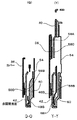
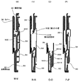
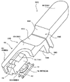
図34は図2のAA線断面図、図35は図2のBB線断面図、図36は外側部材64の一部を破断した望遠スイッチ30Dの要部を示す斜視図、図37は内側部材66と電気接片62の位置関係を示す斜視図である。なお、図36においては図面の簡略化を図るため外側部材64の形状の一部を省略した。
図2に示すように、筐体12の後面16の上部左側部寄りに、上下に縦長の切り欠き73が設けられ、この切り欠き73に望遠スイッチ30Dと広角スイッチ30Eとが上下に並べられて設けられている。
Next, the main part of the present invention will be described.
34 is a sectional view taken along line AA in FIG. 2, FIG. 35 is a sectional view taken along line BB in FIG. 2, FIG. 36 is a perspective view showing a main part of the telephoto switch 30D with a part of the outer member 64 broken, and FIG. It is a perspective view which shows the positional relationship of 66 and the electrical contact piece 62. FIG. In FIG. 36, a part of the shape of the outer member 64 is omitted in order to simplify the drawing.
As shown in FIG. 2, a vertically long cutout 73 is provided on the top left side of the rear surface 16 of the housing 12, and a telephoto switch 30 </ b> D and a wide-angle switch 30 </ b> E are vertically arranged in the cutout 73. Is provided.

望遠スイッチ30Dと広角スイッチ30Eは、図34、図35に示すように、筐体12の後面16に設けられた操作部材60を有し、操作部材60の押圧操作により筐体12の内部に設けられた電気接片62の接離を行うものである。本実施の形態では望遠スイッチ30Dと広角スイッチ30Eが本発明に係る操作装置を構成し、上側の操作部材60が望遠用操作部材60となり、下側の操作部材60が広角用操作部材60となっている。
電気接片62は、操作部材60により押圧される被押圧面62Aが、操作部材60が押圧される方向に対して斜めに配置されている。
詳細に説明すると、電気接片62は、筐体12内部に取着されたプリント基板63に実装され、被押圧面62Aはプリント基板63と平行し、したがって、プリント基板63も操作部材60が押圧される方向に対して斜めに配置されている。
また、図34に示すように、プリント基板63と、後述する外側部材64および内側部材66は、筐体12の左側部寄りの箇所の角部のデッドスペースに配置されている。
As shown in FIGS. 34 and 35, the telephoto switch 30D and the wide-angle switch 30E have an operation member 60 provided on the rear surface 16 of the housing 12, and are provided inside the housing 12 by a pressing operation of the operation member 60. The electrical contact piece 62 is contacted and separated. In the present embodiment, the telephoto switch 30D and the wide-angle switch 30E constitute the operating device according to the present invention, the upper operating member 60 becomes the telescopic operating member 60, and the lower operating member 60 becomes the wide-angle operating member 60. ing.
In the electrical contact piece 62, a pressed surface 62 </ b> A pressed by the operation member 60 is disposed obliquely with respect to the direction in which the operation member 60 is pressed.
More specifically, the electrical contact piece 62 is mounted on the printed circuit board 63 attached to the inside of the housing 12, and the pressed surface 62A is parallel to the printed circuit board 63. Therefore, the operation member 60 also presses the printed circuit board 63. It is arrange | positioned diagonally with respect to the direction made.
As shown in FIG. 34, the printed circuit board 63, an outer member 64 and an inner member 66 described later are disposed in a dead space at a corner near the left side of the housing 12.

操作部材60は、図34乃至図36に示すように、外側部材64と、内側部材66とを含んで構成されている。
各操作部材60の外側部材64は細長形状に形成され、それらの長手方向が同一直線上に位置するように配置され、互いに向かい合う長手方向の一端を支点として揺動可能に配設されている。
本実施の形態では、操作部材60は後面16の上部左側部にそれらの長手方向が上下に延在する同一直線上に位置するように並べられて設けられている。
外側部材64は、操作部68と、係合部70と、ストッパ部72とを含んで構成されている。
外側部材64は、合成樹脂製で型により一体成形されている。
As shown in FIGS. 34 to 36, the operation member 60 includes an outer member 64 and an inner member 66.
The outer member 64 of each operation member 60 is formed in an elongated shape, and is arranged so that the longitudinal directions thereof are located on the same straight line, and is arranged so as to be swingable with one end in the longitudinal direction facing each other as a fulcrum.
In the present embodiment, the operation members 60 are arranged on the upper left side of the rear surface 16 so that their longitudinal directions are positioned on the same straight line extending vertically.
The outer member 64 includes an operation part 68, an engagement part 70, and a stopper part 72.
The outer member 64 is made of synthetic resin and is integrally formed with a mold.

操作部68は、図35、図36に示すように、細長形状の板部68Aと、板部68Aの端部から屈曲する屈曲部68Bとを有し、屈曲部68Bの先端の凸部68Cは、筐体12側の凹部74(図35)に係合し、この凸部68Cと凹部74とが係合する箇所を支点として外側部材64は揺動する。より詳細には、各操作部材60の外側部材64は、互いに向かい合う長手方向の一端を、筐体12の左右方向に延在する軸心を支点として揺動可能に配設されている。
板部68Aは、筐体12の後面16(表面)に露出して配設され、この板部68Aは押圧操作される箇所となる。
係合部70は、内側部材66が係合する箇所であり、板部68Aが筐体12の内部に位置する箇所に設けられている。
係合部70は、凹状の係合凹部70Aとして形成されている。
係合凹部70Aは、外側部材64の長手方向に沿って細長形状に形成されている。
ストッパ部72は、図34、図35に示すように、操作部68に設けられ切り欠き73の周囲の筐体12内面に係止して筐体12の後面16(表面)における操作部68の最大突出位置を規制するものである。
As shown in FIGS. 35 and 36, the operating portion 68 has an elongated plate portion 68A and a bent portion 68B bent from the end portion of the plate portion 68A, and the convex portion 68C at the tip of the bent portion 68B is The outer member 64 oscillates by engaging with the concave portion 74 (FIG. 35) on the housing 12 side, and using the portion where the convex portion 68C and the concave portion 74 are engaged as a fulcrum. More specifically, the outer member 64 of each operation member 60 is disposed so as to be able to swing with one end in the longitudinal direction facing each other as an axis extending in the left-right direction of the housing 12.
The plate portion 68A is disposed so as to be exposed on the rear surface 16 (front surface) of the housing 12, and the plate portion 68A is a place to be pressed.
The engaging portion 70 is a location where the inner member 66 is engaged, and the plate portion 68 </ b> A is provided at a location located inside the housing 12.
The engaging portion 70 is formed as a concave engaging concave portion 70A.
The engaging recess 70 </ b> A is formed in an elongated shape along the longitudinal direction of the outer member 64.
As shown in FIGS. 34 and 35, the stopper portion 72 is provided on the operation portion 68 and is locked to the inner surface of the housing 12 around the notch 73 so that the operation portion 68 on the rear surface 16 (front surface) of the housing 12 is engaged. It regulates the maximum protruding position.

内側部材66は、図36、図37に示すように、本体部76と、押圧用凸部78と、ヒンジ部80とを有している。
内側部材66は、合成樹脂製で型により一体成形されている。
本体部76は、外側部材64に係合し外側部材64が押圧操作された際に押圧操作される方向に沿って移動される。
本体部76は、図35、図36に示すように、係合凹部70Aに挿入可能で係合凹部70Aの長手方向に沿った細長形状の板部82と、係合凹部70Aの底面に臨む板部82の面から突設され前記底面に係合する湾曲面部84とを備えている。なお、湾曲面部84を備えることにより、外側部材64が押圧操作された際に、係合凹部70Aの底面に対して湾曲面部84が係合することにより内側部材66が円滑に移動するように図られている。
押圧用凸部78が被押圧面62Aに押圧する箇所は、被押圧面62A側に凸状の湾曲面で形成され、被押圧面62Aへの押圧が円滑に行われるように図られている。
押圧用凸部78は、本体部76から被押圧面62Aに対して直交するように突設され、したがって、押圧用凸部78は、図34に示すように、本体部76から斜めに突設されている。
ヒンジ部80は、本体部76から突設され筐体12の内部の箇所に係止され弾性変形可能である。
押圧用凸部78とヒンジ部80とは、本体部76から互いに反対の向きに突出している。
ヒンジ部80は、外側部材64を筐体12の表面から突出する方向に常時付勢すると共に、外側部材64が押圧された際に弾性変形して本体部76の移動を許容し押圧用凸部78による被押圧面62Aの押圧を許容するように形成されている。
本実施の形態では、ヒンジ部80は、本体部76から突出する2本の脚部80Aと、それら脚部80Aの先端を接続する接続部80Bとで構成され、図34に示すように、接続部80Bが筐体12側の凹部に係止される。
そして、内側部材66は、ヒンジ部80の接続部80B部分を支点として揺動し、言い換えると、内側部材66は、筐体12の上下方向に延在する軸心を支点として揺動する。
As shown in FIGS. 36 and 37, the inner member 66 includes a main body portion 76, a pressing convex portion 78, and a hinge portion 80.
The inner member 66 is made of synthetic resin and is integrally formed with a mold.
The main body 76 is moved along the direction in which the outer member 64 is pressed and operated when the outer member 64 is pressed.
As shown in FIGS. 35 and 36, the main body 76 includes an elongated plate portion 82 that can be inserted into the engagement recess 70A and extends in the longitudinal direction of the engagement recess 70A, and a plate that faces the bottom surface of the engagement recess 70A. A curved surface portion 84 protruding from the surface of the portion 82 and engaging with the bottom surface. The curved surface portion 84 is provided so that when the outer member 64 is pressed, the inner surface 66 moves smoothly by engaging the curved surface portion 84 with the bottom surface of the engaging recess 70A. It has been.
The portion where the pressing convex portion 78 presses against the pressed surface 62A is formed as a convex curved surface on the pressed surface 62A side so that the pressing to the pressed surface 62A is performed smoothly.
The pressing convex portion 78 protrudes from the main body portion 76 so as to be orthogonal to the pressed surface 62A. Therefore, the pressing convex portion 78 protrudes obliquely from the main body portion 76 as shown in FIG. Has been.
The hinge portion 80 protrudes from the main body portion 76, is locked at a location inside the housing 12, and can be elastically deformed.
The pressing convex part 78 and the hinge part 80 protrude from the main body part 76 in directions opposite to each other.
The hinge portion 80 constantly urges the outer member 64 in a direction protruding from the surface of the housing 12 and is elastically deformed when the outer member 64 is pressed to allow the main body portion 76 to move and press convex portion. It is formed so as to allow pressing of the pressed surface 62 </ b> A by 78.
In the present embodiment, the hinge portion 80 includes two leg portions 80A protruding from the main body portion 76 and a connection portion 80B that connects the tips of the leg portions 80A. As shown in FIG. The portion 80B is locked in the recess on the housing 12 side.
The inner member 66 swings with the connecting portion 80B portion of the hinge portion 80 as a fulcrum, in other words, the inner member 66 swings with an axis extending in the vertical direction of the housing 12 as a fulcrum.

次に動作について説明する。
望遠用操作部材60または広角用操作部材60を指によりヒンジ部80の付勢力に抗して押圧操作すると、外側部材64が揺動し、これにより内側部材66がヒンジ部80を介して揺動し、押圧用凸部78が被押圧面62Aを押圧し電気接片62がオンされる。これにより、望遠スイッチ30Dあるいは広角スイッチ30Eから操作信号が制御部34に供給され、これによりズーミング動作がなされる。
外側部材64から指を離すと、ヒンジ部80の付勢力によって外側部材64は内側部材66と共に筐体12の後面16から後方に突出する方向に揺動し、ストッパ部72が切り欠き73の周囲の筐体12内面に係止し、外側部材64は最大突出位置となる。
これにより、押圧用凸部78による被押圧面62Aの押圧が解除され電気接片62がオフされ、望遠スイッチ30Dあるいは広角スイッチ30Eからの操作信号の制御部34への供給が停止され、これによりズーミング動作が停止される。
Next, the operation will be described.
When the telescopic operation member 60 or the wide-angle operation member 60 is pressed with a finger against the urging force of the hinge portion 80, the outer member 64 swings, whereby the inner member 66 swings via the hinge portion 80. Then, the pressing projection 78 presses the pressed surface 62A, and the electrical contact piece 62 is turned on. Accordingly, an operation signal is supplied from the telephoto switch 30D or the wide-angle switch 30E to the control unit 34, thereby performing a zooming operation.
When the finger is released from the outer member 64, the outer member 64 swings together with the inner member 66 in a direction protruding rearward from the rear surface 16 of the housing 12 due to the biasing force of the hinge portion 80, and the stopper portion 72 is surrounded by the notch 73. The outer member 64 is locked to the inner surface of the casing 12 and is in the maximum protruding position.
Thereby, the pressing of the pressed surface 62A by the pressing convex part 78 is released, the electric contact piece 62 is turned off, and the supply of the operation signal from the telephoto switch 30D or the wide-angle switch 30E to the control unit 34 is stopped. Zooming operation is stopped.

本実施の形態によれば、電気接片62は、望遠用操作部材60または広角用操作部材60により押圧される被押圧面62Aが、操作部材60が押圧される方向に対して斜めに配置されているので、電気接片62およびプリント基板63の筐体12の後面16(表面)に対する電気接片62およびプリント基板63の投影面積を縮小でき、したがって、筐体12の幅方向のスペースを縮小して小型化を図る上で有利となる。
また、本実施の形態では、筐体12の左側部寄りの箇所の角部のデッドスペースに外側部材64および内側部材66並びにプリント基板63を配置したので、筐体12内部のスペースを有効に活用でき、小型化を図る上でより有利となる。
また、本実施の形態では、外側部材64が筐体12の左右方向に延在する軸心を支点に揺動し、かつ、内側部材66が筐体12の上下方向に延在する軸心を支点に揺動し、それら支点が異なった箇所に位置することから、狭いデッドスペースに外側部材64および内側部材66を配置する上で有利となる。
また、本実施の形態では、内側部材66の押圧用凸部78が本体部76に対して斜めに突設されているので、押圧用凸部78の移動量に対して外側部材64および内側部材66の移動量が大きなものとなり、したがって、電気接片62を接離させるために要する内側部材66による電気接片62の押し込み量に対して、外側部材64のストロークを大きな寸法として確保することができる。
そのため、電気接片62の押し込み量が比較的短い場合であっても外側部材64のストロークを大きく確保することで外側部材64をしっかり押し込んだ感触をユーザに与えることができ、操作性の向上を図る上で有利となる。
According to the present embodiment, the electrical contact piece 62 is disposed such that the pressed surface 62A pressed by the telescopic operating member 60 or the wide-angle operating member 60 is inclined with respect to the direction in which the operating member 60 is pressed. Therefore, the projected area of the electrical contact piece 62 and the printed circuit board 63 on the rear surface 16 (front surface) of the electrical contact piece 62 and the printed circuit board 63 can be reduced, and therefore the space in the width direction of the housing 12 is reduced. Thus, it is advantageous for downsizing.
In the present embodiment, since the outer member 64, the inner member 66, and the printed circuit board 63 are disposed in the dead space at the corner near the left side of the housing 12, the space inside the housing 12 is effectively utilized. This is advantageous for downsizing.
Further, in the present embodiment, the outer member 64 swings around the axis extending in the left-right direction of the casing 12 and the inner member 66 has the axis extending in the vertical direction of the casing 12. Since it swings to a fulcrum and these fulcrums are located at different locations, it is advantageous in arranging the outer member 64 and the inner member 66 in a narrow dead space.
Further, in the present embodiment, the pressing convex portion 78 of the inner member 66 protrudes obliquely with respect to the main body portion 76, so the outer member 64 and the inner member with respect to the movement amount of the pressing convex portion 78. Therefore, the stroke of the outer member 64 can be secured as a large dimension with respect to the pushing amount of the electric contact piece 62 by the inner member 66 required for moving the electric contact piece 62 in and out of contact with each other. it can.
Therefore, even when the pushing amount of the electrical contact piece 62 is relatively short, by ensuring a large stroke of the outer member 64, it is possible to give the user a feeling that the outer member 64 has been pushed in firmly, improving operability. It is advantageous in planning.

また、本実施の形態では、図36に示すように、2つの外側部材64を同一直線上に位置するように配置し、2つの外側部材64の板部68Aが互いに近接する箇所を支点としてそれら外側部材64が揺動するように構成し、さらに、それら外側部材64が互いに近接する箇所に凹部68Dをそれぞれ設け、それら凹部68Dにより単一の凹部68Eが構成されるようにした。
そのため、凹部68Eに指を当て付けた状態では、指でくぼみ部68Eを押圧したとしても、外側部材64の押圧操作が不用意になされることがないため、各外側部材64の誤操作を防止する上で有利となっている。
また、くぼみ部68Eに当て付けた指を外側部材64の延在方向に沿ってずらすことによって2つの外側部材64のうちの一方の押圧操作が即座に可能となり、その際、指の位置をいちいち視認する必要が無いため、操作性の向上を図る上で有利となっている。
In the present embodiment, as shown in FIG. 36, the two outer members 64 are arranged so as to be located on the same straight line, and the portions where the plate portions 68A of the two outer members 64 are close to each other serve as fulcrums. The outer member 64 is configured to swing, and the recesses 68D are provided at locations where the outer members 64 are close to each other, and the recesses 68D constitute a single recess 68E.
Therefore, in the state where the finger is applied to the concave portion 68E, even if the depressed portion 68E is pressed with the finger, the pressing operation of the outer member 64 is not inadvertently performed, so that erroneous operation of each outer member 64 is prevented. It is advantageous in the above.
Also, by pressing the finger applied to the indented portion 68E along the extending direction of the outer member 64, one of the two outer members 64 can be immediately pressed, and the position of the finger is changed each time. Since there is no need for visual recognition, it is advantageous in improving operability.

また、特に、本実施の形態のようなデジタルスチルカメラにおいては、筐体12の外形寸法を変えることなく後面16に配置されるディスプレイ32の表示面をより大きく確保することが求められている。そのため、ディスプレイ32を除く後面16部分のスペースが縮小される傾向にあり、狭いスペースに操作装置を配置せざるを得ないのが現状である。
これに対して本発明に係る操作装置によれば、上述したように操作装置の占有スペースが少なく、しかも、操作装置のデッドスペースへの配置が容易であることから、操作装置を筐体12の後面16と左側面20との稜線に近接させて配設することができ、操作装置を筐体12の後面16における限られたスペースに配置する上で極めて有利となる。
In particular, in the digital still camera as in the present embodiment, it is required to secure a larger display surface of the display 32 disposed on the rear surface 16 without changing the external dimensions of the housing 12. For this reason, the space of the rear surface 16 portion excluding the display 32 tends to be reduced, and the operating device must be arranged in a narrow space at present.
On the other hand, according to the operating device according to the present invention, as described above, the operating device occupies less space, and the operating device can be easily placed in the dead space. It can be arranged close to the ridgeline between the rear surface 16 and the left side surface 20, which is extremely advantageous in arranging the operating device in a limited space on the rear surface 16 of the housing 12.

なお、実施の形態では、電子機器が撮像装置10であり撮像装置10がデジタルスチルカメラである場合について説明したが、本発明は、ビデオカメラ、携帯電話機、PDA、音楽プレーヤー、ノート型パーソナルコンピュータなどさまざまな電子機器に適用可能である。   Note that although cases have been described with the embodiments where the electronic device is the imaging device 10 and the imaging device 10 is a digital still camera, the present invention is not limited to a video camera, a mobile phone, a PDA, a music player, a notebook personal computer, or the like. Applicable to various electronic devices.

(A)は本実施の形態の撮像装置10のカバー36が閉塞位置P1P1にある状態を示す斜視図、(B)は撮像装置10のカバー36が開放位置P2にある状態を示す斜視図である。(A) is a perspective view which shows the state in which the cover 36 of the imaging device 10 of this Embodiment exists in the obstruction | occlusion position P1P1, (B) is a perspective view which shows the state in which the cover 36 of the imaging device 10 exists in the open position P2. . 撮像装置10を後方から見た斜視図である。It is the perspective view which looked at the imaging device 10 from back. 撮像装置10の構成を示すブロック図である。1 is a block diagram illustrating a configuration of an imaging device 10. FIG. 筐体12の前面部分およびカバー36の分解斜視図である。3 is an exploded perspective view of a front surface portion of a housing 12 and a cover 36. FIG. 筐体12の前面部分およびカバー36の分解斜視図である。3 is an exploded perspective view of a front surface portion of a housing 12 and a cover 36. FIG. 筐体12の前面部分を後方から見た斜視図である。It is the perspective view which looked at the front part of case 12 from back. 筐体12の前面部分の後方に臨む面がフィルム54で覆われた状態を示す斜視図である。6 is a perspective view showing a state in which a surface facing the rear of the front surface portion of the housing 12 is covered with a film 54. FIG. インナーキャビネット50の後方に配置されるレンズ鏡筒26や電子部品27がインナーキャビネット50に臨む面がフィルム54で覆われた状態を示す斜視図である。FIG. 3 is a perspective view showing a state in which a lens barrel 26 and an electronic component 27 arranged behind the inner cabinet 50 face the inner cabinet 50 and are covered with a film 54. 筐体12の前面部分からアウターキャビネット46を除いて前方から見た斜視図である。FIG. 5 is a perspective view seen from the front, excluding the outer cabinet 46 from the front surface portion of the housing 12. 筐体12の前面部分からアウターキャビネット46を除いて前方から見た斜視図である。FIG. 5 is a perspective view seen from the front, excluding the outer cabinet 46 from the front surface portion of the housing 12. 図10のA部拡大斜視図である。It is the A section expansion perspective view of FIG. 筐体12の前面部分からアウターキャビネット46を除いて前方から見た斜視図である。FIG. 5 is a perspective view seen from the front, excluding the outer cabinet 46 from the front surface portion of the housing 12. 図10のA部拡大斜視図である。It is the A section expansion perspective view of FIG. (A)はカバー36が閉塞位置P1に位置した状態を示す正面図、(B)は図14(A)のB矢視図、(C)は図14(A)のC矢視図である。(A) is a front view showing a state in which the cover 36 is located at the closing position P1, (B) is a view as seen from the arrow B in FIG. 14 (A), (C) is a view as seen from the arrow C in FIG. 14 (A). . (T)は図14(A)のTT線断面図、(U)は図14(A)のUU線断面図、(V)は図14(A)のVV線断面図である。(T) is a cross-sectional view taken along line TT in FIG. 14 (A), (U) is a cross-sectional view taken along line UU in FIG. 14 (A), and (V) is a cross-sectional view taken along line VV in FIG. (W)は図14(A)のWW線断面図、(X)は図14(A)のXX線断面図である。(W) is a cross-sectional view taken along line WW in FIG. 14 (A), and (X) is a cross-sectional view taken along line XX in FIG. 14 (A). (A)はカバー36が閉塞位置P1に位置した状態を前方から見たインナーキャビネット50、スライダプレート48の位置関係を示す正面図、(B)はカバー36が閉塞位置P1に位置した状態を後方から見たインナーキャビネット50、スライダプレート48の位置関係を示す背面図である。(A) is a front view showing the positional relationship between the inner cabinet 50 and the slider plate 48 when the cover 36 is located at the closed position P1 from the front, and (B) is the rear view when the cover 36 is located at the closed position P1. It is a rear view which shows the positional relationship of the inner cabinet 50 and the slider plate 48 seen from. (A)はカバー36が閉塞位置P1から開放位置P2に向けて移動しつつある状態を示す正面図、(B)は図18(A)のB矢視図、(C)は図18(A)のC矢視図である。(A) is a front view which shows the state which the cover 36 is moving toward the open position P2 from the obstruction | occlusion position P1, (B) is a B arrow view of FIG. 18 (A), (C) is FIG. ) Is a C arrow view. (F)は図18(A)のFF線断面図、(G)は図18(A)のGG線断面図、(I)は図18(A)のII線断面図である。18F is a cross-sectional view taken along line FF in FIG. 18A, FIG. 18G is a cross-sectional view taken along line GG in FIG. 18A, and FIG. 18I is a cross-sectional view taken along line II in FIG. (R)は図18(A)のRR線断面図、(S)は図18(A)のSS線断面図である。(R) is a cross-sectional view taken along line RR in FIG. 18 (A), and (S) is a cross-sectional view taken along line SS in FIG. 18 (A). (A)はカバー36が閉塞位置P1から開放位置P2に向けて移動しつつある状態を前方から見たインナーキャビネット50、スライダプレート48の位置関係を示す正面図、(B)はカバー36が閉塞位置P1から開放位置P2に向けて移動した状態を後方から見たインナーキャビ50、スライダプレート48の位置関係を示す背面図である。(A) is a front view showing the positional relationship between the inner cabinet 50 and the slider plate 48 when the cover 36 is moving from the closed position P1 toward the open position P2 as viewed from the front. FIG. 7 is a rear view showing the positional relationship between the inner cavity 50 and the slider plate 48 as viewed from the rear in a state of moving from the position P1 toward the open position P2. FIG. (A)はカバー36が後方に向けて押圧されつつ閉塞位置P1から開放位置P2に向けて移動しつつある状態を示す正面図、(B)は図22(A)のB矢視図、(C)は図22(A)のC矢視図である。(A) is a front view showing a state in which the cover 36 is moving from the closed position P1 toward the open position P2 while being pressed backward, and (B) is a view as viewed in the direction of arrow B in FIG. C) is a C arrow view of FIG. (J)は図22(A)のJJ線断面図、(K)は図22(A)のKK線断面図、(L)は図22(A)のLL線断面図である。FIG. 22J is a sectional view taken along the line JJ in FIG. 22A, FIG. 22K is a sectional view taken along the line KK in FIG. 22A, and FIG. 22L is a sectional view taken along the line LL in FIG. (A)はカバー36が開放位置P2に位置した状態を示す正面図、(B)は図24(A)のB矢視図、(C)は図24(A)のC矢視図である。(A) is a front view showing a state in which the cover 36 is located at the open position P2, (B) is a view as seen from the arrow B in FIG. 24 (A), (C) is a view as seen from the arrow C in FIG. . (D)は図24(A)のDD線断面図、(E)は図24(A)のEE線矢視図、(H)は図24(A)のHH線断面図である。24D is a sectional view taken along the line DD in FIG. 24A, FIG. 24E is a sectional view taken along the line EE in FIG. 24A, and FIG. 25H is a sectional view taken along the line HH in FIG. (Q)は図24(A)のQQ線断面図であり、(Y)は図24(A)のYY線断面図である。(Q) is a cross-sectional view taken along the line QQ in FIG. 24A, and (Y) is a cross-sectional view taken along the line YY in FIG. (A)はカバー36が開放位置P2に位置した状態を前方から見たインナーキャビネット50、スライダプレート48の位置関係を示す正面図、(B)はカバー36が開放位置P2に位置した状態を後方から見たインナーキャビネット50、スライダプレート48の位置関係を示す背面図である。(A) is a front view showing the positional relationship between the inner cabinet 50 and the slider plate 48 when the cover 36 is located at the open position P2 from the front, and (B) is the rear view when the cover 36 is located at the open position P2. It is a rear view which shows the positional relationship of the inner cabinet 50 and the slider plate 48 seen from. (A)はカバー36が閉塞位置P1の直前に位置した状態を示す正面図、(B)は図28(A)のB矢視図、(C)は図22(A)のC矢視図である。(A) is a front view showing a state in which the cover 36 is located immediately before the closing position P1, (B) is a view as seen from the arrow B in FIG. 28 (A), (C) is a view as seen from the arrow C in FIG. It is. (M)は図28(A)のMM線断面図、(N)は図28(A)のNN線断面図、(O)は図28(A)のOO線断面図、(P)は図28(A)PP線断面図である。(M) is a cross-sectional view taken along line MM in FIG. 28 (A), (N) is a cross-sectional view taken along line NN in FIG. 28 (A), (O) is a cross-sectional view taken along line OO in FIG. It is 28 (A) PP sectional view. (A)はアウターキャビネット46の斜視図、(B)はアウターキャビネット46の前後を反転した斜視図である。(A) is a perspective view of the outer cabinet 46, and (B) is a perspective view in which the front and rear of the outer cabinet 46 are reversed. (A)はインナーキャビネット50の斜視図、(B)はインナーキャビネット50の前後を反転した斜視図、(C)は図31(A)のC部分の拡大斜視図である。(A) is the perspective view of the inner cabinet 50, (B) is the perspective view which reversed the front and rear of the inner cabinet 50, (C) is the expansion perspective view of C section of FIG. 31 (A). (A)、(B)はフレーム44の斜視図、(C)は図32(A)のC矢視図である。(A), (B) is a perspective view of the frame 44, (C) is a C arrow line view of FIG. 32 (A). (A)はスライダプレート48の斜視図、(B)はスライダプレート48の前後を反転した斜視図である。(A) is a perspective view of the slider plate 48, and (B) is a perspective view in which the front and rear of the slider plate 48 are reversed. 図2のAA線断面図である。FIG. 3 is a sectional view taken along line AA in FIG. 2. 図2のBB線断面図である。It is BB sectional drawing of FIG. 外側部材64の一部を破断した望遠スイッチ30Dの要部を示す斜視図である。It is a perspective view which shows the principal part of telephoto switch 30D which fractured | ruptured a part of outer member 64. FIG. 内側部材66と電気接片62の位置関係を示す斜視図である。6 is a perspective view showing a positional relationship between an inner member 66 and an electrical contact piece 62. FIG.

符号の説明Explanation of symbols

10……撮像装置、12……筐体、16……後面、30D……望遠スイッチ、30E……広角スイッチ、60……操作部材、62……電気接片、62A……被押圧面、64……外側部材、66……内側部材、76……本体部、78……押圧用凸部、80……ヒンジ部。   DESCRIPTION OF SYMBOLS 10 ... Imaging device, 12 ... Housing, 16 ... Rear surface, 30D ... Telephoto switch, 30E ... Wide-angle switch, 60 ... Operation member, 62 ... Electrical contact piece, 62A ... Pressed surface, 64 …… Outer member, 66 …… Inner member, 76 …… Main body, 78 …… Pressing convex portion, 80 …… Hinge portion.

Claims (10)

筐体の表面に設けられた操作部材の押圧操作により前記筐体の内部に設けられた電気接片の接離を行なう操作装置を備えた電子機器であって、
前記電気接片は、前記操作部材により押圧される被押圧面が、前記操作部材が押圧される方向に対して斜めに配置され、
前記操作部材は、前記筐体の表面に露出し押圧操作される外側部材と、前記外側部材と前記電気接片との間に配置された内側部材とを含んで構成され、
前記内側部材は、前記外側部材に係合し前記外側部材が押圧操作された際に前記押圧操作される方向に沿って移動される本体部と、前記本体部から前記被押圧面に対して直交するように突設された押圧用凸部と、前記本体部から突設され前記筐体の内部の箇所に係止される弾性変形可能なヒンジ部とを有し、
前記ヒンジ部は、前記外側部材を前記筐体の表面から突出する方向に常時付勢すると共に、前記外側部材が押圧された際に弾性変形して前記本体部の移動を許容し前記押圧用凸部による前記被押圧面の押圧を許容する、
ことを特徴とする電子機器。
An electronic device including an operation device that performs contact and separation of an electrical contact piece provided inside the housing by a pressing operation of an operation member provided on a surface of the housing,
The electric contact piece is arranged such that a pressed surface pressed by the operation member is inclined with respect to a direction in which the operation member is pressed,
The operation member includes an outer member that is exposed and pressed on the surface of the housing, and an inner member that is disposed between the outer member and the electrical contact piece,
The inner member is engaged with the outer member and moved along the direction of pressing when the outer member is pressed, and orthogonal to the pressed surface from the main body. A pressing convex portion protruding so as to perform, and an elastically deformable hinge portion protruding from the main body portion and locked to a position inside the casing,
The hinge portion constantly urges the outer member in a direction protruding from the surface of the housing, and elastically deforms when the outer member is pressed to allow the main body portion to move, thereby allowing the pressing protrusion. Allowing the pressed surface to be pressed by the part,
An electronic device characterized by that.
前記押圧用凸部と前記ヒンジ部とは、前記本体部から互いに反対の向きに突出している、
ことを特徴とする請求項1記載の電子機器。
The pressing convex portion and the hinge portion protrude in opposite directions from the main body portion,
The electronic device according to claim 1.
前記押圧用凸部が前記被押圧面に押圧する箇所は、前記被押圧面側に凸状の湾曲面で形成されている、
ことを特徴とする請求項1記載の電子機器。
The portion where the pressing convex portion presses against the pressed surface is formed of a convex curved surface on the pressed surface side.
The electronic device according to claim 1.
前記内側部材は、合成樹脂製で型により一体成形されている、
ことを特徴とする請求項1記載の電子機器。
The inner member is made of synthetic resin and integrally formed with a mold.
The electronic device according to claim 1.
前記外側部材は、前記筐体の表面に露出して押圧操作される操作部と、前記操作部が前記筐体の内部に位置する箇所に設けられ前記本体部が係合する係合部と、前記操作部に設けられ前記筐体側に係止して前記筐体の表面における前記操作部の最大突出位置を規制するストッパ部とを含んで構成されている、
ことを特徴とする請求項1記載の電子機器。
The outer member is an operation unit that is exposed and pressed on the surface of the housing; an engagement unit that is provided at a position where the operation unit is located inside the housing; A stopper portion that is provided on the operation portion and is locked to the housing side to restrict the maximum protruding position of the operation portion on the surface of the housing;
The electronic device according to claim 1.
前記係合部は、凹状の係合凹部として形成され、
前記本体部は、前記係合凹部に挿入され前記係合凹部の底面に係合する前記底面側に凸状の湾曲面部を含んで構成されている、
ことを特徴とする請求項5記載の電子機器。
The engagement portion is formed as a concave engagement recess,
The main body is configured to include a convex curved surface portion on the bottom surface side that is inserted into the engagement recess and engages with the bottom surface of the engagement recess.
6. The electronic apparatus according to claim 5, wherein
前記外側部材は細長形状に形成され、
前記外側部材は、長手方向の一端を支点として揺動可能に配設され、
前記係合部は、凹状の係合凹部として形成され、
前記係合凹部は、前記外側部材の長手方向に沿って細長形状に形成され、
前記本体部は、前記係合凹部に挿入可能で係合凹部の長手方向に沿った細長形状の板部と、前記係合凹部の底面に臨む前記板部の箇所から突設され前記底面に係合する湾曲面部とを備えている、
ことを特徴とする請求項5記載の電子機器。
The outer member is formed in an elongated shape,
The outer member is disposed so as to be swingable with one end in the longitudinal direction as a fulcrum,
The engagement portion is formed as a concave engagement recess,
The engaging recess is formed in an elongated shape along the longitudinal direction of the outer member,
The main body is protruded from an elongated plate portion that can be inserted into the engagement recess and extends in the longitudinal direction of the engagement recess, and a portion of the plate that faces the bottom surface of the engagement recess, and is engaged with the bottom surface. A curved surface portion to be joined,
6. The electronic apparatus according to claim 5, wherein
前記電気接片は、前記筐体の内部に設けられたプリント基板上に設けられ、
前記被押圧面は前記プリント基板と平行している、
ことを特徴とする請求項1記載の電子機器。
The electrical contact piece is provided on a printed circuit board provided inside the housing,
The pressed surface is parallel to the printed circuit board;
The electronic device according to claim 1.
前記電気接片および操作部材はそれぞれ2つずつ設けられ、
各操作部材の前記外側部材は細長形状に形成され、それらの長手方向が同一直線上に位置するように配置され、
各操作部材の前記外側部材は、互いに向かい合う長手方向の一端を支点として揺動可能に配設されている、
ことを特徴とする請求項5記載の電子機器。
Two each of the electric contact piece and the operation member are provided,
The outer member of each operation member is formed in an elongated shape, and is arranged so that their longitudinal directions are located on the same straight line,
The outer member of each operation member is disposed so as to be swingable with one end in the longitudinal direction facing each other as a fulcrum,
6. The electronic apparatus according to claim 5, wherein
前記電子機器は撮像装置であり、
前記筐体は対物レンズが設けられた前面と、ディスプレイが設けられた後面とを有して矩形板状に形成され、
前記電気接片および前記操作部材は望遠ズーム操作用および広角ズーム操作用としてそれぞれ2つずつ設けられ、
前記操作部材は前記後面の上部左側部にそれらの長手方向が上下に延在する同一直線上に位置するように並べられて設けられ、
各操作部材の前記外側部材は、互いに向かい合う長手方向の一端を、前記筐体の左右方向に延在する軸心を支点として揺動可能に配設され、
各操作部材の前記内側部材は、前記筐体の上下方向に延在する軸心を支点として揺動可能に配設されている、
ことを特徴とする請求項5記載の電子機器。
The electronic device is an imaging device;
The housing has a front surface provided with an objective lens and a rear surface provided with a display, and is formed in a rectangular plate shape.
Two each of the electric contact piece and the operation member are provided for telephoto zoom operation and wide-angle zoom operation,
The operating members are arranged on the upper left side of the rear surface so that their longitudinal directions are positioned on the same straight line extending vertically,
The outer member of each operation member is disposed so as to be able to swing with one end in the longitudinal direction facing each other about an axis extending in the left-right direction of the housing as a fulcrum,
The inner member of each operation member is disposed so as to be swingable about an axis extending in the vertical direction of the casing.
6. The electronic apparatus according to claim 5, wherein
JP2007270036A 2007-10-17 2007-10-17 Electronic apparatus Pending JP2009100268A (en)

Priority Applications (1)

Application Number Priority Date Filing Date Title
JP2007270036A JP2009100268A (en) 2007-10-17 2007-10-17 Electronic apparatus

Applications Claiming Priority (1)

Application Number Priority Date Filing Date Title
JP2007270036A JP2009100268A (en) 2007-10-17 2007-10-17 Electronic apparatus

Publications (1)

Publication Number Publication Date
JP2009100268A true JP2009100268A (en) 2009-05-07

Family

ID=40702845

Family Applications (1)

Application Number Title Priority Date Filing Date
JP2007270036A Pending JP2009100268A (en) 2007-10-17 2007-10-17 Electronic apparatus

Country Status (1)

Country Link
JP (1) JP2009100268A (en)

Similar Documents

Publication Publication Date Title
TWI339063B (en) Image capturing apparatus
JP4842223B2 (en) Electronic equipment and slide module
JP2009098415A (en) Electronic device
US8063983B2 (en) Imaging apparatus having a movable barrier and a movable barrier opening/closing member
US8174846B2 (en) Electronic device
US9529441B2 (en) Display apparatus
US8085343B2 (en) Image capture apparatus
US8412265B2 (en) Electronic apparatus with photographing functions
WO2011065472A1 (en) Portable electronic device
US8395060B2 (en) Electronic device
JP4626818B2 (en) Electronics
JP2006317547A (en) Catoptric system assembling unit and imaging apparatus using same
JP4823803B2 (en) Slide switch device
JP2009100268A (en) Electronic apparatus
JP2009098413A (en) Electronic device
JP4591779B2 (en) Imaging device
US9417507B2 (en) Electronic apparatus
JP2012093955A (en) Portable electronic device
JP5466930B2 (en) Portable electronic devices
JP5466931B2 (en) Portable electronic devices
JP2007325009A (en) Image pick-up device
JP2009175282A (en) Imaging apparatus
JP2012141425A (en) Display device
JP2010027405A (en) Sliding operation device
JP2010102259A (en) Imaging device

Legal Events

Date Code Title Description
RD02 Notification of acceptance of power of attorney

Free format text: JAPANESE INTERMEDIATE CODE: A7422

Effective date: 20090819

RD04 Notification of resignation of power of attorney

Free format text: JAPANESE INTERMEDIATE CODE: A7424

Effective date: 20091016