JP2009097352A - Engine cooling system - Google Patents
Engine cooling system Download PDFInfo
- Publication number
- JP2009097352A JP2009097352A JP2007267083A JP2007267083A JP2009097352A JP 2009097352 A JP2009097352 A JP 2009097352A JP 2007267083 A JP2007267083 A JP 2007267083A JP 2007267083 A JP2007267083 A JP 2007267083A JP 2009097352 A JP2009097352 A JP 2009097352A
- Authority
- JP
- Japan
- Prior art keywords
- valve
- cooling water
- temperature
- thermostat
- passage
- Prior art date
- Legal status (The legal status is an assumption and is not a legal conclusion. Google has not performed a legal analysis and makes no representation as to the accuracy of the status listed.)
- Pending
Links
Images


Abstract
Description
本発明は、エンジンの冷却装置に関するものである。 The present invention relates to an engine cooling apparatus.
従来から、シリンダブロック及びシリンダヘッドにウォータジャケットをそれぞれ形成し、冷却水の温度が低いときはシリンダブロックのウォータジャケットを迂回してシリンダヘッドのウォータジャケットにのみ冷却水を流通させ、さらに、冷却水の温度が高くなるとラジエータを介して冷却水を循環させるエンジンの冷却装置が知られている(例えば、特許文献1及び2)。このエンジンの冷却装置によれば、冷間始動時にシリンダヘッドと冷却水との熱交換が積極的に行われることから、冷却水の早期昇温を図れるとともに、シリンダブロックのウォータジャケットには冷却水が流通しないことから、シリンダブロックのシリンダライナ温度を速やかに上昇させることができる。したがって、冷間始動時における暖機運転が速やかに完了するとともに、シリンダブロックにおける燃費の低減を図ることができる。
Conventionally, a water jacket is formed on each of the cylinder block and the cylinder head, and when the temperature of the cooling water is low, the cooling water is circulated only through the water jacket of the cylinder head, bypassing the water jacket of the cylinder block, and further, An engine cooling device that circulates cooling water through a radiator when the temperature of the engine becomes high is known (for example,
この種のエンジンの冷却装置は、ラジエータへの冷却水の流通を制御するメインサーモスタット弁とは別に、冷却水等の温度に応じてシリンダブロック又はシリンダヘッドのウォータジャケットへの冷却水の流通を切り換えるサブサーモスタット弁を備えており、冷却水等の温度が所定温度以上になるとこのサブサーモスタット弁が開弁し、冷却水がシリンダブロックのウォータジャケットへ流通するよう構成されている。これにより、昇温したシリンダブロックが過度に高温となることが抑制されるので、シリンダブロックにおけるオイル消費の増加や、シリンダライナの焼き付き等を抑制できる。 This type of engine cooling device switches the flow of cooling water to the cylinder block or the water jacket of the cylinder head according to the temperature of the cooling water, etc. separately from the main thermostat valve that controls the flow of cooling water to the radiator. A sub thermostat valve is provided, and the sub thermostat valve is opened when the temperature of the cooling water or the like exceeds a predetermined temperature, and the cooling water is circulated to the water jacket of the cylinder block. Thereby, since it is suppressed that the heated cylinder block becomes high temperature too much, the increase in the oil consumption in a cylinder block, the burning of a cylinder liner, etc. can be suppressed.
このようなサブサーモスタット弁として、例えば、特許文献1では電磁式のものが用いられているが、電磁式サーモスタット弁を用いると冷却装置のコストが嵩むとともに、回路のレイアウトが困難となることから、ワックス(熱膨張体)を内蔵したワックス・ペレット型サーモスタット弁(以下、単にサーモスタット弁という)が用いられることが多い。サーモスタット弁の基本的な構成は、以下の通りである。つまり、冷却水を流通させるための流通孔が形成された弁座と、ワックスが内蔵されるとともにスプリングが取り付けられた弁体とを備え、ワックスの膨張力により弁体を弁座から離れるように変位させて弁座との間の弁通路を開く一方、スプリングの付勢力により弁体を弁座に当接させて流通孔を塞ぐことで、弁の開閉を行うようになっている。
ところで、サーモスタット弁に内蔵されたワックスは所定の熱容量を有しているため、高温の冷却水に浸されても直ぐには膨張せず、それ自体が十分に暖まってから膨張し始めるという性質を有している。このため、上記エンジンの冷却装置では、サブサーモスタット弁に高温の冷却水が流入しても、サブサーモスタット弁は直ぐには開弁しないので、シリンダブロックの冷却要求に対して応答が遅れることがある。 By the way, since the wax built in the thermostat valve has a predetermined heat capacity, it does not expand immediately even if it is immersed in high-temperature cooling water, and has the property of starting to expand after it has sufficiently warmed itself. is doing. For this reason, in the engine cooling device, even when high-temperature cooling water flows into the sub thermostat valve, the sub thermostat valve does not open immediately, so that the response to the cylinder block cooling request may be delayed.
このようなワックスの特性は、例えば、エンジンをかけた後暖機運転が完了するまで低負荷運転する場合には、冷却水が徐々に昇温する過程でワックスも徐々に暖まり、冷却水の昇温にともなって開弁時の冷却水流量が変化することから問題とならない。しかしながら、例えば、高速道路においてサービスエリアで車両を駐車した後に本車線に合流する際など、エンジンをかけた後暖機運転が完了する前に高負荷高回転運転に移行する場合には、ワックスの特性に起因して以下の問題が生じる。 Such a characteristic of the wax is that, for example, in the case of low load operation until the warm-up operation is completed after starting the engine, the wax gradually warms in the process of gradually raising the temperature of the cooling water, and the cooling water rises. There is no problem because the coolant flow rate at the time of valve opening changes with temperature. However, for example, when a vehicle is parked in a service area on a highway and then merged into the main lane, when the engine is started and the engine is shifted to a high-load high-speed operation before the warm-up operation is completed, The following problems occur due to the characteristics.
冷間始動時に高負荷高回転運転に移行すると、シリンダブロックに非常に高い負荷がかかりシリンダライナ温度が早期に昇温する。このとき、シリンダヘッドも昇温するので冷却水も直ぐに高温になるが、サブサーモスタット弁に内蔵されたワックスが膨張するまでに時間がかかり、シリンダライナ温度が高温になっているにも拘わらず、シリンダブロックのウォータジャケットに冷却水が流通しない状態が続く。このようにシリンダブロックの冷却が必要なときにサブサーモスタット弁が開弁しないと、シリンダブロックにおけるオイル消費が悪化し、最悪の場合にはシリンダライナの焼き付きが起こるおそれがある。 When shifting to a high-load high-rotation operation during a cold start, a very high load is applied to the cylinder block, and the cylinder liner temperature is quickly raised. At this time, since the temperature of the cylinder head also rises, the cooling water immediately becomes high temperature, but it takes time for the wax incorporated in the sub thermostat valve to expand, and despite the fact that the cylinder liner temperature is high, The cooling water does not flow through the water jacket of the cylinder block. If the sub thermostat valve is not opened when the cylinder block needs to be cooled in this way, oil consumption in the cylinder block deteriorates, and in the worst case, the cylinder liner may be seized.
そこで、サブサーモスタット弁の開弁動作の応答遅れを抑制するために、サブサーモスタット弁の開弁開始温度を低く設定し、冷間始動時初期にシリンダブロックのウォータジャケットに冷却水を流通させることが考えられる。しかしながら、シリンダブロックの温度が高くなっていない状態で、そのウォータジャケットに冷却水を流通させると、シリンダブロックの昇温が促進されないことからオイルのせん断抵抗が低下せず、シリンダライナとピストンとの抵抗が低減されないので、燃費の悪化を招くことになる。 Therefore, in order to suppress the response delay of the opening operation of the sub thermostat valve, it is possible to set the opening temperature of the sub thermostat valve to be low and to distribute the cooling water to the water jacket of the cylinder block at the initial stage of cold start. Conceivable. However, if cooling water is circulated through the water jacket when the temperature of the cylinder block is not high, the temperature rise of the cylinder block is not promoted, so the oil shear resistance does not decrease, and the cylinder liner and piston Since the resistance is not reduced, fuel consumption is deteriorated.
本発明は、かかる点に鑑みてなされたものであり、その目的とするところは、エンジンの冷却装置において、冷間始動時における燃費の低減を図るとともに、冷間始動直後に高負荷運転に移行するときのサーモスタット弁の開弁動作の応答遅れを抑制する技術を提供することにある。 The present invention has been made in view of such points, and an object of the present invention is to reduce fuel consumption at the time of cold start in an engine cooling device and shift to high load operation immediately after cold start. It is an object of the present invention to provide a technique for suppressing a response delay in the opening operation of a thermostat valve.
第1の発明は、シリンダブロックのウォータジャケット、シリンダヘッドのウォータジャケット、ラジエータ、ウォータポンプが冷却水の循環方向においてこの順に介設された主冷却水回路と、上記主冷却水回路に設けられ、ラジエータを迂回する第1バイパス通路と、上記主冷却水回路のウォータポンプ下流側から分岐し、上記シリンダブロックのウォータジャケットを迂回して上記シリンダヘッドのウォータジャケットと連通する第2バイパス通路とを備え、冷間始動時に冷却水を上記第1及び第2バイパス通路に流通させるエンジンの冷却装置であって、上記主冷却水回路の上記ウォータポンプ上流側に設けられ、冷却水の温度に応じて開閉し、開弁時には冷却水を上記主冷却水回路側に流通させる一方、閉弁時には冷却水を上記第1バイパス通路側に流通させる第1サーモスタット弁と、上記主冷却水回路の上記ウォータポンプ下流側に設けられ、冷却水の温度に応じて開閉し、開弁時には冷却水を上記主冷却水回路側に流通させる一方、閉弁時には冷却水を上記第2バイパス通路側に流通させる第2サーモスタット弁とをさらに備え、上記第1サーモスタット弁の開弁開始温度が上記第2サーモスタット弁の開弁開始温度よりも高く設定されているとともに、上記第1サーモスタット弁の全開温度が上記第2サーモスタット弁の全開温度よりも高く設定され、冷却水の温度変化に伴う上記第2サーモスタット弁の開弁時の冷却水流量変化率が、冷却水の温度が上記第1サーモスタット弁の開弁開始温度よりも低い第1所定温度未満のときは、該第1所定温度以上のときよりも小さく設定されていることを特徴とするものである。 The first invention is provided in the main cooling water circuit in which the water jacket of the cylinder block, the water jacket of the cylinder head, the radiator, and the water pump are interposed in this order in the circulating direction of the cooling water, and the main cooling water circuit, A first bypass passage that bypasses the radiator, and a second bypass passage that branches from the downstream side of the water pump of the main coolant circuit and communicates with the water jacket of the cylinder head, bypassing the water jacket of the cylinder block An engine cooling device for circulating cooling water to the first and second bypass passages during cold start, provided on the upstream side of the water pump in the main cooling water circuit, and opened and closed according to the temperature of the cooling water When the valve is opened, the cooling water is circulated to the main cooling water circuit side, and when the valve is closed, the cooling water is supplied to the first cooling water circuit. A first thermostat valve that circulates to the bypass path side, and provided on the downstream side of the water pump of the main cooling water circuit, opens and closes according to the temperature of the cooling water, and when the valve is opened, the cooling water is moved to the main cooling water circuit side. A second thermostat valve that circulates cooling water to the second bypass passage side when the valve is closed, and the valve opening start temperature of the first thermostat valve is higher than the valve opening start temperature of the second thermostat valve. Is set to be higher, and the fully open temperature of the first thermostat valve is set to be higher than the fully open temperature of the second thermostat valve, and the cooling water when the second thermostat valve is opened in accordance with the temperature change of the cooling water. When the flow rate change rate is lower than the first predetermined temperature, which is lower than the opening temperature of the first thermostat valve, the temperature is higher than the first predetermined temperature. And it is characterized in that it is set to be small.
第1の発明では、第2サーモスタット弁は冷却水の温度が低いときに開弁し、かつ、冷却水の温度が第1所定温度未満のときは、冷却水の温度が該第1所定温度以上のときよりも開弁時の冷却水流量変化率が小さく設定されている。このように第2サーモスタット弁を冷却水の温度が低いときから開弁させることにより、冷却水が昇温すると熱膨張体が直ぐに膨張を開始する待ち受け温度領域を設けることができる。これにより、冷却水の温度変化に対する第2サーモスタット弁の応答性が高まるので、冷却水の温度が急激に上昇しても、シリンダブロックのウォータジャケットに冷却水を直ちに流通させることができる。したがって、エンジン始動直後の高負荷運転時にシリンダライナの温度応答遅れによる信頼性の低下を抑制できる。 In the first invention, the second thermostat valve opens when the temperature of the cooling water is low, and when the temperature of the cooling water is lower than the first predetermined temperature, the temperature of the cooling water is equal to or higher than the first predetermined temperature. The rate of change in the coolant flow rate at the time of valve opening is set smaller than in the case of. Thus, by opening the second thermostat valve when the temperature of the cooling water is low, it is possible to provide a standby temperature region in which the thermal expansion body starts to expand immediately when the temperature of the cooling water rises. Thereby, since the responsiveness of the 2nd thermostat valve with respect to the temperature change of a cooling water increases, even if the temperature of a cooling water rises rapidly, a cooling water can be distribute | circulated immediately to the water jacket of a cylinder block. Therefore, it is possible to suppress a decrease in reliability due to a delay in temperature response of the cylinder liner during a high load operation immediately after the engine is started.
また、第1所定温度未満のときはシリンダブロックのウォータジャケットへの冷却水の流通量を少なくするので、冷間始動時にシリンダブロックを高温に保持することができるとともに、シリンダヘッドと冷却水との熱交換が積極的に行われるので冷却水を早期に昇温させることができる。したがって、冷間始動時における暖機運転を速やかに完了させるとともに、冷間始動時における燃費の低減を図ることができる。 Further, when the temperature is lower than the first predetermined temperature, the flow rate of the cooling water to the water jacket of the cylinder block is reduced, so that the cylinder block can be kept at a high temperature during cold start, and the cylinder head and the cooling water Since heat exchange is actively performed, the temperature of the cooling water can be raised quickly. Therefore, the warm-up operation at the time of cold start can be completed quickly, and the fuel consumption at the time of cold start can be reduced.
第2の発明は、上記第1の発明において、上記第2サーモスタット弁は、冷却水を上記主冷却水回路側に流通させるための流通孔が形成された弁座と、弁体とを有し、上記弁座と上記弁体との間には、上記流通孔に冷却水を流通させるための弁通路が形成され、上記弁体は、上記第2サーモスタット弁の開弁時に、上記弁座から離れるように変位して上記弁通路を開くことにより冷却水を上記主冷却水回路側に流通させる一方、上記第2サーモスタット弁の閉弁時に、上記弁座に当接して上記流通孔を塞ぐことにより冷却水を上記第2バイパス通路側に流通させ、冷却水の温度変化に伴う上記第2サーモスタット弁の開弁時の上記弁通路の面積変化率が、冷却水の温度が上記第1所定温度未満のときは、冷却水の温度が該第1所定温度以上のときよりも小さく設定されていることを特徴とするものである。 According to a second invention, in the first invention, the second thermostat valve has a valve seat in which a flow hole for flowing cooling water to the main cooling water circuit side is formed, and a valve body. A valve passage is formed between the valve seat and the valve body for circulating cooling water through the flow hole, and the valve body is separated from the valve seat when the second thermostat valve is opened. When the second thermostat valve is closed, the coolant is circulated by closing the second thermostat valve by closing the second thermostat valve by opening the valve passage by moving away from the valve and closing the flow hole. The cooling water is circulated to the second bypass passage side, and the area change rate of the valve passage when the second thermostat valve is opened due to the temperature change of the cooling water is the temperature of the cooling water is the first predetermined temperature. Is less than the first predetermined temperature, Kiyori also characterized in that it is smaller.
第2の発明によれば、冷却水の温度が第1所定温度未満のときは、第2サーモスタット弁の弁通路の面積変化率を小さくすることによって、シリンダブロックのウォータジャケットへの冷却水の流通量を少なくできる。したがって、冷却装置の構造を複雑にすることなく、冷間始動時における燃費の低減を図ることができる。 According to the second invention, when the temperature of the cooling water is lower than the first predetermined temperature, the flow rate of the cooling water to the water jacket of the cylinder block is reduced by reducing the area change rate of the valve passage of the second thermostat valve. The amount can be reduced. Therefore, it is possible to reduce fuel consumption during cold start without complicating the structure of the cooling device.
第3の発明は、上記第2の発明において、上記弁座は、上記流通孔が形成された円環状の弁座板を有し、上記弁体は、上記第2サーモスタット弁の閉弁時に上記弁座板に当接する円環状の底壁部と、該底壁部の内周縁部から弁体変位方向に延びて該内周縁部から離れるに従って径方向内側に傾斜し、上記流通孔に対し弁体変位方向に抜き差し可能な略筒状の立壁部とを有し、上記弁通路は、上記弁座板と上記立壁部との間に形成されるものであり、上記立壁部は、上記第2サーモスタット弁の開弁時に上記弁座板から離れるように変位して上記弁通路を開き、上記立壁部の弁体変位方向長さが、上記第1所定温度のときに該立壁部が上記流通孔から抜けるような長さに設定されていることを特徴とするものである。 According to a third invention, in the second invention, the valve seat has an annular valve seat plate in which the flow hole is formed, and the valve body is formed when the second thermostat valve is closed. An annular bottom wall portion that abuts the valve seat plate, and extends in the valve body displacement direction from the inner peripheral edge portion of the bottom wall portion, and inclines radially inward as the distance from the inner peripheral edge portion increases. A substantially cylindrical standing wall portion that can be inserted and removed in the body displacement direction, and the valve passage is formed between the valve seat plate and the standing wall portion, and the standing wall portion is the second wall portion. When the thermostat valve is opened, it is displaced away from the valve seat plate to open the valve passage. When the length of the vertical wall portion in the valve body displacement direction is the first predetermined temperature, the vertical wall portion is the flow hole. It is characterized by being set to such a length that it can be removed from.
第3の発明によれば、第2サーモスタット弁の弁体に内側に傾斜した略筒状の弁体壁部を備えるだけの簡単な構造で、冷却水の温度が第1所定温度未満のときは、冷却水の温度変化に伴って弁体を変位させながら、弁通路面積変化率だけを小さくすることができる。 According to the third invention, when the cooling water temperature is lower than the first predetermined temperature, the valve body of the second thermostat valve simply has a substantially cylindrical valve body wall portion inclined inward. Only the rate of change in the valve passage area can be reduced while displacing the valve body with the temperature change of the cooling water.
第4の発明は、上記第1の発明において、上記第2サーモスタット弁の開弁時の冷却水流量が、冷却水の温度が上記第1所定温度未満のときは、一定になるように設定されていることを特徴とするものである。 According to a fourth invention, in the first invention, the flow rate of the cooling water when the second thermostat valve is opened is set to be constant when the temperature of the cooling water is lower than the first predetermined temperature. It is characterized by that.
これにより、第1所定温度未満のときはシリンダブロックのウォータジャケットへの冷却水の流通量がより少なくなるので、シリンダブロックをより高温に保持することができる。したがって、冷間始動時における燃費の低減をより一層図ることができる。 Thereby, when the temperature is lower than the first predetermined temperature, the flow rate of the cooling water to the water jacket of the cylinder block becomes smaller, so that the cylinder block can be kept at a higher temperature. Therefore, it is possible to further reduce fuel consumption during cold start.
第5の発明は、上記第4の発明において、上記第2サーモスタット弁は、冷却水を上記主冷却水回路側に流通させるための流通孔が形成された弁座と、弁体とを有し、上記弁座と上記弁体との間には、上記流通孔に冷却水を流通させるための弁通路が形成され、上記弁体は、上記第2サーモスタット弁の開弁時に、上記弁座から離れるように変位して上記弁通路を開くことにより冷却水を上記主冷却水回路側に流通させる一方、上記第2サーモスタット弁の閉弁時に、上記弁座に当接して上記流通孔を塞ぐことにより冷却水を上記第2バイパス通路側に流通させ、上記第2サーモスタット弁の開弁時の上記弁通路の面積が、冷却水の温度が上記第1所定温度未満のときは、一定になるように設定されていることを特徴とするものである。 In a fifth aspect based on the fourth aspect, the second thermostat valve has a valve seat having a flow hole for allowing the cooling water to flow to the main cooling water circuit side, and a valve body. A valve passage is formed between the valve seat and the valve body for circulating cooling water through the flow hole, and the valve body is separated from the valve seat when the second thermostat valve is opened. When the second thermostat valve is closed, the coolant is circulated by closing the second thermostat valve by closing the second thermostat valve by opening the valve passage by moving away from the valve and closing the flow hole. The cooling water is circulated to the second bypass passage side by the above, and the area of the valve passage when the second thermostat valve is opened is constant when the temperature of the cooling water is lower than the first predetermined temperature. It is characterized by being set to.
第5の発明によれば、冷却水の温度が上記第1所定温度未満のときは、第2サーモスタット弁の弁通路の面積を一定にすることによって、シリンダブロックのウォータジャケットへの冷却水の流通量をより少なくできる。したがって、冷却装置の構造を複雑にすることなく、冷間始動時における燃費の低減をより一層図ることができる。 According to the fifth invention, when the temperature of the cooling water is lower than the first predetermined temperature, the flow of the cooling water to the water jacket of the cylinder block is made constant by making the area of the valve passage of the second thermostat valve constant. The amount can be reduced. Therefore, it is possible to further reduce fuel consumption during cold start without complicating the structure of the cooling device.
第6の発明は、上記第5の発明において、上記弁座は、上記流通孔が形成された円環状の弁座板を有し、上記弁体は、上記第2サーモスタット弁の閉弁時に上記弁座板に当接する円環状の底壁部を備え、上記弁通路は、上記弁座板と上記底壁部との間に形成されるものであり、上記弁座板には、上記弁通路の面積変化を規制するために、上記底壁部を囲むように弁体変位方向に延びる筒状の制限壁部が形成され、上記制限壁部の弁体変位方向長さが、上記第1所定温度のときに上記底壁部が該制限壁部から抜けるような長さに設定されていることを特徴とするものである。 In a sixth aspect based on the fifth aspect, the valve seat has an annular valve seat plate in which the flow hole is formed, and the valve body is formed when the second thermostat valve is closed. An annular bottom wall that abuts the valve seat plate, and the valve passage is formed between the valve seat plate and the bottom wall portion, and the valve passage includes the valve passage In order to restrict the change in the area of the cylinder, a cylindrical restriction wall portion extending in the valve body displacement direction is formed so as to surround the bottom wall portion, and the length of the restriction wall portion in the valve body displacement direction is the first predetermined value. The temperature is set such that the bottom wall portion can be removed from the limiting wall portion at the time of temperature.
このように第2サーモスタット弁の弁座に筒状の制限壁部を備えるだけの簡単な構造で、冷却水の温度が第1所定温度未満のときは、冷却水の温度変化に伴って弁体を変位させながら、弁通路の面積変化だけを規制することができる。 Thus, when the temperature of the cooling water is less than the first predetermined temperature, the valve body is accompanied by a change in the temperature of the cooling water when the temperature of the cooling water is less than the first predetermined temperature. Only a change in the area of the valve passage can be regulated while displacing the valve.
本発明によれば、第2サーモスタット弁を冷却水の温度が低い状態から開弁させることによって、冷却水の温度変化に対する第2サーモスタット弁の応答性を高めることができるので、エンジン始動直後の高負荷運転時にシリンダライナの温度応答遅れによる信頼性の低下を抑制でき、かつ、第1所定温度未満のときはシリンダブロックのウォータジャケットへの冷却水の流通量を少なくするので、冷間始動時における暖機運転を速やかに完了させるとともに、冷間始動時における燃費の低減を図ることができる。 According to the present invention, the responsiveness of the second thermostat valve to the temperature change of the cooling water can be improved by opening the second thermostat valve from the state where the temperature of the cooling water is low. It is possible to suppress a decrease in reliability due to a delay in the temperature response of the cylinder liner during load operation, and when the temperature is lower than the first predetermined temperature, the amount of cooling water flowing to the water jacket of the cylinder block is reduced. The warm-up operation can be completed quickly, and the fuel consumption can be reduced during cold start.
以下、本発明の実施形態を図面に基づいて詳細に説明する。 Hereinafter, embodiments of the present invention will be described in detail with reference to the drawings.
(実施形態1)
−冷却装置の全体構成−
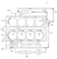
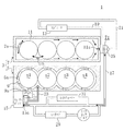
図1は、本実施形態に係るエンジンの冷却装置1の構成を模式的に示す。この冷却装置1は、エンジンの本体部3を構成するシリンダブロック5及びシリンダヘッド7にそれぞれ形成された冷却水通路としてのウォータジャケット9,11と、外気によって冷却水を冷やすために車両の前部等に配設されたラジエータ13と、冷却水を循環させるウォータポンプ15と、冷却水の温度が高くなると開弁して冷却水の循環系統を切り換える第1及び第2サーモスタット弁25,27とを備えている。本発明で言うところの主冷却水回路85とは、シリンダブロック5のウォータジャケット9、シリンダヘッド7のウォータジャケット11、ラジエータ13及びウォータポンプ15を冷却水の循環方向においてこの順に介設したものである。
(Embodiment 1)
-Overall configuration of cooling device-
FIG. 1 schematically shows a configuration of an
上記シリンダブロック5のウォータジャケット9は、4つのシリンダs1〜s4の外周を囲むようにシリンダブロック5の気筒列方向のほぼ全体に亘って形成されている。
The
また、シリンダブロック5のウォータジャケット9は、このシリンダブロック5のトップデッキに形成された連通孔部5aと、シリンダヘッド7のボトムデッキに形成された連通孔部7aとを介して、シリンダヘッド7のウォータジャケット11に連通している。このため、シリンダブロック5のウォータジャケット9を流れる冷却水は、順次シリンダヘッド7のウォータジャケット11に流通するようになっている。
The
上記シリンダヘッド7のウォータジャケット11は、各シリンダs1〜s4の吸排気ポートやプラグホール(図示せず)の外周を包み込むようにしてシリンダヘッド7の気筒列方向のほぼ全体に亘って形成されている。
The
シリンダヘッド7のウォータジャケット11の流出口11aと、ウォータポンプ15の吸入口15aとは、上記第1サーモスタット弁25を介して、2系統のルートで接続されている。第1のルートは、シリンダヘッド7のウォータジャケット11の流出口11aと上記ラジエータ13とを接続する第1冷却水通路19、ラジエータ13と第1サーモスタット弁25とを接続する第2冷却水通路21、及び第1サーモスタット弁25と上記ウォータポンプ15の吸入口15aとを接続する第3冷却水通路17を順に通るものである。
The
また、第2のルートは、第1サーモスタット弁25の閉弁時に第1サーモスタット弁25内に形成され、ラジエータ13を迂回する第1バイパス通路(弁通路)71(図5参照)、及び第3冷却水通路17を通るものである。なお、第3冷却水通路17には、冷却水を導入して空調風との間で熱交換して暖房風とする暖房用熱交換器としてのヒータコア29と、冷却水と変速機(図示せず)の潤滑油との間で熱交換するオイルウォーマ31とが備えられている。
Further, the second route is formed in the
上記ウォータポンプ15の吐出口15bは、上記第2サーモスタット弁27を介して、シリンダブロック5のウォータジャケット9の流入口9aと接続されている。さらに、ウォータポンプ15の吐出口15bは、第2バイパス通路23によりシリンダヘッド7のウォータジャケット11の流入口11bとも接続されている。この第2バイパス通路23は、ウォータポンプ15下流側の第2サーモスタット弁27を介して分岐し、且つシリンダブロック5のウォータジャケット9を迂回してシリンダヘッド7のウォータジャケット11と連通している。
The discharge port 15 b of the
以上のように構成されたエンジンの冷却装置1における冷却水の全体的な流れは、主冷却水回路85のウォータポンプ15上流側に設けられた第1サーモスタット弁25及びウォータポンプ15下流側に設けられた第2サーモスタット弁27の開閉に応じて、図2〜図4に模式的に示すように変化する。
The overall flow of the cooling water in the
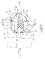
図2は、第1サーモスタット弁(メインサーモスタット弁)25及び第2サーモスタット弁(サブサーモスタット弁)27がともに開いているときの冷却水の流れを示している。ウォータポンプ15から吐出された冷却水は、第2サーモスタット弁27を通り、シリンダブロック5のウォータジャケット9に送られる。そして、冷却水はシリンダブロック5のウォータジャケット9内を流れるとともにシリンダヘッド7のウォータジャケット11にも流れ、第1冷却水通路19を通ってラジエータ13に至る。ラジエータ13で冷却された冷却水は、第2冷却水通路21、第1サーモスタット弁25、及び第3冷却水通路17を順に通ってウォータポンプ15に戻る。つまり、第1及び第2サーモスタット弁25,27がともに開いているときは、冷却水は主冷却水回路85を循環する。
FIG. 2 shows the flow of cooling water when both the first thermostat valve (main thermostat valve) 25 and the second thermostat valve (sub thermostat valve) 27 are open. The cooling water discharged from the
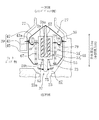
図3は、第1及び第2サーモスタット弁25,27がともに閉じているときの冷却水の流れを示している。ウォータポンプ15から吐出された冷却水は、第2サーモスタット弁27及び第2バイパス通路23を順に通って、シリンダヘッド7のウォータジャケット11に送られる。そして、シリンダヘッド7のウォータジャケット11から流出した冷却水は、第1バイパス通路71及び第3冷却水通路17を順に通ってウォータポンプ15に戻る。
FIG. 3 shows the flow of cooling water when both the first and
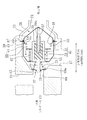
図4は、第1サーモスタット弁25が閉じていて、第2サーモスタット弁27が開いているときの冷却水の流れを示している。ウォータポンプ15から吐出された冷却水は、第2サーモスタット弁27を通り、シリンダブロック5のウォータジャケット9に送られる。そして、冷却水はシリンダブロック5のウォータジャケット9内を流れるとともにシリンダヘッド7のウォータジャケット11にも流れる。シリンダヘッド7のウォータジャケット11から流出した冷却水は、第1バイパス通路71及び第3冷却水通路17を順に通ってウォータポンプ15に戻る。
FIG. 4 shows the flow of cooling water when the
−サーモスタット弁の構成−
以下、上記第1及び第2サーモスタット弁25,27の構成を詳細に説明する。
-Configuration of thermostat valve-
Hereinafter, the configuration of the first and
<第1サーモスタット弁>
第1サーモスタット弁25は、冷却水の温度に応じて開閉するワックス・ペレット型サーモスタット弁であり、図5はその閉弁時の状態を、また図6はその開弁時の状態をそれぞれ示している。第1サーモスタット弁25は、第2冷却水通路21の一部を構成するパイプ状のハウジング33内に取り付けられていて、第1サーモスタット弁25の開弁時に冷却水を弁通路65を介して第3冷却水通路17(主冷却水回路85側)に流通させる主弁部35と、第1サーモスタット弁25の閉弁時に冷却水を第1バイパス通路71を介して第3冷却水通路17に流通させるバイパス弁部37とを有しており、該第1サーモスタット弁25をハウジング33に固定するサーモスタット基体部39と、このサーモスタット基体部39に対し後述する弁体変位方向に相対変位するサーモスタット本体部41とを備えている。
<First thermostat valve>
The
上記サーモスタット基体部39は、ハウジング33に取り付けられるとともに主弁部35の一部をなす弁座43と、この弁座43よりもシリンダヘッド7側(弁体変位方向一方側)に設けられたスプリング支持部45と、弁座43に対しスプリング支持部45とは反対側(弁体変位方向他方側)に設けられた軸支持部47とを備えている。
The
上記弁座43は、円環状の支持板43aと円環状の弁座板43cと略筒状の立壁部43bとを有している。
The
上記支持板43aは、その外周縁部がハウジング33に埋め込まれることにより、該ハウジング33に固定されている。上記弁座板43cは、その外径が支持板43aの内径よりも小さく、支持板43aと平行に且つ支持板43aよりも弁体変位方向一方側に配置さている。この弁座板43cの内周縁が冷却水を主冷却水回路85側に流通させるための流通孔49を区画している。上記立壁部43bは、支持板43aの内周縁と弁座板43cの外周縁とを全周に亘って連結している。換言すれば、弁座43は、弁体変位方向他方側端部に外側に延出するフランジ(支持板43a)を有するとともに弁体変位方向一方側端部に内側に延出するフランジ(弁座板43c)を有する略円錐筒状をなしている。
The
上記スプリング支持部45及び上記軸支持部47は支持板43aを介してハウジング33に取り付けられている。これらの支持部45,47はともに骨組構造体であり、冷却水の流通を遮らない構造となっている。
The
一方、上記サーモスタット本体部41は、ピストンロッド51と感温ケース53とを備えている。
On the other hand, the thermostat
上記ピストンロッド51は、弁体変位方向に延びており、その弁体変位方向他方側端部が軸支持部47に固定されていて、弁座板43cに対し垂直にかつ流通孔49を貫通するように配置されている。また、ピストンロッド51の弁体変位方向一方側端部には有底筒状のシール部材57が装着されている。
The
上記感温ケース53は有底有蓋円筒状の胴部59を有し、その底部(弁体変位方向他方側端部)には貫通孔59aが形成されるとともに、蓋部(弁体変位方向一方側)には円筒軸方向に延びるロッド部59bが突設されている。この貫通孔59aにはシール部材57で覆われたピストンロッド51が挿入されており、これにより、感温ケース53がピストンロッド51に沿ってロッド軸方向(弁体変位方向)に移動可能となっている。シール部材57と感温ケース53の間には、熱膨張体であるワックス55が充填されている。
The temperature-
さらに、感温ケース53は、その胴部59に略円環板状の主弁体61を備えるとともに、そのロッド部59bに略円環板状のバイパス弁体63を備えている。
Furthermore, the temperature-
上記主弁体61は、その内周縁部が胴部59に固定されるとともに、上記弁座板43cと略同じ外径を有している。主弁体61は、上記弁座43とともに上記主弁部35を構成しており、感温ケース53の移動に伴って弁開閉方向(弁体変位方向)に変位する。主弁体61の弁体変位方向一方側面には、上記スプリング支持部45に支持された主スプリング67が取り付けられている。これにより、感温ケース53は主スプリング67によって常時弁体変位方向他方側に付勢されている。
The
上記バイパス弁体63はロッド部59bに移動可能に取り付けられるとともに、シリンダヘッド7側のパイプ状のハウジング69の内径よりも大きな外径を有しており、シリンダヘッド7側のハウジング69の段差部69aとともにバイパス弁部37を構成する。バイパス弁体63は、胴部59の蓋部とバイパススプリング73で接続されており、このバイパススプリング73により常時弁体変位方向一方側に付勢される一方、ロッド部59bに固定されたストッパーリング75によりロッド部59bから抜けないようになっている。
The
上記ワックス55は、感温ケース53を介して伝わる冷却水の温度が高くなったときには膨張し、冷却水の温度が低くなったときには収縮する。ワックス55の充填量は、冷却水の温度が第2所定温度T2以上のときは主弁体61がワックス55の膨張力により主スプリング67の付勢力に抗して弁座板43cから離れるように弁体変位方向一方側に変位し、かつ、冷却水の温度が第2所定温度T2未満のときは主弁体61が主スプリング67の付勢力により弁座板43cに当接するような値に設定されている。
The
以上のように構成された第1サーモスタット弁25は、冷却水の温度が第2所定温度T2未満のときは、図5に示すように、主スプリング67の付勢力により主弁部35が閉弁するとともにバイパス弁部37が開弁して、冷却水を第1バイパス通路71に流通させる。より具体的には、以下の通りである。
When the temperature of the cooling water is lower than the second predetermined temperature T2, the
冷却水の温度が第2所定温度T2未満のときはワックスが膨張しないので感温ケース53は移動しない。このため、主弁体61が主スプリング67の付勢力によって弁座板43cに当接して流通孔49を塞ぐことにより、主弁部35が閉弁する。このとき、バイパス弁体63はハウジング69の段差部69aから離れるように弁体変位方向他方側に変位しており、ハウジング69の段差部69aとの間の弁通路71が開くことにより、バイパス弁部37が開弁する。これらにより、第1サーモスタット弁25が閉弁し、冷却水が第1バイパス通路71を通って第3冷却水通路17側に流通する。
When the temperature of the cooling water is lower than the second predetermined temperature T2, the temperature-
一方、第1サーモスタット弁25は、冷却水の温度が第2所定温度T2以上のときは、図6に示すように、ワックス55の膨張力により主弁部35が開弁するとともにバイパス弁部37が閉弁して、冷却水を第1冷却水通路19側に流通させる。より具体的には、以下の通りである。
On the other hand, when the temperature of the cooling water is equal to or higher than the second predetermined temperature T2, the
冷却水の温度が第2所定温度T2以上のときはワックスが膨張するので、主スプリング67の付勢力に抗して感温ケース53が弁体変位方向一方側に移動する。このため、主弁体61がワックス55の膨張力によって弁座板43cから離れるように弁体変位方向一方側に変位して弁座板43cとの間の弁通路65を開き流通孔49に冷却水が流通される状態となり、主弁部35が開弁する。このとき、バイパス弁体63がハウジング69の段差部69aに当接することにより、バイパス弁部37が閉弁する。これらにより、第1サーモスタット弁25が開弁し、冷却水が第1冷却水通路19及び第2冷却水通路21を通って第3冷却水通路17(主冷却水回路側85)に流通する。
Since the wax expands when the temperature of the cooling water is equal to or higher than the second predetermined temperature T2, the
ここで、主弁部35の弁通路65は、弁座板43cの流通孔49に冷却水を流通させるために、主弁体61が弁体変位方向一方側に移動することにより弁座板43cと主弁体61との間に形成される通路であり、その通路面積は、弁体変位方向(弁開閉方向)における弁座板43cと主弁体61との間隔、すなわち、弁座板43cに対する主弁体61の変位量に比例して大きくなる。
Here, the
<第2サーモスタット弁>
第2サーモスタット弁27は、主弁体79の形状が第1サーモスタット弁25と異なるものである。以下、第1サーモスタット弁25と異なる点について説明する。
<Second thermostat valve>
The
第2サーモスタット弁27は、冷却水の温度に応じて開閉するワックス・ペレット型サーモスタット弁であり、図7はその閉弁時の状態を、また図8はその開弁時の状態をそれぞれ示している。第2サーモスタット弁27は、ウォータポンプ15とシリンダブロック5のウォータジャケット9との接続部を構成するパイプ状のハウジング77内に取り付けられており、第2サーモスタット弁27の開弁時に冷却水を弁通路81を介してシリンダブロック5のウォータジャケット9側(主冷却水回路側)に流通させる主弁部35と、第2サーモスタット弁27の閉弁時に冷却水を弁通路87を介して第2バイパス通路23側に流通させるバイパス弁部37とを有している。また、第2サーモスタット弁27のワックス55は、冷却水の温度が上記第2所定温度T2よりも極めて低い第3所定温度T3以上のときに膨張するように設定されている。
The
第2サーモスタット弁27は、感温ケース53の胴部59に略円錐筒状の主弁体79を備えている。主弁体79は、弁座43とともに主弁部35を構成するものであり、略円環状の頂壁部79aと円環状の底壁部79cと略筒状の立壁部79bとを有している。
The
上記頂壁部79aは、その内周縁部が胴部59に固定され且つ弁座板43cの内径よりも小さい外形を有している。上記底壁部79cは、弁座板43cと同形同大であり、頂壁部79aと平行に且つ頂壁部よりも弁体変位方向他方側(シリンダブロック5側と反対側)に配置されている。上記立壁部79bは、頂壁部79aの外周縁と底壁部79cの内周縁とを全周に亘って連結している。
The
立壁部79bは、弁体変位方向の底壁部79c側から頂壁部79a側に向かうほど、すなわち、底壁部79cの内周縁部から離れるに従って筒径方向内側に傾斜しており、流通孔49に対し弁体変位方向(弁開閉方向)に抜き差し可能になっている。立壁部79bの弁体変位方向長さは、冷却水の温度が第2所定温度T2よりも低く第3所定温度T3よりも高い第1所定温度T1になったときに、立壁部79bが流通孔49から抜けるような長さに設定されている。また、立壁部79bの傾斜角は、弁体変位方向に対し45度以下の緩い傾斜角となっている。
The standing
頂壁部79aの弁体変位方向他方側面にはスプリング支持部45に支持された主スプリング67が取り付けられており、これにより、感温ケース53は常時弁体変位方向一方側(シリンダブロック5側)に付勢されている。
A
以上のように構成された第2サーモスタット弁27は、冷却水の温度が第3所定温度T3未満のときは、図7に示すように、主スプリング67の付勢力により主弁部35が閉弁するとともにバイパス弁部37が開弁して、冷却水を第2バイパス通路23側に流通させる。より具体的には、以下の通りである。
When the temperature of the cooling water is lower than the third predetermined temperature T3, the
冷却水の温度が第3所定温度T3未満のときはワックスが膨張しないので感温ケース53は移動しない。このため、底壁部79cが主スプリング67の付勢力によって弁座板43cに当接するとともに立壁部79bが流通孔49に差し込まれて流通孔49を塞ぐことにより、主弁部35が閉弁する。このとき、バイパス弁体63は第2バイパス通路23の段差部23aから離れるように弁体変位方向一方側に変位しており、該段差部23aとの間の弁通路87が開くことにより、バイパス弁部37が開弁する。これらにより、第2サーモスタット弁27が閉弁し、冷却水が第2バイパス通路23側に流通する。
When the temperature of the cooling water is lower than the third predetermined temperature T3, the wax does not expand and the temperature
一方、冷却水の温度が第3所定温度T3以上のときは、ワックス55の膨張力により主弁部35が開弁するとともにバイパス弁部37が閉弁して、冷却水をシリンダブロック5のウォータジャケット9に流通させる。より具体的には、以下の通りである。
On the other hand, when the temperature of the cooling water is equal to or higher than the third predetermined temperature T3, the
冷却水の温度が第3所定温度T3以上のときはワックスが膨張するので、主スプリング67の付勢力に抗して感温ケース53が弁体変位方向他方側に移動する。このため、冷却水の温度が第1所定温度T1以下のときには、立壁部79bがワックス55の膨張力によって弁座板43cから抜ける(離れる)ように弁体変位方向他方側に変位して弁座板43cとの間の弁通路81を開き流通孔49に冷却水が流通される状態となり、主弁部35が開弁する。このとき、バイパス弁体63は第2バイパス通路23の段差部69a側に変位することにより、バイパス弁部37は若干閉じ加減の開弁状態となる。これらにより、第2サーモスタット弁27が開弁し、冷却水がシリンダブロック5のウォータジャケット9側に流通する。
Since the wax expands when the temperature of the cooling water is equal to or higher than the third predetermined temperature T3, the
ここで、主弁部35の弁通路81は、弁座板43cの流通孔49に冷却水を流通させるために、主弁体79が弁体変位方向他方側に移動することにより弁座板43cと立壁部79bとの間に形成される通路であり、その通路面積は、弁座板43cに対する主弁体79の変位量に比例して大きくなるのではなく、弁座板43cの径方向における、弁座板43cと立壁部79bとの間隔に比例して大きくなる。さらに、立壁部79bの傾斜角が主弁体79の変位方向に対し45度以下であることから、弁座板43cの径方向における、弁座板43cと立壁部79bとの間隔は、弁体変位方向における弁座板43cに対する主弁体79の変位量よりも小さくなる。そして、冷却水の温度が第1所定温度T1になると、立壁部79bが流通孔49から抜けることから、主弁部35の弁通路面積は、第1サーモスタット弁25と同様に、弁座板43cに対する主弁体79の変位量に比例して大きくなる。すなわち、冷却水の温度変化に伴う第2サーモスタット弁27の開弁時の弁通路81の面積変化率は、冷却水の温度が第1所定温度T1未満のときは、冷却水の温度が第1所定温度T1以上のときよりも小さく設定されている。したがって、第2サーモスタット弁27の開弁時の冷却水流量変化率は、冷却水の温度が第1所定温度T1未満のときは、冷却水の温度が第1所定温度T1以上のときよりも小さくなる。
Here, the
−サーモスタット弁の特性−
以下、上記第1及び第2サーモスタット弁25,27の特性について詳細に説明する。
-Characteristics of thermostat valve-
Hereinafter, the characteristics of the first and
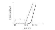
図9は、冷却水の温度に対する第1及び第2サーモスタット弁25,27の弁通路面積の変化を示す図であり、図中の実線は第1サーモスタット弁25の特性を、図中の点線は第2サーモスタット弁27の特性をそれぞれ示している。
FIG. 9 is a diagram showing changes in the valve passage areas of the first and
図9に示すように、第1サーモスタット弁25の開弁開始温度(第2所定温度T2)は第2サーモスタット弁27の開弁開始温度(第3所定温度T3)よりも高く設定されているとともに、第1サーモスタット弁25の全開(最大開弁)温度(第4所定温度T4)は第2サーモスタット弁27の全開温度(第5所定温度T5)よりも高く設定されている。
As shown in FIG. 9, the valve opening start temperature (second predetermined temperature T2) of the
第1サーモスタット弁25の開弁開始温度を第2サーモスタット弁27の開弁開始温度よりも高く設定するのは、低負荷運転時に冷却水がシリンダブロック5のウォータジャケット9に流れなくなるのを回避するためである。仮に第1サーモスタット弁25が第2サーモスタット弁27よりも先に開弁すると、第2サーモスタット弁27にはラジエータ13により冷却された冷却水が流れることから、第2サーモスタット弁27が開かなくなり、シリンダブロック5におけるオイル消費の増加や、シリンダライナ(図示せず)の焼き付きが発生するほどにシリンダブロック5が高温になる。そこで、本実施形態では、第2サーモスタット弁27を第1サーモスタット弁25よりも先に開弁させて、シリンダブロック5が高温になるのを防いでいる。
Setting the valve opening start temperature of the
一方、第1サーモスタット弁25の全開温度を第2サーモスタット弁27の全開温度よりも高く設定するのは、第1サーモスタット弁25よりも先に第2サーモスタット弁27を全開させて、高負荷運転時にシリンダブロック5のウォータジャケット9に流れる冷却水の流量を十分に確保するためである。つまり、シリンダブロック5における燃費効果が問題とならない高負荷運転時には、ラジエータ13で冷却された冷却水をシリンダブロック5及びシリンダヘッド7のウォータジャケット9,11に行き渡らせて、エンジンの本体部3全体の冷却効果を優先させている。
On the other hand, the reason why the fully open temperature of the
ここで、第4所定温度T4は第5所定温度T5よりも4℃以上高く設定することが望ましい。その理由は、以下の通りである。 Here, it is desirable that the fourth predetermined temperature T4 is set to be 4 ° C. higher than the fifth predetermined temperature T5. The reason is as follows.
サーモスタット弁25,27に内蔵されるワックス55は不純物を含有させることにより、開弁開始温度や全開温度を調整することができるが、設定温度に対しプラスマイナス2℃程度の誤差が不可避的に生じる場合がある。このため、例えば、第4所定温度T4と第5所定温度T5との差を3℃に設定した場合に、第1サーモスタット弁25がマイナス2℃の誤差を有し、第2サーモスタット弁27がプラス2℃の誤差を有していると、第2サーモスタット弁27の全開温度が第1サーモスタット弁25の全開温度よりも高くなり、高負荷運転時における第2サーモスタット弁27の最大開弁量を確保できないおそれがある。したがって、第4所定温度T4と第5所定温度T5の差を4℃以上とすることにより、第1サーモスタット弁25がマイナス2℃の誤差を有し、第2サーモスタット弁27がプラス2℃の誤差を有しているときでも、第2サーモスタット弁27の最大開弁量を確保できるようにしている。
The
また、第2サーモスタット弁27の開弁時の冷却水流量変化率は、冷却水の温度が第1所定温度T1未満のときは、冷却水の温度が第1所定温度T1以上のときよりも小さく設定されている。その理由は、以下の通りである。
The rate of change in the coolant flow rate when the
本実施形態の冷却装置1では、冷却水の温度が第1所定温度T1よりもさらに低い第3所定温度T3のときに第2サーモスタット弁27の開弁を開始させている。このように第2サーモスタット弁27を早期に開弁させることにより、ワックス55が冷却水の昇温に対し即座に応答して膨張できる待ち受け温度領域(図9中のX)を設けることができる。したがって、ワックス55自体が暖まるまでは開弁を開始しないという従来のワックス・ペレット型サーモスタット弁の欠点を補うことができる。つまり、シリンダブロック5が高温になったときに、直ぐにそのウォータジャケット9に冷却水を必要量だけ流せるように、冷却水が低温の段階から第2サーモスタット弁27を開弁させておくのである。
In the
しかしながら、シリンダブロック5が高温になっていない状態で、シリンダブロック5のウォータジャケット9に冷却水を流通させると、シリンダブロック5の昇温が促進されない。そこで、冷却水の温度が第1所定温度T1未満のときは第2サーモスタット弁27の開弁時の冷却水流量変化率を小さくして、冷間始動時におけるシリンダブロック5のウォータジャケット9への冷却水の流通量を少なくしたのである。
However, if the coolant is circulated through the
なお、第2サーモスタット弁27はシリンダブロック5のウォータジャケット9への冷却水の流通を制御する弁であるから、電磁式サーモスタット弁のようにシリンダブロック5のシリンダライナ温度を直接検出し、それに応じて制御することが望ましいが、本発明では冷却水の温度により第2サーモスタット弁27の開閉を制御している。その理由は、以下の通りである。
Since the
第2サーモスタット弁27が閉じている状態、又はシリンダブロック5のウォータジャケット9を流れる冷却水が少ない状態では、冷却水の温度はほぼシリンダヘッド7の温度に依存する。また、シリンダヘッド7の温度とシリンダライナ温度には相関性がある。したがって、冷却水の温度とシリンダライナ温度にも相関性があるので、冷却水の温度により第2サーモスタット弁27の開閉を制御しても、シリンダライナ温度を管理できるからである。
When the
−冷却装置の作用−
以下、上記のように構成されたエンジンの冷却装置1の動作を説明する。
-Action of cooling device-
The operation of the
冷却水の温度が低いエンジンの冷間始動時には、図5及び図7に示すように、第1及び第2サーモスタット弁25,27が主スプリング67の付勢力により閉じている。ウォータポンプ15から吐出された冷却水は、図3に示すように、シリンダブロック5のウォータジャケット9を迂回して、第2サーモスタット弁27及び第2バイパス通路23を順に通って、シリンダヘッド7のウォータジャケット11に送られる。シリンダヘッド7のウォータジャケット11から流出した冷却水は、第1バイパス通路71及び第3冷却水通路17を順に通ってウォータポンプ15に戻る。
When the engine having a low cooling water temperature is cold-started, the first and
シリンダヘッド7との熱交換により冷却水の温度が第3所定温度T3まで上昇すると、第2サーモスタット弁27が開弁を開始する。第2サーモスタット弁27に内蔵されたワックス55の膨張力により主弁体79が弁座43から離れるように変位すると、立壁部79bと弁座板43cとの間の弁通路81が開き徐々にその通路面積が大きくなっていく。このとき、ウォータポンプ15から吐出された冷却水は、図10に示すように、そのほとんどが第2バイパス通路23を通ってシリンダヘッド7のウォータジャケット11に送られるが(図10の太線矢印)、シリンダブロック5のウォータジャケット9にも少量の冷却水が送られる(図10の細線矢印)。
When the temperature of the cooling water rises to the third predetermined temperature T3 due to heat exchange with the cylinder head 7, the
冷却水の温度がさらに上昇し第1所定温度T1に達すると、第2サーモスタット弁27のワックス55の膨張力により主弁体79が弁座43から離れるように変位して、立壁部79bが弁座板43cから抜けて弁通路面積が急激に大きくなる。このとき、ウォータポンプ15から吐出された冷却水は、図4に示すように、シリンダブロック5のウォータジャケット9に送られ、連通孔部5a,7aを通ってシリンダヘッド7のウォータジャケット11に送られる。そして、シリンダヘッド7のウォータジャケット11を流れた冷却水は、ラジエータ13を迂回して第1バイパス通路71及び第1冷却水通路17を流通しウォータポンプ15に戻る。
When the temperature of the cooling water further rises and reaches the first predetermined temperature T1, the
冷却水の温度がさらに上昇し第2所定温度T2になると、図6に示すように、第1サーモスタット弁25がワックス55の膨張力により開弁する。このとき、ウォータポンプ15から吐出され、シリンダブロック5のウォータジャケット9及びシリンダヘッド7のウォータジャケット11を流れた冷却水は、図2に示すように、第1冷却水通路19を通ってラジエータ13に至る。
When the temperature of the cooling water further rises to the second predetermined temperature T2, the
−効果−
本実施形態では、第2サーモスタット弁27は冷却水の温度が低いときに開弁し、かつ、冷却水の温度が第1所定温度T1未満のときは、冷却水の温度が該第1所定温度T1以上のときよりも開弁時の冷却水流量変化率が小さく設定されている。このように第2サーモスタット弁27を冷却水の温度が低いときから開弁させることにより、冷却水が昇温するとワックス55が直ぐに膨張を開始する待ち受け温度領域Xを設けることができる。これにより、冷却水の温度変化に対する第2サーモスタット弁27の応答性が高まるので、冷却水の温度が急激に上昇しても、シリンダブロック5のウォータジャケット9に冷却水を直ちに流通させることができる。したがって、エンジン始動直後の高負荷運転時にシリンダライナの温度応答遅れによる信頼性の低下を抑制できる。
-Effect-
In the present embodiment, the
また、第1所定温度T1未満のときはシリンダブロック5のウォータジャケット9への冷却水の流通量を少なくするので、冷間始動時にシリンダブロック5を高温に保持することができるとともに、シリンダヘッド7と冷却水との熱交換が積極的に行われるので冷却水を早期に昇温させることができる。したがって、冷却装置1の構造を複雑にすることなく、冷間始動時における燃費の低減を図ることができる。
Further, when the temperature is lower than the first predetermined temperature T1, the circulation amount of the cooling water to the
さらに、冷却水の温度が第1所定温度T1未満のときは、第2サーモスタット弁27の主弁部35の弁通路81の面積変化率を小さくすることによって、シリンダブロック5のウォータジャケット9への冷却水の流通量を少なくできる。したがって、冷却装置1の構造を複雑にすることなく、冷間始動時における燃費の低減を図ることができる。
Furthermore, when the temperature of the cooling water is lower than the first predetermined temperature T1, the area change rate of the
また、第2サーモスタット弁27の主弁体79に内側に傾斜した略筒状の弁体壁部79bを備えるだけの簡単な構造で、冷却水の温度が第1所定温度未満のときは、冷却水の温度変化に伴って主弁体79を変位させながら、弁通路面積変化率だけを小さくすることができる。
Moreover, when the temperature of the cooling water is lower than the first predetermined temperature, the
(実施形態2)
本実施形態は、第2サーモスタット弁27の弁座43の構造が実施形態1と異なるものである。以下、実施形態1と異なる点について説明する。
(Embodiment 2)
In the present embodiment, the structure of the
−サーモスタット弁の構成−
図11に示すように、第2サーモスタット弁27の弁座板43cには、制限壁部83が形成されている。この制限壁部83は、弁座板43cの外周縁部から弁体変位方向他方側に延びる筒状体であり、底壁部79cと弁座板43cとの間に形成される弁通路81の面積変化を規制するために、底壁部79cを囲んでいる。制限壁部83の弁体変位方向長さは、開弁開始時に弁座板43cに当接している底壁部79cが、ワックス55の膨張力により弁体変位方向他方側に変位して、冷却水の温度が第1所定温度T1になったときに該制限壁部83から抜けるような長さに設定されている。
-Configuration of thermostat valve-
As shown in FIG. 11, a
以上のように構成された第2サーモスタット弁27は、冷却水の温度が第3所定温度T3以上のときは、冷却水をシリンダブロック5のウォータジャケット9側に流通させるが、冷却水の温度が第1所定温度T1になるまでは、制限壁部83が弁通路81の面積変化を規制しているので、第2サーモスタット弁27の開弁時の弁通路81の面積は、冷却水の温度が第1所定温度T1未満のときは、一定になるように設定されている。
The
−サーモスタット弁の特性−
以下、上記第2サーモスタット弁27の特性に関し、実施形態1と異なる点について説明する。
-Characteristics of thermostat valve-
Hereinafter, regarding the characteristics of the
図12は、冷却水の温度に対する第1及び第2サーモスタット弁25,27の弁通路面積の変化を示す図であり、図中の実線は第1サーモスタット弁25の特性を、図中の点線は第2サーモスタット弁27の特性をそれぞれ示している。
FIG. 12 is a diagram showing changes in the valve passage areas of the first and
第2サーモスタット弁27では、開弁時の弁通路81の面積が冷却水の温度が第1所定温度T1未満のときは一定になるように、すなわち、第2サーモスタット弁27の開弁時の冷却水流量は、冷却水の温度が第1所定温度T1未満のときは、一定になるように設定されている。
In the
このように冷却水の温度が第1所定温度T1未満のときに第2サーモスタット弁27の開弁時の冷却水流量を一定にするのは、冷間始動時におけるシリンダブロック5のウォータジャケット9への冷却水の流通量をより一層少なくするためである。
As described above, when the temperature of the cooling water is lower than the first predetermined temperature T1, the flow rate of the cooling water when the
−効果−
本実施形態によれば、第1所定温度T1未満のときはシリンダブロック5のウォータジャケット9への冷却水の流通量がより少なくなるので、シリンダブロック5をより高温に保持することができる。したがって、冷間始動時における燃費の低減をより一層図ることができる。
-Effect-
According to this embodiment, when the temperature is lower than the first predetermined temperature T1, the circulation amount of the cooling water to the
また、冷却水の温度が上記第1所定温度T1未満のときは、第2サーモスタット弁27の主弁部35の弁通路81の面積を一定にすることによって、シリンダブロック5のウォータジャケット9への冷却水の流通量をより少なくできる。したがって、冷却装置1の構造を複雑にすることなく、冷間始動時における燃費の低減をより一層図ることができる。
Further, when the temperature of the cooling water is lower than the first predetermined temperature T1, the area of the
さらに、第2サーモスタット弁27の弁座43に筒状の制限壁部83を備えるだけの簡単な構造で、冷却水の温度が第1所定温度T1未満のときは、冷却水の温度変化に伴って主弁体79を変位させながら、弁通路81の面積変化だけを規制することができる。
Furthermore, when the temperature of the cooling water is less than the first predetermined temperature T1 with a simple structure in which the
本発明は、実施形態に限定されず、その精神又は主要な特徴から逸脱することなく他の色々な形で実施することができる。 The present invention is not limited to the embodiments, and can be implemented in various other forms without departing from the spirit or main features thereof.
このように、上述の実施形態はあらゆる点で単なる例示に過ぎず、限定的に解釈してはならない。さらに、特許請求の範囲の均等範囲に属する変形や変更は、全て本発明の範囲内のものである。 As described above, the above-described embodiment is merely an example in all respects and should not be interpreted in a limited manner. Further, all modifications and changes belonging to the equivalent scope of the claims are within the scope of the present invention.
以上説明したように、本発明は、サーモスタット弁を備えたエンジンの冷却装置等について有用である。 As described above, the present invention is useful for an engine cooling device provided with a thermostat valve.
1 エンジンの冷却装置
5 シリンダブロック
7 シリンダヘッド
9 シリンダブロックのウォータジャケット
11 シリンダヘッドのウォータジャケット
13 ラジエータ
15 ウォータポンプ
23 第2バイパス通路
25 第1サーモスタット弁
27 第2サーモスタット弁
43 弁座
43c 弁座板
49 流通孔
71 弁通路(第1バイパス通路)
79 主弁体(弁体)
79b 立壁部
79c 底壁部
81 弁通路
83 制限壁部
85 主冷却水回路
T1 第1所定温度
T2 第2所定温度(第1サーモスタット弁の開弁開始温度)
T3 第3所定温度(第2サーモスタット弁の開弁開始温度)
T4 第4所定温度(第1サーモスタット弁の全開温度)
T5 第5所定温度(第1サーモスタット弁の全開温度)
DESCRIPTION OF
79 Main valve (valve)
79b
T3 third predetermined temperature (opening start temperature of the second thermostat valve)
T4 4th predetermined temperature (full open temperature of the 1st thermostat valve)
T5 5th predetermined temperature (full open temperature of the 1st thermostat valve)
Claims (6)
上記主冷却水回路の上記ウォータポンプ上流側に設けられ、冷却水の温度に応じて開閉し、開弁時には冷却水を上記主冷却水回路側に流通させる一方、閉弁時には冷却水を上記第1バイパス通路側に流通させる第1サーモスタット弁と、
上記主冷却水回路の上記ウォータポンプ下流側に設けられ、冷却水の温度に応じて開閉し、開弁時には冷却水を上記主冷却水回路側に流通させる一方、閉弁時には冷却水を上記第2バイパス通路側に流通させる第2サーモスタット弁とをさらに備え、
上記第1サーモスタット弁の開弁開始温度が上記第2サーモスタット弁の開弁開始温度よりも高く設定されているとともに、上記第1サーモスタット弁の全開温度が上記第2サーモスタット弁の全開温度よりも高く設定され、
冷却水の温度変化に伴う上記第2サーモスタット弁の開弁時の冷却水流量変化率が、冷却水の温度が上記第1サーモスタット弁の開弁開始温度よりも低い第1所定温度未満のときは、該第1所定温度以上のときよりも小さく設定されていることを特徴とするエンジンの冷却装置。 A water jacket for the cylinder block, a water jacket for the cylinder head, a radiator, and a water pump are provided in this order in the circulation direction of the cooling water, and the first cooling water circuit bypasses the radiator. A bypass passage and a second bypass passage which branches from the water pump downstream side of the main cooling water circuit, bypasses the water jacket of the cylinder block and communicates with the water jacket of the cylinder head, and cools during cold start An engine cooling apparatus for circulating water through the first and second bypass passages,
Provided on the upstream side of the water pump of the main cooling water circuit, and opens and closes according to the temperature of the cooling water. When the valve is opened, the cooling water is circulated to the main cooling water circuit side. A first thermostat valve that circulates to the bypass passage side;
Provided on the downstream side of the water pump of the main cooling water circuit, and opens and closes according to the temperature of the cooling water. When the valve is opened, the cooling water flows to the main cooling water circuit side. 2 further comprising a second thermostat valve that circulates to the bypass passage side,
The valve opening start temperature of the first thermostat valve is set higher than the valve opening start temperature of the second thermostat valve, and the fully open temperature of the first thermostat valve is higher than the fully open temperature of the second thermostat valve. Set,
When the cooling water flow rate change rate at the time of opening of the second thermostat valve due to the temperature change of the cooling water is lower than the first predetermined temperature lower than the valve opening start temperature of the first thermostat valve The engine cooling apparatus is set smaller than the first predetermined temperature or more.
上記第2サーモスタット弁は、冷却水を上記主冷却水回路側に流通させるための流通孔が形成された弁座と、弁体とを有し、
上記弁座と上記弁体との間には、上記流通孔に冷却水を流通させるための弁通路が形成され、
上記弁体は、上記第2サーモスタット弁の開弁時に、上記弁座から離れるように変位して上記弁通路を開くことにより冷却水を上記主冷却水回路側に流通させる一方、上記第2サーモスタット弁の閉弁時に、上記弁座に当接して上記流通孔を塞ぐことにより冷却水を上記第2バイパス通路側に流通させ、
冷却水の温度変化に伴う上記第2サーモスタット弁の開弁時の上記弁通路の面積変化率が、冷却水の温度が上記第1所定温度未満のときは、冷却水の温度が該第1所定温度以上のときよりも小さく設定されていることを特徴とするエンジンの冷却装置。 The engine cooling device according to claim 1,
The second thermostat valve has a valve seat in which a flow hole for flowing cooling water to the main cooling water circuit side is formed, and a valve body,
Between the valve seat and the valve body, a valve passage for circulating cooling water through the flow hole is formed,
When the second thermostat valve is opened, the valve body displaces away from the valve seat and opens the valve passage to circulate cooling water to the main cooling water circuit side, while the second thermostat When the valve is closed, the cooling water is made to flow to the second bypass passage side by closing the flow hole by contacting the valve seat,
When the rate of change of the area of the valve passage when the second thermostat valve is opened due to the temperature change of the cooling water is less than the first predetermined temperature, the temperature of the cooling water is the first predetermined temperature. A cooling device for an engine characterized by being set smaller than when the temperature is higher than the temperature.
上記弁座は、上記流通孔が形成された円環状の弁座板を有し、
上記弁体は、上記第2サーモスタット弁の閉弁時に上記弁座板に当接する円環状の底壁部と、該底壁部の内周縁部から弁体変位方向に延びて該内周縁部から離れるに従って径方向内側に傾斜し、上記流通孔に対し弁体変位方向に抜き差し可能な略筒状の立壁部とを有し、
上記弁通路は、上記弁座板と上記立壁部との間に形成されるものであり、
上記立壁部は、上記第2サーモスタット弁の開弁時に上記弁座板から離れるように変位して上記弁通路を開き、
上記立壁部の弁体変位方向長さが、上記第1所定温度のときに該立壁部が上記流通孔から抜けるような長さに設定されていることを特徴とするエンジンの冷却装置。 The engine cooling device according to claim 2,
The valve seat has an annular valve seat plate in which the flow hole is formed,
The valve body includes an annular bottom wall portion that comes into contact with the valve seat plate when the second thermostat valve is closed, and extends from the inner peripheral edge portion of the bottom wall portion in the valve body displacement direction. Inclined radially inward as it leaves, and has a substantially cylindrical standing wall that can be inserted and removed in the valve body displacement direction with respect to the flow hole,
The valve passage is formed between the valve seat plate and the standing wall portion,
The upright wall portion is displaced away from the valve seat plate when the second thermostat valve is opened to open the valve passage,
The engine cooling device according to claim 1, wherein a length of the upright wall portion in the valve body displacement direction is set to such a length that the upright wall portion can be removed from the flow hole at the first predetermined temperature.
上記第2サーモスタット弁の開弁時の冷却水流量が、冷却水の温度が上記第1所定温度未満のときは、一定になるように設定されていることを特徴とするエンジンの冷却装置。 The engine cooling device according to claim 1,
An engine cooling apparatus, wherein the flow rate of the cooling water when the second thermostat valve is opened is set to be constant when the temperature of the cooling water is lower than the first predetermined temperature.
上記第2サーモスタット弁は、冷却水を上記主冷却水回路側に流通させるための流通孔が形成された弁座と、弁体とを有し、
上記弁座と上記弁体との間には、上記流通孔に冷却水を流通させるための弁通路が形成され、
上記弁体は、上記第2サーモスタット弁の開弁時に、上記弁座から離れるように変位して上記弁通路を開くことにより冷却水を上記主冷却水回路側に流通させる一方、上記第2サーモスタット弁の閉弁時に、上記弁座に当接して上記流通孔を塞ぐことにより冷却水を上記第2バイパス通路側に流通させ、
上記第2サーモスタット弁の開弁時の上記弁通路の面積が、冷却水の温度が上記第1所定温度未満のときは、一定になるように設定されていることを特徴とするエンジンの冷却装置。 The engine cooling device according to claim 4.
The second thermostat valve has a valve seat in which a flow hole for flowing cooling water to the main cooling water circuit side is formed, and a valve body,
Between the valve seat and the valve body, a valve passage for circulating cooling water through the flow hole is formed,
When the second thermostat valve is opened, the valve body displaces away from the valve seat and opens the valve passage to circulate cooling water to the main cooling water circuit side, while the second thermostat When the valve is closed, the coolant flows through the second bypass passage by contacting the valve seat and closing the flow hole,
The engine cooling device characterized in that the area of the valve passage when the second thermostat valve is opened is set to be constant when the temperature of the cooling water is lower than the first predetermined temperature. .
上記弁座は、上記流通孔が形成された円環状の弁座板を有し、
上記弁体は、上記第2サーモスタット弁の閉弁時に上記弁座板に当接する円環状の底壁部を備え、
上記弁通路は、上記弁座板と上記底壁部との間に形成されるものであり、
上記弁座板には、上記弁通路の面積変化を規制するために、上記底壁部を囲むように弁体変位方向に延びる筒状の制限壁部が形成され、
上記制限壁部の弁体変位方向長さが、上記第1所定温度のときに上記底壁部が該制限壁部から抜けるような長さに設定されていることを特徴とするエンジンの冷却装置。 The engine cooling device according to claim 5,
The valve seat has an annular valve seat plate in which the flow hole is formed,
The valve body includes an annular bottom wall portion that comes into contact with the valve seat plate when the second thermostat valve is closed,
The valve passage is formed between the valve seat plate and the bottom wall portion,
The valve seat plate is formed with a cylindrical limiting wall portion extending in the valve body displacement direction so as to surround the bottom wall portion in order to regulate a change in the area of the valve passage.
The engine cooling device characterized in that the valve body displacement direction length of the limiting wall portion is set to such a length that the bottom wall portion comes out of the limiting wall portion at the first predetermined temperature. .
Priority Applications (1)
| Application Number | Priority Date | Filing Date | Title |
|---|---|---|---|
| JP2007267083A JP2009097352A (en) | 2007-10-12 | 2007-10-12 | Engine cooling system |
Applications Claiming Priority (1)
| Application Number | Priority Date | Filing Date | Title |
|---|---|---|---|
| JP2007267083A JP2009097352A (en) | 2007-10-12 | 2007-10-12 | Engine cooling system |
Publications (1)
| Publication Number | Publication Date |
|---|---|
| JP2009097352A true JP2009097352A (en) | 2009-05-07 |
Family
ID=40700603
Family Applications (1)
| Application Number | Title | Priority Date | Filing Date |
|---|---|---|---|
| JP2007267083A Pending JP2009097352A (en) | 2007-10-12 | 2007-10-12 | Engine cooling system |
Country Status (1)
| Country | Link |
|---|---|
| JP (1) | JP2009097352A (en) |
Cited By (8)
| Publication number | Priority date | Publication date | Assignee | Title |
|---|---|---|---|---|
| JP2010285894A (en) * | 2009-06-09 | 2010-12-24 | Toyota Motor Corp | Cooling device of internal combustion engine |
| JP2012167613A (en) * | 2011-02-15 | 2012-09-06 | Toyota Motor Corp | Engine |
| WO2014098710A1 (en) * | 2012-12-17 | 2014-06-26 | Scania Cv Ab | Thermostat arrangement and cooling system |
| JP2014190296A (en) * | 2013-03-28 | 2014-10-06 | Daihatsu Motor Co Ltd | Internal combustion engine |
| DE102015016673A1 (en) | 2015-01-07 | 2016-07-07 | Mazda Motor Corporation | Engine cooling system |
| JP2016125451A (en) * | 2015-01-07 | 2016-07-11 | マツダ株式会社 | Cooling device for engine |
| WO2017159766A1 (en) * | 2016-03-16 | 2017-09-21 | 本田技研工業株式会社 | Internal combustion engine cooling system |
| CN108343500A (en) * | 2017-01-25 | 2018-07-31 | 海马汽车有限公司 | A kind of car engine cooling system |
Citations (6)
| Publication number | Priority date | Publication date | Assignee | Title |
|---|---|---|---|---|
| JPS4426377Y1 (en) * | 1965-12-22 | 1969-11-05 | ||
| JPS53133040U (en) * | 1977-03-29 | 1978-10-21 | ||
| JPS6015920U (en) * | 1983-07-11 | 1985-02-02 | 日産自動車株式会社 | Internal combustion engine coolant temperature control device |
| JPS61101617A (en) * | 1984-10-23 | 1986-05-20 | Nippon Thermostat Kk | Thermostat for use in cooling water |
| JPS63297724A (en) * | 1987-05-29 | 1988-12-05 | Kubota Ltd | Cooling water passage for water cooled engine |
| JPH07305787A (en) * | 1994-03-14 | 1995-11-21 | Nippon Thermostat Kk | Thermostat |
-
2007
- 2007-10-12 JP JP2007267083A patent/JP2009097352A/en active Pending
Patent Citations (6)
| Publication number | Priority date | Publication date | Assignee | Title |
|---|---|---|---|---|
| JPS4426377Y1 (en) * | 1965-12-22 | 1969-11-05 | ||
| JPS53133040U (en) * | 1977-03-29 | 1978-10-21 | ||
| JPS6015920U (en) * | 1983-07-11 | 1985-02-02 | 日産自動車株式会社 | Internal combustion engine coolant temperature control device |
| JPS61101617A (en) * | 1984-10-23 | 1986-05-20 | Nippon Thermostat Kk | Thermostat for use in cooling water |
| JPS63297724A (en) * | 1987-05-29 | 1988-12-05 | Kubota Ltd | Cooling water passage for water cooled engine |
| JPH07305787A (en) * | 1994-03-14 | 1995-11-21 | Nippon Thermostat Kk | Thermostat |
Cited By (11)
| Publication number | Priority date | Publication date | Assignee | Title |
|---|---|---|---|---|
| JP2010285894A (en) * | 2009-06-09 | 2010-12-24 | Toyota Motor Corp | Cooling device of internal combustion engine |
| JP2012167613A (en) * | 2011-02-15 | 2012-09-06 | Toyota Motor Corp | Engine |
| WO2014098710A1 (en) * | 2012-12-17 | 2014-06-26 | Scania Cv Ab | Thermostat arrangement and cooling system |
| JP2014190296A (en) * | 2013-03-28 | 2014-10-06 | Daihatsu Motor Co Ltd | Internal combustion engine |
| DE102015016673A1 (en) | 2015-01-07 | 2016-07-07 | Mazda Motor Corporation | Engine cooling system |
| JP2016125451A (en) * | 2015-01-07 | 2016-07-11 | マツダ株式会社 | Cooling device for engine |
| US10018099B2 (en) | 2015-01-07 | 2018-07-10 | Mazda Motor Corporation | Engine cooling system |
| DE102015016673B4 (en) | 2015-01-07 | 2021-07-29 | Mazda Motor Corporation | Engine cooling system |
| WO2017159766A1 (en) * | 2016-03-16 | 2017-09-21 | 本田技研工業株式会社 | Internal combustion engine cooling system |
| US10731542B2 (en) | 2016-03-16 | 2020-08-04 | Honda Motor Co., Ltd. | Internal combustion engine cooling system |
| CN108343500A (en) * | 2017-01-25 | 2018-07-31 | 海马汽车有限公司 | A kind of car engine cooling system |
Similar Documents
| Publication | Publication Date | Title |
|---|---|---|
| JP2009097352A (en) | Engine cooling system | |
| US7721683B2 (en) | Integrated engine thermal management | |
| EP2196649B1 (en) | Cooling device for vehicle | |
| US20080060592A1 (en) | Split Cooling System for an Internal Combustion Engine | |
| EP3358161B1 (en) | Cooling structure for internal combustion engine | |
| KR101637779B1 (en) | Exhaust heat recovery system of vehicle and method thereof | |
| US10060326B2 (en) | Cooling apparatus for internal combustion engine | |
| JP2012184693A (en) | Cooling device of internal combustion engine | |
| US20160215681A1 (en) | Method for operating a combustion engine having a split cooling system and cylinder shutdown | |
| JP2010121455A (en) | Thermally-actuated valve gear | |
| JP2007085457A (en) | Oil temperature adjusting device of transmission | |
| JP2006266197A (en) | Cooling device of engine | |
| CN109236450A (en) | A kind of cooling system of engine, control method and engine | |
| JP4853450B2 (en) | Engine cooling system | |
| JP5668318B2 (en) | Vehicle cooling device | |
| JP4522018B2 (en) | Internal combustion engine cooling structure | |
| JP2012167613A (en) | Engine | |
| JP2012197729A (en) | Engine | |
| JP2009144624A (en) | Engine cooling device and thermostat valve | |
| JP3353236B2 (en) | Internal combustion engine cooling system | |
| JPH1122461A (en) | Cooling water circulating structure of internal combustion engine | |
| JP4492240B2 (en) | Engine cooling system | |
| JP2005214075A (en) | Cooling device of internal combustion engine | |
| US11459936B2 (en) | Electronic thermostat for split cooling of an engine and an engine cooling system using the same | |
| JP2012197730A (en) | Engine |
Legal Events
| Date | Code | Title | Description |
|---|---|---|---|
| A621 | Written request for application examination |
Effective date: 20100317 Free format text: JAPANESE INTERMEDIATE CODE: A621 |
|
| A977 | Report on retrieval |
Effective date: 20110519 Free format text: JAPANESE INTERMEDIATE CODE: A971007 |
|
| A131 | Notification of reasons for refusal |
Free format text: JAPANESE INTERMEDIATE CODE: A131 Effective date: 20110719 |
|
| RD02 | Notification of acceptance of power of attorney |
Free format text: JAPANESE INTERMEDIATE CODE: A7422 Effective date: 20120223 |
|
| A02 | Decision of refusal |
Free format text: JAPANESE INTERMEDIATE CODE: A02 Effective date: 20120403 |