JP2009092902A - Charging device and image forming apparatus - Google Patents
Charging device and image forming apparatus Download PDFInfo
- Publication number
- JP2009092902A JP2009092902A JP2007262965A JP2007262965A JP2009092902A JP 2009092902 A JP2009092902 A JP 2009092902A JP 2007262965 A JP2007262965 A JP 2007262965A JP 2007262965 A JP2007262965 A JP 2007262965A JP 2009092902 A JP2009092902 A JP 2009092902A
- Authority
- JP
- Japan
- Prior art keywords
- support
- needles
- charging device
- cleaning member
- needle
- Prior art date
- Legal status (The legal status is an assumption and is not a legal conclusion. Google has not performed a legal analysis and makes no representation as to the accuracy of the status listed.)
- Pending
Links
Images


Landscapes
- Electrostatic Charge, Transfer And Separation In Electrography (AREA)
Abstract
Description
この発明は、電子写真方式の画像形成処理を行う画像形成装置の感光体の表面を均一の電位に帯電させる帯電装置、及び、この帯電装置を備えた画像形成装置に関する。 The present invention relates to a charging device that charges the surface of a photoreceptor of an image forming apparatus that performs electrophotographic image forming processing to a uniform potential, and an image forming apparatus that includes the charging device.
電子写真方式の画像形成処理では、感光体の表面に対して、帯電工程、露光工程、現像工程及び転写工程が順次行われる。帯電工程では、帯電装置を用いて感光体の表面を均一の電位に帯電させる。帯電装置として、感光体の表面に接触しない非接触式の帯電装置がある。非接触式の帯電装置は、高圧電源が印加された電極からの放電によって感光体の表面を帯電させる。 In the electrophotographic image forming process, a charging process, an exposure process, a development process, and a transfer process are sequentially performed on the surface of the photoreceptor. In the charging step, the surface of the photoreceptor is charged to a uniform potential using a charging device. As the charging device, there is a non-contact type charging device that does not contact the surface of the photoreceptor. The non-contact type charging device charges the surface of the photoreceptor by discharging from an electrode to which a high voltage power source is applied.
電極として直径が数10μm〜150μmのチャージャ線を用いた帯電装置では、高圧電源の印加による放電時にチャージャ線からオゾンが発生し、環境を汚染する。 In a charging device using a charger wire having a diameter of several tens of μm to 150 μm as an electrode, ozone is generated from the charger wire during discharge caused by application of a high-voltage power source, thereby polluting the environment.
このため、帯電装置の中には、高圧電源の印加時に発生するオゾンの量を少なくするために電極として針電極を用いたものがある。針電極は、複数の針を有している。複数の針は、感光体の表面に向かって延出し、感光体の移動方向に直交する方向に沿って配列されている。針電極の針には、高圧電界を発生する部分に周囲の塵埃が吸着する。針への塵埃の吸着を放置すると、針電極から適正な放電を行うことができなくなる。 For this reason, some charging devices use needle electrodes as electrodes in order to reduce the amount of ozone generated when a high voltage power supply is applied. The needle electrode has a plurality of needles. The plurality of needles extend toward the surface of the photoconductor and are arranged along a direction orthogonal to the moving direction of the photoconductor. The surrounding dust is adsorbed to the portion of the needle electrode where the high-voltage electric field is generated. If the adsorption of dust onto the needle is left unattended, it will not be possible to properly discharge from the needle electrode.
そこで、従来の帯電装置の中には、弾性を有するクリーニングパッドやクリーニングブラシといったクリーニング部材を針電極の針に対して移動可能にする駆動手段を備えたコロナ放電装置がある。(例えば、特許文献1参照。)。クリーニング部材を複数の針の配列方向に沿って移動させることにより、クリーニング部材を複数の針の表面に順次接触させ、針に付着した塵埃を除去する。
しかし、従来の帯電装置に備えられるクリーニング部材は、例えばフェルト等を素材としている。このため、従来の帯電装置では、クリーニング部材に充分な弾性力を与えることができず、針電極の針の先端が変形しやすい。また、針との接触によって切断されたフェルトの繊維が、針の表面に付着して針電極を汚損する。さらに、クリーニング部材は、針の配列方向に平行な側面に接触するが、針電極を用いた場合は針の側面に窒素酸化物等の固着物が堆積するので、フェルトでは除去することが困難である。また、クリーニング部材は、上述のように針の側面に接触するので、高圧電界の発生によって塵埃が付着し易い針の先端部の全面を確実に清掃することができない。 However, the cleaning member provided in the conventional charging device is made of, for example, felt. For this reason, in the conventional charging device, a sufficient elastic force cannot be applied to the cleaning member, and the tip of the needle of the needle electrode is easily deformed. Also, the felt fibers cut by contact with the needle adhere to the surface of the needle and contaminate the needle electrode. Furthermore, the cleaning member comes into contact with the side surface parallel to the needle arrangement direction. However, when a needle electrode is used, solid matter such as nitrogen oxides is deposited on the side surface of the needle, and thus it is difficult to remove with a felt. is there. Further, since the cleaning member contacts the side surface of the needle as described above, it is impossible to reliably clean the entire front end portion of the needle to which dust easily adheres due to generation of a high-voltage electric field.
この発明の目的は、針の変形や繊維の付着を生じることなく、針の先端部の全面を確実に清掃することができる帯電装置、及び、この帯電装置を備えた画像形成装置を提供することにある。 An object of the present invention is to provide a charging device capable of reliably cleaning the entire surface of the tip of the needle without causing deformation of the needle or adhesion of fibers, and an image forming apparatus provided with the charging device. It is in.
この発明の帯電装置は、針電極、支持体、第1清掃部材、及び、第2清掃部材を備える。針電極は、所定の配列方向に沿って直線状に配列された複数の針を有する。支持体は、配列方向に沿って移動自在に配置される。第1清掃部材は、複数の針のうちの少なくとも1個の針の先端部に対向する周面を有して支持体に回転自在に支持される。第1清掃部材は、支持体の移動時に、配列方向に沿って回転しながら移動し、複数の針のそれぞれの先端部が順に周面から内部に埋没した後に内部から露出する。第2清掃部材は、配列方向に直交する方向の回転軸を中心に回転自在に支持体に支持される。第2清掃部材は、支持体の移動時に、配列方向に沿って回転しながら移動し、回転軸に沿う方向の一方の端部が複数の針のそれぞれの側面に順に圧接する。 The charging device of the present invention includes a needle electrode, a support, a first cleaning member, and a second cleaning member. The needle electrode has a plurality of needles arranged linearly along a predetermined arrangement direction. The support is arranged to be movable along the arrangement direction. The first cleaning member has a peripheral surface facing the tip of at least one of the plurality of needles and is rotatably supported by the support. The first cleaning member moves while rotating in the arrangement direction when the support is moved, and is exposed from the inside after the tip portions of the plurality of needles are sequentially buried from the circumferential surface to the inside. The second cleaning member is supported by the support so as to be rotatable about a rotation axis in a direction orthogonal to the arrangement direction. When the support is moved, the second cleaning member moves while rotating along the arrangement direction, and one end portion in the direction along the rotation axis is pressed against the side surfaces of the plurality of needles in order.
この構成では、支持体が移動することで、針電極の複数の針の先端部が、順に第1清掃部材の内部に没入及び抜脱され、側面が、順に、回転しながら圧接する第2清掃部材の端部で摺擦される。各針の先端部が第1清掃部材の内部に没入する時、及び、第1清掃部材の内部から抜脱される時に、各針の先端部の全面が第1清掃部材に接触し、第1清掃部材によって各針の先端部の全面が清掃される。また、各針の側面が第2清掃部材で摺擦されることで、第1清掃部材によって清掃し切れない各針の側面の固着物が清掃される。 In this configuration, by moving the support, the tip ends of the plurality of needles of the needle electrode are sequentially inserted into and removed from the first cleaning member, and the side surfaces are sequentially pressed against each other while rotating. Rub at the end of the member. When the tip portion of each needle is immersed in the first cleaning member and when the tip portion is removed from the inside of the first cleaning member, the entire surface of the tip portion of each needle contacts the first cleaning member, and the first The entire surface of the tip of each needle is cleaned by the cleaning member. In addition, the side surface of each needle is rubbed with the second cleaning member, so that the fixed matter on the side surface of each needle that cannot be completely cleaned by the first cleaning member is cleaned.
上述の構成において、第2清掃部材は、薄肉中空のロール状であってもよい。第2清掃部材を薄肉中空のロール状に構成すると、針の側面に圧接する方の第2清掃部材の端部を環状に形成できる。このため、第2清掃部材の端部のうち針の側面に圧接する部分を、円弧状にできる。支持体の移動時に、複数の針のそれぞれが第2清掃部材の端部と圧接する箇所は、複数の針のそれぞれの先端側から基端側へ向かう方向へ移動した後に基端側から先端側へ向かう方向へ移動する。このため、第2清掃部材の端部の外周面及び内周面の両面で、針の側面に強固に固着する固着物を効率よく掻き落とすことができる。 In the above-described configuration, the second cleaning member may be a thin hollow roll. When the second cleaning member is formed in a thin hollow roll shape, the end of the second cleaning member that is in pressure contact with the side surface of the needle can be formed in an annular shape. For this reason, the part which press-contacts the side surface of a needle | hook among the edge parts of a 2nd cleaning member can be made into circular arc shape. When the support is moved, each of the plurality of needles is in pressure contact with the end of the second cleaning member. After moving in the direction from the distal end side to the proximal end side of each of the plurality of needles, the proximal end side to the distal end side Move in the direction toward. For this reason, it is possible to efficiently scrape off the fixed object firmly fixed to the side surface of the needle on both the outer peripheral surface and the inner peripheral surface of the end portion of the second cleaning member.
また、第2清掃部材は、円錐台形の周面形状を呈するとともに周方向に配列された複数のスリットを有し、小径側端部は側面に圧接し、大径側端部は支持体に支持される構成であってもよい。第2清掃部材が円錐台形の周面形状を呈するとともに周方向に配列された複数のスリットを有するので、第2清掃部材は、回転軸に沿う方向の弾力性を有する。このため、簡単な構造で、第2清掃部材の小径側端部が各針の側面に圧接する。したがって、低コストで各針の側面が確実に清掃される。 The second cleaning member has a frustoconical circumferential shape and has a plurality of slits arranged in the circumferential direction. The small-diameter side end is pressed against the side surface and the large-diameter side end is supported by the support. It may be configured. Since the second cleaning member has a frustoconical circumferential shape and has a plurality of slits arranged in the circumferential direction, the second cleaning member has elasticity in a direction along the rotation axis. For this reason, with a simple structure, the small diameter side end of the second cleaning member is pressed against the side surface of each needle. Therefore, the side surface of each needle is reliably cleaned at low cost.
さらに、第2清掃部材は、第1清掃部材と同軸上で回転自在に支持体に支持される構成であってもよい。第2清掃部材が第1清掃部材と同軸上で回転するので、第2清掃部材を第1清掃部材と異なる位置に配置する場合と比べて省スペース化され、帯電装置が小型化される。 Furthermore, the 2nd cleaning member may be the structure supported by a support body so that it can rotate coaxially with a 1st cleaning member. Since the second cleaning member rotates coaxially with the first cleaning member, space is saved and the charging device is reduced in size compared to the case where the second cleaning member is disposed at a position different from the first cleaning member.
また、第2清掃部材は、複数個備えられ、先端部を挟んで対向する位置に配置される構成であってもよい。各針の側面が両側から第2清掃部材で挟み付けられるので、針の変形を最小限に抑えながら、両方の側面が清掃される。 Moreover, the structure provided with two or more 2nd cleaning members and arrange | positioning in the position which opposes on both sides of a front-end | tip part may be sufficient. Since the side surfaces of each needle are sandwiched by the second cleaning member from both sides, both side surfaces are cleaned while minimizing needle deformation.
さらに、第1清掃部材は、針の素材よりも低い硬度の研磨剤を含有した弾性体であってもよい。針電極の複数の針の先端部が、針の素材よりも低い硬度の研磨剤を含有した弾性体によって清掃される。したがって、第1清掃部材に対して没入及び抜脱される際の針の磨耗が抑制される。 Further, the first cleaning member may be an elastic body containing an abrasive having a hardness lower than that of the needle material. The tip portions of the plurality of needles of the needle electrode are cleaned by an elastic body containing an abrasive having a hardness lower than that of the needle material. Therefore, the wear of the needle when the first cleaning member is immersed and withdrawn is suppressed.
また、第2清掃部材を、針の素材と同等の硬度を有する素材で構成してもよい。針電極の複数の針の側面が、針の素材と同等の硬度を有する素材によって摺擦される。したがって、各針の側面に強固に付着する固着物が確実に清掃される。 Moreover, you may comprise a 2nd cleaning member with the raw material which has the hardness equivalent to the raw material of a needle | hook. The side surfaces of the plurality of needles of the needle electrode are rubbed with a material having a hardness equivalent to that of the needle material. Therefore, the fixed object firmly attached to the side surface of each needle is reliably cleaned.
この発明の画像形成装置は、感光体を介して電子写真方式の画像形成処理を行う画像形成装置であって、複数の針が感光体の表面に対向するように配置された上述のいずれかの構成の帯電装置を備える。 An image forming apparatus according to the present invention is an image forming apparatus that performs an electrophotographic image forming process via a photoconductor, and has any one of the above-described arrangements in which a plurality of needles are arranged to face the surface of the photoconductor. A charging device having a configuration is provided.
この構成では、各針の先端部が第1清掃部材に対して没入及び抜脱することで、先端部の全面が清掃される。また、各針の側面を第2清掃部材が摺擦することで、各針の側面に堆積した第1清掃部材では落とし切れない固着物が、清掃される。したがって、針の変形や繊維の付着を生じることなく、針の先端部の全面が確実に清掃される。 In this structure, the front-end | tip part of each needle | hook is immersed in and removed from a 1st cleaning member, and the whole surface of a front-end | tip part is cleaned. In addition, the second cleaning member rubs the side surface of each needle, whereby the fixed matter that cannot be dropped by the first cleaning member deposited on the side surface of each needle is cleaned. Therefore, the entire surface of the tip of the needle is reliably cleaned without causing deformation of the needle or adhesion of fibers.
この発明によれば、針電極の複数の針の先端部を順に第1清掃部材の内部に没入及び抜脱させることで、各針の先端部の全面を第1清掃部材に接触させることができる。また、針の側面を順に第2清掃部材の端部で摺擦することで、各針の側面の固着物を第2清掃部材で清掃することができる。したがって、針の変形や繊維の付着を生じることなく、針の先端部の全面を確実に清掃することができる。 According to this invention, the front-end | tip part of the some needle | hook of a needle electrode is made to immerse and withdraw | desorb in the inside of a 1st cleaning member in order, and can make the whole surface of the front-end | tip part of each needle contact a 1st cleaning member. . Moreover, the fixed thing of the side surface of each needle | hook can be cleaned with a 2nd cleaning member by rubbing the side surface of a needle | hook at the edge part of a 2nd cleaning member in order. Therefore, the entire tip of the needle can be reliably cleaned without causing deformation of the needle or adhesion of fibers.
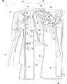
以下に、この発明を実施するための最良の形態について、図面を参照しつつ説明する。図1は、この発明の実施形態に係る帯電装置1を備えた画像形成装置100の構成を示す断面図である。画像形成装置100は、用紙(OHP等の記録媒体を含む。)に画像を形成する画像形成モードとして、コピアモード、プリンタモード、及びFAXモードを有し、各モードはユーザによって選択される。また、各モードでは、両面印刷が可能である。
The best mode for carrying out the present invention will be described below with reference to the drawings. FIG. 1 is a cross-sectional view illustrating a configuration of an
画像形成装置100は、原稿読取部10、給紙部20、画像形成部30、排紙部40、及び図示しない操作パネル部を備えている。
The
原稿読取部10は、装置本体の上部に配置され、プラテンガラス11、原稿載置トレイ12及びスキャナ光学系13を備えている。スキャナ光学系13は、光源14、反射ミラー15A〜15C、光学レンズ16及びCCD(Charge Coupled Device)17を有している。光源14は、プラテンガラス11に載置された原稿又は原稿載置トレイ12から原稿搬送路R上を搬送される原稿に光を照射する。反射ミラー15A〜15Cは、原稿からの反射光を反射させて光学レンズ16に導く。光学レンズ16は、反射ミラー15A〜15Cによって導かれた反射光をCCD17に結像する。CCD17は、反射光に応じた電気信号を出力する。
The
給紙部20は、装置本体の下部に配置され、給紙トレイ21及びピックアップローラ22を備えている。給紙トレイ21は、画像形成時に用紙搬送路S1に給紙すべき用紙を収容する。ピックアップローラ22は、回転して給紙トレイ21に載置された用紙を用紙搬送路S1に給紙する。
The
画像形成部30は、原稿読取部10の下方に配置され、レーザスキャニングユニット(以下、LSUと言う。)37、感光体ドラム31及び定着装置36を有している。感光体ドラム31の周囲には、帯電装置1、現像装置33、転写装置34及びクリーナユニット35が、感光体ドラム31の回転方向である図1に示す矢印の方向に沿ってこの順に配置されている。
The
排紙部40は、給紙トレイ21の上方に配置され、排紙ローラ41、排紙トレイ42を備えている。排紙ローラ41は、用紙搬送路S1上を搬送されてきた用紙を排紙トレイ42に排出する。排紙ローラ41は、可逆回転が可能であり、用紙の両面に画像形成を行う際、用紙搬送路S1上を搬送されてきた表面の画像形成が終了した用紙を挟持した状態で、上記用紙を排出する回転方向とは逆方向に回転して用紙搬送路S2へ搬送する。これにより、用紙の表裏面が反転されて裏面が感光体ドラム31に対向し、裏面にトナー画像の転写が行われる。排紙トレイ42は、排紙ローラ41から排出された用紙を積層して収容する。
The
操作パネル部に設けられたスタートキーが押下されると、画像形成装置100は、ピックアップローラ22を回転させて用紙搬送路S1へ用紙を給紙する。給紙された用紙は、用紙搬送路S1上に設けられたレジストローラ51へ搬送される。
When a start key provided on the operation panel unit is pressed, the
レジストローラ51は、用紙の先端部が到達した時には回転を停止している。レジストローラ51は、感光体ドラム31と転写装置34との間で感光体ドラム31上に形成されるトナー画像の先端部に、用紙の先端部が一致するタイミングで回転を開始する。
The
原稿読取部10によって読み取られた画像データは、操作パネル部から入力された条件で画像処理が施された後、LSU37にプリントデータとして送信される。LSU37は、帯電装置1によって所定の電位に帯電された感光体ドラム31の表面に、図示しないポリゴンミラー及び各種レンズを介して上記画像データに基づいたレーザ光を照射することで、静電潜像を形成する。その後、現像装置33に設けられたMGローラ33Aの表面に付着しているトナーが、感光体ドラム31の表面上の電位ギャップに応じて感光体ドラム31の表面に引き寄せられて付着し、静電潜像がトナー像に顕像化される。
The image data read by the
感光体ドラム31の表面のトナー像は、転写装置34によって用紙の表面に転写される。この転写工程後に感光体ドラム31の表面に残留したトナーは、クリーナユニット35によって回収される。
The toner image on the surface of the
転写工程を終了した用紙は、定着装置36を通過することで熱と圧力とを加えられ、用紙にトナー画像が溶融・固着される。用紙は、排紙ローラ41によって排紙トレイ42に排出される。
The paper that has completed the transfer process is subjected to heat and pressure by passing through the fixing
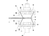
図2(A)は、帯電装置1の正面断面図であり、図2(B)は、帯電装置1の要部の側面図である。帯電装置1は、針電極2、ホルダ3、支持体4、清掃ローラ5、2個の掻き取り部材60、操作軸6、及びケース7を備えている。帯電装置1は、例えば感光体ドラム31の上方に配置される。
FIG. 2A is a front sectional view of the
針電極2は、薄い帯状の金属材料からなり、全長にわたって一定の間隔で下端部から複数の針2Aが下向きに延出している。複数の針2Aは、針電極2の長さ方向に平行な配列方向Xに沿って直線状に配列されている。帯電装置1は、針電極2の長手方向を感光体ドラム31の軸方向に平行にして配置される。したがって、配列方向Xは、感光体ドラム31の回転軸に平行である。針電極2の長さは、感光体ドラム31の周面の軸方向の長さよりも長い。
The
ホルダ3は、樹脂等の絶縁性材料によって構成されており、保持部3A及び端子部3Bを備えている。保持部3Aは、針電極2を保持する。保持部3Aの長さは、針電極2における複数の針2Aの配列範囲よりも長い。保持部3Aは、配列方向Xに直交する面内で、図2(A)中にハッチングで示す一定の断面形状を呈する。端子部3Bは、図示しない端子を内蔵している。端子は、図示しない高圧電源と針電極2とを接続する。
The
支持体4は、下面が開放しており、保持部3Aの外側に上方から装着されている。支持体4の内側面には、突起4A,4Bが形成されている。支持体4は、内側の上面と突起4A,4Bとの間に保持部3Aを上下方向に挟み、内側の側面で保持部3Aを左右方向に挟む。したがって、支持体4は、配列方向Xに直交する方向への回転を含む移動を規制されている。
The
清掃ローラ5は、この発明の第1清掃部材であり、軸体5Aに固定されている。軸体5Aは、複数の針2Aの配列方向Xに直交する方向に配置されている。軸体5Aの両端部のそれぞれは、支持体4の下端部に回転自在に支持されている。軸体5Aは、この発明の回転軸に相当する。
The cleaning
清掃ローラ5は、一例として、研磨剤を含有した弾性体である。研磨剤の硬度は、針電極2の素材よりも低く、トナー等の塵埃よりも高く設定されている。清掃ローラ5の周面から内部に針2Aの先端部が埋没する。研磨剤の硬度が針電極2の素材よりも低いので、清掃ローラ5に対して没入及び抜脱される際の針の摩耗が抑制される。
As an example, the cleaning
清掃ローラ5を構成する弾性体として、針2Aの没入及び抜脱によって容易に切断されることなく弾性変形することを条件に、公知のゴム材料や樹脂材料のなかから好適な材料を、実験を経て選択することができる。研磨剤は、針2Aの表面に損傷を与えることなく針2Aの表面からトナー等の塵埃を除去できることを条件に、公知の材料から適宜選択して使用することができ、公知の方法で弾性体に含有させることができる。
As an elastic body constituting the cleaning
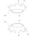
図3は、掻き取り部材60の正面図であり、図4は、掻き取り部材60の斜視図である。
FIG. 3 is a front view of the scraping
掻き取り部材60は、この発明の第2清掃部材であり、針電極2の素材と同等の硬度を有する薄板材で、薄肉中空のロール状に形成されている。掻き取り部材60は、一例として、0.3mm〜0.5mmの範囲内で選択された厚さのSUS材(SUS304又はSUS316等)で形成される。掻き取り部材60は、円錐台形の周面形状を呈しており、回転軸に沿う方向に小径側端部61及び大径側端部62を有している。掻き取り部材60が円錐台形の周面形状を呈する薄板材で形成されているので、小径側端部61は環状を呈している。
The scraping
掻き取り部材60は、大径側端部62近傍に、周方向に配列された複数のスリット63を有している。掻き取り部材62は、円錐台形の周面形状を呈するとともに周方向に配列された複数のスリット63を有することで、回転軸に沿う方向の弾力性を有している。
The scraping
2個の掻き取り部材60は、針電極2を挟んで小径側端部61が互いに対向し、清掃ローラ5と同軸上で回転するように清掃ローラ5の外周に配置されている。小径側端部61の内径は、清掃ローラ5の外径より若干大きくされている。
The two
大径側端部62は、固定部材64に固定されている。固定部材64は、円板部64Aと壁部64Bとを有している。壁部64Bは、円板部64Aの縁部から針電極2側へ突起している。大径側端部62は、壁部64Bの内側で円板部64Aに固定されている。円板部64Aは、軸体5Aを軸として回転自在にされている。即ち、掻き取り部材60は、固定部材64及び軸体5Aを介して支持体4に回転自在に支持されている。
The large diameter
固定部材64と支持体4との間に、緩衝材65が配置されている。緩衝材65の軸体5Aに沿う方向の大きさは、掻き取り部材60の小径側端部61が複数の針2Aのそれぞれの先端部の側面に圧接する大きさにされている。
A
図2(A)及び図2(B)に示すように、操作軸6は、背面側の端部が支持体4の孔部4Cの内部に固定されている。操作軸6は、図示しない前面側の端部がホルダ3の前面から突出している。
As shown in FIGS. 2A and 2B, the
ケース7は、ホルダ3の全長にわたって、支持体4の外側に装着される。ケース7は、針電極2をシールドする。
The
端子部3Bに収納された端子を介して針電極2に高圧電源が印加されると、針電極2の複数の針2Aのそれぞれの先端部に印加電界が集中し、この部分に放電を発生し易くなる。これによって、複数の針2Aのそれぞれから感光体ドラム31の表面に放電を生じる。この放電によって、感光体ドラム31の表面が、所定の電位に帯電する。
When a high voltage power supply is applied to the
保持部3Aの配列方向Xに直交する断面形状は、少なくとも複数の針2Aの配列範囲内で一定である。支持体4は、保持部3Aの外側に装着されて配列方向Xに直交する面内での回転を含む移動を規制されている。したがって、支持体4は、保持部3Aに案内されて、少なくとも複数の針2Aの配列範囲内で、配列方向Xに往復移動自在にされている。
The cross-sectional shape orthogonal to the arrangement direction X of the holding
図5は、清掃ローラ5の清掃動作を示す図である。図5では、掻き取り部材60は省略されている。支持体4に回転自在に支持された清掃ローラ5の周面に、針2Aの先端部が埋没する。支持体4が配列方向Xに沿って移動すると、清掃ローラ5も支持体4とともに移動する。このとき、清掃ローラ5の周面に複数の針2Aのそれぞれが順次埋没する。清掃ローラ5は、複数の針2Aから周面に作用する抵抗により、回転しつつ配列方向Xに沿って移動する。
FIG. 5 is a diagram illustrating a cleaning operation of the cleaning
清掃ローラ5は、針電極2と感光体ドラム31の周面との間に配置される。清掃ローラ5が配列方向Xに移動する際に、少なくとも1つの針2Aの先端部が常に清掃ローラ5の周面に埋没する。このため、清掃ローラ2は、配列方向Xに移動する際に確実に回転し、針2Aの先端部による清掃ローラ5の周面の損傷、及び、清掃ローラ5の周面による針2Aの変形が、最小限に抑えられる。
The cleaning
支持体4における清掃ローラ5の支持位置は、清掃ローラ5の周面に針2Aの先端から0.5mm程度の長さの先端部が埋没するように設定されている。清掃ローラ5が支持体4とともに配列方向Xに沿って移動すると、針2Aの先端部が先端から徐々に清掃ローラ5の内部に没入した後、徐々に抜脱されていく。この間に、針2Aの先端部の全面が清掃ローラ5を構成する弾性体に接触し、弾性体が含有する研磨剤によって研磨される。複数の針2Aの先端部が、針電極2の素材よりも低い硬度の研磨剤を含有した弾性体によって清掃されるので、清掃ローラ5に対して没入及び抜脱される際の針2Aの磨耗が抑制される。清掃ローラ5は複数の針2Aが順に没入及び抜脱される間に回転するので、少なくとも隣接する針2Aは、清掃ローラ5の周面の異なる位置に埋没する。これによって、針2Aの先端部の全面が、確実に清掃される。
The support position of the cleaning
図6は、掻き取り部材60の清掃動作を示す図である。図6では、清掃ローラ5は省略されている。
FIG. 6 is a diagram illustrating a cleaning operation of the scraping
針電極2の側面には、コロナ放電によって堆積した窒素酸化物等の固着物が強固に固着する。固着物は、フェルト等の柔らかい素材では十分に清掃できない。そこで、針電極2と同等の硬度を有する掻き取り部材60によって清掃する。
A fixed object such as nitrogen oxide deposited by corona discharge is firmly fixed to the side surface of the
支持体4に回転自在に支持された2個の掻き取り部材60の小径側端部61の間に、針2Aの先端部が埋没する。支持体4が配列方向Xに沿って移動すると、掻き取り部材60も支持体4とともに移動する。このとき、2個の掻き取り部材60の小径側端部61の間に複数の針2Aのそれぞれが順次埋没し、複数の針2Aのそれぞれの側面が順次、2個の掻き取り部材60のそれぞれの小径側端部61と圧接する。掻き取り部材60は、複数の針2Aから小径側端部61に作用する抵抗によって、回転しつつ配列方向Xに沿って移動する。
The distal end portion of the
掻き取り部材60の小径側端部61は、清掃ローラ5の周面に接触しない範囲でできるだけ近接するように形成されている。掻き取り部材60が配列方向Xに移動する際に、少なくとも1つの針2Aの先端部の側面が常に2個の掻き取り部材60のそれぞれの小径側端部61と圧接する。
The
掻き取り部材60が薄板材で形成されているので小径側端部61は環状を呈している。このため、小径側端部61のうち針2Aの側面に圧接する部分は、円弧状である。支持体4の移動時に、複数の針2Aのそれぞれの側面が小径側端部61と圧接する箇所は、複数の針2Aのそれぞれの先端側から基端側へ向かう第1方向Y1へ移動した後に、基端側から先端側へ向かう第2方向Y2へ移動する。これによって、複数の針2Aのそれぞれの側面に堆積した清掃ローラ5では落とし切れない固着物が、掻き取り部材60の小径側端部61の外周面及び内周面のそれぞれによって掻き落とされる。
Since the scraping
この際、小径側端部61は回転しながら針2Aの側面と圧接し、圧接する部分が第1方向Y1及び第2方向Y2へ移動するので、針2Aの側面に強固に固着した固着物は、掻き取り部材60によってより確実に掻き落とされる。
At this time, the small-
また、掻き取り部材60は、軸体5Aに沿う方向に弾性力を有しており、針2Aの側面に適度な力で圧接するので、針2Aの側面がより確実に清掃される。さらに、複数の針2Aのそれぞれの先端部は、掻き取り部材60によって両側面から挟み付けられるので、針2Aの変形が最小限に抑えられる。また、複数の針2Aの側面が、針電極2の素材と同等の硬度を有する素材によって摺擦されるので、各針2Aの側面に強固に固着した固着物がより確実に清掃される。したがって、針2Aの変形や繊維の付着を生じることなく、針2Aの先端部の全面が確実に清掃される。
Further, the scraping
さらに、掻き取り部材60が清掃ローラ5と同軸上で回転するように配置されているので、掻き取り部材60を清掃ローラ5と異なる位置に配置する場合と比べて省スペース化され、帯電装置1が小型化される。
Furthermore, since the scraping
図7は、帯電装置1の側面図である。帯電装置1は、上面側に操作軸6を備えている。操作軸6は、ホルダ3の略全長に匹敵する長さにされている。操作軸6の背面側の端部は、支持体4の孔部4Cに固定されている。ホルダ3の前端部には、装着部9が形成されている。装着部9は、端子部3Bと略同一の外形を呈する。装着部9の背面側には、軸受体8が固定されている。軸受体8は、支持体4と同一の部材が使用されており、上部に孔部4Cを備えている。装着部9の上面には軸受9Aが形成されている。
FIG. 7 is a side view of the
操作軸6は、軸受体8の孔部4C及び装着部9の軸受9を貫通している。操作軸6の前面側の端部には、把手6Aが装着されている。帯電装置1が、画像形成装置100内に装着されている状態で、端支部3A、軸受体8及び装着部9は、感光体ドラム31の表面における画像形成領域Wの外側の範囲に位置している。また、支持体4は、清掃を行っていない状態では、感光体ドラム31の表面における画像形成領域Wの外側の範囲内に設定された待機位置に位置している。このため、支持体4、端支部3A、軸受体8及び装着部9が感光体ドラム31の表面における画像形成の障害となることがない。
The
作業者は、帯電装置1の針電極2の清掃時に、把手6Aを摘んで操作軸6を配列方向Xに沿って往復移動させる。これによって、支持体4がホルダ3の支持部3Aに案内されて配列方向Xに沿って往復移動し、支持体4に支持された清掃ローラ5が回転しつつ表面に針電極2の複数の針2Aを順に表面に埋没させていくとともに、支持体4に支持された掻き取り部材60が回転しつつ小径側端部61を複数の針2Aの側面に圧接していく。
When cleaning the
針電極2の複数の針2Aの先端部が順に清掃ローラ5の内部に没入及び抜脱する時に、各針2Aの先端部の全面が清掃ローラ5に接触する。また、掻き取り部材60の小径側端部61が複数の針2Aの先端部の側面に順に圧接する時に、各針2Aの先端部の側面が小径側端部61に摺擦される。したがって、針2Aの変形や繊維の付着を生じることなく、針2Aの先端部の全面が確実に清掃される。
When the tips of the plurality of
また、操作軸6は、支持体4、軸受体8及び軸受9Aの3点で支持されている。このため、操作軸6を配列方向Xに沿って円滑に往復動作させることができる。
The
清掃部材として必ずしも清掃ローラ5を用いる必要はなく、支持体4に回転自在に支持される回転体であればよい。
The cleaning
掻き取り部材60は、円錐台形の周面形状であることに限定されず、円筒形等の他の薄肉中空のロール状であってもよい。また、掻き取り部材60は、中空であることに限定されず、円柱形や円錐台形等の中実形状であってもよい。さらに、掻き取り部材60は、回転軸方向の一方の端部が複数の針2Aのそれぞれの側面に順次圧接する限りにおいて、清掃ローラ5と異なる軸上で回転するように配置されてもよい。また、掻き取り部材60は、3個以上備えられていてもよい。
The scraping
最後に、上述の実施形態の説明は、すべての点で例示であって、制限的なものではないと考えられるべきである。本発明の範囲は、上述の実施形態ではなく、特許請求の範囲によって示される。さらに、本発明の範囲には、特許請求の範囲と均等の意味および範囲内でのすべての変更が含まれることが意図される。 Finally, the description of the above-described embodiment is to be considered in all respects as illustrative and not restrictive. The scope of the present invention is shown not by the above embodiments but by the claims. Furthermore, the scope of the present invention is intended to include all modifications within the meaning and scope equivalent to the scope of the claims.
1 帯電装置
2 針電極
2A 針
3 ホルダ
3A 保持部
4 支持体
5 清掃ローラ(第1清掃部材)
5A 軸体(回転軸)
6 操作軸
31 感光体ドラム(感光体)
60 掻き取り部材(第2清掃部材)
61 小径側端部
62 大径側端部
63 スリット
65 軸体(回転軸)
100 画像形成装置
X 配列方向
DESCRIPTION OF
5A Shaft (Rotating shaft)
6
60 Scraping member (second cleaning member)
61 Small-diameter side end 62 Large-diameter side end 63
100 Image forming apparatus X Array direction
Claims (8)
前記配列方向に沿って移動自在に配置された支持体と、
前記複数の針のうちの少なくとも1個の針の先端部に対向する周面を有して前記支持体に回転自在に支持された第1清掃部材であって、前記支持体の移動時に、前記配列方向に沿って回転しながら移動し、前記複数の針のそれぞれの先端部が順に前記周面から内部に埋没した後に前記内部から露出する第1清掃部材と、
前記配列方向に直交する方向の回転軸を中心に回転自在に前記支持体に支持された第2清掃部材であって、前記支持体の移動時に、前記配列方向に沿って回転しながら移動し、前記回転軸に沿う方向の一方の端部が前記複数の針のそれぞれの側面に順に圧接する第2清掃部材と、を備える帯電装置。 A needle electrode having a plurality of needles arranged linearly along a predetermined arrangement direction;
A support body arranged to be movable along the arrangement direction;
A first cleaning member having a peripheral surface facing the tip of at least one of the plurality of needles and rotatably supported by the support, wherein the support is moved when the support is moved. A first cleaning member that moves while rotating along the arrangement direction, and is exposed from the inside after the respective distal end portions of the plurality of needles are buried in the inside from the peripheral surface in order,
A second cleaning member supported by the support so as to be rotatable about a rotation axis in a direction perpendicular to the arrangement direction, and moving while rotating along the arrangement direction when the support is moved; A charging device comprising: a second cleaning member in which one end portion in a direction along the rotation axis is in pressure contact with each side surface of the plurality of needles in order.
前記複数の針が前記感光体の表面に対向するように配置された請求項1から7のいずれかに記載の帯電装置を備える画像形成装置。 An image forming apparatus that performs electrophotographic image forming processing via a photoreceptor,
An image forming apparatus comprising the charging device according to claim 1, wherein the plurality of needles are arranged to face the surface of the photoconductor.
Priority Applications (1)
| Application Number | Priority Date | Filing Date | Title |
|---|---|---|---|
| JP2007262965A JP2009092902A (en) | 2007-10-09 | 2007-10-09 | Charging device and image forming apparatus |
Applications Claiming Priority (1)
| Application Number | Priority Date | Filing Date | Title |
|---|---|---|---|
| JP2007262965A JP2009092902A (en) | 2007-10-09 | 2007-10-09 | Charging device and image forming apparatus |
Publications (1)
| Publication Number | Publication Date |
|---|---|
| JP2009092902A true JP2009092902A (en) | 2009-04-30 |
Family
ID=40664959
Family Applications (1)
| Application Number | Title | Priority Date | Filing Date |
|---|---|---|---|
| JP2007262965A Pending JP2009092902A (en) | 2007-10-09 | 2007-10-09 | Charging device and image forming apparatus |
Country Status (1)
| Country | Link |
|---|---|
| JP (1) | JP2009092902A (en) |
Cited By (8)
| Publication number | Priority date | Publication date | Assignee | Title |
|---|---|---|---|---|
| JP2011003521A (en) * | 2009-05-19 | 2011-01-06 | Sharp Corp | Electron emitting element, electron emitting device, self light-emitting device, image display, blower, cooling device, electrically-charged device, image forming device, electron-beam curing device, and method for manufacturing electron emitting element |
| US8249487B2 (en) | 2009-05-19 | 2012-08-21 | Sharp Kabushiki Kaisha | Electron emitting element, electron emitting device, charging device, image forming apparatus, electron-beam curing device, light emitting device, image display device, air blowing device, and cooling device |
| US8299700B2 (en) | 2009-02-05 | 2012-10-30 | Sharp Kabushiki Kaisha | Electron emitting element having an electron acceleration layer, electron emitting device, light emitting device, image display device, cooling device, and charging device |
| US8378565B2 (en) | 2009-06-25 | 2013-02-19 | Sharp Kabushiki Kaisha | Electron emitting element having an electron acceleration layer using fine particle layer |
| US8401430B2 (en) | 2007-11-20 | 2013-03-19 | Sharp Kabushiki Kaisha | Electron emitting element for accelerating and emitting electrons, and use of electron emitting element |
| US8476818B2 (en) | 2009-05-19 | 2013-07-02 | Sharp Kabushiki Kaisha | Electron emitting element including a fine particle layer containing insulating particles, and devices and methods related thereto |
| US8487521B2 (en) | 2009-12-01 | 2013-07-16 | Sharp Kabushiki Kaisha | Electron emitting element, method for producing electron emitting element, electron emitting device, charging device, image forming apparatus, electron-beam curing device, light emitting device, image display device, air blowing device, and cooling device |
| US8547007B2 (en) | 2009-02-24 | 2013-10-01 | Sharp Kabushiki Kaisha | Electron emitting element, electron emitting device, light emitting device, image display device, air blowing device, cooling device, charging device, image forming apparatus, electron-beam curing device, and method for producing electron emitting element |
-
2007
- 2007-10-09 JP JP2007262965A patent/JP2009092902A/en active Pending
Cited By (9)
| Publication number | Priority date | Publication date | Assignee | Title |
|---|---|---|---|---|
| US8401430B2 (en) | 2007-11-20 | 2013-03-19 | Sharp Kabushiki Kaisha | Electron emitting element for accelerating and emitting electrons, and use of electron emitting element |
| US8299700B2 (en) | 2009-02-05 | 2012-10-30 | Sharp Kabushiki Kaisha | Electron emitting element having an electron acceleration layer, electron emitting device, light emitting device, image display device, cooling device, and charging device |
| US8547007B2 (en) | 2009-02-24 | 2013-10-01 | Sharp Kabushiki Kaisha | Electron emitting element, electron emitting device, light emitting device, image display device, air blowing device, cooling device, charging device, image forming apparatus, electron-beam curing device, and method for producing electron emitting element |
| US8616931B2 (en) | 2009-02-24 | 2013-12-31 | Sharp Kabushiki Kaisha | Electron emitting element, electron emitting device, light emitting device, image display device, air blowing device, cooling device, charging device, image forming apparatus, electron-beam curing device, and method for producing electron emitting element |
| JP2011003521A (en) * | 2009-05-19 | 2011-01-06 | Sharp Corp | Electron emitting element, electron emitting device, self light-emitting device, image display, blower, cooling device, electrically-charged device, image forming device, electron-beam curing device, and method for manufacturing electron emitting element |
| US8249487B2 (en) | 2009-05-19 | 2012-08-21 | Sharp Kabushiki Kaisha | Electron emitting element, electron emitting device, charging device, image forming apparatus, electron-beam curing device, light emitting device, image display device, air blowing device, and cooling device |
| US8476818B2 (en) | 2009-05-19 | 2013-07-02 | Sharp Kabushiki Kaisha | Electron emitting element including a fine particle layer containing insulating particles, and devices and methods related thereto |
| US8378565B2 (en) | 2009-06-25 | 2013-02-19 | Sharp Kabushiki Kaisha | Electron emitting element having an electron acceleration layer using fine particle layer |
| US8487521B2 (en) | 2009-12-01 | 2013-07-16 | Sharp Kabushiki Kaisha | Electron emitting element, method for producing electron emitting element, electron emitting device, charging device, image forming apparatus, electron-beam curing device, light emitting device, image display device, air blowing device, and cooling device |
Similar Documents
| Publication | Publication Date | Title |
|---|---|---|
| JP2009092902A (en) | Charging device and image forming apparatus | |
| JP4436815B2 (en) | Charging device and image forming apparatus | |
| JP5901227B2 (en) | Charging member and image forming apparatus | |
| JP4216301B2 (en) | Charging device | |
| US7769313B2 (en) | Charging device and image forming apparatus | |
| JP2008026646A (en) | Charging device, image forming apparatus and conveying screw mechanism | |
| JP5512573B2 (en) | Charging device and image forming apparatus | |
| US20070177914A1 (en) | Wet electrophotographic apparatus | |
| JP4241770B2 (en) | Charging device | |
| JP4898643B2 (en) | Charging device and image forming apparatus | |
| JP5574694B2 (en) | Image forming apparatus | |
| JP2008026739A (en) | Charging device | |
| CN100510999C (en) | Electrification device and image forming apparatus | |
| JP4062503B2 (en) | Corona discharge device and image forming apparatus having the same | |
| JP5256242B2 (en) | Charging device and image forming apparatus having the same | |
| JP6041718B2 (en) | Charging device and image forming apparatus | |
| JP2008064955A (en) | Charging device and image forming apparatus | |
| JPH05341588A (en) | Image forming device and processing cartridge | |
| JP4230495B2 (en) | Charging device | |
| JP2008032854A (en) | Charging device and image forming device | |
| JP4696676B2 (en) | Corona discharge device, process cartridge, and image forming apparatus | |
| JP5583522B2 (en) | Developing device and image forming apparatus having the same | |
| JP2005242260A (en) | Electrostatic charging device for carrier member, carrier device and image forming device | |
| JPH07261518A (en) | Cleaning device for electrifying roller | |
| JP4062532B2 (en) | Corona discharge device and image forming apparatus having the same |