JP2009092514A - Sample liquid assay chip and transfer control method of sample liquid - Google Patents
Sample liquid assay chip and transfer control method of sample liquid Download PDFInfo
- Publication number
- JP2009092514A JP2009092514A JP2007263478A JP2007263478A JP2009092514A JP 2009092514 A JP2009092514 A JP 2009092514A JP 2007263478 A JP2007263478 A JP 2007263478A JP 2007263478 A JP2007263478 A JP 2007263478A JP 2009092514 A JP2009092514 A JP 2009092514A
- Authority
- JP
- Japan
- Prior art keywords
- sample liquid
- electrode pair
- electrode
- sample
- transfer path
- Prior art date
- Legal status (The legal status is an assumption and is not a legal conclusion. Google has not performed a legal analysis and makes no representation as to the accuracy of the status listed.)
- Withdrawn
Links
Images


Landscapes
- Automatic Analysis And Handling Materials Therefor (AREA)
Abstract
Description
本発明は、試料液を分析する試料液分析チップ、およびこの試料液分析チップにおける試料液の移送制御方法に関する。 The present invention relates to a sample liquid analysis chip for analyzing a sample liquid, and a sample liquid transfer control method in the sample liquid analysis chip.
近年、分析・解析・検査技術の進歩によって、様々な物質の測定が可能となっている。特に、臨床検査分野では、生化学反応や酵素反応、免疫反応などの特異的な反応に基づく測定原理が開発され、病態に反映する体液中の物質を測定することができる。 In recent years, various substances can be measured by advances in analysis, analysis, and inspection techniques. In particular, in the clinical laboratory field, measurement principles based on specific reactions such as biochemical reactions, enzyme reactions, and immune reactions have been developed, and substances in body fluids that reflect disease states can be measured.
現在、その臨床検査分野において、ポイント・オブ・ケアテスティング(POCT)と呼ばれる臨床検査が注目されている。POCTとは、患者の近いところで行われる簡易迅速検査を意味し、簡易な測定原理を採用することによって短時間のうちに試料液中の特定成分を定量する。POCTでは、主に測定原理として、酵素反応や抗原抗体反応などの生化学反応を採用している。酵素や抗体は、その反応相対物質を選択的に認知する反応特異性が非常に高いだけでなく反応効率も高いことから、高感度で試料液中の分析対象成分を測定できるためである。 Currently, in the field of clinical testing, a clinical test called point of care testing (POCT) is drawing attention. POCT means a simple rapid test performed near a patient, and a specific component in a sample solution is quantified in a short time by adopting a simple measurement principle. POCT mainly employs biochemical reactions such as enzyme reactions and antigen-antibody reactions as the measurement principle. This is because enzymes and antibodies not only have a very high reaction specificity for selectively recognizing the reaction relative substances but also have a high reaction efficiency, so that the analyte components in the sample solution can be measured with high sensitivity.
POCTは、一般的に試料液分析チップを用いて行われる。試料液分析チップとは、任意の測定原理を採用することによって液状の検体である試料液を分析できる微小な測定部材であり、例えば、バイオセンサやコレステロールセンサなどに適用される。現在、POCTでは、測定手順を簡易にし、かつ検体を採取してから検査結果が出るまでの時間の短縮を目的とした検査方法の実現に向けて様々な検討が行われている。それに伴って、試料液分析チップには、小型で携帯可能であること、簡易な測定原理を採用することによって操作が容易で、かつ高精度分析が可能であることなどの機能が求められている。そのため、現在、これらの要望を実現させた試料液分析チップを提供するための様々な検討が行われている。 POCT is generally performed using a sample solution analysis chip. The sample liquid analysis chip is a minute measurement member that can analyze a sample liquid that is a liquid specimen by adopting an arbitrary measurement principle, and is applied to, for example, a biosensor or a cholesterol sensor. At present, in POCT, various studies are being carried out to realize a test method that simplifies the measurement procedure and shortens the time from when a sample is collected until the test result is obtained. Along with this, the sample liquid analysis chip is required to have functions such as being small and portable and adopting a simple measurement principle to facilitate operation and enable high-precision analysis. . Therefore, various studies are currently being conducted to provide a sample solution analysis chip that realizes these demands.
そこで、簡易迅速を可能とする試料液分析チップとして、例えば、スクリーン印刷などによって少なくとも測定極と対極とからなる電極対を設けた絶縁性の基板と、この電極対の表面に設けられた酸化還元酵素、および親水性高分子を含む酵素層と、電子受容体層とを有するバイオセンサが提案されている(例えば、特許文献1参照)。このバイオセンサでは、基質を含む試料液を酵素層へ滴下して酵素と基質とを反応させることにより、電子受容体を還元する。この酵素反応が終了した後に、還元された電子受容体を電気化学的に酸化するときに、測定される酸化電流値に基づいて、試料液中の基質濃度を求めるものである。このバイオセンサは、例えば、グルコースを基質としたグルコースセンサとして有用であるが、グルコース以外にも様々な基質の定量に広く利用されている。 Therefore, as a sample liquid analysis chip that enables simple and rapid, for example, an insulating substrate provided with an electrode pair consisting of at least a measurement electrode and a counter electrode by screen printing or the like, and an oxidation-reduction provided on the surface of this electrode pair A biosensor having an enzyme layer containing an enzyme and a hydrophilic polymer and an electron acceptor layer has been proposed (see, for example, Patent Document 1). In this biosensor, the electron acceptor is reduced by dropping a sample solution containing a substrate onto the enzyme layer and reacting the enzyme with the substrate. When the reduced electron acceptor is electrochemically oxidized after the completion of the enzyme reaction, the substrate concentration in the sample solution is obtained based on the measured oxidation current value. This biosensor is useful, for example, as a glucose sensor using glucose as a substrate, but is widely used for quantification of various substrates other than glucose.
ところで、POCTでは、場合によっては複数の試薬を必要とする。このとき、従来は、予め、試料液分析チップ内に複数の試薬を混合した状態で保存していたが、試薬の特性が変化するなどして分析制度が低下するなどの問題が生じていた。そこで、複数の試薬を安定して保存できる、すなわち保存安定性が高い試料液分析チップとして、例えば、酵素および界面活性剤を含む試薬と電子受容体を含む試薬とを分けて配置することにより、各試薬の保存安定性を向上させたコレステロールセンサが提案されている(例えば、特許文献2参照)。また、酵素および界面活性剤を含む試薬と電子受容体を含む試薬とを分けて配置するコレステロールセンサなどが示されている(例えば、特許文献3参照)。 By the way, POCT requires a plurality of reagents in some cases. At this time, conventionally, a plurality of reagents are mixed and stored in advance in the sample solution analysis chip. However, there is a problem that the analysis system is lowered due to a change in the characteristics of the reagents. Therefore, as a sample solution analysis chip that can stably store a plurality of reagents, that is, high storage stability, for example, by separately arranging a reagent containing an enzyme and a surfactant and a reagent containing an electron acceptor, A cholesterol sensor with improved storage stability of each reagent has been proposed (see, for example, Patent Document 2). In addition, a cholesterol sensor or the like in which a reagent containing an enzyme and a surfactant and a reagent containing an electron acceptor are arranged separately is shown (for example, see Patent Document 3).
ただし、特許文献2、3に示された技術のように、複数の試薬を別々に配置すれば、各試薬の保存安定性の高さは保たれるが、複数の試薬を微小な反応領域に送り、そこで各試薬と試料液とを一度に混ぜた場合、試料液と各試薬とを混合するのに長時間要するという問題がある。また、試料液の流れに沿って試薬A、Bを順に配置した場合には、試料液中の試薬濃度にバラツキが生じてしまい、全体的に均一な試料液を得ることが難しい。反応領域において試料液と試薬とを十分に反応させなければ、結果として分析精度が低下する。そのため、試料液分析チップでは、試料液の移送を好適に制御することが重要である。 However, as in the techniques shown in Patent Documents 2 and 3, if a plurality of reagents are arranged separately, the storage stability of each reagent is maintained, but the plurality of reagents are placed in a minute reaction region. When the reagent and the sample solution are mixed at once, there is a problem that it takes a long time to mix the sample solution and each reagent. Further, when the reagents A and B are arranged in order along the flow of the sample solution, the reagent concentration in the sample solution varies, and it is difficult to obtain a uniform sample solution as a whole. If the sample solution and the reagent are not sufficiently reacted in the reaction region, the analysis accuracy is lowered as a result. Therefore, it is important for the sample solution analysis chip to appropriately control the transfer of the sample solution.
試料液の移送を制御する方法としては、毛細管現象を利用する方法が知られている。毛細管現象とは、試料液が移送される管内にて、管の内壁面と試料液との間に働く吸引力によって試料液が移動する現象である。例えば、特許文献3には、クロマトグラフ媒体として多孔質の吸水性物質を使用し、毛細管現象によって試料液を移送するイムノクロマトグラフ法用の分析チップが提案されている。イムノクロマトグラフ法とは、抗体が固定されたクロマトグラフ担体に試料液を流して、その抗体と被検知物質とを結合させる、すなわち抗原抗体反応を利用した分析方法である。 As a method for controlling the transfer of the sample liquid, a method utilizing capillary action is known. The capillary phenomenon is a phenomenon in which the sample liquid moves by a suction force acting between the inner wall surface of the pipe and the sample liquid in the pipe to which the sample liquid is transferred. For example, Patent Document 3 proposes an analysis chip for an immunochromatographic method that uses a porous water-absorbing substance as a chromatographic medium and transfers a sample solution by capillary action. The immunochromatography method is an analysis method using an antigen-antibody reaction, in which a sample solution is passed through a chromatographic carrier on which an antibody is immobilized, and the antibody and a substance to be detected are bound.
さらに、核酸の高処理量シークエンシングの方法において、遠心力、あるいは遠心力と毛細管現象とを組み合わせて試料液の移送を制御する方法が提案されている。その他にも、流路に設けた電極に電圧を印加し、試料液の電極表面に対する表面張力を低下させることにより流体を移送する方法も提案されている(例えば、特許文献4参照)。このような方法はエレクトロウエッティング現象を利用した方法とも呼ばれ、例えば、化学的アッセイなどにおいて、2次元に配列された電極を有するマイクロ流体構造を用いて、液滴を2次元的に任意に移動させる機構が提案されている(例えば、特許文献5参照)。エレクトロウエッティング現象を用いる方法は、機構が単純でありながら、試料液を効率よくかつ効果的に移送できる。また、試料液の移送に用いる電極は、試料液と試薬との反応を検出するための測定用電極として用いることもできるので便利である。
以上の通り、POCTに適した試料液分析チップとしては、簡易構造でありながら、試薬の保存安定性が高く、かつ試料液の移送を好適に制御できるものが有用である。また、試料液と試薬との反応を高感度で検出できる分析精度の高さが重要であることはいうまでもない。 As described above, a sample solution analysis chip suitable for POCT is useful because it has a simple structure but has high reagent storage stability and can suitably control the transfer of the sample solution. Needless to say, it is important to have high analytical accuracy capable of detecting the reaction between the sample solution and the reagent with high sensitivity.
試薬の保存安定性を高めるには、複数の反応領域を設置するなど、各試薬を別の領域に保存することが有効である。また、試薬同士が混ざり合わないように、各試薬を隔離して設置することが望ましい。ただし、複数の試薬を分けて保存しても、1つの反応領域にすべての試薬を流入させると、試料液と試薬とを混合した溶液の試薬の濃度分布にばらつきが生じてしまう。 In order to increase the storage stability of the reagent, it is effective to store each reagent in a separate area, such as installing a plurality of reaction areas. In addition, it is desirable to install each reagent separately so that the reagents do not mix with each other. However, even if a plurality of reagents are stored separately, if all the reagents are allowed to flow into one reaction region, the concentration distribution of the reagent in the solution in which the sample solution and the reagent are mixed will vary.
そこで、上記のばらつきを改善するためには、各試薬が保存された個々の領域に試料液を段階的に流入させる構造とすればよい。ところが、複数の反応領域や検出領域を分けて配置したとしても、反応領域から反応領域へ、あるいは反応領域から検出領域への試料液の移送を制御できない場合がある。例えば、反応領域に試料液を長時間滞留させると、過剰の試薬が試料液中に溶解するため、試料液が過飽和となる。このような試料液は、試薬の濃度が不均一であるから、測定誤差が大きくなり分析精度は著しく低下する。そのため、試料液を単に移動させるだけでなく、試料液の移送の停止/開始を任意に制御できる方法の確立が望まれる。 Therefore, in order to improve the above-described variation, a structure may be adopted in which the sample solution is allowed to flow stepwise into each region where each reagent is stored. However, even if a plurality of reaction regions and detection regions are arranged separately, the transfer of sample liquid from the reaction region to the reaction region or from the reaction region to the detection region may not be controlled. For example, if the sample solution is allowed to stay in the reaction region for a long time, the excess reagent is dissolved in the sample solution, so that the sample solution becomes supersaturated. In such a sample solution, since the concentration of the reagent is not uniform, the measurement error becomes large and the analysis accuracy is remarkably lowered. Therefore, it is desired to establish a method capable of arbitrarily controlling the stop / start of the transfer of the sample liquid as well as simply moving the sample liquid.
しかし、試料液を移送する方法として、例えば、特許文献3のように多孔質吸水性物質による毛細管現象を利用する方法では、毛細管現象は試料液の自発的な移動であるから、試料液の移送をいったん停止させてから、再び開始するというような任意に移送を制御することは難しい。そのため、試料液と試薬との反応に必要な時間、試料液を反応領域に留めた後、検出領域に移送するなどの制御が不可能である。
一方、特許文献4のように遠心力、あるいは遠心力と毛細管現象を組み合わせて、試料液の移送を制御する方法では、遠心力を得るための回転機構が必要となるので、装置が複雑になる。また、試料液分析チップを遠心力に耐えうる強度に設計する必要が生じるため、チップの形状、材質が制限される。
However, as a method for transferring the sample liquid, for example, in a method using a capillary phenomenon due to a porous water-absorbing substance as in Patent Document 3, the capillary phenomenon is a spontaneous movement of the sample liquid. It is difficult to control the transfer arbitrarily, such as stopping and then starting again. Therefore, it is impossible to control the sample solution for a time required for the reaction between the sample solution and the reagent, for example, after the sample solution is kept in the reaction region and then transferred to the detection region.
On the other hand, in the method of controlling the transfer of the sample liquid by combining the centrifugal force or the centrifugal force and the capillary phenomenon as in Patent Document 4, a rotation mechanism for obtaining the centrifugal force is required, so that the apparatus is complicated. . In addition, since it is necessary to design the sample liquid analysis chip to have a strength that can withstand centrifugal force, the shape and material of the chip are limited.
また、特許文献5のようにエレクトロウエッティング現象を用いる方法では、試料液の移送路内に電極を露出させるなどして導電性を充分に確保した場合であっても、試料液を移送するために数V程度の電圧を必要とする。この場合、試料液中の成分によっては、移送時の電極に対する通電によって酸化還元反応が生じて、試料液と試薬との反応を検出するための化学反応と区別することができないおそれがある。これでは、酵素を試薬とし、この酵素と試料液との酸化還元反応による電子移動を検出するような試料液分析チップに適用することが困難である。このような電極近傍での酸化還元反応を抑制するために、試料液の移送用にかかる面積が大きい電極の表面に、誘電体の薄膜を形成する手段が一般的に知られている。しかし、この場合に電極にかける電圧は、数十V、あるいはそれ以上を必要とするため、大掛かりな装置となり、簡易測定を目的とするPOCTに適用するには有用であるとは言い難い一面があった。 Further, in the method using the electrowetting phenomenon as in Patent Document 5, even when the conductivity is sufficiently ensured by exposing an electrode in the sample liquid transfer path, the sample liquid is transferred. Voltage of about several volts is required. In this case, depending on the components in the sample solution, an oxidation-reduction reaction may occur due to energization of the electrode during transfer, and may not be distinguished from a chemical reaction for detecting the reaction between the sample solution and the reagent. This makes it difficult to apply to a sample solution analysis chip that uses an enzyme as a reagent and detects electron transfer due to an oxidation-reduction reaction between the enzyme and the sample solution. In order to suppress such an oxidation-reduction reaction in the vicinity of the electrode, means for forming a dielectric thin film on the surface of the electrode having a large area for transferring the sample liquid is generally known. However, since the voltage applied to the electrode in this case requires several tens of volts or more, it becomes a large-scale device, and it is difficult to say that it is useful for application to POCT for the purpose of simple measurement. there were.
そこで、本発明は、上記課題を解決するためになされたものであり、簡易な構造でありながら複数の試薬の保存安定性が高く、かつ必要に応じて停止、および移動を含む試料液の移送制御が可能な試料液分析チップを提供することを目的とする。さらに本発明は、当該試料液分析チップを用いた試料液の移送制御方法を提供することを目的とする。 Therefore, the present invention has been made to solve the above-described problems, and has a simple structure and high storage stability of a plurality of reagents, and also includes transfer of a sample solution including stopping and moving as necessary. An object of the present invention is to provide a controllable sample liquid analysis chip. A further object of the present invention is to provide a sample liquid transfer control method using the sample liquid analysis chip.
本発明者らは、反応領域と検出領域との設置条件、および試料液の移送を制御する方法として、毛細管現象とエレクトロウエッティング現象とに着眼し、これらを組み合わせることにより本発明を完成させた。 The present inventors have completed the present invention by focusing on the capillary phenomenon and the electrowetting phenomenon as a method for controlling the installation conditions of the reaction region and the detection region and the transfer of the sample liquid, and combining them. .
すなわち、上記課題は、本発明の試料液分析チップによって解決される。
[1] 電気絶縁性の基板と、前記基板上に形成された1対の電極を2組以上含む電極系と、スペーサを介して前記基板と貼り合わされた電気絶縁性のカバーと、前記基板と前記カバーとの間において前記スペーサにより規定された管状の流路であって、試料液の流入口および前記流入口とは反対側に設けられた空気口を有する試料液移送路と、前記基板上の試料液移送路内に形成された、反応試薬層が配置された1つまたは2つ以上の反応試薬領域、および前記試料液の物理的あるいは光学的変化を検出する検出領域と、前記流入口を含む前記基板上に形成された試料液の供給部であって、前記試料液供給部に供給された試料液が、毛細管現象によって前記流入口から前記試料液移送路内へと吸引される供給部と、を備える試料液分析チップであって、前記電極系は、前記流入口近傍に配置された第一の電極対と、前記第一の電極対に隣接した第二の電極対とを含み、前記第一の電極対を構成する電極の一部分は、前記流入口から前記試料液移送路の外側に形成されており、前記第二の電極対は、前記第一の電極対よりも前記試料液移送路の空気口側に形成されており、さらに、3組以上のN組(N=3、4、5・・・)の電極対を配置する場合には、N組目の電極対が、(N−1)組目の電極対よりも前記試料液供給路内の空気口側において(N−1)組目の電極対と隣接して配置され、前記電極対を構成する電極は、前記試料液移送路について対称であって、少なくともその一部分が、前記試料液供給部において試料液が供給される領域、あるいは前記試料液移送路内に配置され、かつ前記反応試薬領域には配置されない試料液分析チップ。
[2] 前記電極対を構成する電極の、前記試料液移送路の中央側の下流端部が、前記試料液移送路の下流側に向かって突出しており、前記試料液移送路に沿って隣接する電極同士は、前記試料液移送路の移送方向に対して鋭角をなす方向に延びる溝を介して分離されている[1]に記載の試料液分析チップ。
[3] 前記反応試薬層が、酸化還元酵素と電子メディエータとを含み、前記検出領域が、前記反応試薬領域よりも前記試料液移送路内の前記空気口側に配置されている[1]または[2]に記載の試料液分析チップ。
[4] 前記検出領域は、前記基板の表面に配置され、測定極と対極とから構成された測定用電極対を含み、前記測定極は、前記検出領域の中央部に配置され、前記測定極の幅が前記試料液移送路の幅よりも狭い[3]に記載の試料液分析チップ。
[5] 前記測定極が、前記反応試薬層で覆われている[4]に記載の試料液分析チップ。
[6] 前記基板、または前記カバーのうち、少なくとも前記検出領域となりうる領域が、光透過性を持つ材料で形成されている[1]から[5]いずれかに記載の試料液分析チップ。
[7] 前記試料液移送路内において、隣接した前記電極対同士の境界部付近に、前記試料液先端の位置を感知する感知領域が配置されている[1]から[6]いずれかに記載の試料液分析チップ。
That is, the above problem is solved by the sample liquid analysis chip of the present invention.
[1] An electrically insulating substrate, an electrode system including two or more pairs of electrodes formed on the substrate, an electrically insulating cover bonded to the substrate through a spacer, and the substrate A tubular flow path defined by the spacer between the cover and a sample liquid inlet having a sample liquid inlet and an air port provided on the opposite side of the inlet; and on the substrate One or two or more reaction reagent regions in which a reaction reagent layer is disposed, a detection region for detecting a physical or optical change of the sample solution, and the inlet A sample liquid supply unit formed on the substrate, wherein the sample liquid supplied to the sample liquid supply unit is sucked from the inlet into the sample liquid transfer path by capillary action And a sample solution analysis chip comprising The electrode system includes a first electrode pair disposed in the vicinity of the inflow port and a second electrode pair adjacent to the first electrode pair, and constitutes the first electrode pair. A part of the electrode is formed outside the sample liquid transfer path from the inlet, and the second electrode pair is formed closer to the air port side of the sample liquid transfer path than the first electrode pair. Further, when arranging three or more N pairs (N = 3, 4, 5...) Of electrode pairs, the Nth electrode pair is the (N−1) th set. The electrodes constituting the electrode pair are arranged symmetrically with respect to the sample liquid transfer path, and are arranged adjacent to the (N-1) th electrode pair on the air port side in the sample liquid supply path with respect to the electrode pair. And at least a part of the sample liquid is disposed in the sample liquid supply section in the region where the sample liquid is supplied, or in the sample liquid transfer path. And the sample liquid analysis chip not placed on a reagent area.
[2] The downstream end of the electrode constituting the electrode pair on the center side of the sample liquid transfer path protrudes toward the downstream side of the sample liquid transfer path, and is adjacent along the sample liquid transfer path The sample solution analysis chip according to [1], wherein the electrodes to be separated are separated through a groove extending in a direction that forms an acute angle with respect to the transfer direction of the sample solution transfer path.
[3] The reaction reagent layer includes an oxidoreductase and an electron mediator, and the detection region is disposed closer to the air inlet side in the sample liquid transfer path than the reaction reagent region [1] or The sample liquid analysis chip according to [2].
[4] The detection region includes a measurement electrode pair that is disposed on a surface of the substrate and includes a measurement electrode and a counter electrode, and the measurement electrode is disposed in a central portion of the detection region, and the measurement electrode The sample liquid analysis chip according to [3], wherein the width of is narrower than the width of the sample liquid transfer path.
[5] The sample liquid analysis chip according to [4], wherein the measurement electrode is covered with the reaction reagent layer.
[6] The sample liquid analysis chip according to any one of [1] to [5], wherein at least a region that can be the detection region of the substrate or the cover is formed of a light-transmitting material.
[7] In any one of [1] to [6], in the sample solution transfer path, a sensing region for detecting the position of the tip of the sample solution is arranged in the vicinity of a boundary portion between the adjacent electrode pairs. Sample liquid analysis chip.
また、上記課題は、本発明の試料液の移送制御方法によって解決される。
[8] [1]に記載の試料液分析チップを準備する工程と、前記第一の電極対および前記第二の電極対と少なくとも部分的に重なるように試料液を滴下する工程と、前記試料液が部分的に重なった前記第一の電極対に対して、前記第二の電極対の電圧よりも大きい電圧をかける工程と、を有し、さらに、3組以上のN組(N=3、4、5・・・)の電極対を配置する場合には、前記試料液移送路内において、前記試料液の流れに沿って隣接した任意の2組の電極対のうち、前記空気口側に配置された電極対に、前記試料液移送路内にある試料液の先端部分を接触させ、かつ静止させた状態で、前記任意の2組の電極対のうち、前記流入口側に配置された電極対に対して、前記空気口側に配置された電極対の電圧よりも高い電圧をかける工程を含む試料液の移送制御方法。
[9] [7]に記載の試料液分析チップを準備する工程と、前記第一の電極対および前記第二の電極対と少なくとも部分的に重なるように試料液を滴下する工程と、前記試料液が部分的に重なった前記第一の電極対に対して、前記第二の電極対の電圧よりも大きい電圧をかける工程と、前記感知領域において1の電極対に前記試料液が接触したことを電気的な変化として感知する工程と、を有し、さらに、3組以上のN組(N=3、4、5・・・)の電極対を配置する場合には、前記試料液移送路内において、前記試料液の流れに沿って隣接した任意の2組の電極対のうち、前記空気口側に配置された電極対に、前記試料液移送路内にある試料液の先端部分が接触したことを前記感知領域によって感知した後、前記試料液を、前記空気口側に配置された電極対に接触させ、かつ静止させた状態で、前記2組の電極対のうち流入口側に配置された電極対に対して、前記空気口側に配置された電極対の電圧よりも高い電圧をかける工程を含む試料液の移送制御方法。
[10] 前記電気的な変化が、前記隣接した任意の2組の電極対の間の抵抗値の減少として感知される[9]に記載の試料液の移送制御方法。
[11] [7]に記載の試料液分析チップを準備する工程と、前記第一の電極対および前記第二の電極対と少なくとも部分的に重なるように試料液を滴下する工程と、前記試料液が部分的に重なった前記第一の電極対に対して、前記第二の電極対の電圧よりも大きい電圧をかける工程と、前記感知領域において1の電極対に前記試料液が接触したことを光学的な変化として感知する工程と、を有し、3組以上のN組(N=3、4、5・・・)の電極対を配置する場合には、前記試料液移送路内で前記試料液の流れに沿って隣接した任意の2組の電極対のうち、前記試料液移送路の空気口側の電極対に、前記試料液移送路内にある前記試料液の先端部分が接触したことを前記感知領域によって感知した後、前記試料液を、前記空気口側に配置された電極対に接触させ、かつ静止させた状態で、前記流入口側に配置された電極対に対して、前記空気口側に配置された電極対の電圧よりも高い電圧をかける工程を含む試料液の移送制御方法。
Moreover, the said subject is solved by the transfer control method of the sample liquid of this invention.
[8] A step of preparing the sample liquid analysis chip according to [1], a step of dropping a sample liquid so as to at least partially overlap the first electrode pair and the second electrode pair, and the sample Applying a voltage higher than the voltage of the second electrode pair to the first electrode pair in which the liquid partially overlaps, and further, three or more N sets (N = 3) 4, 5,...)), The air port side of any two pairs of electrode pairs adjacent to each other along the flow of the sample solution in the sample solution transfer path. The tip of the sample solution in the sample solution transfer path is brought into contact with the electrode pair arranged at the position of the electrode pair, and the electrode pair is arranged on the inlet side of the two arbitrary electrode pairs. Applying a voltage higher than the voltage of the electrode pair arranged on the air port side to the electrode pair. A method for controlling the transfer of the sample liquid.
[9] A step of preparing the sample liquid analysis chip according to [7], a step of dripping a sample liquid so as to at least partially overlap the first electrode pair and the second electrode pair, and the sample The step of applying a voltage higher than the voltage of the second electrode pair to the first electrode pair in which the liquid partially overlaps, and the sample liquid is in contact with one electrode pair in the sensing region In the case where three or more N pairs (N = 3, 4, 5,...) Of electrode pairs are arranged. The tip portion of the sample liquid in the sample liquid transfer path is in contact with the electrode pair arranged on the air port side of any two adjacent electrode pairs along the flow of the sample liquid After detecting that the sample liquid is detected by the sensing area, the sample liquid is placed on the air inlet side. With respect to the electrode pair disposed on the inlet side of the two pairs of electrodes, the voltage of the electrode pair disposed on the air port side with respect to the electrode pair disposed on the inlet side of the two electrode pairs in a state of being in contact with and stationary. A method for controlling the transfer of a sample solution, including a step of applying a higher voltage.
[10] The sample liquid transfer control method according to [9], wherein the electrical change is sensed as a decrease in a resistance value between any two adjacent electrode pairs.
[11] A step of preparing the sample liquid analysis chip according to [7], a step of dripping a sample liquid so as to at least partially overlap the first electrode pair and the second electrode pair, and the sample The step of applying a voltage higher than the voltage of the second electrode pair to the first electrode pair in which the liquid partially overlaps, and the sample liquid is in contact with one electrode pair in the sensing region In the case where three or more N pairs (N = 3, 4, 5,...) Of electrode pairs are arranged in the sample liquid transfer path. Of the two electrode pairs adjacent to each other along the flow of the sample liquid, the tip of the sample liquid in the sample liquid transfer path contacts the electrode pair on the air port side of the sample liquid transfer path After the detection area senses that the sample liquid is placed on the air inlet side. Applying a voltage higher than the voltage of the electrode pair disposed on the air port side to the electrode pair disposed on the inflow port side in a state where the electrode pair is in contact with and stationary. Sample liquid transfer control method.
本発明により、簡易な構造でありながら複数の試薬の保存安定性が高く、かつ必要に応じて停止、および移動を含む試料液の移送制御が可能である試料液分析チップを提供することができる。また、その試料液分析チップにおいて、複数の電極対によるエレクトロウエッティング現象を利用することにより、試料液の移送を好適に制御できる。よって、本発明の試料液分析チップおよび試料液の移送制御方法は、POCTのような簡易迅速検査に有用である。 According to the present invention, it is possible to provide a sample liquid analysis chip that has a simple structure but has a high storage stability of a plurality of reagents, and can control the transfer of a sample liquid including stopping and moving as necessary. . Further, in the sample liquid analysis chip, the transfer of the sample liquid can be suitably controlled by utilizing the electrowetting phenomenon caused by a plurality of electrode pairs. Therefore, the sample liquid analysis chip and the sample liquid transfer control method of the present invention are useful for simple rapid inspection such as POCT.
[分析チップ]
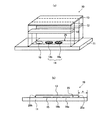
図1は、本発明の試料液分析チップの態様の一例を示す図である。図1(a)に示すように、試料液分析チップ10は、基板11と、1対のスペーサ12と、カバー13とを有する。試料液分析チップ10は、スペーサ12を介して基板11とカバー13とが貼り合わされた一体化構造をなし、基板11とカバー13との間にスペーサ12によって規定された管状の空間を備える。この空間は、試料液の流路である試料液移送路となる。図1(a)のうち符号25を付した断線部が試料液移送路となる部分である。
[Analysis chip]
FIG. 1 is a diagram showing an example of an embodiment of the sample liquid analysis chip of the present invention. As shown in FIG. 1A, the sample
基板11の表面には、試料液移送路25の内側となる領域に、第一の反応試薬領域14aと、第二の反応試薬領域14bと、検出領域15とが配置されている。また、基板11の表面には、これらの反応試薬領域などが配置されていない領域に、電極系が形成されている(図1では図示しない)。電極系とは、1対の電極(電極対)を2組以上含む電極対の集合を意味し、試料液の移送を制御するために用いられる。電極系を構成する電極対や試料液の移送を制御する方法などは後で詳細に説明する。
On the surface of the
基板11は、漏電を防止するなどの目的から、電気絶縁性の材料で形成される。電気絶縁性の材料は、特に限定されないが、例えば、ポリエチレンテレフタレート(PET)やポリカーボネート、ポリスチレン、ポリプロピレン、ポリエステルなどが挙げられる。また、基板11は、その厚さが非常に薄いフィルム状であっても、ある程度の厚みを持たせた板状であってもよい。基板11の厚さは、特に限定されるものではないが、試料液分析チップの小型化を実現し、携帯性を高めるなどの観点からは、かかる厚さが100〜1000μm程度であることが好ましい。
The
スペーサ12は、基板11上の任意の位置に対向して配置されている。この対向するスペーサ12の間隔によって、試料液移送路25の幅が規定される。スペーサ12を形成する材料は、基板11と同じ材料であってもよく、特に限定されるものではない。また、スペーサ12は、基板11とカバー13とを結合させる接着部材として作用する。そのため、スペーサ12の表面には、基板11やカバー13との接着性を向上させるための接着層があってもよい。接着層は、汎用の接着剤などによって形成された層をいう。接着剤の種類は特に限定されないが、基板11やカバー13と反応せず、かつ溶解しないものがよい。具体的には、アクリル系樹脂などが挙げられる。
The
カバー13は、スペーサ12を介して基板11と貼り合わされることにより試料液移送路25を形成する。カバー13としては、基板11と同様に漏電を防止するなどの目的から、電気絶縁性の材料で形成されたものが好適である。電気絶縁性の材料は、特に限定されないが、例えば、ポリエチレンテレフタレート(PET)やポリカーボネート、ポリスチレン、ポリプロピレン、ポリエステルなどが挙げられる。このとき、基材11やカバー13のうち、少なくとも試料液と試薬との反応変化を検出する領域(検出領域)は、光透過性の高い材料で形成されていることが好ましい。このように基材11やカバー13のうち、検出領域をなす箇所の光透過性が高いと、試料液分析チップ10において光学的に試料液の変化を容易に検出できる。なお、検出領域については、後で詳細に説明する。
The
第一の反応試薬領域14a、および第二の反応試薬領域14bは、反応試薬層が配置された領域である。反応試薬層とは、試料液中の特定成分の反応を進行させるための試薬を含む固形または半固形(ゲルなど)の層をいう。試料液中の特定成分とは、主な分析対象となる被検知物質を意味しうる。反応試薬領域は、試薬の使用数などに応じて適宜決定される。このとき、反応試薬領域は、基板11上に1つまたは2つ以上あってもよい。反応試薬領域を2つ以上形成すると、検査において複数の試薬を必要とする場合にも、試料液と試薬とを反応させるまでの間、各試薬を1箇所に混合して保存することなく、試薬を別個独立して保存することができるので、各試薬の保存安定性の高さが保たれる。また、複数の試薬と試料液とを一度に反応させるのではなく、試料液と試薬との反応を個々に行うことができるため、試料液と試薬とをムラなく均一に反応させることができ、結果として分析精度が向上する。反応試薬領域14内に反応試薬層を1つまたは2つ以上設置する場合、各反応試薬層の間隔は特に限定されず、試料液分析チップの形状や寸法に応じて適宜決定すればよい。
The first
反応試薬層に含まれる主な試薬としては、例えば、試料液中の特定成分の化学反応を触媒する酵素や、特定成分に特異的に結合する物質などが挙げられる。酵素の例には、コレステロールの酸化を触媒するコレステロールオキシダーゼや、コレステロールデヒドロゲナーゼなどが含まれる。測定対象がグルコースならグルコースオキシダーゼを、測定対象がトリグリセリド(中性脂質)なら、リポ蛋白リパーゼとグリセロールデヒドロゲナーゼを用いて反応系を構築することができる。 Examples of the main reagent contained in the reaction reagent layer include an enzyme that catalyzes a chemical reaction of a specific component in a sample solution, a substance that specifically binds to the specific component, and the like. Examples of the enzyme include cholesterol oxidase that catalyzes oxidation of cholesterol, cholesterol dehydrogenase, and the like. A reaction system can be constructed using glucose oxidase if the measurement target is glucose, and using lipoprotein lipase and glycerol dehydrogenase if the measurement target is triglyceride (neutral lipid).
特定成分に特異的に結合する物質とは、化学的あるいは物理的に結合する物質を意味する。この中には、抗原に対して特異的な結合能力を有する抗体などが含まれる。抗体には、公知のものを用いることができる。具体例としては、抗アルブミン抗体、抗HCG抗体、抗IgA抗体、抗IgM抗体、抗IgE抗体、抗IgD抗体、抗AFP抗体、抗DNT抗体、抗プロスタグランジン抗体、抗ヒト凝固ファクター抗体、抗CRP抗体、抗HBs抗体、抗ヒト成長ホルモン抗体、抗ステロイドホルモン抗体などが含まれる。また、抗体を担持した粒子を用いてもよい。抗体を担持させる粒子は任意に選択すればよく、特に限定されるものではないが、例えば、磁性金属粉、Fe3O4、γ−Fe203、Co−γ−Fe203、ナイロン、ポリアクリルアミド、などのポリマーとフェライトとの複合微粒子などが挙げられる。これらの粒子は所望とするポリマーとフェライトとをシランカップリング剤などを介して一体化させることにより形成することができるし、さらにはポリスチレンなどのポリマーの微粒子に化学結合させることによっても形成することができる。 A substance that specifically binds to a specific component means a substance that binds chemically or physically. This includes an antibody having a specific binding ability to an antigen. A well-known thing can be used for an antibody. Specific examples include anti-albumin antibodies, anti-HCG antibodies, anti-IgA antibodies, anti-IgM antibodies, anti-IgE antibodies, anti-IgD antibodies, anti-AFP antibodies, anti-DNT antibodies, anti-prostaglandin antibodies, anti-human clotting factor antibodies, anti-human coagulation factor antibodies, CRP antibodies, anti-HBs antibodies, anti-human growth hormone antibodies, antisteroid hormone antibodies and the like are included. Alternatively, particles carrying antibodies may be used. The particles for supporting the antibody may be arbitrarily selected and are not particularly limited. For example, magnetic metal powder, Fe 3 O 4 , γ-Fe 2 0 3 , Co-γ-Fe 2 0 3 , nylon And fine particles of a polymer such as polyacrylamide and ferrite and the like. These particles can be formed by integrating the desired polymer and ferrite through a silane coupling agent or the like, and can also be formed by chemically bonding to fine particles of a polymer such as polystyrene. Can do.
また、反応試薬層には、酸化還元酵素と、電子メディエータとが含まれていてもよい。酸化還元酵素とは、後述する電子メディエータに起因する電子移動を伴う酸化還元反応の触媒となる酵素である。電子メディエータとは、コレステロールやグルコースなどから電子を受け取る酸化剤として作用して還元状態となる電子伝達媒体をいう。電子メディエータの例には、フェリシアン化物イオンが含まれる。フェリシアン化物イオンは、フェリシアン化カリウムが水溶液中に溶解すると発生する。フェリシアン化物イオンは、コレステロールやグルコースなどから電子を受け取ってフェロシアン化物イオンとなる。 Further, the reaction reagent layer may contain an oxidoreductase and an electron mediator. An oxidoreductase is an enzyme that serves as a catalyst for a redox reaction involving electron transfer caused by an electron mediator described later. An electron mediator refers to an electron transfer medium that acts as an oxidizing agent that receives electrons from cholesterol, glucose, and the like, and is in a reduced state. Examples of electron mediators include ferricyanide ions. Ferricyanide ions are generated when potassium ferricyanide is dissolved in an aqueous solution. Ferricyanide ions receive electrons from cholesterol, glucose and the like and become ferrocyanide ions.
反応試薬層には、必要に応じて酵素反応を活性化させるための界面活性剤が含まれていてもよい。界面活性剤の例には、ポリオキシエチレン−p−t−オクチルフェニルエーテルやコール酸ナトリウム塩などが含まれる。ただし、界面活性剤を含む反応試薬層に接触することによって試料液移送路25の内壁面に対する試料液の濡れ性が向上する。濡れ性が高められた試料液は、試料液移送路25を下流側に自発的に移動することがある。よって、後述する試料液の移送制御方法によっても試料液の移送をうまく制御することが難しいことがある。そのため、界面活性剤を含む反応試薬層を形成する場合には、その反応試薬層を試料液移送路25内の最も下流側に配置することが好ましい。
The reaction reagent layer may contain a surfactant for activating the enzyme reaction as necessary. Examples of the surfactant include polyoxyethylene-pt-octylphenyl ether and sodium cholate. However, the wettability of the sample liquid with respect to the inner wall surface of the sample
また、反応試薬層には、タウリン、マルチトール、カルボキシメチルセルロースなどの物質が含まれていてもよい。これらの物質を含む反応試薬層は、表面形状が均一であり、かつ反応試薬層に試料液が接触した場合、反応試薬層の試薬が、試料液に迅速に溶解しうる。 Further, the reaction reagent layer may contain substances such as taurine, maltitol, carboxymethylcellulose and the like. The reaction reagent layer containing these substances has a uniform surface shape, and when the sample solution comes into contact with the reaction reagent layer, the reagent in the reaction reagent layer can be quickly dissolved in the sample solution.
検出領域15は、試薬と反応させた後の試料液に生じた変化が検出される領域である。試料液の変化には、試料液の性状が変化する試料液の物理的変化と、試料液の特定成分が化学的に別の物質に変化する化学的変化とが含まれる。ここで、性状の変化とは、色の変化、液体から固体への状態の変化などを意味する。試料液の変化は、所望の検出手段によって光学的あるいは電気的に検出される。試料液の変化を光学的に検出するとは、試料液の化学的または物理的な変化の挙動を、特定波長の電磁波に対する試料液の吸光度、透過率、または一定領域に含まれる試料液中の固形物の外観的性状により判断することである。光学的に試料液の変化を検出するための手段としては、例えば、吸光度計、画像処理装置などが挙げられる。また、光学的な検出手段には、試料液の変化を肉眼で観測することも含まれる。
The
光学的に試料液の変化を検出する場合には、検出に用いられる電磁波(目視の場合は可視光線)が検出領域15を透過する必要がある。よって、検出領域15を構成する部材は、光透過性の高い材料によって形成されたものが好ましい。光透過性の高い材料は、可視光を含む光の透過性が高い材料であり、熱可塑性樹脂でありうる。中でも、ポリエチレンテレフタレート、ポリカーボネートが好ましく、特に、ポリカーボネートは可視光に対して非常に高い光透過性を示すために有用である。
When optically detecting a change in the sample solution, the electromagnetic wave used for detection (visible light in the case of visual observation) needs to pass through the
試料液の変化を電気的に検出するとは、試料液の化学的または物理的な変化の挙動を電気的な変化によって判断することである。電気的に試料液の変化を検出する場合の検出領域15には、電極などが形成されている。検出領域15で用いられる電極系としては、測定極と対極とから構成される測定用電極対が有用である。測定用電極対、並びに測定用電極対によって試料液の変化を電気的に検出する方法は後で説明する。
The electrical detection of the change in the sample solution means that the behavior of the chemical or physical change in the sample solution is determined based on the electrical change. An electrode or the like is formed in the
また、基板11において少なくとも測定用電極が形成された領域のカバー13は、光透過性材料で形成されていることが好ましい。試料液と試薬との反応により生じた試料液の変化を目視により検出することができるからである。
Moreover, it is preferable that the
図1(b)は、一体化した試料液分析チップ10を、その中心で長手方向に切断した断面図である。図1(b)に示すように、一体化した試料液分析チップ10は、試料液供給部Aと、試料液移送路25を備えた試料液移送部Bとを含む。試料液供給部Aは、試料液移送路25の外側に位置し、後述する試料液移送路25の流入口25aを含む領域である。検査の際には、試料液供給部Aの任意の位置に試料液が滴下される。
FIG. 1B is a cross-sectional view of the integrated sample
試料液移送路25は、試料液が流れる管状の流路である。試料液移送路25の両端には、流入口25aと、空気口25bとが形成されている。流入口25aとは、試料供給部Aから試料液を導入するための開口である。一方、空気口25bは、流入口25aとは反対の終端部に形成されており、試料液移送路25内の空気を排出する。
The sample
試料液を移送するためには、試料液移送路25の壁面が、試料液、あるいは反応試薬が溶解した試料液に対して濡れ性を有することが必要である。ただし、試料液移送路25の壁面の濡れ性が高いと、試料液が自発的に移動するため、試料液の移送制御が難しい。よって、試料液移送路25は、試料液に対する濡れ性の低い材料で形成される。例えば、試料液が血液のような水溶液である場合には、試料液に対する濡れ性が比較的低いPET(ポリエチレンテレフタレート)やポリカーボネートなどのポリマーフィルムが有用である。また、試料液移送路25を構成する基板11、スペーサ12、カバー13のうち、少なくとも試料液が接触する面を、任意の材料で被覆して所望の濡れ性としてもよい。
In order to transfer the sample solution, the wall surface of the sample
試料液移送路25は、その断面形状が四角形であることが好ましい。試料液移送路25の断面の寸法は、試料液の移送を制御する上で重要な濡れ性に影響する。試料液を移送する場合には、試料液供給部Aから試料液移送路25内への試料液の自発的な流入や、試料液移送路25内で試料液を移送する際の試料液の逆流をできる限り避ける必要がある。試料液の流入や逆流などの乱流を防ぐために、試料液移送路25の断面が四角形の場合には、その断面の幅が0.5mm以上5mm以下であり、高さが5〜500μmの範囲にあることが好ましい。このように試料液移送路25の断面形状を調節すれば、試料液移送路25に対する試料液の濡れ性を好適に制御できるので、試料液移送路25内での試料液の乱流が抑えられる。
The sample
本実施形態のように反応試薬領域14と検出領域15とを分けて設置すると、反応試薬領域14から検出領域15へと試料液を移送する際に、攪拌効果により試料液が流動することから、検出領域で均一な試料液となる。
If the
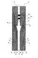
次に、試料液の移送制御に必要な電極系について説明する。電極系は、基板上に形成された1対の電極を2組以上含む。図2は、図1に示した試料液分析チップを上から見た概略図である。図2では、カバーの図示を省略し、また図1で示した部材と同じものには、同じ符号を用いている。以下において、電極系の構造を主に説明し、電極系を用いて試料液の移送を制御する方法については、後で詳細に説明する。 Next, an electrode system necessary for sample liquid transfer control will be described. The electrode system includes two or more pairs of a pair of electrodes formed on the substrate. FIG. 2 is a schematic view of the sample liquid analysis chip shown in FIG. 1 as viewed from above. 2, the illustration of the cover is omitted, and the same reference numerals are used for the same members as those shown in FIG. Hereinafter, the structure of the electrode system will be mainly described, and a method for controlling the transfer of the sample solution using the electrode system will be described in detail later.
図2に示すように、基板11上には、試料液の移送を制御するための複数の電極51〜58が形成されている。電極51,53,55,57はそれぞれ、電極52,54,56,58と、試料液移送路25を基準として対称に配置されている。対象となる電極同士で1対の電極対を構成する。また、試料液の流れに沿って隣接する電極の間には溝71〜76が切られており、各電極51〜58は互いに分離されている。溝71〜76は、試料液の移送に重要な各電極の形状を規定する。試料液の移送を適切に行うために、試料液移送路付近における各電極51〜58の、試料液移送路25の中央側の下流端部が、下流側に突出している。つまり、試料液移送路25付近における溝71〜76は、試料液の流れに対して鋭角をなすように設けられている。
As shown in FIG. 2, a plurality of
このように本実施形態の基板11上には、4組の電極対が形成されている。これらの電極対は、試料液の流れに沿って互いに隣接して配置されている。3組目以上のN組(N=3、4、5、・・・・)の電極対を配置する場合には、N組目の電極対が(N−1)組目の電極対に対して、試料液移送路25内の空気口25b側に隣接して形成されていればよい。以下の説明では、試料液の流れに沿ってもっとも上流側に配置された電極対を第一の電極対と称し、試料液の下流側に向かって配置した順に、第二、第三、第四の電極対と称する。
Thus, four electrode pairs are formed on the
第一の電極対は、電極51と電極52とから構成されている。電極51と52の一部分は、試料液移送路25の外側にある試料液供給部A上に配置されており、かつ電極51と52のうち、試料液移送路25の中央側の下流端部は、流入口25a付近まで突出した形状とされている。第二の電極対は、電極53と電極54とから構成されている。電極53と54は、第一の電極対を構成する電極51と52に対して、試料液移送路25の空気口25b側に隣接して配置されている。
The first electrode pair includes an
また、第三の電極対は、電極55と電極56とから構成されている。電極55と56は、第二の電極対を構成する電極53と54に対して、空気口25b側に隣接して配置されている。第四の電極対は、電極57と電極58とから構成されている。電極57と58は、試料液移送路25内のもっとも空気口25b側に配置されている。
The third electrode pair includes an
第一〜第四の電極対を構成する電極51〜58は、いずれも金属の薄膜であり、電極間に設けられた溝71〜76によって分離されている。また、電極51,53,55,57と電極52,54,56,58との間には非電極領域59が存在する。非電極領域59とは、各電極が配置されておらず電極として作用しない領域である。この非電極領域59の内部に、反応試薬領域14aと14bが設置されている。試料液を移送するには、移送しようとする領域に応じて、第一〜第四の電極対のいずれかに電圧をかける。通電によって電極51〜58が活性化されると、その表面での濡れ性が向上するので、試料液はエレクトロウエッティング現象により通電された電極の表面にわたって拡がる。このとき、非電極領域59に設けられた反応試薬領域14aと14bには、電圧が印加されないので、通電によって反応試薬層の特性が変化することはない。
The
図3は、流入口25a付近の拡大図である。図3に示すように、電極53〜56の一部分は、試料液移送路25内に露出している。この露出部分を「露出部」とも称する。露出部は、試料液移送路25内の試料液の流路に露出し、試料液と接触する電極の部位をいう。露出部を含む電極の対に電圧をかけると、露出部が活性化されて親水性が高まる。露出部の親水性が高まると、試料液に対する濡れ性も向上する。このとき、親水性が高められた露出部よりも上流側で静止していた試料液は、親水性が高められた露出部に引き寄せられるように移動する。図3では省略された第四の電極対も、同様の露出部を有する。
FIG. 3 is an enlarged view of the vicinity of the
試料液の移動に係る挙動は、露出部の幅x1や露出部の形状に応じる。露出部の幅x1は、試料液移送路25の幅Xに応じて適宜に設定される。露出部の幅x1とは、露出部において、試料液移送路25の壁面から試料液の流れに沿って略平行な電極を構成する一辺までの最短距離をいう。露出部の長さx1と、試料液移送路25の幅Xとの比であるx1/Xは、1/20以上1/4以下であることが好ましい。
The behavior related to the movement of the sample solution depends on the width x1 of the exposed portion and the shape of the exposed portion. The width x1 of the exposed portion is appropriately set according to the width X of the sample
例えば、x1/Xが1/4の場合には、試料液移送路25の全幅のうちの半分が、電極として機能する露出部となり、露出部を除いた残りの幅の半分が電極として機能しない領域(非電極領域)となる。これにより、反応試薬層を配置する上で十分な領域と、試料液の移送に必要な電力とを確保することができる。ただし、x1/Xが1/4を超えると、試料液移送路25の非電極領域が非常に狭くなるため、電極対に電圧をかけると、試料液移送路25内を流れる試料液が通電するおそれがある。試料液が通電されると、試料液は電気化学的に変性し、検出精度が低下する。また、試料液の移送制御が困難となり、場合によっては試料液が検出領域に混入するため、電子メディエータが溶解した反応試薬が、測定対象とは無関係に電極との相互作用で還元されてしまう。このような反応試薬の還元反応は、酵素による還元反応と区別しにくいので、測定対象物質の正確な測定が困難になる。一方、x1/Xが1/20未満の場合には、露出部が過剰に小さくなるため、試料液移送路25の壁面の濡れ性を向上させることが難しい。
For example, when x1 / X is 1/4, half of the entire width of the sample
より確実に試料液の移送を可能とし、電圧による試料液へのダメージを抑制するためには、x1/Xが1/10以上1/5以下であることがより好ましい。例えば、試料液移送路25の幅Xが1.0mmの場合には、露出部の幅x1を0.1mm〜0.2mm以下とすればよい。
In order to more reliably transfer the sample liquid and suppress damage to the sample liquid due to voltage, x1 / X is more preferably 1/10 or more and 1/5 or less. For example, when the width X of the sample
各電極対に挟まれながら電極として機能しない領域の幅x2は、試料液移送路25の幅Xとの比であるx2/Xが1/2以上9/10以下であることが好ましい。また、露出部のうち、試料液移送路25の中央部側であり、試料液を移送する方向に伸びた一辺の長さLは、少なくとも反応試薬層の直径Dより大きくする。より好ましくは、一辺の長さLを、反応試薬層の直径Dに対して2以上とする。これにより、試料液の移送に十分なエレクトロウエッティング現象を起こすことができる。
The width x2 of the region that does not function as an electrode while being sandwiched between the electrode pairs is preferably such that x2 / X, which is a ratio to the width X of the sample
露出部の形状は、試料液を、上流側から下流側へ適宜移動させることができるように設計されている。電極の露出部は、試料液移送路25の中央側の下流端部が試料液移送路25の下流側に向かって突出するように配置されている。試料液の近傍に設置された電極に電圧をかけると、試料液は、通電によって濡れ性が向上した露出部の形状に沿うように移動を開始する。よって、上記のように露出部の形状を規定すれば、通電によって活性化された露出部により試料液が上流側から下流側へ確実に誘導される。試料液の挙動は、通電された露出部によって制御され、通電されていない露出部には影響を受けない。そのため、通電された露出部と、未だ通電されていない露出部との境界付近で試料液は静止する。
The shape of the exposed portion is designed so that the sample solution can be appropriately moved from the upstream side to the downstream side. The exposed portion of the electrode is arranged so that the downstream end portion on the center side of the sample
次に、図1に示した試料液分析チップ10を用いて、本発明の試料液の移送制御方法について説明する。本発明では、試料液移送路25に試料液を移送する際に、試料液移送路中の壁面への試料液の濡れ性に起因する毛細管現象を利用する。
Next, the sample liquid transfer control method of the present invention will be described using the sample
毛管を液体中に垂直に差し込んだ場合に液体が毛管内に侵入しようとする力と、毛管上昇の高さとの間には、次式の関係が知られている(田嶋和夫 他著「界面化学」、p41、丸善、2005)。

上記式より、液体と毛管表面のなす接触角が90度以上であると、右辺はゼロまたは負となるので、毛管上昇高さhもゼロまたは負の値となる。すなわち毛管に液体が侵入できない。従って、液体と毛管表面のなす接触角が90度以下でないと毛管上昇が起こらないことが分かる。 From the above formula, if the contact angle between the liquid and the capillary surface is 90 degrees or more, the right side is zero or negative, and the capillary rising height h is also zero or negative. That is, no liquid can enter the capillary. Therefore, it can be seen that the capillary rise does not occur unless the contact angle between the liquid and the capillary surface is 90 degrees or less.
毛細管現象で試料液を移送する場合には、試料液移送路の壁面の濡れ性が重要となる。そこで本発明では、前述したように、電極対を構成する電極に露出部(試料液移送路内に露呈した部分)を設けて、試料液が接する電極の濡れ性を制御する。このとき、試料液の流れに沿って、上流側の電極対から下流側の電極対へ、順番に適切な通電操作を行うことにより、試料液を上流側から下流側へと段階的に移送する。 When transferring a sample solution by capillary action, the wettability of the wall surface of the sample solution transfer path is important. Therefore, in the present invention, as described above, an exposed portion (a portion exposed in the sample liquid transfer path) is provided on the electrodes constituting the electrode pair to control the wettability of the electrode in contact with the sample liquid. At this time, the sample solution is transferred stepwise from the upstream side to the downstream side by performing an appropriate energization operation in order from the upstream electrode pair to the downstream electrode pair along the flow of the sample solution. .
よって、本発明の試料液の移送制御方法は、(1)上述のような本発明に係る試料液分析チップを準備する工程と、(2)第一の電極対および前記第二の電極対と少なくとも部分的に重なるように試料液を滴下する工程と、(3)前記試料液を滴下された前記第一の電極対に対して、前記第二の電極対の電圧よりも大きい電圧をかける工程と、を有する。また、3組以上のN組(N=3、4、5・・・)の電極対を配置した場合には、前記試料液移送路内で前記試料液の流れに沿って隣接した任意の2組の電極対のうち、前記空気口側に配置された電極対に、前記試料液移送路内にある試料液の先端部分を接触させ、かつ静止させた状態で、前記任意の2組の電極対のうち、前記流入口側に配置された電極対に対して、前記空気口側に配置された電極対の電圧よりも高い電圧をかけることを特徴とする。この工程は、繰り返し行ってもよい。 Therefore, the sample liquid transfer control method of the present invention includes (1) a step of preparing a sample liquid analysis chip according to the present invention as described above, and (2) a first electrode pair and a second electrode pair. A step of dropping the sample solution so as to at least partially overlap; and (3) a step of applying a voltage higher than the voltage of the second electrode pair to the first electrode pair to which the sample solution has been dropped. And having. Further, when three or more sets of N pairs (N = 3, 4, 5,...) Of electrode pairs are arranged, any two adjacent along the flow of the sample solution in the sample solution transfer path. Of the pair of electrodes, the two pairs of electrodes are arranged in a state where the tip portion of the sample solution in the sample solution transfer path is in contact with the electrode pair arranged on the air port side and is stationary. A voltage higher than the voltage of the electrode pair arranged on the air port side is applied to the electrode pair arranged on the inlet side among the pair. This step may be repeated.
(1)の工程では、上述したような本発明に係る試料液分析チップを準備する。試料液分析チップを構成する部材などについては、上述と同じであるため説明を省略する。また、試料液分析チップの製造方法については後で詳細に説明する。 In the step (1), the sample liquid analysis chip according to the present invention as described above is prepared. The members constituting the sample liquid analysis chip are the same as described above, and thus the description thereof is omitted. The method for manufacturing the sample liquid analysis chip will be described in detail later.
(2)の工程では、試料液分析チップ10に試料液を導入するため、試料液を滴下する。第一の電極対および前記第二の電極対と少なくとも部分的に重なるように試料液を滴下することが好ましい。さらに好ましくは、流入口25aの手前であり、かつ流入口25aに接するように滴下する。
In the step (2), the sample liquid is dropped to introduce the sample liquid into the sample
試料液分析チップ10は、点着部を有していてもよい。点着部とは試料供給部Aにあり、試料液移送路25内への試料液の流入を容易にするように試料液が滴下される部位である。点着部には、試料液の動きを円滑にするような物質を含む層が含まれていてもよい。点着部は、流入口25aの上流側に設置することが好ましいが、その設置箇所は試料供給部Aの内部であれば特に限定されない。また、試料液を血液とする場合には、血球などの固形成分の除去が必要なことがある。この場合には、基板11上の任意の箇所に血液中の血球除去用のフィルタを設置すればよい。フィルタの設置箇所は、特に限定されるものではないが、試料液中の固形成分を除去するためには試料液移送路内に設置することが好ましい。
The sample
(3)の工程では、先ず、試料液を滴下された第一の電極対に対して、第二の電極対にかける電圧よりも高い電圧をかける。第二の電極対にかける電圧は、正の電圧とすることが好ましい。このとき、試料液は、通電によって活性化された第一の電極対に沿って、試料液供給部Aから試料液移送路25内へ誘導される。さらに、試料液移送路25内で試料液は、活性化された第二の電極対の露出部に沿って下流側へと移動する。その移動により試料液は、第二の電極対に挟まれた第一の反応試薬領域14aに接触し、その試薬が試料液に徐々に溶解する。これにより、第一の反応試薬領域14aに保持されていた酵素などの試薬と試料液とが反応する。試料液移送路25内に誘導された試料液は、第二の電極対の下流側に隣接し、未だ通電されていない不活性な第三の電極対に接触して静止する。
In the step (3), first, a voltage higher than the voltage applied to the second electrode pair is applied to the first electrode pair to which the sample solution has been dropped. The voltage applied to the second electrode pair is preferably a positive voltage. At this time, the sample solution is guided from the sample solution supply unit A into the sample
第一の反応試薬領域14aに保持されていた試薬と試料液との反応が完了した後に、第二の電極対に対して、第三の電極対の電圧よりも高い電圧をかける。先ほどと同様に、試料液は、活性化されて濡れ性が向上した第三の電極対の露出部を覆うように拡がり始め、第三の電極対よりも下流側へ移送される。試料液の移動は、第三の電極対と第四の電極対との境界部まで進行するが、未だ通電されていない不活性な第四の電極対に接触して静止する。
After the reaction between the reagent held in the first
このとき、試料液は、第三の電極対に挟まれた第二の反応試薬層14b内へと誘導され、第二の反応試薬領域14bに保管されていた試薬が試料液に徐々に溶解する。第二の反応試薬領域14bに到達した試料液には、既に第一の反応試薬領域14aの試薬が溶解しているため、新たな試薬と試料液との反応が好適に行われる。このように本発明では、複数の反応を過不足なく段階的に進め、試薬が均一に溶解した試料液を、新たな反応試薬層へと移送することができる。また、試料液移送路25の寸法を所定の範囲内で好適に調節することにより、試料液の乱流を抑えることができるので、試料液を反応試薬層へと確実に移送できる。
At this time, the sample solution is guided into the second
第二の反応試薬領域14bにおいて試料液と試薬との反応が完了した後に、第三の電極対に対して第四の電極対の電圧よりも高い電圧をかける。これに伴い、試料液は更に、試料液移送路25内の空気口25b側に誘導される。第四の電極対は、空気口25bの近傍まで伸びているので、試料液は空気口25b部分まで誘導されて静止する。なお、基板11表面の第四の電極対で挟まれた領域は、金属薄膜の被覆が無く、透明な絶縁性の基板11が露出している。ここで、カバー13は、光透過性の高い材料で形成されているため、第四の電極対で挟まれた領域を検出領域として、光学的に試料液の変化を検出することが可能である。この試料液の変化は、第一の反応試薬領域14aと第二の反応試薬領域14bとの成分が試料液に溶解し、所定の化学反応が生じた変化を含む。
After the reaction between the sample solution and the reagent is completed in the second
また、電極対に直流の電圧をかける場合には、より低電位側の電極対の方が電極面への液滴の濡れ性向上の効果が大きい。そこで、隣接する電極対の間に電圧をかける場合には、空気口側24側の電極対が正になるように電圧をかけることが好ましい。 Further, when a direct voltage is applied to the electrode pair, the electrode pair on the lower potential side has a greater effect of improving the wettability of the droplets on the electrode surface. Therefore, when a voltage is applied between adjacent electrode pairs, it is preferable to apply a voltage so that the electrode pair on the air port side 24 becomes positive.
以上のように、本発明では、試料液の流れに沿って隣接して複数の電極対を配置し、その中から任意に選択した2組の電極対に対して電圧をかける。任意の2組の電極対は、試料液の先端部分と近接している流入口側の電極対A、および空気口25b側の電極対Bを選べばよい。ここで、試料液を移送させる方向に対して上流側の電極対Aの電圧は、電極対Bにかける電圧よりも高い正の電圧とすることが好ましく、より好ましくは、電極対Aにかける電圧を、電極対Bにかける電圧よりも+2〜3V高くする。これにより、通電によって活性化された電極対A、Bの濡れ性が向上し、試料液は電極対Bの表面を覆うように拡がり始め、空気口側へと徐々に移送される。ここで、電極対Aにかける電圧を電極対Bにかける電圧よりも低くすると、試料液の移送は可能であるが、本発明のように電極対Aにかける電圧を電極対Bにかける電圧よりも高くした場合と比べて明らかに移送速度が遅くなる。
As described above, in the present invention, a plurality of electrode pairs are arranged adjacent to each other along the flow of the sample solution, and voltage is applied to two pairs of electrode pairs arbitrarily selected from them. Any two pairs of electrodes may be selected from the electrode pair A on the inlet side and the electrode pair B on the
この後、試料液は電極対Bの表面にわたって下流側へ移動し、電極対Bの下流外側近傍で静止する。その理由は、通電されていない電極対Bの下流外側は不活性であり、試料液の移送に必要な濡れ性が高くないからである。例えば、電極対Bの下流側に、通電されていない電極対Cが隣接している場合には、試料液は、電極対Bと電極対Cとの境界部付近で静止する。このように、2組の電極対に対して好適に電圧を印加/停止する操作を繰り返せば、移送/停止を含む試料液の移送制御が実現でき、試料液を目的地まで確実に移送できる。 Thereafter, the sample liquid moves downstream over the surface of the electrode pair B and stops at the vicinity of the downstream outer side of the electrode pair B. This is because the downstream outer side of the electrode pair B that is not energized is inactive, and the wettability necessary for transferring the sample liquid is not high. For example, when the electrode pair C that is not energized is adjacent to the downstream side of the electrode pair B, the sample solution is stopped near the boundary between the electrode pair B and the electrode pair C. As described above, by repeating the operation of suitably applying / stopping the voltage to the two pairs of electrodes, the sample liquid transfer control including transfer / stop can be realized, and the sample liquid can be reliably transferred to the destination.
また、本発明では、3組以上のN組(N=3、4、5・・・)の電極対を配置した試料液分析チップにおいても、試料液を目的地まで確実に移送できる。この場合、先ず、第一の電極対および第二の電極対と少なくとも部分的に重なるように試料液を滴下してから、第一の電極対に対して、第二の電極対の電圧よりも大きい電圧をかけることにより、活性化された第二の電極対にわたって拡がるように試料液を移送し、試料液移送路内に試料液を流入させる。次に、試料液移送路内で流入口側から空気口側まで隣接した任意の3組の電極対を選択する。任意の3組の電極対は、試料液の先端部分が接触している電極対Dを中央とし、その両隣に配置された2組の電極対E、Fを選択すればよい。選択した3組の電極対のうち、試料液移送路のもっとも流入口側に配置された電極対Eに対して、電極対Eと空気口側で隣接した電極対Dの電圧よりも高い電圧をかける。電圧の大きさは、2組の電極対を用いる場合と同じように、電極対Dの電圧を、電極対Eの電圧よりも+2〜3V高くすることが好ましい。このとき、3組の電極対のうちでもっとも空気口側に配置された電極対Fは通電せず(すなわち、電圧=0)、不活性状態とする。すると、電極対Dに接触し、かつ静止していた試料液は、通電によって活性化された電極対Dの表面を拡がるように移動し始め、電極対Dと不活性な電極対Fとの境界部で静止する。このように、3組の電極対を適宜選択し、2組の電極対を活性化すると同時に、この2組の電極対のうち空気口側に配置された電極対と空気口側で隣接した1組の電極対を不活性化すれば、試料液の移送/停止を制御しながら、試料液を確実に目的地まで移送できる。なお、試料液を移送/停止する操作は、目的地まで繰り返し行えばよい。 In the present invention, the sample solution can be reliably transferred to the destination even in the sample solution analysis chip in which three or more sets of N pairs (N = 3, 4, 5,...) Are arranged. In this case, first, after dropping the sample solution so as to at least partially overlap the first electrode pair and the second electrode pair, the voltage of the second electrode pair is more than the voltage of the second electrode pair. By applying a large voltage, the sample solution is transferred so as to spread over the activated second electrode pair, and the sample solution is caused to flow into the sample solution transfer path. Next, arbitrary three electrode pairs adjacent from the inlet side to the air outlet side in the sample liquid transfer path are selected. The arbitrary three electrode pairs may be selected from the two electrode pairs E and F arranged on both sides of the electrode pair D that is in contact with the tip of the sample solution. Of the three selected electrode pairs, a voltage higher than the voltage of the electrode pair D adjacent to the electrode pair E on the air inlet side is applied to the electrode pair E arranged on the most inlet side of the sample liquid transfer path. Call. As in the case of using two electrode pairs, it is preferable that the voltage of the electrode pair D be +2 to 3 V higher than the voltage of the electrode pair E. At this time, among the three electrode pairs, the electrode pair F arranged closest to the air opening is not energized (that is, voltage = 0) and is in an inactive state. Then, the sample liquid that is in contact with the electrode pair D and is stationary starts to move so as to expand the surface of the electrode pair D activated by energization, and the boundary between the electrode pair D and the inactive electrode pair F. It stops at the part. In this way, three electrode pairs are selected as appropriate, and the two electrode pairs are activated, and at the same time, the electrode pair arranged on the air port side of the two electrode pairs is adjacent to the air port side. By inactivating the pair of electrodes, the sample liquid can be reliably transferred to the destination while controlling the transfer / stop of the sample liquid. The operation of transferring / stopping the sample solution may be repeated up to the destination.
試料液を目的地までより確実に移送するためには、感知領域を備えた試料液分析チップを用いればよい。感知領域は、移送する試料液の位置を、感知手段によって電気的または光学的に感知する領域であり、基板上の任意の位置に設置される。また、感知領域は、検出領域と同様に光透過性の高い材料で形成された部材で構成されていてもよい。感知手段については、特に限定されず、前述した検出手段と同じものであってもよいし、試料液移送用の電極対であってもよい。より確実に試料液を目的地まで移送するためには、試料液を移送させる目的地の上流側近傍に設置することが好ましい。好ましい設置箇所には、試料液の移送に用いる隣接した、電圧を印加される2組の電極対のうち、空気口側に配置された電極対と、この電極対よりもさらに空気口側に隣接した、電圧を印加されない不活性な電極対との境界部が含まれる。 In order to more reliably transfer the sample liquid to the destination, a sample liquid analysis chip having a sensing area may be used. The sensing area is an area where the position of the sample liquid to be transferred is sensed electrically or optically by the sensing means, and is set at an arbitrary position on the substrate. In addition, the sensing area may be configured by a member formed of a material having high light transmittance, like the detection area. The sensing means is not particularly limited, and may be the same as the detection means described above, or may be an electrode pair for transferring a sample liquid. In order to transfer the sample solution to the destination more reliably, it is preferable to install the sample solution in the vicinity of the upstream side of the destination to which the sample solution is transferred. Among the two electrode pairs that are adjacent to each other used for transferring the sample liquid and to which a voltage is applied, a preferred installation location is an electrode pair disposed on the air port side and further adjacent to the air port side than this electrode pair. In addition, a boundary portion with an inactive electrode pair to which no voltage is applied is included.
試料液の位置を電気的に感知する場合には、(a)電気的に変化を感知する感知領域を備えた試料液分析チップを準備する工程、(b)第一の電極対および第二の電極対と少なくとも部分的に重なるように試料液を滴下する工程、(c)試料液が部分的に重なった第一の電極対に対して、第二の電極対の電圧よりも大きい電圧をかける工程、さらに(d)感知領域において1の電極対に試料液が接触したことを電気的な変化として感知する工程、を順次行う移送制御方法を用いればよい。さらに、3組以上のN組(N=3、4、5・・・)の電極対を配置する場合には、試料液移送路内において、試料液の流れに沿って隣接した任意の2組の電極対のうち、空気口側に配置された電極対Bに、試料液移送路内にある試料液の先端部分が接触したことを感知領域によって感知した後、試料液を、電極対Bに接触させ、かつ静止させた状態で、電極対Aに対して、電極対Bの電圧よりも高い電圧をかける工程を繰り返し行う。上述した「電気的な変化」は、試料液の移送を制御するために電圧を印加された2組の電極対の間の抵抗値の減少として感知される。例えば、試料液が電極対Bの端部に接触すると、電極対Aと電極対Bとの間の抵抗値が減少する。この抵抗値の減少により、試料液の先端部分が電極対Bまで移送されたと判断される。 When the position of the sample liquid is electrically sensed, (a) a step of preparing a sample liquid analysis chip having a sensing region for electrically sensing a change, (b) a first electrode pair and a second electrode (C) applying a voltage higher than the voltage of the second electrode pair to the first electrode pair partially overlapping the sample liquid; What is necessary is just to use the transfer control method which performs a process and the process of further detecting (d) an electrical change that the sample liquid contacted one electrode pair in the sensing area. Furthermore, in the case where three or more N pairs (N = 3, 4, 5,...) Of electrode pairs are arranged, any two pairs adjacent to each other along the flow of the sample liquid in the sample liquid transfer path. After detecting that the tip portion of the sample liquid in the sample liquid transfer path is in contact with the electrode pair B arranged on the air opening side of the electrode pair of the electrode pair, the sample liquid is applied to the electrode pair B. The step of applying a voltage higher than the voltage of the electrode pair B to the electrode pair A is repeatedly performed in a state of contact and stationary. The above-mentioned “electrical change” is sensed as a decrease in the resistance value between two pairs of electrodes to which a voltage is applied in order to control the transfer of the sample liquid. For example, when the sample solution contacts the end of the electrode pair B, the resistance value between the electrode pair A and the electrode pair B decreases. It is determined that the tip portion of the sample liquid has been transferred to the electrode pair B due to the decrease in the resistance value.
試料液の位置を光学的に感知する場合には、(f)光学的に変化を感知する感知領域を備えた試料液分析チップを準備する工程、(g)第一の電極対および第二の電極対と少なくとも部分的に重なるように試料液を滴下する工程、(h)試料液が部分的に重なった第一の電極対に対して、第二の電極対の電圧よりも大きい電圧をかける工程、さらに(i)感知領域において1の電極対に試料液が接触したことを光学的な変化として感知する工程、を順次行う移送制御方法を用いればよい。さらに、3組以上のN組(N=3、4、5・・・)の電極対を配置する場合には、試料液移送路内において、試料液の流れに沿って隣接した任意の2組の電極対のうち、空気口側に配置された電極対Bに、試料液移送路内にある試料液の先端部分が接触したことを感知領域によって感知した後、試料液を、空気口側の電極対Aに接触させ、かつ静止させた状態で、電極対Aに対して、電極対Bの電圧よりも高い電圧をかける工程を繰り返し行えばよい。このとき、感知領域において、目視などを含めた感知手段によって試料液の先端部分の位置を確認し、試料液が所望とする位置まで移送できたことを確認しながら適宜試料液の移送/停止に係る操作を行うと、より確実に試料液を順次目的地まで移送できる。 When optically sensing the position of the sample liquid, (f) preparing a sample liquid analysis chip having a sensing region for optically sensing a change, (g) a first electrode pair and a second electrode Dropping the sample solution so as to at least partially overlap the electrode pair; (h) applying a voltage higher than the voltage of the second electrode pair to the first electrode pair partially overlapping the sample solution; A transfer control method for sequentially performing the steps and (i) the step of sensing as an optical change that the sample liquid has contacted one electrode pair in the sensing region may be used. Furthermore, in the case where three or more N pairs (N = 3, 4, 5,...) Of electrode pairs are arranged, any two pairs adjacent to each other along the flow of the sample liquid in the sample liquid transfer path. After detecting that the tip portion of the sample liquid in the sample liquid transfer path is in contact with the electrode pair B arranged on the air mouth side among the electrode pairs of The step of applying a voltage higher than the voltage of the electrode pair B to the electrode pair A in a state where the electrode pair A is in contact with and stationary may be repeated. At this time, in the sensing area, the position of the tip of the sample liquid is confirmed by sensing means including visual observation, and the sample liquid is appropriately transferred / stopped while confirming that the sample liquid has been transferred to the desired position. When such an operation is performed, the sample liquid can be sequentially transferred to the destination more reliably.
また、試料液の位置を感知する第一の感知領域とは別に、反応試薬層の変化を感知する第二の感知領域を設けることもできる。反応試薬層の変化とは、反応試薬層が試料液に溶解あるいは反応することを意味する。第二の感知領域は、反応試薬層が配置された部位と同じか、もしくはその部位の近傍に設置すればよい。反応試薬層で起こる試料液と試薬との反応挙動をより確実に観察するためには、第二の感知領域を、反応試薬層の近傍であって、試料液の流れに対し下流側に設置することが好ましい。第二の感知領域に用いられる感知手段は、上述した第一の感知手段と同じものを用いればよく、その中には目視による観察も含まれる。 In addition to the first sensing region for sensing the position of the sample solution, a second sensing region for sensing a change in the reaction reagent layer can be provided. The change of the reaction reagent layer means that the reaction reagent layer is dissolved or reacted in the sample solution. The second sensing region may be installed at the same location as the site where the reaction reagent layer is disposed or in the vicinity thereof. In order to more reliably observe the reaction behavior between the sample solution and the reagent that occurs in the reaction reagent layer, the second sensing region is located near the reaction reagent layer and downstream of the sample solution flow. It is preferable. The sensing means used in the second sensing area may be the same as the first sensing means described above, and includes visual observation.
[試料液分析チップを用いた分析方法]
次に、本発明に係る試料液分析チップを用いた分析方法について説明する。以下の説明では、図1および図2で示した試料液分析チップ10を用いて、血漿中のコレステロール濃度を測定する形態について説明する。ただし、本発明の試料液分析チップは、血中のコレステロールを測定する方法に限らず、他の測定にも同様に用いることができる。
[Analysis method using sample solution analysis chip]
Next, an analysis method using the sample liquid analysis chip according to the present invention will be described. In the following description, a mode in which the cholesterol concentration in plasma is measured using the sample
診断指針として用いられる血清コレステロール値は、コレステロールとコレステロールエステルの濃度を合計したものである。コレステロールの測定は、酵素(コレステロールオキシダーゼ:ChOD)を用いて、コレステロールを酸化する測定方法が一般的である。しかし、コレステロールエステルはChODによる酸化反応の基質になることができないので、コレステロールエステルをコレステロールに変化させるコレステロールエステラーゼ(ChE)を用いる方法が知られている。すなわち血清コレステロール濃度は、二種の酵素を用いて、以下の反応Aおよび反応Bを利用して測定される。
反応A:コレステロールエステル→コレステロール+脂肪酸(酵素ChEによる反応)
反応B:コレステロール+フェリシアン化イオン→コレステノン+フェロシアン化イオン(酵素ChODによる反応)
The serum cholesterol value used as a diagnostic guide is the sum of the concentrations of cholesterol and cholesterol ester. As for the measurement of cholesterol, a measuring method for oxidizing cholesterol using an enzyme (cholesterol oxidase: ChOD) is generally used. However, since cholesterol ester cannot be a substrate for the oxidation reaction by ChOD, a method using cholesterol esterase (ChE) that converts cholesterol ester to cholesterol is known. That is, the serum cholesterol concentration is measured using the following reactions A and B using two kinds of enzymes.
Reaction A: Cholesterol ester → cholesterol + fatty acid (reaction with enzyme ChE)
Reaction B: Cholesterol + ferricyanide ion → cholestenone + ferrocyanide ion (reaction with enzyme ChOD)
本測定では、第一の反応試薬領域14aに、フェリシアン化イオンを主成分とする反応試薬層、第二の反応試薬領域14bにChE、およびChODを主成分とする反応試薬層を配置する。このとき、例えば、仮に、ChE、およびChODの両方を含有する反応試薬層を、上流側に配置された第一の反応試薬領域に配置すれば、血液と、ChE、およびChODによる反応Bが生じる。反応Bは、フェリシアン化物イオンがない状態でも、血液中に酸素があれば進行するためである。反応Bが開始すると、酸素が還元されて過酸化水素が生成するので、その後に第二の反応試薬領域14bのフェリシアン化イオンと血液とを反応させても、フェリシアン化イオンを定量してコレステロールの濃度を正確に測定できない。
In this measurement, a reaction reagent layer mainly composed of ferricyanide ions is arranged in the first
まず、試料液である血液を、試料供給部A内であり、試料液移送路25の流入口25a付近の点着部に滴下する。血液を滴下する際には、電極51と52から構成される第一の電極対と、第一の電極対よりも空気口25b側に配置された第二の電極対とのいずれにも接するように試料液を滴下する。
First, blood, which is a sample solution, is dropped in the spotting portion in the sample supply unit A and near the
第一の電極対に対して、第二の電極対の電圧よりも+2〜3V程度高い電圧をかける。これにより、血液は、第二の電極対の露出部を覆うように拡がり、試料液移送路25内に流入する。試料液移送路25内に流入した血液は、第二の電極対と第三の電極対との境界部で静止する。血液は、第二の電極対に挟まれた第一の反応試薬領域14aに接触する。このとき、第一の反応試薬層が血液に溶解し、血液とフェリシアン化カリウムとが混合する。ただし、フェリシアン化イオンは、それ単独ではコレステロールまたはコレステロールエステルと反応することができないので、第一の反応試薬領域14aでは単に試薬同士が混合される。
A voltage higher by about +2 to 3 V than the voltage of the second electrode pair is applied to the first electrode pair. Thereby, the blood spreads so as to cover the exposed portion of the second electrode pair and flows into the sample
第一の反応試薬領域14aにおいて、血液と試薬との混合が十分になされた後、第二の電極対に対して、電極55と56で構成された第三の電極対の電圧よりも+2〜3V程度高い電圧をかける。第三の電極対は、第二の電極対よりも空気口25b側に隣接する電極対であるから、第一の電極対と第二の電極対との境界部で静止した血液は、第三の電極対の露出部を覆うように拡がり始め、結果的に第三の電極対に挟まれた第二の反応試薬領域14bまで誘導される。第二の反応試薬領域14bでは、第二の反応試薬層に血液が溶解する。ここで、既に第一の反応試薬領域14aの成分が溶け込んだ血液に、第二の反応試薬層14bの成分が混合され、新たな反応が起こる。
In the first
本測定の第二の反応試薬領域14bは、ChE、およびChODを主成分とするため、血液中のコレステロールエステルがChEによりコレステロールに変化する。この血液は、変化したコレステロールと、元来血液に含まれていたコレステロールとが共存した状態にある。ここで、各コレステロールは、ChODによりコレステノンに酸化される。また、血液中のフェリシアン化カリウムが、フェロシアン化カリウムに還元される。
Since the second
第二の反応試薬層には、血液の濡れ性を高めないようにするため、界面活性剤を含有させない場合がある。界面活性剤がないと、ChEによってコレステロールエステルがコレステロールへと変化する反応速度は比較的緩やかとなる。よって、ChEの濃度やその比活性にもよるが、第二の反応試薬層での反応時間は少なくとも10分程度を必要とする。 The second reaction reagent layer may not contain a surfactant so as not to increase the wettability of blood. In the absence of a surfactant, the rate of reaction of converting cholesterol ester to cholesterol by ChE is relatively slow. Therefore, although it depends on the concentration of ChE and its specific activity, the reaction time in the second reaction reagent layer requires at least about 10 minutes.
第二の反応試薬領域14bでの反応が完了した後に、第三の電極対に対して、電極57と58で構成された第四の電極対の電圧よりも+2〜3V程度高い電圧をかける。第二の電極対と第三の電極対との境界部で静止していた血液は、第四の電極対の露出部を覆うように拡がり、結果としてより空気口25b側に移動する。第四の電極対は、空気口25bまで伸びるように形成されているので、血液は空気口25bに到達して静止する。
After the reaction in the second
血液は、基板11上の第四の電極対に挟まれている検出領域15に誘導される。検出領域15は、電極を形成するための金属薄膜によって覆われておらず、光透過性の高い電気絶縁性を有する基板11が露出している。また、カバー13は、光透過性の高い材料で形成されている。よって、例えば、目視により反応後の血液の色を観察して、予め作成しておいた反応前の血液の色の見本と比較すれば、血液と試薬との反応の程度を確認することができる。またフェリシアン化カリウムの減少量を吸光度によって測定すれば、フェロシアン化カリウムの定量が可能であり、血中コレステロール濃度が定量できる。また、フェリシアン化イオンの減少量は、酸化反応により減少するコレステロールの量に対応する。そのため、フェリシアン化イオンの減少量を検出領域15で定量すれば、コレステロール濃度を算出することも可能である。
The blood is guided to the
複数の試薬を含有する反応試薬層を一箇所に配置すれば、保存期間の長さにつれて試薬の劣化が起こるため保存安定性に欠ける。一方、上記のように複数の試薬をそれぞれ別の領域に配置すれば、試薬の保存安定性が格段に向上する。また、各試薬をそれぞれ別の領域に配置すれば、反応の順序も適宜制御することができるので、より分析精度の高い測定が可能となる。さらに、複数の反応試薬領域を任意の間隔をもたせて配置すれば、保存される試薬同士が混ざり合うことがないので、分析精度はよりいっそう向上する。 If a reaction reagent layer containing a plurality of reagents is arranged in one place, the reagent deteriorates with the length of the storage period, so that the storage stability is lacking. On the other hand, if a plurality of reagents are arranged in different regions as described above, the storage stability of the reagents is remarkably improved. In addition, if the reagents are arranged in different regions, the order of the reactions can be controlled as appropriate, so that measurement with higher analysis accuracy is possible. Furthermore, if a plurality of reaction reagent regions are arranged with an arbitrary interval, the stored reagents will not be mixed with each other, so that the analysis accuracy is further improved.
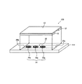
次に、電極を用いて電気的に試料液の変化を検出する方法について説明する。電極を用いて電気的に試料液の変化を検出する場合には、図4に示すような試料液分析チップ100を用いればよい。試料液分析チップ100は、測定用電極対を追加した基板を用いた以外は、図1で示した試料液分析チップと同じである。そのため、試料液分析チップ10で説明した部材と同じものには同符号を付し、説明は省略する。また、光透過性を有するカバー13の図示は省略する。以下の説明では、試料液である血漿中のコレステロール濃度を測定する形態を例示する。
Next, a method for electrically detecting a change in the sample solution using the electrode will be described. When the change of the sample solution is electrically detected using the electrode, a sample
試料液分析チップ100を構成する基板111上には、第一の反応試薬領域14aと第二の反応試薬領域14bのほかに、第三の反応試薬領域14cが形成されている。第三の反応試薬領域14cは、試料液移送路25内のもっとも空気口25b側であり、後述する測定用電極対60(図5参照)の表面を覆うようにして配置される。
On the
試料液を血漿とする場合、第一の反応試薬領域14a、および第二の反応試薬領域14bには、いずれもフェリシアン化カリウムを主成分とした反応試薬層を配置することが好ましい。また、第三の反応試薬領域14cには、ChE、およびChODを主成分とする反応試薬層を配置することが好ましい。試料液移送路25のもっとも下流に位置する第三の反応試薬領域14cの反応試薬層には、ChEの触媒活性を向上させるための界面活性剤、例えば、TritonX−100、コール酸ナトリウム、オクチル−β−d−チオグルコシドなどを含ませてもよい。界面活性剤が血漿に混入すれば、試料液移送路25の内壁に対する血漿の濡れ性が向上するため、血漿の移送を制御することが難しくなるが、一方、測定用電極対を覆う第三の反応試薬領域14cに界面活性剤を含ませることで、反応に必要な試薬が測定用電極対の近傍から流出することを極力抑えることができる。
When the sample solution is plasma, it is preferable to dispose a reaction reagent layer mainly composed of potassium ferricyanide in the first
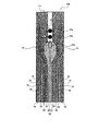
図5に示すように、試料液分析チップ100を構成する基板111上には、血漿の移送を制御するための第一〜第四の電極対のほかに、測定用電極対60が形成されている。測定用電極対60は、1対の電極である測定極61と対極62とから構成されており、試料液移送路25の内壁の一部、好ましくは底面に配置されている。測定極61と対極62とによって試料液中の物質、または試料液中の物質と反応試薬との化学反応によって生成した物質の酸化反応、あるいは還元反応による電流値を測定することにより、試料液中の特定の物質の濃度が検出できる。また、測定極61と隣接した電極58との間、および対極62と隣接した電極57との間には、それぞれ溝77および78が設けられている。
As shown in FIG. 5, a
測定用電極対60を構成する測定極61、および対極62は、いずれも導体または半導体からなる平面電極である。測定極61は、検出領域15の中央部に配置されている。この測定極61の近傍には、測定極61を取り囲むようにして対極62が配置されている。測定局61、および対極62は、個々に独立させた電極として形成してもよいし、1つの導体あるいは半導体を2つに分割したものでもよい。また、本実施形態では測定用電極対を1つ設置した形態を示したが、測定用電極対の設置数は特に限定されず、1つまたは2つ以上を設置すればよい。
The measurement electrode 61 and the counter electrode 62 constituting the
測定極61の幅は、試料液移送用の電極対と試料液移送路25の幅との関係で規定される。試料液の変化を検出するという測定極61としての機能を十全に発揮させるためには、測定極61の幅が0.1mm以上1.0mm以下であることが好ましく、より好ましくは0.2mm以上0.6mm以下である。また、試料液移送用の電極対と測定用電極対とは、導線(リード線)を介して外部の端子と接続されていることが好ましい。これにより、外部に設置した電気化学測定装置などと容易に接続できる。導線の材料には、一般的に知られている導体を用いることができるが、中でも、金、白金、銀、銅、パラジウムなどが好適に用いられる。
The width of the measurement electrode 61 is defined by the relationship between the electrode pair for sample liquid transfer and the width of the sample
前述した試料液の移送制御方法にしたがって、試料液供給部Aに滴下した血漿を試料液移送路25内の第三の反応試薬領域14cまで誘導する。第三の反応試薬領域14cの表面まで血漿を誘導した後、測定用電極対60にパルス電圧をかける。このとき、フェロシアン化カリウムがフェリシアン化カリウムになる酸化反応による電流値が測定される。その測定された電流値から血漿中のフェロシアン化カリウムの濃度を定量することによって、血中コレステロール濃度を定量することができる。
In accordance with the sample liquid transfer control method described above, the plasma dropped onto the sample liquid supply unit A is guided to the third
[本発明の試料液分析チップの製造方法]
本発明の試料液分析チップは、発明の効果を損なわない限り任意の方法で製造できるが、以下好ましい製造方法について説明する。
[Method for Producing Sample Solution Analysis Chip of the Present Invention]
The sample liquid analysis chip of the present invention can be produced by any method as long as the effects of the invention are not impaired. Hereinafter, a preferred production method will be described.
本発明の試料液分析チップは、(A)基板に相当する絶縁性のフィルム状基板上に試料液移送用の電極対、および必要に応じて、電気的あるいは化学的に試料液の変化を検出するための測定用電極対を形成する工程と、(B)基板上に反応試薬層を形成する工程と、(C)基板とカバーとを、基板の両端部に配置した1対のスペーサを介して貼り合わせることにより、両端が解放された試料液移送路を形成する工程と、を経て製造できる。各工程を実施する順番は特に限定されないが、作業性の面から、最後に(C)工程を実施することが好ましい。 The sample liquid analysis chip of the present invention (A) detects an electrode pair for transferring a sample liquid on an insulating film-like substrate corresponding to the substrate and electrically or chemically changes the sample liquid as required. A step of forming a measurement electrode pair, (B) a step of forming a reaction reagent layer on the substrate, and (C) a pair of spacers arranged on both ends of the substrate, with the substrate and the cover interposed therebetween. And bonding them together to form a sample liquid transfer path with both ends released. Although the order in which each step is performed is not particularly limited, it is preferable that step (C) is finally performed from the viewpoint of workability.
(A)の工程においては、電気絶縁性の基板の上に試料液を移送するための複数の電極対、および必要に応じて測定用電極対を形成する。 In the step (A), a plurality of electrode pairs for transferring the sample liquid and, if necessary, electrode pairs for measurement are formed on an electrically insulating substrate.
電極対を形成する方法としては、例えば、基板の表面にスパッタまたは蒸着によって金属薄膜を形成した後、金属薄膜の一部を除去することによって各電極間に断線部を形成する方法が挙げられる。金属薄膜の一部を除去する方法は、ヤスリ状のバイトを装着したリューターで物理的に掻きとる方法や、金属薄膜に吸収される波長のレーザーを照射し、照射部分の金属薄膜を飛散させる方法を用いることが可能である。中でも、YAGレーザーは、PETには吸収されず、金、パラジウムなどの貴金属には吸収されるので有用である。上記のように電極を形成すれば、基板を露出させて形成される絶縁状態の断線部は、線状に形成することができるので、この線幅によって電極間のギャップとして採れる最短距離を得ることが可能となる。よって、複数の電極対を形成する場合には、非常に有効な方法である。 As a method of forming the electrode pair, for example, a method of forming a disconnection portion between each electrode by forming a metal thin film on the surface of the substrate by sputtering or vapor deposition and then removing a part of the metal thin film. A method of removing a part of the metal thin film is a method of physically scraping with a ruter equipped with a file-shaped tool, or a method of irradiating a laser having a wavelength absorbed by the metal thin film to scatter the metal thin film in the irradiated portion. Can be used. Among them, the YAG laser is useful because it is not absorbed by PET but is absorbed by noble metals such as gold and palladium. If the electrodes are formed as described above, the disconnection portion in the insulating state formed by exposing the substrate can be formed in a linear shape, and therefore, by this line width, the shortest distance that can be taken as a gap between the electrodes is obtained. Is possible. Therefore, it is a very effective method when forming a plurality of electrode pairs.
電極対を形成する他の方法として、スパッタや蒸着によって所望のパターンの金属薄膜を基板表面に形成する方法がある。この方法は、前述の方法とは異なり、電極対を構成する電極の平面形状に相当する部分以外をマスク板によって覆った状態で、基板に金属薄膜を形成する。この方法を用いると、基板上の任意の位置に電極を形成し、かつ金属薄膜で被覆されない領域を精度良く形成することが可能である。例えば、透明なPET製の基板に電極対を構成し、かつ、検出領域には金属薄膜を形成しないようにすれば、検出領域で光学的に試料液の変化を検出する試料液分析チップを容易に得ることが可能である。 As another method of forming the electrode pair, there is a method of forming a metal thin film having a desired pattern on the substrate surface by sputtering or vapor deposition. Unlike the above-described method, this method forms a metal thin film on a substrate in a state where portions other than the portion corresponding to the planar shape of the electrodes constituting the electrode pair are covered with a mask plate. When this method is used, it is possible to form an electrode at an arbitrary position on the substrate and to accurately form a region not covered with the metal thin film. For example, if an electrode pair is formed on a transparent PET substrate and a metal thin film is not formed in the detection area, a sample liquid analysis chip that optically detects changes in the sample liquid in the detection area can be easily obtained. It is possible to get to.
さらに、電極対を形成する別の方法として、金属粒子を混ぜ込んだペーストをスクリーン印刷によって基板に塗布する方法もある。この方法は、スパッタや蒸着の装置が無くても実施可能な、比較的間便な方法である。しかし、電極形状の寸法精度は前述した2法より若干劣る場合が多いので、精密、あるいは微小な電極形状の形成には適さないことがある。 Furthermore, as another method for forming the electrode pair, there is a method in which a paste mixed with metal particles is applied to a substrate by screen printing. This method is a relatively convenient method that can be performed without a sputtering or vapor deposition apparatus. However, since the dimensional accuracy of the electrode shape is often slightly inferior to the two methods described above, it may not be suitable for forming a precise or fine electrode shape.
平面電極である測定用電極対を形成する場合には、導体を含むペーストの印刷により形成するか、スパッタ法、蒸着法などの公知の方法を用いて形成することができる。また、平面電極は、ポリエチレンテレフタレートなどの基板表面に、金、白金、銀、銅、パラジウム、クロム、カーボンなどを薄膜状に蒸着して形成してもよい。導体の材料は、試料液中で電気化学的に反応してイオン化したり、酸化作用や還元作用を受けたりするものでないことが好ましい。 When forming a measurement electrode pair which is a planar electrode, it can be formed by printing a paste containing a conductor or by using a known method such as sputtering or vapor deposition. The planar electrode may be formed by depositing gold, platinum, silver, copper, palladium, chromium, carbon, or the like in a thin film on a substrate surface such as polyethylene terephthalate. It is preferable that the material of the conductor does not ionize due to electrochemical reaction in the sample solution or undergo oxidation or reduction.
(B)の工程において、基板上に所望の数の反応試薬層を形成する。反応試薬層を配置する箇所についての留意点は、前述した通りである。反応試薬層の形成方法は特に限定されず、例えば、予め、試薬を任意の溶媒に溶解させた試薬溶液を基板上に滴下した後、乾燥する方法が挙げられる。乾燥によって試薬溶液が固化することにより、試薬を含む層、すなわち反応試薬層が形成される。ここで、試薬を滴下する部位は、試料液移送路の内壁となる部位であることが好ましい。より好ましくは、基板表面の試料液移送路の内壁となる位置であって、試料液移送用の電極対に挟まれた非電極領域であるか、もしくは測定用電極対などの検知領域を覆う位置である。試薬溶液の滴下には、ピペット、あるいは機械的な吐出装置(ディスペンサ)などが好適である。吐出装置として、例えば、武蔵エンジニアリング社製ディスペンサ「SMPIII」を用いると、1回の滴下量として、50nl程度から5μl程度まで精度良く滴下できる。 In the step (B), a desired number of reaction reagent layers are formed on the substrate. The points to be noted regarding the location where the reaction reagent layer is disposed are as described above. The method for forming the reaction reagent layer is not particularly limited, and examples thereof include a method in which a reagent solution in which a reagent is dissolved in an arbitrary solvent is dropped on a substrate and then dried. When the reagent solution is solidified by drying, a layer containing a reagent, that is, a reaction reagent layer is formed. Here, the site where the reagent is dropped is preferably a site that becomes the inner wall of the sample liquid transfer path. More preferably, the position is the inner wall of the sample liquid transfer path on the substrate surface and is a non-electrode area sandwiched between the electrode pair for transferring the sample liquid or a position covering the detection area such as the measurement electrode pair. It is. For dropping the reagent solution, a pipette or a mechanical discharge device (dispenser) is suitable. For example, when a dispenser “SMPIII” manufactured by Musashi Engineering Co., Ltd. is used as the discharge device, it can be accurately dropped from about 50 nl to about 5 μl as a single dropping amount.
試薬溶液を乾燥させる方法は、例えば、送風によって乾燥する方法が挙げられる(風乾乾燥法)。風乾乾燥法を行う場合には、試薬の変性が問題にならない範囲で加熱した風を用いることもできる。ただし、通常は、試薬の変性を抑えるためにも、室温での乾燥が好適である。乾燥時間は、周囲の環境や試薬溶液の組成、あるいは試薬溶液の滴下量によって大きく異なることから、各条件に応じて適宜決定する。一般的に、試料液分析チップで用いられる反応試薬では、約10分から1時間程度の乾燥によって反応試薬層となる場合が多い。 Examples of the method of drying the reagent solution include a method of drying by blowing air (air-drying method). When performing the air-drying method, heated air can be used as long as the denaturation of the reagent does not become a problem. However, drying at room temperature is usually preferred in order to suppress denaturation of the reagent. Since the drying time varies greatly depending on the surrounding environment, the composition of the reagent solution, or the amount of the reagent solution dripped, it is appropriately determined according to each condition. Generally, a reaction reagent used in a sample liquid analysis chip often becomes a reaction reagent layer by drying for about 10 minutes to 1 hour.
また、試薬溶液の乾燥には凍結乾燥法を用いてもよい。凍結乾燥法によって形成される反応試薬層は、滴下した溶液の体積とほぼ同じ体積であり、内部に空隙を有するため、試料液中へと速やかに溶解する。さらに、溶媒を昇華させることにより乾燥する凍結乾燥法を用いれば、溶媒を蒸発させる風乾の場合よりも乾燥後の反応試薬層における残留水分量を少なくすることができるので、反応試薬層において酵素や抗体などを、その特性を損なわずに保存することができる。 In addition, a freeze-drying method may be used for drying the reagent solution. The reaction reagent layer formed by the freeze-drying method has almost the same volume as the dropped solution, and has a void inside, so that it quickly dissolves into the sample solution. Furthermore, if a freeze-drying method for drying by sublimating the solvent is used, the amount of residual water in the reaction reagent layer after drying can be reduced as compared with the case of air drying in which the solvent is evaporated. Antibodies and the like can be stored without losing their properties.
凍結乾燥方法における乾燥条件も風乾乾燥法と同様に特に限定されるものではなく、試薬溶液の種類などに応じて適宜選択すればよい。以下に、滴下した約1μlの試薬溶液を凍結乾燥法によって乾燥する手順の一例を示す。
(0)基板表面の所定の位置に1μl程度の試薬溶液を滴下する。
(1)試薬溶液を滴下した後、予備凍結させた基板を−40℃、常圧雰囲気に置く。このとき、凍結乾燥機内温度設定を−40℃にしておき、実際に基板温度が−40℃になるまで待つ。
(2)−40℃に冷却した基板を真空環境下におき、−40℃で15分間放置する。
(3)真空にて、−40℃から−10℃まで2時間かけて加熱する。
(4)真空、−10℃で1時間放置する。
(5)真空にて、−10℃から25℃まで2時間かけて加熱する。
(6)真空、25℃の環境下で2時間程度放置する。
The drying conditions in the freeze-drying method are not particularly limited as in the air-drying method, and may be appropriately selected according to the type of reagent solution. Hereinafter, an example of a procedure for drying about 1 μl of the dropped reagent solution by freeze-drying will be described.
(0) A reagent solution of about 1 μl is dropped at a predetermined position on the substrate surface.
(1) After dropping the reagent solution, the pre-frozen substrate is placed in an atmosphere of −40 ° C. and atmospheric pressure. At this time, the temperature inside the freeze dryer is set to −40 ° C., and the process waits until the substrate temperature actually becomes −40 ° C.
(2) The substrate cooled to −40 ° C. is placed in a vacuum environment and left at −40 ° C. for 15 minutes.
(3) Heat in a vacuum from −40 ° C. to −10 ° C. over 2 hours.
(4) Leave in vacuum at -10 ° C for 1 hour.
(5) Heat from −10 ° C. to 25 ° C. in vacuum over 2 hours.
(6) Leave in a vacuum at 25 ° C. for about 2 hours.
(C)の工程において、(A)および(B)の工程で作製した基板、およびカバーを、スペーサを介して貼り合わせる。1対のスペーサを用いる場合には、各スペーサを対向させて基板上の左右両端に配置することが好ましい。スペーサ同士の間隔は、所望とする試料液移送路の幅に応じて適宜調節される。また、基板とカバーとを貼り合わせる場合には、接着強度を上げるために接着剤や熱プレスを用いることもできる。中でも、大型装置を必要としないなどの加工容易性の観点からは接着剤が有用である。接着剤は、前述したようなアクリル樹脂系など公知のものを用いればよい。 In the step (C), the substrate and the cover manufactured in the steps (A) and (B) are bonded together via a spacer. When a pair of spacers are used, it is preferable that the spacers are arranged at the left and right ends on the substrate so as to face each other. The interval between the spacers is appropriately adjusted according to the desired width of the sample liquid transfer path. Moreover, when bonding a board | substrate and a cover, in order to raise adhesive strength, an adhesive agent and a hot press can also be used. Among these, an adhesive is useful from the viewpoint of ease of processing such as not requiring a large apparatus. As the adhesive, a known adhesive such as an acrylic resin as described above may be used.
[実施例1]
実施例1では、図1に示す構造の試料液分析チップ10を用いた。基板11上には、金薄膜からなる電極51〜58を形成した。電極51〜58は、電極対を構成する電極同士が試料液移送路を基準に対称であり、各電極の試料液移送路に沿った下流側の端部が略三角形状であり、各電極は、試料液が流れる方向に対して鋭角を成す溝で分離されたパターンを有する。
[Example 1]
In Example 1, the sample
ステンレス板に所望とする電極の形状をくり貫いてマスクを作製した後、厚みが0.2mmの透明なポリカーボネート板にマスクを重ねてから、スパッタ装置によって金からなる薄膜であり、図2で示した形状の電極51〜58を形成した。ポリカーボネート板の寸法は、幅を5.5mmであり、長さを19mmとした。また、電極対同士の境界に設けた断線部の間隔は、0.1mmとした。電極51〜58は、試料液移送路を基準に対称として配置し、電極対を構成する電極同士の間隔であって、電極として作用しない非電極領域の幅x2を1.0mmとした。
This is a thin film made of gold by a sputtering device after a mask is made by punching a stainless steel plate through the shape of the desired electrode and then overlaying the mask on a transparent polycarbonate plate having a thickness of 0.2 mm. The
試料液移送路25の幅Xが1.4mm、長さが5.0mmとなるように、基板11上にスペーサ12を配置した。このとき、スペーサ12の配置を調節することによって、試料液移送路25内に所望とする大きさの露出部を形成した。各電極は、試料液移送路25の側壁から試料液移送路25の中央側に向かって露出させた。露出させた幅x1を0.2mmとした。試料液移送路25の中央部にある非電極領域は、金の薄膜である電極が設置されておらず、透明なポリカーボネート基板を露出させた領域である。また、各電極51〜58の端部には、外部の測定機器へと接続が可能な端子を形成した。
The
第一の電極対を構成する電極51と52の大部分を、試料液移送路25の外側である試料液供給部Aの内部に配置した。一方で、電極51と52の下流端部を、流入口25a付近まで到達するように下流側に向かって突出させた。流入口25a付近に配置した電極51と52の端部の形状は、図2に示すような楔形の形状を有している。第二の電極対を構成する電極53と54は、電極51と52と溝71と72を介して隣接し、試料液移送路25の外側に存在する部位と、試料液移送路25内に露出した露出部とを含む。また、第四の電極対を構成する電極57と58のうち、流入口25a側であり、かつ試料液の流れに対して垂直向きの一辺と、この一辺と平行である第三の電極対の空気口25b側の一辺とを近接して設けた。このとき、第四の電極対のうち流入口25aの一辺と、第三の電極対の空気口25b側との一辺との間隔を均一とした。第四の電極対の空気口25b側の端部を空気口25bと同一線上に配置した。
Most of the
試料液分析チップを組み立てる際には、第二、第三の電極対に設けられた露出部の形状が平行四辺形となるように、また、第四の電極対の形状が台形となるようにスペーサ12の位置を調節した。第二、第三の電極対の露出部の寸法は、平行四辺形をなす長辺、すなわち試料液移送路25側壁側の一辺の長さが1.3mmであり;平行四辺形をなす短辺、すなわち試料液移送路25の中央部に向かって突出し、試料液移送路に対して鋭角をなす一辺の長さが約0.66mmであった。また、露出部の幅x1は0.2mmであった。この露出部の幅x1は、試料液移送路25側壁側の一辺から試料液移送路25の中央側の一辺までの垂線の長さとする。
When assembling the sample liquid analysis chip, the shape of the exposed portion provided on the second and third electrode pairs is a parallelogram, and the shape of the fourth electrode pair is a trapezoid. The position of the
また、基板11上には、電極として作用しない試料液移送路25の内部に、第一の反応試薬領域14a、および第二の反応試薬領域14bを形成した。第二の反応試薬領域14bは、第一の反応試薬領域14aと隣接した空気口25a側に設置した。本実施例の第一の反応試薬領域14aには、以下に示すフェリシアン化カリウムを主成分とした反応試薬層を配置し、第二の反応試薬領域14bには、ChOD、およびChEを主成分とする反応試薬層を配置した。以下に、第一の反応試薬領域14a、および第二の反応試薬領域14bの詳細を示す。
On the
[第一の反応試薬領域]
70mmol/lのフェリシアン化カリウム;0.05wt%のカルボキシメチルセルロース(CMC);タウリン1.33wt%;マルチトール0.1wt%を含む混合溶液Aを調製した。基板11上の試料液移送路25となる領域であって、第二の電極対に挟まれた電極が形成されていない領域に、調製した混合溶液Aを0.1μl滴下して液膜を形成した。この液膜を、室温25℃中の実験室内で乾燥固化させることによって第一の反応試薬領域14aに反応試薬層を形成した。この反応試薬層は、第二の電極対で挟まれた領域の中間地点を中心とした、直径が約0.9mmの円盤状の層である。
[First Reagent Area]
A mixed solution A containing 70 mmol / l potassium ferricyanide; 0.05 wt% carboxymethyl cellulose (CMC); taurine 1.33 wt%; maltitol 0.1 wt% was prepared. 0.1 μl of the prepared mixed solution A is dropped into a region on the
[第二の反応試薬領域]
ノカルジア由来のコレステロールオキシダーゼ(ChOD)を0.75キロユニット/ml(約2.34wt%);シュードモナス由来のコレステロールエステラーゼ(ChE)を2キロユニット/ml(約1.1wt%);タウリン1wt%;マルチトール0.25wt%;CMC0.2wt%を水に溶解させた混合溶液Bを調製した。次に、基板11上の試料液移送路25となる領域であって、第一の反応試薬領域14aと隣接して空気口25b側に配置された第三の電極対によって挟まれたところに、調製した混合溶液Bを0.1μl滴下して液膜を形成した。この液膜を、第一の反応試薬領域14aに設けた反応試薬層と同じように室内で乾燥させて、直径が約0.9mmの円盤状の反応試薬層を形成した。この反応試薬層も電極が形成されていない領域に形成した。
[Second reaction reagent area]
Nocardia-derived cholesterol oxidase (ChOD) 0.75 kilounits / ml (about 2.34 wt%); Pseudomonas-derived cholesterol esterase (ChE) 2 kilounits / ml (about 1.1 wt%); Taurine 1 wt%; A mixed solution B in which maltitol 0.25 wt%; CMC 0.2 wt% was dissolved in water was prepared. Next, in the region that becomes the sample
スペーサ12として、厚さが50μmであり、長さが5.0mm、幅が2.0mmであるPET基板を2枚準備した。このPET基板のうち基板11、およびカバー13が貼り合わされる面には、アクリル系接着剤を塗布した。スペーサ12を、スペーサ12同士の間隔が1.4mmとなるように基板11上の所望の位置に取り付けた後、厚さ100μmの透明なポリカーボネート製のカバー13をスペーサ12と接着させることにより、試料液分析チップ10を形成した。
Two
[測定操作]
試料液として血漿を使用した。0.5μlの血漿を、流入口25aに接するように流入口25aの手前に滴下した。滴下した血漿は、流入口25a近傍にある第一の電極対、および第一の電極対に対して空気口25b側に隣接しており、かつその一部分が試料液の流入口25aから試料液移送路25内に侵入している第二の電極対のいずれの電極対にも接するようにした。血漿が流入口25a付近に適宜滴下されたことを目視によって確認した後、第一の電極対に対して、第二の電極対の電圧よりも+2.5Vの電圧をかけた。すると、血漿は速やかに第二の電極対に設けられた露出部を覆うように拡がり、結果的に試料液移送路25内に流入してから、第二の電極対と第三の電極対との境界部で静止した。目視によって第一の反応試薬層の色の変化を観察していたところ、第一の反応試薬領域に血漿が接触し、反応試薬層が血漿に徐々に溶解するのが確認された。
[Measurement operation]
Plasma was used as the sample solution. 0.5 μl of plasma was dropped before the
予め、第二の電極対と、第二の電極対と隣接して下流側に配置された第三の電極対との間の抵抗値を、各々の電極が接続された測定装置によって測定していたところ、抵抗値が急激に低下した。これにより、血漿の先端が、第二の電極対と第三の電極対との境界部に到達し、血漿の先端が第三の電極対に接触したものと判断できたので、第一および第二の電極対に対する電圧の印加を停止した。第三の電極対の一部に、血漿の先端が速やかに接触した理由としては、第二の電極対の露出部が、試料液移送路25の中央側の下流端部が試料液移送路25の下流側に向かって突出していることに起因すると思われる。
The resistance value between the second electrode pair and the third electrode pair arranged on the downstream side adjacent to the second electrode pair is measured in advance by a measuring device to which each electrode is connected. As a result, the resistance value suddenly decreased. As a result, it was determined that the tip of the plasma reached the boundary between the second electrode pair and the third electrode pair, and that the tip of the plasma was in contact with the third electrode pair. The voltage application to the second electrode pair was stopped. The reason for the rapid contact of the plasma tip with a part of the third electrode pair is that the exposed part of the second electrode pair is the downstream end of the sample
目視によって第一の反応試薬領域での反応試薬層の色の変化を観察し、反応試薬層と血漿との反応具合を判断した。第一の反応試薬領域において反応試薬層と血漿とが反応し始めてから約10秒後に、反応試薬層の色の変化によって反応試薬層が血漿に完全に溶解したであろうことを確認した。その後すぐに、第二の電極対に対して、第三の電極対の電圧よりも+2.5V高い電圧をかけたところ、第三の電極対の露出部を覆うように血漿が拡がり始め、第三の電極対に挟まれた試料液移送路25の中央部に拡がりながら第二の反応試薬領域14bの試薬を溶解させ始めた。ここでも、予め、第三の電極対と、第三の電極対と隣接して下流側に配置された第四の電極対との境界部に感知領域を設置して、抵抗値を測定していたところ、抵抗値が急激に低下した。これより、血漿が、第三の電極対と第四の電極対との境界部に移動し、血漿の先端が第四の電極対に接触したものと判断できたので、第二の電極対と第三の電極対とに対する電圧の印加を停止した。
The change in color of the reaction reagent layer in the first reaction reagent region was visually observed to determine the reaction condition between the reaction reagent layer and plasma. About 10 seconds after the reaction reagent layer and the plasma began to react in the first reaction reagent region, it was confirmed that the reaction reagent layer would be completely dissolved in the plasma due to a change in the color of the reaction reagent layer. Immediately after that, when a voltage + 2.5V higher than the voltage of the third electrode pair was applied to the second electrode pair, the plasma began to spread so as to cover the exposed portion of the third electrode pair, The reagent in the second
第二の反応試薬領域14bに誘導された血漿には、第一の反応試薬領域14aに設けられた反応試薬層が溶解している。この血漿の先端は、第三の電極対に挟まれた領域に移動しているが、その一方で、血漿の後方部分は、第三の電極対に挟まれた領域まで移動していない。そのため、血漿を下流側へ移送すると、血漿の後方部分は、第二の反応試薬領域14bの反応試薬層が溶解することなくそのまま空気口25b側に移動した。目視によって血漿の後方部分を観察したところ、第一の反応試薬領域14aの反応試薬層中に含まれるフェリシアン化カリウム由来の黄色であったことから、フェリシアン化カリウムを高濃度で含むと思われる。
In the plasma induced in the second
目視によって第二の反応試薬領域14b近傍を観察していたが、反応試薬層が血漿に溶解する現象はあまり明確に確認できなかった。第二の反応試薬領域14bに含まれている反応試薬層には、ChDHとChEが含まれていることから、第一の反応試薬領域に含まれていたフェリシアン化物イオンと、血漿中のコレステロールの酸化還元反応、およびそれに先立ってChEによる血漿中のコレステロールエステルがコレステロールへ変化する反応が生じていると推測される。なお、実施例1の試料液分析チップ10では、ChEの活性亢進のための界面活性剤を添加していないため、反応には相当時間がかかると判断し、血漿を第二の反応試薬領域14bに移動させた状態で10分待機した。
Although the vicinity of the second
その後、第三の電極対に対して、第四の電極対の電圧よりも+2.5V高い電圧をかけたところ、血漿は、第四の電極対の露出部を覆うように拡がっていき、試料液移送路25内のさらに下流側へ移動した。第四の電極対は、空気口25bまで伸びているので、血漿は空気口25bまで到達した後、ここで静止した。このとき、基板11表面の第四の電極対に挟まれた領域には、電極を形成する金の薄膜が無く、透明で電気絶縁性の基板11が剥き出しとなった検出領域15が配置されている。本実施例では、光透過性の高い材料で形成されたカバー13を用いているので、検出領域15では、目視によって血漿の色を観察した。観察された血漿の色と、色見本とを比較することによりコレステロール濃度を算出できた。色見本とは、予め、所定の濃度のコレステロールを反応させたときの色を記録したものである。以上より、作製した試料液分析チップ10では、複数の反応試薬層を形成しているにも関わらず、血漿の移送を好適に制御することができ、かつ、光透過性の高い材料で形成されたカバー13を用いることによって、良好な視認性を実現させて血漿の反応変化を光学的に確認できた。
After that, when a voltage +2.5 V higher than the voltage of the fourth electrode pair was applied to the third electrode pair, the plasma spread to cover the exposed portion of the fourth electrode pair, and the sample It moved further downstream in the
[実施例2]
本実施例では、実施例1と同じように血漿を試料液とした。また、図5に示した測定用電極対60(測定極61、対極62)を試料液と試薬との反応を検出するための検出手段とした。基板11である、0.188mmのPET板に、スパッタ装置を使用してパラジウム薄膜を形成し、更に、YAGレーザーで0.1mmの線幅でこのパラジウム薄膜に剥離部分を設けることで、図4の形状の電極51〜58、および測定極61と対極62とから構成された測定用電極対60を形成した。このPET板の寸法、試料液移送路の寸法、基板の構成は、実施例1と同じである。基板11上の電極の配置も、試料液送液用の電極系についても実施例1とほぼ同じであるが、電極系を構成する電極対のうち、試料液移送路のもっとも下流側に位置し、電極57と58から構成された第四の電極対の形状を実施例1から変更した。第四の電極対は、空気口25b側の下流端部を空気口25bまで延長させずに配置した。対極62は、電極57と58に隣接して基板11の中央側に配置した。このとき、対極62の幅を試料液移送路25の幅よりも大きくして、空気口25bを対極62で占有した。
[Example 2]
In this example, plasma was used as the sample solution as in Example 1. Further, the measurement electrode pair 60 (measurement electrode 61, counter electrode 62) shown in FIG. 5 was used as a detection means for detecting the reaction between the sample solution and the reagent. By forming a palladium thin film on a 0.188 mm PET plate, which is the
測定極61は、試料液移送路25の幅の中央部分で、測定極61の空気口25b側の端部が空気口25bと接している。測定極61の寸法は、幅が0.6mmであり、試料液の流入方向の長さが1.3mmの長円形の電極とした。また、測定極61には、空気口25b側の端部から基板11の端部まで、幅が0.15mmのリード線を配置し、このリード線を外部機器との接続のための端子とした。対極62は、測定極61を囲むように隣接して配置した。対極62にも測定極61と同じように外部機器との端子を形成するために、空気口25b側の端部から基板11の端部までリード線が配置されている。
The measurement electrode 61 is a central portion of the width of the sample
[第一、第二の反応試薬領域]
第一の反応試薬領域14a、および第二の反応試薬領域14bを形成する位置は、実施例1と全く同じであるが、本実施例では、いずれの反応試薬領域14a,14bにも、同じ組成、すなわち電子メディエータであるフェリシアン化カリウムを主成分とする反応試薬層を配置した。70mmol/lのフェリシアン化カリウム;0.05wt%のカルボキシメチルセルロース(CMC);タウリン1.33wt%;マルチトール0.1wt%を含む混合溶液Cを調製した。そして、調製した混合水溶液Cを0.1μl、試料液移送路25の流入口25a付近に滴下し液膜を形成した後、乾燥することによって反応試薬層を形成した。混合溶液Cの滴下や乾燥条件などは、実施例1と同じとした。
[First and second reaction reagent regions]
The positions where the first
[第三の反応試薬領域]
第三の反応試薬領域14cは、測定用電極対60の表面を被覆するように配置した。本実施例では、第三の反応試薬領域14cは、反応領域として作用するほかに検出領域としても作用する。第三の反応試薬領域14cに配置される反応試薬層には、第三の反応試薬領域14cでの反応試薬層と試料液との反応時間の短縮を目的として、ChEの活性を促進させる界面活性剤を添加した。血漿が界面活性剤を含む反応試薬層に溶解すると、血漿の試料液移送路25内壁に対する濡れ性が向上するため、電極対へ電圧をかけないときにも、血漿が自発的に空気口25b側に移動するおそれがある。ところが、本実施例のように、もっとも空気口25b側に近い第三の反応試薬領域14cに界面活性剤を含ませた反応試薬層を設けても、隣接する反応試薬領域に血漿が自発的に移動するおそれが低いことから、分析精度を損なうことがない。
[Third reaction reagent area]
The third
第三の反応試薬領域14cの組成、形状、および形成方法は以下の通りである。ノカルジア由来のコレステロールオキシダーゼ(ChOD)を0.75キロユニット/ml(約2.34wt%);シュードモナス由来のコレステロールエステラーゼ(ChE)を2キロユニット/ml(約1.1wt%);およびコレステロールエステラーゼの反応を活性化させる作用を有する界面活性剤であるポリオキシエチレン−p−t−オクチルフェニルエーテル(TritonX−100)を0.5wt%;界面活性剤であるコール酸ナトリウム塩を75mmol/l;タウリン1wt%;マルチトール0.25wt%;CMC0.2wt%を水に溶解させた混合溶液Dを調製した。次に、調製した混合溶液Dを、測定極61の中心部分に0.1μl滴下し、第一、第二の反応試薬領域に配置した反応試薬層と同じように、室内で乾燥させた。これにより、測定極61を中心に、直径が1.4mmの円盤状の反応試薬層を形成した。
The composition, shape, and formation method of the third
[測定操作]
作製した試料液分析チップ100に試料液として血漿を供給した。実施例1と同じように、0.5μlの血漿を流入口25aに接するように流入口25aの手前に滴下した。また、血漿は、流入口25a近傍にある第一の電極対(電極51と52)と、この電極対に対して空気口25b側に隣接し、かつその一部分が流入口25aから試料液移送路25内に侵入している第二の電極対(電極53と54)のいずれの電極対にも接するようにした。
[Measurement operation]
Plasma was supplied to the produced sample
そのすぐ後、第一の電極対に対して、第二の電極対の電圧よりも+2.5V高い電圧をかけたところ、血漿は、第二の電極対の露出面を覆うように速やかに拡がり、結果として、試料液移送路25内に流入した後、第二の電極対と、電極55と56から構成された第三の電極対との境界部で静止した。また、予め、第二の電極対と、第二の電極対よりも空気口25b側に隣接した第三の電極対との間に感知領域を設置して、感知領域での抵抗値を常時測定していたところ、抵抗値が急激に低下した。このとき、目視によって試料液移送路25内を観察すると、血漿の先端部分が電極55と56の上流側端部に接触したので、第一、第二の電極対に対する通電を停止した。このとき、目視によって電極53と54に挟まれた第一の反応試薬領域14aにも血漿が接触し、反応試薬層に血漿が徐々に溶解するのを反応試薬層の色の変化により確認できた。第二の電極対と第三の電極対との境界部で静止した血漿の一部が、速やかに第三の電極対に接触した理由としては、実施例1と同様に、第二の電極対を構成する電極53と54の露出部を、試料液移送路25の中央側の下流端部を試料液移送路25の下流側に向かって突出した形状としたためであると推察される。
Immediately after that, when a voltage + 2.5V higher than the voltage of the second electrode pair is applied to the first electrode pair, the plasma spreads quickly so as to cover the exposed surface of the second electrode pair. As a result, after flowing into the sample
目視によって第一の反応試薬領域14aでの反応試薬層の色の変化を観察し、反応試薬層と血漿との反応具合を判断した。反応試薬層と血漿とが反応し始めてから約10秒後に、反応試薬層が血漿に完全に溶解したであろうことが確認できたので、第二の電極対に対して、第三の電極対の電圧よりも+2.5V大きい電圧をかけた。すると、第三の電極対の露出部を覆うように血漿が拡がり始め、第三の電極対に挟まれた試料液移送路25の中央部に拡がりながら第二の反応試薬領域14bに到達し、反応試薬層が血漿に溶解し始めた。ここでも、予め、電極55と56と、その下流側に隣接する電極57と58との境界部に感知領域を設置して、抵抗値を測定していたところ、抵抗値が急激に低下した。これにより、血漿が、第三の電極対と第四の電極対との境界部に到達し、血漿の先端が第四の電極対に接触したものと判断されたので、第二の電極対と第三の電極対とに対する電圧の印加を停止した。なお、第二の反応試薬領域14bの反応試薬層は、第一の反応試薬領域14aでの反応試薬層と同様に、血漿への溶解性が良好であった。
The change in color of the reaction reagent layer in the first
その後、第三の電極対に対して、第四の電極対の電圧よりも+2.5V高い電圧をかけた。すると、血漿は、第四の電極対を構成する電極57、58の露出部を覆うように拡がり、酵素と界面活性剤を含む第三の反応試薬領域14cに接触してから空気口25bまで迅速に到達した。血漿が空気口25bまで移動した理由は、第四の電極対を構成する電極57と58の形状が、第三の反応試薬領域14cとの境界部までしか形成されていないためと思われる。通電によって濡れ性を向上させることにより血漿の移送を制御できるのは、第三の電極対と第四の電極対との境界部までである。ところが、血漿の一部が第三の反応試薬領域14cに接触し、反応試薬層が血漿に溶解したため、第三の反応試薬領域14cに含まれる界面活性剤が血漿中に溶け込むことにより、血漿が自発的に空気口25b部分まで移動したと考えられる。
Thereafter, a voltage +2.5 V higher than the voltage of the fourth electrode pair was applied to the third electrode pair. Then, the plasma spreads so as to cover the exposed portions of the
血漿が空気口25bまで到達してから2分後に、第三の反応試薬領域14cの下面に形成された測定極61に対して、対極62の電圧よりも+400mV高い電圧をかけた。測定用電極対60に対して電圧をかけてから4秒後の電流値を測定したところ、コレステロールの濃度に依存すると思われる電流値の変化を測定することができた。また、同様の測定を標準血清、およびこれを生理食塩水で希釈した試料について行った結果、図6に示すように、コレステロール濃度に依存した電流値を観測することができた。
Two minutes after the plasma reached the
本発明の試料液分析チップは、簡易な構造でありながら、チップ内で試料液と試薬との迅速かつ確実な分析が可能である。このため、本発明に係る試料液分析チップは、血液成分測定装置などのようなPOCT用の分析装置として有用である。 Although the sample liquid analysis chip of the present invention has a simple structure, the sample liquid and the reagent can be rapidly and reliably analyzed in the chip. For this reason, the sample liquid analysis chip according to the present invention is useful as an analysis device for POCT such as a blood component measurement device.
11 基板
12 スペーサ
13 カバー
14 反応試薬領域
14a 第一の反応試薬領域
14b 第二の反応試薬領域
14c 第三の反応試薬領域
15 検出領域
25 試料液移送路
25a 流入口
25b 空気口
51〜58 電極
60 測定用電極対
61 測定極
62 対極
DESCRIPTION OF
Claims (11)
前記基板上に形成された1対の電極を2組以上含む電極系と、
スペーサを介して前記基板と貼り合わされた電気絶縁性のカバーと、
前記基板と前記カバーとの間において前記スペーサにより規定された管状の流路であって、試料液の流入口および前記流入口とは反対側に設けられた空気口を有する試料液移送路と、
前記基板上の試料液移送路内に形成された、反応試薬層が配置された1つまたは2つ以上の反応試薬領域、および前記試料液の物理的あるいは光学的変化を検出する検出領域と、
前記流入口を含む前記基板上に形成された試料液の供給部であって、前記供給部に供給された試料液が、毛細管現象によって前記流入口から前記試料液移送路内へと吸引される供給部と、
を備える試料液分析チップであって、
前記電極系は、前記流入口近傍に配置された第一の電極対と、前記第一の電極対に隣接した第二の電極対とを含み、
前記第一の電極対を構成する電極の一部分は、前記流入口から前記試料液移送路の外側に形成されており、
前記第二の電極対は、前記第一の電極対よりも前記試料液移送路の空気口側に形成されており、
さらに、3組以上のN組(N=3、4、5・・・)の電極対を配置する場合には、
N組目の電極対が、(N−1)組目の電極対よりも前記試料液供給路内の空気口側において(N−1)組目の電極対と隣接して配置され、
前記電極対を構成する電極は、前記試料液移送路について対称であって、少なくともその一部分が、前記試料液供給部において試料液が供給される領域、あるいは前記試料液移送路内に配置され、かつ前記反応試薬領域には配置されない試料液分析チップ。 An electrically insulating substrate;
An electrode system including two or more pairs of a pair of electrodes formed on the substrate;
An electrically insulating cover bonded to the substrate via a spacer;
A sample flow path defined by the spacer between the substrate and the cover, the flow path having a sample liquid inlet and an air port provided on the opposite side of the inlet;
One or two or more reaction reagent regions formed in the sample solution transfer path on the substrate and arranged with a reaction reagent layer, and a detection region for detecting a physical or optical change of the sample solution;
A sample liquid supply unit formed on the substrate including the inflow port, wherein the sample liquid supplied to the supply unit is sucked from the inflow port into the sample liquid transfer path by capillary action A supply section;
A sample liquid analysis chip comprising:
The electrode system includes a first electrode pair disposed in the vicinity of the inlet, and a second electrode pair adjacent to the first electrode pair,
A part of the electrodes constituting the first electrode pair is formed outside the sample liquid transfer path from the inflow port,
The second electrode pair is formed closer to the air port side of the sample liquid transfer path than the first electrode pair,
Furthermore, when arranging three or more N pairs (N = 3, 4, 5,...) Of electrode pairs,
The N-th electrode pair is disposed adjacent to the (N-1) -th electrode pair on the air port side in the sample solution supply path with respect to the (N-1) -th electrode pair,
The electrodes constituting the electrode pair are symmetrical with respect to the sample liquid transfer path, and at least a part of the electrodes is disposed in a region where the sample liquid is supplied in the sample liquid supply unit, or in the sample liquid transfer path, A sample solution analysis chip that is not disposed in the reaction reagent region.
前記試料液移送路に沿って隣接する電極同士は、前記試料液移送路の移送方向に対して鋭角をなす方向に延びる溝を介して分離されている請求項1に記載の試料液分析チップ。 The downstream end of the electrode constituting the electrode pair on the center side of the sample liquid transfer path protrudes toward the downstream side of the sample liquid transfer path,
2. The sample liquid analysis chip according to claim 1, wherein electrodes adjacent to each other along the sample liquid transfer path are separated through a groove extending in a direction that forms an acute angle with respect to a transfer direction of the sample liquid transfer path.
前記検出領域が、前記反応試薬領域よりも前記試料液移送路内の前記空気口側に配置されている請求項1に記載の試料液分析チップ。 The reaction reagent layer includes an oxidoreductase and an electron mediator,
2. The sample liquid analysis chip according to claim 1, wherein the detection area is disposed closer to the air port in the sample liquid transfer path than the reaction reagent area.
前記測定極は、前記検出領域の中央部に配置され、前記測定極の幅が前記試料液移送路の幅よりも狭い請求項3に記載の試料液分析チップ。 The detection region is disposed on the surface of the substrate, and includes a measurement electrode pair composed of a measurement electrode and a counter electrode,
4. The sample liquid analysis chip according to claim 3, wherein the measurement electrode is arranged at a central portion of the detection region, and a width of the measurement electrode is narrower than a width of the sample solution transfer path.
前記第一の電極対および前記第二の電極対と少なくとも部分的に重なるように試料液を滴下する工程と、
前記試料液が部分的に重なった前記第一の電極対に対して、前記第二の電極対の電圧よりも大きい電圧をかける工程と、を有し、
さらに、3組以上のN組(N=3、4、5・・・)の電極対を配置する場合には、
前記試料液移送路内において、前記試料液の流れに沿って隣接した任意の2組の電極対のうち、前記空気口側に配置された電極対に、前記試料液移送路内にある試料液の先端部分を接触させ、かつ静止させた状態で、
前記任意の2組の電極対のうち、前記試料液移送路の流入口側の電極対に対して、前記空気口側に配置された電極対の電圧よりも高い電圧をかける工程を含む試料液の移送制御方法。 Preparing the sample liquid analysis chip according to claim 1;
Dropping the sample solution so as to at least partially overlap the first electrode pair and the second electrode pair;
Applying a voltage higher than the voltage of the second electrode pair to the first electrode pair in which the sample liquid partially overlaps,
Furthermore, when arranging three or more N pairs (N = 3, 4, 5,...) Of electrode pairs,
In the sample liquid transfer path, the sample liquid in the sample liquid transfer path is connected to the electrode pair disposed on the air port side among any two pairs of electrode pairs adjacent to each other along the flow of the sample liquid. With the tip part of the
A sample solution including a step of applying a voltage higher than the voltage of the electrode pair arranged on the air port side to the electrode pair on the inlet side of the sample solution transfer path among the two arbitrary electrode pairs. Transfer control method.
前記第一の電極対および前記第二の電極対と少なくとも部分的に重なるように試料液を滴下する工程と、
前記試料液が部分的に重なった前記第一の電極対に対して、前記第二の電極対の電圧よりも大きい電圧をかける工程と、
前記感知領域において1の電極対に前記試料液が接触したことを電気的な変化として感知する工程と、
を有し、
さらに、3組以上のN組(N=3、4、5・・・)の電極対を配置する場合には、
前記試料液移送路内において、前記試料液の流れに沿って隣接した任意の2組の電極対のうち、前記空気口側に配置された電極対に、前記試料液移送路内にある前記試料液の先端部分が接触したことを前記感知領域によって感知した後、
前記試料液を、前記空気口側に配置された電極対に接触させ、かつ静止させた状態で、
前記2組の電極対のうち流入口側に配置された電極対に対して、前記空気口側に配置された電極対の電圧よりも高い電圧をかける工程を含む試料液の移送制御方法。 Preparing the sample liquid analysis chip according to claim 7;
Dropping the sample solution so as to at least partially overlap the first electrode pair and the second electrode pair;
Applying a voltage higher than the voltage of the second electrode pair to the first electrode pair in which the sample liquid partially overlaps;
Sensing as an electrical change that the sample liquid is in contact with one electrode pair in the sensing region;
Have
Furthermore, when arranging three or more N pairs (N = 3, 4, 5,...) Of electrode pairs,
In the sample liquid transfer path, of the two pairs of electrodes adjacent to each other along the flow of the sample liquid, the sample in the sample liquid transfer path is connected to the electrode pair disposed on the air port side. After sensing by the sensing area that the tip of the liquid is in contact,
In a state where the sample solution is brought into contact with an electrode pair arranged on the air port side and is stationary,
A sample liquid transfer control method including a step of applying a voltage higher than the voltage of the electrode pair disposed on the air port side to the electrode pair disposed on the inlet side of the two sets of electrode pairs.
前記第一の電極対および前記第二の電極対と少なくとも部分的に重なるように試料液を滴下する工程と、
前記試料液が部分的に重なった前記第一の電極対に対して、前記第二の電極対の電圧よりも大きい電圧をかける工程と、
前記感知領域において1の電極対に前記試料液が接触したことを光学的な変化として感知する工程と、
を有し、
さらに、3組以上のN組(N=3、4、5・・・)の電極対を配置する場合には、
前記試料液移送路内において、前記試料液の流れに沿って隣接した任意の2組の電極対のうち、前記空気口側に配置された電極対に、前記試料液移送路内にある前記試料液の先端部分が接触したことを前記感知領域によって感知した後、
前記試料液を、前記空気口側に配置された電極対に接触させ、かつ静止させた状態で、
前記2組の電極対のうち流入口側に配置された電極対に対して、前記空気口側に配置された電極対の電圧よりも高い電圧をかける工程を含む試料液の移送制御方法。 Preparing the sample liquid analysis chip according to claim 7;
Dropping the sample solution so as to at least partially overlap the first electrode pair and the second electrode pair;
Applying a voltage higher than the voltage of the second electrode pair to the first electrode pair in which the sample liquid partially overlaps;
Sensing the contact of the sample liquid with one electrode pair in the sensing region as an optical change;
Have
Furthermore, when arranging three or more N pairs (N = 3, 4, 5,...) Of electrode pairs,
In the sample liquid transfer path, of the two pairs of electrodes adjacent to each other along the flow of the sample liquid, the sample in the sample liquid transfer path is connected to the electrode pair disposed on the air port side. After sensing by the sensing area that the tip of the liquid is in contact,
In a state where the sample solution is brought into contact with an electrode pair arranged on the air port side and is stationary,
A sample liquid transfer control method including a step of applying a voltage higher than the voltage of the electrode pair disposed on the air port side to the electrode pair disposed on the inlet side of the two sets of electrode pairs.
Priority Applications (1)
| Application Number | Priority Date | Filing Date | Title |
|---|---|---|---|
| JP2007263478A JP2009092514A (en) | 2007-10-09 | 2007-10-09 | Sample liquid assay chip and transfer control method of sample liquid |
Applications Claiming Priority (1)
| Application Number | Priority Date | Filing Date | Title |
|---|---|---|---|
| JP2007263478A JP2009092514A (en) | 2007-10-09 | 2007-10-09 | Sample liquid assay chip and transfer control method of sample liquid |
Publications (2)
| Publication Number | Publication Date |
|---|---|
| JP2009092514A true JP2009092514A (en) | 2009-04-30 |
| JP2009092514A5 JP2009092514A5 (en) | 2010-11-25 |
Family
ID=40664642
Family Applications (1)
| Application Number | Title | Priority Date | Filing Date |
|---|---|---|---|
| JP2007263478A Withdrawn JP2009092514A (en) | 2007-10-09 | 2007-10-09 | Sample liquid assay chip and transfer control method of sample liquid |
Country Status (1)
| Country | Link |
|---|---|
| JP (1) | JP2009092514A (en) |
Cited By (2)
| Publication number | Priority date | Publication date | Assignee | Title |
|---|---|---|---|---|
| CN113495069A (en) * | 2021-04-19 | 2021-10-12 | 深圳市锦瑞生物科技有限公司 | Total cholesterol detection reagent and detection chip |
| CN114632563A (en) * | 2022-04-14 | 2022-06-17 | 广州大学 | Droplet microfluidic chip and preparation method of micro-droplets |
-
2007
- 2007-10-09 JP JP2007263478A patent/JP2009092514A/en not_active Withdrawn
Cited By (4)
| Publication number | Priority date | Publication date | Assignee | Title |
|---|---|---|---|---|
| CN113495069A (en) * | 2021-04-19 | 2021-10-12 | 深圳市锦瑞生物科技有限公司 | Total cholesterol detection reagent and detection chip |
| CN113495069B (en) * | 2021-04-19 | 2024-04-26 | 深圳市锦瑞生物科技股份有限公司 | Total cholesterol detection reagent and detection chip |
| CN114632563A (en) * | 2022-04-14 | 2022-06-17 | 广州大学 | Droplet microfluidic chip and preparation method of micro-droplets |
| CN114632563B (en) * | 2022-04-14 | 2023-09-08 | 广州大学 | Liquid drop micro-fluidic chip and preparation method of micro-liquid drop |
Similar Documents
| Publication | Publication Date | Title |
|---|---|---|
| JP4879459B2 (en) | Electrochemical biosensor strip for analysis of liquid samples | |
| KR100884501B1 (en) | Immunosensor | |
| JPWO2008126403A1 (en) | Sample solution analysis chip | |
| US8951749B2 (en) | Enhanced immunoassay sensor | |
| US20060141469A1 (en) | Multi-layered electrochemical microfluidic sensor comprising reagent on porous layer | |
| Dungchai et al. | Electrochemical detection for paper-based microfluidics | |
| US9192933B2 (en) | Microfluidic, electrochemical devices | |
| CA2399887C (en) | Biosensor | |
| CA2387283C (en) | Biosensor | |
| JP2002195973A (en) | Biosensor | |
| GB2436616A (en) | Assay device and method | |
| WO2010112833A1 (en) | Electrochemical test device | |
| US20200001292A1 (en) | Cartridge device with bypass channel for mitigating drift of fluid samples | |
| JP2009031102A (en) | Sample analyzing chip | |
| MX2015003431A (en) | Systems and methods for enzyme detection. | |
| JP2009092514A (en) | Sample liquid assay chip and transfer control method of sample liquid | |
| da Silva et al. | Three electrode electrochemical microfluidic cell: construction and characterization | |
| KR20150023733A (en) | Analytical test strip with capillary sample-receiving chambers separated by stop junctions | |
| CA2547681C (en) | Biosensor | |
| Bhullar et al. | Biosensor | |
| TW201501694A (en) | Analytical test strip with capillary sample-receiving chambers separated by a physical barrier island |
Legal Events
| Date | Code | Title | Description |
|---|---|---|---|
| A521 | Written amendment |
Free format text: JAPANESE INTERMEDIATE CODE: A523 Effective date: 20101005 |
|
| A621 | Written request for application examination |
Free format text: JAPANESE INTERMEDIATE CODE: A621 Effective date: 20101005 |
|
| A761 | Written withdrawal of application |
Free format text: JAPANESE INTERMEDIATE CODE: A761 Effective date: 20110408 |