JP2009088409A - Treatment liquid supply apparatus and coating apparatus - Google Patents
Treatment liquid supply apparatus and coating apparatus Download PDFInfo
- Publication number
- JP2009088409A JP2009088409A JP2007259058A JP2007259058A JP2009088409A JP 2009088409 A JP2009088409 A JP 2009088409A JP 2007259058 A JP2007259058 A JP 2007259058A JP 2007259058 A JP2007259058 A JP 2007259058A JP 2009088409 A JP2009088409 A JP 2009088409A
- Authority
- JP
- Japan
- Prior art keywords
- storage chamber
- liquid
- processing liquid
- working fluid
- liquid supply
- Prior art date
- Legal status (The legal status is an assumption and is not a legal conclusion. Google has not performed a legal analysis and makes no representation as to the accuracy of the status listed.)
- Pending
Links
Images
Landscapes
- Coating Apparatus (AREA)
- Exposure Of Semiconductors, Excluding Electron Or Ion Beam Exposure (AREA)
Abstract
Description
本発明は、薬液等の処理液を供給するための処理液供給装置及び、基板上に処理液を塗布する塗布装置に関するものである。 The present invention relates to a processing liquid supply apparatus for supplying a processing liquid such as a chemical liquid and a coating apparatus for applying the processing liquid on a substrate.
液晶ディスプレイやプラズマディスプレイ等のフラットパネルディスプレイには、ガラス基板上にレジスト液(処理液)が塗布されたもの(塗布基板と称す)が使用されている。この塗布基板は、レジスト液を均一に塗布する塗布装置によって形成されている。すなわち、塗布装置は、一方向に延びる口金のスリットノズルからレジスト液を吐出させながら、口金をガラス基板に沿う方向に移動させることにより、均一厚さのレジスト液膜が形成された塗布基板が形成されるようになっている。 A flat panel display such as a liquid crystal display or a plasma display uses a glass substrate coated with a resist solution (treatment solution) (referred to as a coated substrate). This coating substrate is formed by a coating apparatus that uniformly coats a resist solution. That is, the coating apparatus forms a coated substrate on which a resist liquid film having a uniform thickness is formed by moving the die in a direction along the glass substrate while discharging the resist solution from a slit nozzle of the die extending in one direction. It has come to be.
このような塗布装置には、口金に一定量のレジスト液を供給するために、例えば下記特許文献1及び特許文献2に記載されているように、レジストポンプ(処理液供給装置)が備えられている。
Such a coating apparatus is provided with a resist pump (treatment liquid supply device) as described in, for example, Patent Document 1 and
具体的には、特許文献1には、膨張及び収縮可能な蛇腹状のベローズを用いたものが開示されている。すなわち、ベローズ内には、レジスト液が流入するチューブとその周囲を満たす作動流体とが収容されており、ベローズを膨張させることにより作動流体の圧力を緩和してチューブ内にレジスト液を流入し、ベローズを収縮させることにより作動流体を介してチューブに圧力が与えられチューブ内のレジスト液を口金に供給するものである(図1(A))。 Specifically, Patent Document 1 discloses one using a bellows-like bellows that can expand and contract. That is, the bellows contains the tube into which the resist solution flows and the working fluid that fills the tube, and the bellows is expanded to relieve the pressure of the working fluid and flow the resist solution into the tube. By contracting the bellows, pressure is applied to the tube through the working fluid, and the resist solution in the tube is supplied to the die (FIG. 1A).
また、特許文献1の図1(C)には、レジスト液が流入するチューブがその周囲を満たす作動流体と共にハウジング内に収容されており、このハウジングと連通するシリンダ内にベローズが伸縮可能に設けられている。そして、ベローズが収縮してシリンダ内の作動流体の圧力が緩和されることにより、ハウジング内の作動流体の圧力が緩和されてチューブ内にレジスト液が流入し、次いで、ベローズを膨張させることにより作動流体を介してチューブに圧力が与えられチューブ内のレジスト液を口金に供給するものも開示されている。 In FIG. 1C of Patent Document 1, a tube into which a resist solution flows is housed in a housing together with a working fluid that fills the tube, and a bellows is provided in a cylinder that communicates with the housing so that the bellows can extend and contract. It has been. Then, the bellows contracts and the pressure of the working fluid in the cylinder is relieved, so that the pressure of the working fluid in the housing is relieved, the resist solution flows into the tube, and then the bellows is expanded. There is also disclosed a technique in which a pressure is applied to a tube through a fluid and a resist solution in the tube is supplied to a die.
また、特許文献2には、上記特許文献1の図1(C)におけるベローズをプランジャに置き換えたものが開示されている。すなわち、プランジャがシリンダ内を往復移動可能に取り付けられており、シリンダとプランジャの摺動部分には作動流体を封止するためのシールが設けられている。そして、プランジャを後退移動させるとシリンダ内の作動流体の圧力を緩和されることにより、ハウジング内の作動流体の圧力が緩和されてチューブ内にレジスト液が流入し、プランジャをハウジング内に前進移動させると作動流体を介してチューブに圧力が与えられてチューブ内のレジスト液を口金に供給するものも開示されている。
しかし、上記特許文献1及び特許文献2に記載されたレジストポンプを塗布装置に用いると、塗布膜厚の安定が図れないという問題点があった。
However, when the resist pumps described in Patent Document 1 and
すなわち、レジストポンプにベローズを用いた場合には、ベローズの応答性が悪いため、塗布開始部分の膜厚にバラツキ(塗布ムラ)が発生するという問題があった。特にベローズは樹脂で形成されるため、ベローズを収縮状態又は膨張状態等、一定形状を保持した場合には、その形状の癖がつき易い。そのため、再度ベローズを収縮又は膨張させたときに設計通りの特性が得られず塗布液の膜厚にバラツキが生じる傾向が大きくなる。また、ベローズはその変形が不均一となりやすいため、レジスト液が適切に吐出されず、吐出流量にムラが生じて膜厚が不均一となるという問題もあった。 That is, when a bellows is used for the resist pump, there is a problem in that the response of the bellows is poor and the film thickness at the coating start portion varies (coating unevenness). In particular, since the bellows is formed of a resin, when the bellows is held in a certain shape such as a contracted state or an expanded state, the shape is easily wrinkled. For this reason, when the bellows is contracted or expanded again, the designed characteristics cannot be obtained, and the film thickness of the coating liquid tends to vary. In addition, since the deformation of the bellows is likely to be non-uniform, there is also a problem that the resist solution is not properly discharged, the discharge flow rate becomes uneven, and the film thickness becomes non-uniform.
また、ベローズに代えてプランジャを用いた場合でも、プランジャとシリンダとの摺動面にシールを用いることにより作動流体を封止しているため、その界面から作動流体が外部に漏れ、空気が混入する可能性がある。このようにシリンダ内に空気層が形成された場合には、プランジャの圧力がチューブに作用せず、その結果、レジスト液が適切に吐出されず、均一な膜厚が形成されないという問題があった。 Even when a plunger is used instead of the bellows, the working fluid is sealed by using a seal on the sliding surface between the plunger and the cylinder. there's a possibility that. When the air layer is formed in the cylinder in this way, the pressure of the plunger does not act on the tube, and as a result, there is a problem that the resist solution is not properly discharged and a uniform film thickness is not formed. .
本発明は、上記の問題点に鑑みてなされたものであり、レジスト液を供給する際の応答性に優れるとともに、レジスト液を安定して供給することができることにより、塗布ムラの発生を抑えることのできる処理液供給装置及び塗布装置を提供することを目的としている。 The present invention has been made in view of the above problems, and has excellent responsiveness when supplying a resist solution, and can suppress the occurrence of coating unevenness by being able to stably supply the resist solution. It is an object of the present invention to provide a treatment liquid supply device and a coating device that can perform the same.
上記課題を解決するために本発明の処理液供給装置は、処理液を流入する流入口と処理液を排出する流出口とを有するとともに、作動流体を収容する作動流体収容室を有するハウジングと、前記流入口と流出口とに連通した状態で前記ハウジングの作動流体収容室内に配置され膨張及び収縮変形可能な伸縮処理液供給部と、を有し、前記作動流体収容室に前記作動流体が供給又は排出されることにより、前記伸縮処理液供給部の膨張時に伸縮処理液供給部内に処理液が供給され、伸縮処理液供給部が収縮することにより処理液が吐出されるポンプ部と、前記作動流体収容室に連通して接続され、この作動流体収納室に作動流体を供給又は排出させるポンプ駆動部とを備える処理液供給装置において、前記ポンプ駆動部は、前記作動流体収容室に連通する筒状のシリンダと、このシリンダ内を一方向に摺動するプランジャと、シリンダ内に作動流体が収容される液溜部を形成する膜状のシール部とを有しており、前記シール部は、前記液溜部に対向しプランジャの摺動方向と交差する方向に広がる平面部と、この平面部よりも径方向外側に位置するとともに前記シリンダに固定されるハウジング取付部とを有しており、前記プランジャが前記シール部の平面部全体を液溜部側に変位させて液溜部の容積を小さくさせることにより、前記作動流体収容室に作動流体を供給して前記伸縮処理液供給部から処理液を排出させるとともに、前記プランジャが前記シール部の平面部全体を液溜部と反対側に変位させて液溜部の容積を大きくさせることにより、前記作動流体収容室から作動流体を排出させて前記伸縮処理液供給部に処理液を供給させることを特徴としている。 In order to solve the above problems, a processing liquid supply apparatus according to the present invention includes an inflow port for inflowing a processing liquid and an outflow port for discharging the processing liquid, and a housing having a working fluid storage chamber for storing the working fluid; An expansion / contraction treatment liquid supply section that is disposed in the working fluid storage chamber of the housing and communicates with the inflow port and the outflow port and that can be expanded and contracted, and the working fluid is supplied to the working fluid storage chamber Alternatively, when the expansion / contraction treatment liquid supply section expands, the treatment liquid is supplied into the expansion / contraction treatment liquid supply section, and the expansion / contraction treatment liquid supply section contracts to discharge the treatment liquid, and the operation A treatment liquid supply device including a pump drive unit connected to and connected to the fluid storage chamber and supplying or discharging the working fluid to or from the working fluid storage chamber. A cylindrical cylinder that communicates, a plunger that slides in one direction in the cylinder, and a film-like seal portion that forms a liquid reservoir in which the working fluid is accommodated in the cylinder. The portion includes a flat portion that faces the liquid reservoir portion and extends in a direction intersecting the sliding direction of the plunger, and a housing mounting portion that is positioned radially outward from the flat portion and fixed to the cylinder. And the plunger displaces the entire flat portion of the seal portion toward the liquid reservoir to reduce the volume of the liquid reservoir, thereby supplying the working fluid to the working fluid storage chamber and supplying the expansion / contraction treatment liquid. The processing fluid is discharged from the working portion, and the plunger displaces the entire flat portion of the seal portion to the side opposite to the liquid storing portion to increase the volume of the liquid storing portion, so that the working fluid is discharged from the working fluid storage chamber. It is characterized in that to supply the processing liquid to the expansion and contraction processing liquid supply unit by out.
上記処理液供給装置によれば、膜状のシール部をプランジャで液溜部側又は液溜部と反対側に変位させることにより、作動流体収容室に作動流体を供給又は排出させて、伸縮処理液供給部から処理液を排出又は吸入させることができる。すなわち、作動流体収容室に作動流体が供給されると、この作動流体の圧力が伸縮処理液供給部に付加されることにより伸縮処理液供給部が収縮し、伸縮処理液供給部内の処理液が吐出される。また、作動流体収容室の作動流体が排出されると、作動流体により伸縮処理液供給部に付加されていた圧力が解放されるため、伸縮処理液供給部が膨張し、伸縮処理液供給部内に処理液が供給される。この際、プランジャはシール部の平面部全体を変位させて作動流体を介して伸縮処理液供給部に圧力を付加させるため、従来のベローズのように蛇腹部分の伸縮変形により圧力を付加させる場合に比べて、応答性に優れた処理液供給装置とすることができる。また、前記平面部の径方向外側に位置するシール部のハウジング取付部は、ハウジングに固定して取り付けられているため、液溜部に収容される作動流体が効果的に封止される。すなわち、プランジャの摺動動作によりシール部の平面部が変位した場合であっても、シール部のハウジング取付部全体は、プランジャの摺動動作に影響されず固定された状態を維持しているため、従来のようにプランジャとシリンダとの摺動部分にシールを設ける場合に比べて、作動流体を確実に封止することができる。したがって、液溜部や作動流体収納室内に空気が混入するのを抑えて、処理液を安定して供給することができる。 According to the processing liquid supply apparatus, the membrane-shaped seal portion is displaced by the plunger to the liquid reservoir side or the side opposite to the liquid reservoir portion, so that the working fluid is supplied to or discharged from the working fluid storage chamber. The processing liquid can be discharged or sucked from the liquid supply unit. That is, when the working fluid is supplied to the working fluid storage chamber, the pressure of the working fluid is applied to the expansion / contraction processing liquid supply unit, whereby the expansion / contraction processing liquid supply unit contracts, and the processing liquid in the expansion / contraction processing liquid supply unit Discharged. Further, when the working fluid in the working fluid storage chamber is discharged, the pressure applied to the expansion / contraction treatment liquid supply unit by the working fluid is released, so that the expansion / contraction treatment liquid supply unit expands and enters the expansion / contraction treatment liquid supply unit. Treatment liquid is supplied. At this time, since the plunger displaces the entire flat portion of the seal portion and applies pressure to the expansion / contraction treatment liquid supply portion via the working fluid, when applying pressure by expansion / contraction deformation of the bellows portion like a conventional bellows. In comparison, the processing liquid supply apparatus having excellent responsiveness can be obtained. Further, since the housing mounting portion of the seal portion located on the radially outer side of the flat surface portion is fixedly attached to the housing, the working fluid stored in the liquid reservoir is effectively sealed. That is, even when the flat portion of the seal portion is displaced by the sliding operation of the plunger, the entire housing mounting portion of the seal portion is maintained in a fixed state without being affected by the sliding operation of the plunger. The working fluid can be reliably sealed as compared with the conventional case where a seal is provided at the sliding portion between the plunger and the cylinder. Therefore, it is possible to stably supply the processing liquid while suppressing air from entering the liquid reservoir and the working fluid storage chamber.
また、前記プランジャは、前記液溜部と対向し摺動方向とほぼ直交する平板状の対向面を有するヘッド部を有しており、このヘッド部の対向面全体と前記シール部の平面部とが密着して連結されている構成としてもよい。 The plunger has a head portion having a flat facing surface facing the liquid reservoir and substantially perpendicular to the sliding direction, and the entire facing surface of the head portion and the flat portion of the seal portion, It is good also as a structure which is closely connected.
この構成によれば、容易な構成でシール部の平面部全体を平板状を維持して変位させることができるため、伸縮処理液供給部に対する圧力付加の応答性を向上させることができる。 According to this configuration, since the entire flat portion of the seal portion can be displaced while maintaining a flat shape with an easy configuration, it is possible to improve the response of pressure application to the expansion / contraction treatment liquid supply portion.
また、前記シール部には、前記ハウジング取付部と平面部との間に余長部が設けられており、この余長部は、前記ハウジングとヘッド部との間に形成される隙間に湾曲した状態で収容されている。 The seal portion is provided with an extra length portion between the housing mounting portion and the flat portion, and the extra length portion is curved into a gap formed between the housing and the head portion. Contained in state.
この構成によれば、余長部を設けることにより、プランジャのストローク長を大きくすることができる。これにより、余長部を設けていない場合に比べて、流体収納室への作動流体の供給量及び排出量を大きくすることができるため、伸縮処理液供給部の膨張及び収縮変形量を大きくすることができ、その結果、ポンプ部から吐出される処理液の量を増大させることができる。 According to this structure, the stroke length of a plunger can be enlarged by providing an extra length part. Accordingly, since the supply amount and discharge amount of the working fluid to the fluid storage chamber can be increased as compared with the case where the extra length portion is not provided, the expansion and contraction deformation amount of the expansion / contraction treatment liquid supply portion is increased. As a result, the amount of the processing liquid discharged from the pump unit can be increased.
また、上記課題を解決するために本発明の塗布装置は、上記の処理液供給装置と、この処理液供給装置の流出口と連通し、基板に対し処理液を吐出する口金と、を備えたことを特徴としている。 In order to solve the above problems, a coating apparatus according to the present invention includes the above-described processing liquid supply apparatus, and a base that communicates with an outlet of the processing liquid supply apparatus and discharges the processing liquid to the substrate. It is characterized by that.
この構成によれば、処理液供給装置から口金に安定して処理液が供給されるため、塗布ムラが発生するのを抑えることができる。 According to this configuration, since the treatment liquid is stably supplied from the treatment liquid supply device to the die, it is possible to suppress the occurrence of coating unevenness.
本発明の処理液供給装置及び塗布装置によれば、処理液を吐出する際の応答性が優れているとともに、処理液を安定して供給することができるため、塗布ムラが発生するのを抑えることができる。 According to the treatment liquid supply apparatus and the coating apparatus of the present invention, the responsiveness when discharging the treatment liquid is excellent, and the treatment liquid can be stably supplied. be able to.
本発明に係る実施の形態を図面を用いて説明する。 Embodiments according to the present invention will be described with reference to the drawings.
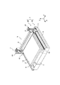
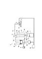
図1は、本発明の一実施形態における塗布装置を示す斜視図であり、図2は、塗布装置を概略的に示した図である。 FIG. 1 is a perspective view showing a coating apparatus according to an embodiment of the present invention, and FIG. 2 is a diagram schematically showing the coating apparatus.
図1、図2に示すように、塗布装置は、供給される薄板状の基板2に薬液やレジスト液等の塗布液(本発明の処理液)を塗布するものである。この塗布装置は、基台3と、基板2を載置するためのテーブル4と、このテーブル4に対し一定方向に移動可能に構成される塗布ユニット5と、この塗布ユニット5に塗布液を供給するレジストポンプ8(本発明の処理液供給装置)とを備えている。
As shown in FIGS. 1 and 2, the coating apparatus applies a coating solution (a processing solution of the present invention) such as a chemical solution or a resist solution to a thin plate-
なお、以下の説明では、塗布ユニット5が移動する方向をX軸方向、これと水平面上で直交する方向をY軸方向、X軸およびY軸方向の双方に直交する方向をZ軸方向とし、図1における手前側を前方、その反対側を後方として説明を進めることとする。 In the following description, the direction in which the coating unit 5 moves is the X-axis direction, the direction orthogonal to this in the horizontal plane is the Y-axis direction, and the direction orthogonal to both the X-axis and the Y-axis direction is the Z-axis direction. The description will proceed with the front side in FIG. 1 as the front and the opposite side as the rear.
前記基台3は、各構成部材、例えばテーブル4及び塗布ユニット5が所定の姿勢を保つように支持するものである。 The base 3 supports each component such as the table 4 and the coating unit 5 so as to maintain a predetermined posture.
前記テーブル4は、搬入された基板2をその表面に載置して保持するものである。具体的には、テーブル4には、その表面に開口する複数の吸引孔が形成されており、これらの吸引孔と真空ポンプ9とが連通して接続されている。そして、テーブル4の表面に基板2が載置された状態で真空ポンプ9を作動させることにより、吸引孔に吸引力が発生し基板2がテーブル4の表面側に吸引されて吸着保持されるようになっている。また、テーブル4には、基板2を昇降動作させる基板昇降機構が設けられている。すなわち、テーブル4の表面には複数のピン孔が形成されており、このピン孔にはZ軸方向に昇降動作可能なリフトピンが埋設されている。これにより、テーブル4の表面に基板2を載置した状態でリフトピンを上昇させることにより、リフトピンの先端部分が基板2に当接した状態で、基板2を所定の高さ位置に保持できるようになっている。
The table 4 is used to place and hold the loaded
前記塗布ユニット5は、テーブル4に載置された基板2に塗布液を塗布するためのものであり、一方向に延び塗布液を吐出する口金部6と、この口金部6の両端部分に設けられたユニット支持部7とを有している。
The coating unit 5 is for applying a coating solution to the
前記ユニット支持部7は、口金部6を昇降動作可能に支持するとともに、この口金部6をX軸方向に移動させるためのものであり、走行装置10とこの走行装置10に支持される昇降装置20とを有している。
The
昇降装置20は、口金部6を昇降動作させるものであり、Z軸方向に延びるレール21と口金部6に連結されるスライダ22とを有している。このレール21には、スライダ22がレール21に沿ってスライド自在に取り付けられている。また、スライダ22にはサーボモータ23により駆動されるボールねじ機構が取り付けられており、このサーボモータ23を駆動制御することにより、スライダ22がZ軸方向に移動するとともに、任意の位置で停止できるようになっている。これにより、口金部6は、Z軸方向への昇降動作が駆動制御され、テーブル4に対して接離可能に動作するようになっている。
The lifting
走行装置10は、口金部6をX軸方向に走行させるためのものであり、走行装置本体11とX軸方向に延びるレール13とを有している。この走行装置本体11は、基台3との間に設けられるエアパッド(不図示)によって基台3上に支持されている。そして、走行装置本体11は、その一部がレール13にスライド自在に取り付けられており、走行装置本体11に取り付けられたリニアモータ12を駆動制御することにより、走行装置本体11がX軸方向に移動するようになっている。これにより、口金部6は、X軸方向に沿って走行することができるようになっている。
The traveling
このように構成されるユニット支持部7により、口金部6は、テーブル4の表面に対してZ軸方向に昇降動作できるとともに、テーブル4の表面から所定高さを維持した状態でテーブル4の表面上をX軸方向に沿って走行できるようになっている。
With the
前記口金部6は、Y軸方向に延びる形状を有する柱状部材であり、テーブル4の表面と対向する対向面には塗布液を吐出するノズル61(図2参照)が形成されている。このノズル61は、テーブル4の表面側に突出し、この突出した部分にはY軸方向に延びる形状のスリットが形成されている。すなわち、このスリットを通じて口金部6に供給された塗布液が基板2の表面に吐出されるようになっている。
The base part 6 is a columnar member having a shape extending in the Y-axis direction, and a nozzle 61 (see FIG. 2) that discharges the coating liquid is formed on an opposing surface that faces the surface of the table 4. The
具体的には、この口金部6の上流側には、塗布液を貯留する塗布液タンクTとレジストポンプ8とが備えられており、レジストポンプ8が、塗布液タンクTの塗布液を口金部6に圧送することにより、口金部6内の塗布液がスリットを通じて吐出されるようになっている。
Specifically, an upstream side of the base part 6 is provided with a coating liquid tank T for storing a coating liquid and a resist
前記レジストポンプ8は、塗布液を口金部6に供給するチューブフラムポンプ8aとチューブフラムポンプ8aを駆動させるポンプ駆動部8bとを有している。
The resist
前記チューブフラムポンプ8aは、ハウジング81とハウジング81内に設けられるチューブ82(本発明の伸縮処理液供給部)とを有しており、このチューブ82が収縮することにより、塗布液が口金部6に供給されるようになっている。
The
具体的には、ハウジング81は、一方向に延びるほぼ円筒状に形成されており、一方端に流出口81bと他方端に流入口81cとを有している。流出口81bは、口金部6と配管D1で連結されており、配管D1のバルブV1が開かれることにより、ハウジング81と口金部6とが連通するようになっている。また、流入口81cは、塗布液タンクTと配管D2で連結されており、配管D2のバルブV2が開かれることにより、ハウジング81と塗布液タンクTとが連通するようになっている。
Specifically, the
また、ハウジング81内には、流体収容室81aが形成されている。この流体収容室81aは、間接液を収容するものであり、ポンプ駆動部8bから供給された間接液を収容できるようになっている。具体的には、流体収容室81aとポンプ駆動部8bとが配管D3で連結されており、この配管D3を通じてポンプ駆動部8bから吐出された間接液が流体収納室81bに供給されるようになっている。
A
そして、この流体収納室81b内に、伸縮変形可能なチューブ82が流体収容室81aとほぼ同軸上に収容されており、その一方端が上述の流出口81bと接続されており、他方端が流入口81cと接続されている。
In the
このチューブ82は、塗布液を口金部6に供給するものである。具体的には、チューブ82は、ハウジング81の径方向に膨張及び収縮変形できるようになっており、チューブ82が膨張することにより塗布液がチューブ82内に流入され、チューブ82が収縮することによりチューブ82内の塗布液が口金部6に吐出できるようになっている。具体的には、流体収容室81a内に間接液が供給されると間接液による圧力がチューブ82に作用する。これにより、チューブ82が収縮し、チューブ82内の塗布液が口金部6に供給されるようになっている。また、流体収容室81aから間接液が排出されると間接液による圧力がチューブ82から解放されるため、チューブ82が膨張し、チューブ82内に塗布液タンクTから配管D2を介して塗布液が流入する。すなわち、チューブ82は、流体収容室81a内の間接液に負荷される圧力により膨張・収縮変形することにより、塗布液をチューブ82内に流入するとともに塗布液を口金部6に供給できるようになっている。
The
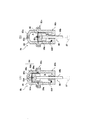
前記ポンプ駆動部8bは、図2、図3に示すように、シリンダ85とプランジャ86とプランジャ駆動部87とを有している。すなわち、プランジャ86がシリンダ85の内部に収容されており、このプランジャ86をプランジャ駆動部87により駆動させることにより、シリンダ85内に間接液の吸入及び排出ができるように構成されている。具体的には、シリンダ85の内部には、膜状シール部材88が設けられており、プランジャ86を動作させることにより膜状シール部材88が変位して流体収容室81aの間接液がシリンダ85に吸入され、シリンダ85から流体収容室81aに間接液が排出されるようになっている。
The
前記シリンダ85は、一軸方向に延びる筒状形状を有しており、上側シリンダ85aと下側シリンダ85bとがフランジ部85cで連結されることによって一体的に形成されている。具体的には、上側シリンダ85aと下側シリンダ85bとは、膜状シール部材88を介して連結されており、この膜状シール部材88によりシリンダ85の内部を軸方向に液溜室aと真空室bとに分離されている。この上側シリンダ85aには、吸排液ポート85eとが形成されている。吸排液ポート85eは、チューブフラムポンプ8aの流体収容室81aと配管D3によって連通して接続されている。これにより、吸排液ポート85eを通じて間接液が流体収容室81a及び液溜室aとを自由に行き来できるようになっている。すなわち、図3(B)に示すように、プランジャ86が下向き(図3において下向き)に変位した場合には、流体収容室81aから吸排液ポート85eを通じて液溜室aに間接液を吸入することができ、また、図3(A)に示すように、プランジャ86が上向き(図3において上向き)に変位することにより、液溜室aから吸排液ポート85eを通じて排出し流体収容室81aに間接液を供給することができるようになっている。すなわち、プランジャ86が上向きに変位することにより流体収容室81aに供給された間接液の圧力がチューブ82に作用することにより、チューブ82が収縮変形し、チューブ82内の塗布液が吐出されるようになっている。
The
また、下側シリンダ85bには、真空ポート85fが形成されており、この真空ポート85fと真空ポンプ9とが連通接続されている。すなわち、真空ポンプ9を作動させて真空室bの圧力を減圧することにより、プランジャ86の下向きへの動きを円滑に行うことができるようになっている。
Further, a vacuum port 85f is formed in the
プランジャ86は、シリンダ85の内径よりも僅かに小さい径を有するヘッド86aと、プランジャ駆動部87と連結される軸部86bとを有している。このプランジャ86のヘッド86aは、液溜室aと対向する位置に、シリンダ85の延びる方向、すなわち、プランジャ86の摺動方向に対してほぼ直交する対向面86cを有しており、この対向面86cの表面が平板状に形成されている。すなわち、プランジャ86がシリンダ85内を摺動すると、ヘッド86aの対向面86cは、摺動方向に対して直交する姿勢を維持した状態で液溜室a側及び液溜室aと反対側に変位するようになっている。したがって、プランジャ86が摺動することにより、液溜室aの容積を単調増加又は単調減少させることができるようになっている。
The
膜状シール部材88は、可撓性材料で形成されており、本実施形態ではポリエステル布の上にゴムを被覆したもので形成され、ほぼ均一厚さの円盤膜形状に形成されている。この膜状シール部材88は、上側シリンダ85a及び下側シリンダ85bのフランジ部85cに挟持される挟持部88a(本発明のハウジング取付部)と、ヘッド86aに取り付けられる平面部88bと、挟持部88a及び取付部88bを連結する余長部88cとを有している。
The film-
挟持部88aは、円盤膜形状の外周部分であり、前記平面部88bの径方向外側に位置する部分である。この挟持部88aは、上側シリンダ85a及び下側シリンダ85bのフランジ部85cによって、外周部分全体に亘って挟圧されており、これにより膜状シール部材88が固定されている。そして、挟持部88aが静止した状態で挟圧されていることにより、挟持部88aとフランジ部85cとの界面が静止状態に保たれている。したがって、間接液が漏れることなく液溜室a内に封止されるようになっている。
The clamping
平面部88bは、プランジャ86のヘッド86aと密着して取り付けられている。本実施形態では、図3に示すように、平面部88bがこのヘッド86aの対向面86cにネジ止めにより固定されている。これにより、膜状シール部材88の平面部88b全体がプランジャ86の動きに追従できるようになっている。すなわち、プランジャ86が上向きに移動することにより、膜状シール部材88の平面部88bが上側に変位し、プランジャ86が下向きに移動することにより、平面部88bが下側に変位するようになっている。これにより、プランジャ86を上向きに移動させて液溜室aの間接液を液溜室aから排出する際、膜状シール部材88の平面部88bがヘッド86aの対向面86cに支持されていることにより、膜状シール部材88の平面部88bが変形することなく間接液を押圧することができるため、プランジャ86の変位(平面部88bの変位)による圧力を間接液を介して直接的にチューブ82に付加させることができる。
The
余長部88cは、余長部分に相当する部分であり、下側シリンダ85bとヘッド86aとの間に収容されている。具体的には、下側シリンダ85bの内壁とヘッド86aとの間には所定寸法の隙間が設定されており、この隙間に湾曲した状態で収容されている。すなわち、挟持部88aから下向きに所定寸法延びた位置で上向きに湾曲変形し、さらに上向きに所定寸法延びて平面部88bに連続的に連結されている。これにより、ヘッド86aが上向きに移動する場合には、余長部88cが下側シリンダ85bの内壁とヘッド86aとの隙間から繰り出され、ヘッド86aが下向きに移動する場合には、前記湾曲部分の形状を維持しつつ前記隙間に収容される。このように、プランジャ86がシリンダ85の軸方向に動作する場合であっても、余長部88cの存在により膜状シール部材88の平面部88b及び余長部88c全体がこのヘッド86aの動きに追従することができる。また、平面部88b及び余長部88cがヘッド86aに追従する場合であっても、挟持部88aは静止状態を維持したままフランジ部85cで挟圧されているため、液溜室a内の間接液は確実に封止される。したがって、間接液は一度封入されれば、特に継ぎ足す必要もなく、メンテナンスも不要となる。
The
前記プランジャ駆動部87は、プランジャ86をシリンダ85の軸方向に駆動させるものである。本実施形態では、サーボモータ83a(図4参照)とボールねじ機構から構成されており、サーボモータ83aを制御することによりプランジャ86の動作を制御できるようになっている。
The
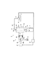
また、本実施形態の塗布装置では、制御装置90が設けられており、予め記憶されたプログラムに従って一連の塗布動作を実行すべく、各種ユニットの駆動装置、プランジャ駆動部87等を駆動制御するとともにこの塗布動作において必要な各種演算が行われるようになっている。
Further, in the coating apparatus of the present embodiment, a
次に、この塗布装置における塗布動作について説明する。なお、これら一連の動作は制御装置90によって制御される。
Next, the application | coating operation | movement in this coating device is demonstrated. These series of operations are controlled by the
まず、基板2の保持が行われる。具体的には、テーブル4の表面から複数のリフトピンが突出した状態で待機されており、これらのリフトピンの先端部分に基板2が載置される。そして、リフトピンを下降させて基板2をテーブル4の表面に載置し、この状態で真空ポンプ9を作動させて吸引孔に吸引力を発生させることにより、基板2をテーブル4の表面上に吸着させて保持させる。
First, the
次に、塗布液の吸い込み動作が行われる。すなわち、テーブル4上にセットされた基板2に必要となる塗布液(基板1枚分)がレジストポンプ8に吸い込まれる。具体的には、初期状態においてバルブV1、V2が閉められているところ、バルブV2を開状態とするとともに、真空ポンプ9を作動させて真空室bが減圧されるとともにプランジャ駆動部87を駆動制御してプランジャ86を真空室b側(図3において下側)に移動させることにより、チューブフラムポンプ8aの流体収容室81aに充填されている間接液がポンプ駆動部8bの液溜室aに吸引される。
Next, a suction operation for the coating liquid is performed. That is, the coating liquid (for one substrate) necessary for the
具体的には、プランジャ86が真空室b側に移動することにより、膜状シール部材88が真空室b側に変位し、液溜室aの容積が拡張される。これにより、チューブフラムポンプ8aの流体収容室81aの間接液に吸引力が作用し、間接液が液溜室aに吸引される。そして、流体収容室81aの間接液が吸引されると、チューブ82に作用していた圧力が減圧されることにより、チューブ82が径方向に膨張する。これにより、塗布液タンクT内の塗布液が吸引され、チューブ82内に塗布液が供給される。
Specifically, when the
次に、塗布液の吐出動作が行われる。すなわち、チューブ82に供給された塗布液を口金部6に供給するとともに、口金部6から基板2上に塗布液を吐出する。具体的には、バルブV2を閉じるととともにバルブV1を開いた状態で、プランジャ駆動部87を駆動制御してプランジャ86を液溜室a側(図3において上側)に移動させることにより、液溜室a内の間接液が押圧されてチューブフラムポンプ8aの流体収容室81a側に移動する。さらに、プランジャ86を液溜室a側に移動させると、間接液が加圧されることにより、間接液による圧力がチューブ82に作用してチューブ82が収縮し、チューブ82内の塗布液が配管D1を通じて口金部6に排出される。そして、さらにプランジャ86を液溜室a側に所定の速度で移動させ続けることにより、チューブ82に圧力が作用し続け口金部6から一定量の塗布液が吐出される。
Next, the discharging operation of the coating liquid is performed. That is, the coating liquid supplied to the
そして、次に口金部6の駆動が行われる。具体的には、走行装置10を駆動制御することにより口金部6を基板2上の所定位置に配置する。そして、昇降装置20を駆動制御することにより口金部6が基板2から所定の高さ位置になるように設定し、この状態から走行装置10を駆動制御することにより、口金部6をX軸方向に走行させる。すなわち、口金部6のスリットから塗布液を吐出させながら口金部6を走行させることにより、基板2上に塗布液が均一厚さで塗布される。
Then, the base 6 is driven next. Specifically, the base unit 6 is disposed at a predetermined position on the
このように、本実施形態における処理液供給装置によれば、プランジャ86は膜状シール部材88の平面部88b全体を変位させて間接液を介してチューブ82に圧力を付加させるため、従来のベローズのように蛇腹部分の伸縮変形により圧力を付加させる場合に比べて、応答性に優れた処理液供給装置及び塗布装置とすることができる。また、前記平面部88bの径方向外側に位置する膜状シール部材88の挟持部88aは、ハウジング85に固定して取り付けられているため、液溜室aに収容される間接液が効果的に封止される。すなわち、プランジャ86の摺動動作により膜状シール部材88の平面部88bが変位した場合であっても、膜状シール部材88の挟持部88a全体は、プランジャ86の摺動動作に影響されず固定された状態を維持しているため、従来のようにプランジャ86とシリンダ85との摺動部分にシールを設ける場合に比べて、作動流体を確実に封止することができる。したがって、液溜室aや流体収容室81a内に空気が混入するのを抑えて、塗布液を安定して供給することができる。
As described above, according to the processing liquid supply apparatus of the present embodiment, the
なお、上記実施形態では、チューブフラムポンプ8aとポンプ駆動部8bとの間に配管D3を配置して流体収容室81aと液溜室aとを連通する例について説明したが、チューブフラムポンプ8aのハウジング81にポンプ駆動部8bを直接取り付けて流体収容室81aと液溜室aとを直接連通して接続するものであってもよい。これにより、配管D3による圧力損失の影響を受けることを回避して、ポンプ駆動部8bからの圧力が直接流体収容室81aのチューブ82に作用させることができる。
In the above embodiment, the example in which the pipe D3 is disposed between the
また、上記実施形態では、膜状シール部材88に余長部88cを設ける例について説明したが、余長部88cを設けずに挟持部88a及び平面部88bからなる円盤状の膜状シール部材88を設けるものであってもよい。この構成であれば、上記実施形態の余長部88cを設ける場合に比べて、プランジャ86のストローク長が小さくなるため、チューブプラムポンプ8aからの吐出量は小さくなるが、プランジャ86により平面部88bを変位させることにより間接液を介してチューブ82に圧力を付加させて塗布液を吐出させることができる。
In the above-described embodiment, the example in which the
また、上記実施形態では、ポリエステル布の上にゴムを被覆した膜状シール部材88を使用する例について説明したが、プラスチックで形成された膜状シール部材88を使用するものであってもよい。この構成によれば、プラスチック材料を適宜選択することにより、ポリエステル布の上にゴムを被覆したものに比べて、対薬品性の優れた膜状シール部材88とすることができる。
Moreover, although the example which uses the film-shaped sealing
2 基板
6 口金部
8 レジストポンプ(処理液供給装置)
8a チューブフラムポンプ
8b ポンプ駆動部
81 ハウジング
82 チューブ(伸縮処理液供給部)
86 プランジャ
88 膜状シール部材
88b 平面部
90 制御装置
2 Substrate 6
8a
86
Claims (4)
前記作動流体収容室に連通して接続され、この作動流体収納室に作動流体を供給又は排出させるポンプ駆動部と
を備える処理液供給装置において、
前記ポンプ駆動部は、前記作動流体収容室に連通する筒状のシリンダと、このシリンダ内を一方向に摺動するプランジャと、シリンダ内に作動流体が収容される液溜部を形成する膜状のシール部とを有しており、
前記シール部は、前記液溜部に対向しプランジャの摺動方向と交差する方向に広がる平面部と、この平面部よりも径方向外側に位置するとともに前記シリンダに固定されるハウジング取付部とを有しており、前記プランジャが前記シール部の平面部全体を液溜部側に変位させて液溜部の容積を小さくさせることにより、前記作動流体収容室に作動流体を供給して前記伸縮処理液供給部から処理液を排出させるとともに、前記プランジャが前記シール部の平面部全体を液溜部と反対側に変位させて液溜部の容積を大きくさせることにより、前記作動流体収容室から作動流体を排出させて前記伸縮処理液供給部に処理液を供給させることを特徴とする処理液供給装置。 A housing having an inflow port for inflowing the processing liquid and an outflow port for discharging the processing liquid, and having a working fluid storage chamber for storing the working fluid; and the operation of the housing in a state of being in communication with the inflow port and the outflow port An expansion / contraction treatment liquid supply section that is disposed in the fluid storage chamber and is capable of expansion and contraction deformation. When the working fluid is supplied to or discharged from the working fluid storage chamber, the expansion / contraction treatment liquid supply section is expanded. A pump unit that supplies the processing liquid into the expansion / contraction processing liquid supply unit and discharges the processing liquid when the expansion / contraction processing liquid supply unit contracts;
In a processing liquid supply apparatus comprising: a pump drive unit that is connected in communication with the working fluid storage chamber and supplies or discharges the working fluid to the working fluid storage chamber;
The pump drive unit is a film that forms a cylindrical cylinder that communicates with the working fluid storage chamber, a plunger that slides in the cylinder in one direction, and a liquid reservoir that stores the working fluid in the cylinder. And a sealing portion of
The seal portion includes a plane portion that faces the liquid reservoir portion and extends in a direction intersecting the sliding direction of the plunger, and a housing mounting portion that is positioned radially outward from the plane portion and fixed to the cylinder. And the plunger displaces the entire planar portion of the seal portion toward the liquid reservoir portion to reduce the volume of the liquid reservoir portion, thereby supplying the working fluid to the working fluid storage chamber and performing the expansion / contraction treatment. The process liquid is discharged from the liquid supply part, and the plunger is operated from the working fluid storage chamber by displacing the entire flat part of the seal part to the opposite side of the liquid storage part to increase the volume of the liquid storage part. A treatment liquid supply apparatus for discharging a fluid and supplying the treatment liquid to the expansion / contraction treatment liquid supply unit.
前記処理液供給装置の流出口と連通し、基板に対し処理液を吐出する口金と、
を備えたことを特徴とする塗布装置。 The processing liquid supply apparatus according to any one of claims 1 to 3,
A base that communicates with the outlet of the processing liquid supply apparatus and discharges the processing liquid to the substrate;
A coating apparatus comprising:
Priority Applications (1)
| Application Number | Priority Date | Filing Date | Title |
|---|---|---|---|
| JP2007259058A JP2009088409A (en) | 2007-10-02 | 2007-10-02 | Treatment liquid supply apparatus and coating apparatus |
Applications Claiming Priority (1)
| Application Number | Priority Date | Filing Date | Title |
|---|---|---|---|
| JP2007259058A JP2009088409A (en) | 2007-10-02 | 2007-10-02 | Treatment liquid supply apparatus and coating apparatus |
Publications (1)
| Publication Number | Publication Date |
|---|---|
| JP2009088409A true JP2009088409A (en) | 2009-04-23 |
Family
ID=40661400
Family Applications (1)
| Application Number | Title | Priority Date | Filing Date |
|---|---|---|---|
| JP2007259058A Pending JP2009088409A (en) | 2007-10-02 | 2007-10-02 | Treatment liquid supply apparatus and coating apparatus |
Country Status (1)
| Country | Link |
|---|---|
| JP (1) | JP2009088409A (en) |
-
2007
- 2007-10-02 JP JP2007259058A patent/JP2009088409A/en active Pending
Similar Documents
| Publication | Publication Date | Title |
|---|---|---|
| JP5416672B2 (en) | Chemical supply device | |
| JP5114527B2 (en) | Liquid supply device | |
| JP2017505884A (en) | Closed loop fluid buffer, two component mixing system with closed loop fluid buffer, and two component mixing system mounted for movement with a dispenser | |
| JP4490320B2 (en) | Coating device | |
| TWI826920B (en) | Liquid supply device | |
| JP2015119160A (en) | Coating device | |
| JP2001038276A (en) | Valve for intermittent supply and intermittently coating apparatus | |
| JPH10137655A (en) | Liquid coating device | |
| US20150096492A1 (en) | Coating apparatus | |
| JP4454350B2 (en) | Chemical supply device | |
| JP2009088409A (en) | Treatment liquid supply apparatus and coating apparatus | |
| JP2009202265A (en) | Coating machine | |
| JP5292121B2 (en) | Piston pump and coating apparatus having the same | |
| JP4024076B2 (en) | Fluid pressure operated valve | |
| JP2009148716A (en) | Painting equipment | |
| JP2009049228A (en) | Pump and substrate processing equipment | |
| TW201821166A (en) | Coating liquid supply device | |
| JP2010207740A (en) | Coating liquid supply device | |
| CN101380621A (en) | Viscous Fluid Applicator | |
| JP6793990B1 (en) | Dispenser | |
| JP4533710B2 (en) | Chemical solution feeder | |
| JP2018008206A (en) | Pretreatment method | |
| JP6797451B1 (en) | Dispenser | |
| JP2698851B2 (en) | Diaphragm pump | |
| JP2013184146A (en) | Coating solution supply device |