JP2009087921A - Backlight containing formed birefringence reflecting polarizer - Google Patents
Backlight containing formed birefringence reflecting polarizer Download PDFInfo
- Publication number
- JP2009087921A JP2009087921A JP2008153293A JP2008153293A JP2009087921A JP 2009087921 A JP2009087921 A JP 2009087921A JP 2008153293 A JP2008153293 A JP 2008153293A JP 2008153293 A JP2008153293 A JP 2008153293A JP 2009087921 A JP2009087921 A JP 2009087921A
- Authority
- JP
- Japan
- Prior art keywords
- light
- reflective polarizer
- lgp
- refractive index
- backlight unit
- Prior art date
- Legal status (The legal status is an assumption and is not a legal conclusion. Google has not performed a legal analysis and makes no representation as to the accuracy of the status listed.)
- Pending
Links
Images


Classifications
-
- G—PHYSICS
- G02—OPTICS
- G02B—OPTICAL ELEMENTS, SYSTEMS OR APPARATUS
- G02B6/00—Light guides; Structural details of arrangements comprising light guides and other optical elements, e.g. couplings
- G02B6/0001—Light guides; Structural details of arrangements comprising light guides and other optical elements, e.g. couplings specially adapted for lighting devices or systems
- G02B6/0011—Light guides; Structural details of arrangements comprising light guides and other optical elements, e.g. couplings specially adapted for lighting devices or systems the light guides being planar or of plate-like form
- G02B6/0033—Means for improving the coupling-out of light from the light guide
- G02B6/0056—Means for improving the coupling-out of light from the light guide for producing polarisation effects, e.g. by a surface with polarizing properties or by an additional polarizing elements
-
- G—PHYSICS
- G02—OPTICS
- G02F—OPTICAL DEVICES OR ARRANGEMENTS FOR THE CONTROL OF LIGHT BY MODIFICATION OF THE OPTICAL PROPERTIES OF THE MEDIA OF THE ELEMENTS INVOLVED THEREIN; NON-LINEAR OPTICS; FREQUENCY-CHANGING OF LIGHT; OPTICAL LOGIC ELEMENTS; OPTICAL ANALOGUE/DIGITAL CONVERTERS
- G02F1/00—Devices or arrangements for the control of the intensity, colour, phase, polarisation or direction of light arriving from an independent light source, e.g. switching, gating or modulating; Non-linear optics
- G02F1/01—Devices or arrangements for the control of the intensity, colour, phase, polarisation or direction of light arriving from an independent light source, e.g. switching, gating or modulating; Non-linear optics for the control of the intensity, phase, polarisation or colour
- G02F1/13—Devices or arrangements for the control of the intensity, colour, phase, polarisation or direction of light arriving from an independent light source, e.g. switching, gating or modulating; Non-linear optics for the control of the intensity, phase, polarisation or colour based on liquid crystals, e.g. single liquid crystal display cells
- G02F1/133—Constructional arrangements; Operation of liquid crystal cells; Circuit arrangements
- G02F1/1333—Constructional arrangements; Manufacturing methods
- G02F1/1335—Structural association of cells with optical devices, e.g. polarisers or reflectors
-
- G—PHYSICS
- G02—OPTICS
- G02B—OPTICAL ELEMENTS, SYSTEMS OR APPARATUS
- G02B6/00—Light guides; Structural details of arrangements comprising light guides and other optical elements, e.g. couplings
- G02B6/0001—Light guides; Structural details of arrangements comprising light guides and other optical elements, e.g. couplings specially adapted for lighting devices or systems
- G02B6/0011—Light guides; Structural details of arrangements comprising light guides and other optical elements, e.g. couplings specially adapted for lighting devices or systems the light guides being planar or of plate-like form
- G02B6/0033—Means for improving the coupling-out of light from the light guide
- G02B6/005—Means for improving the coupling-out of light from the light guide provided by one optical element, or plurality thereof, placed on the light output side of the light guide
- G02B6/0053—Prismatic sheet or layer; Brightness enhancement element, sheet or layer
-
- G—PHYSICS
- G02—OPTICS
- G02F—OPTICAL DEVICES OR ARRANGEMENTS FOR THE CONTROL OF LIGHT BY MODIFICATION OF THE OPTICAL PROPERTIES OF THE MEDIA OF THE ELEMENTS INVOLVED THEREIN; NON-LINEAR OPTICS; FREQUENCY-CHANGING OF LIGHT; OPTICAL LOGIC ELEMENTS; OPTICAL ANALOGUE/DIGITAL CONVERTERS
- G02F1/00—Devices or arrangements for the control of the intensity, colour, phase, polarisation or direction of light arriving from an independent light source, e.g. switching, gating or modulating; Non-linear optics
- G02F1/01—Devices or arrangements for the control of the intensity, colour, phase, polarisation or direction of light arriving from an independent light source, e.g. switching, gating or modulating; Non-linear optics for the control of the intensity, phase, polarisation or colour
- G02F1/13—Devices or arrangements for the control of the intensity, colour, phase, polarisation or direction of light arriving from an independent light source, e.g. switching, gating or modulating; Non-linear optics for the control of the intensity, phase, polarisation or colour based on liquid crystals, e.g. single liquid crystal display cells
- G02F1/133—Constructional arrangements; Operation of liquid crystal cells; Circuit arrangements
- G02F1/1333—Constructional arrangements; Manufacturing methods
- G02F1/1335—Structural association of cells with optical devices, e.g. polarisers or reflectors
- G02F1/1336—Illuminating devices
- G02F1/13362—Illuminating devices providing polarized light, e.g. by converting a polarisation component into another one
Abstract
Description
本発明は、概してディスプレイ照明に関し、より詳細には、大きい入射角を有する光に使用するための成形複屈折に基づく反射偏光子を用いるバックライトユニットに関する。 The present invention relates generally to display illumination, and more particularly to a backlight unit using a reflective polarizer based on shaped birefringence for use with light having a large angle of incidence.
液晶ディスプレイ(LCD)は、様々なディスプレイ装置に広く使用されており、多くのディスプレイ用途向けのより一般的な陰極線管(CRT)モニタと遜色なく競合する。しかしながら、直視型LCDは、解像度、速度および全体的な性能が絶えず良くなっている一方で、ディスプレイの明るさがCRTと比較したときにいまだに満足のいかないことがある。この欠点は、より大きい視野角で特に顕著である。 Liquid crystal displays (LCDs) are widely used in a variety of display devices and compete competingly with the more common cathode ray tube (CRT) monitors for many display applications. However, while direct view LCDs are constantly improving in resolution, speed and overall performance, the brightness of the display may still be unsatisfactory when compared to CRT. This disadvantage is particularly noticeable at larger viewing angles.
明るさを制限するというLCDディスプレイに固有の問題は、偏光依存と関係する。典型的な用途では、LCD装置自体が、光源から放出された非偏光の光の半分を吸収する一対の吸収偏光子を有する。したがって、より明るい光源が設けられた場合でも、この光のかなりの部分が依然として廃棄される。 The inherent problem with LCD displays that limits brightness is related to polarization dependence. In a typical application, the LCD device itself has a pair of absorbing polarizers that absorb half of the unpolarized light emitted from the light source. Thus, even if a brighter light source is provided, a significant portion of this light is still discarded.
この問題に対する1つの解決法が、例えばミネソタ州セントポールの3M社によって製造されているVikuiti(商標)デュアル輝度増強フィルムまたはユタ州オレムのMoxtek社(ユタ州オレム)から入手可能なワイヤグリッド偏光子などの反射偏光子を使用することである。これらの装置は、LCDにとって望ましい偏光を有する光だけを透過し、直交偏光の光を反射し、その光は、照明構成要素によって再配向されて最終的に使用される。 One solution to this problem is, for example, the Vikuiti ™ dual brightness enhancement film manufactured by 3M Company of St. Paul, Minnesota or the wire grid polarizer available from Moxtek of Orem, Utah Is to use a reflective polarizer. These devices only transmit light having the desired polarization for the LCD and reflect orthogonally polarized light, which is redirected by the lighting components and eventually used.
反射偏光子は、光の一部、特に反射偏光子に対する垂線に近い入射角の光に対してうまく機能する。しかしながら、垂線からそれる角度で入射する光、すなわち大角度の光は、有効に使用されていない。この効率の悪さは、光のいくらかの意図的な散乱が導光板(LGP)の中で典型的に行われるので、改善することが困難である。印刷ドットまたはエッチングパターンなどの散乱要素は、従来のバックライトシステムにおいて光を均一にするために大抵必要である。したがって、均一化要素および偏光要素は、相反する目的で機能する傾向があり、適切な明るさと許容できる均一性の両方を達成するためには、ある程度の妥協を必要とする。 Reflective polarizers work well for a portion of light, particularly light at an incident angle close to the normal to the reflective polarizer. However, light incident at an angle deviating from the normal line, that is, light at a large angle, is not effectively used. This inefficiency is difficult to remedy because some intentional scattering of light is typically done in the light guide plate (LGP). Scattering elements such as printed dots or etching patterns are often necessary to make the light uniform in conventional backlight systems. Thus, the homogenizing element and the polarizing element tend to function for conflicting purposes and require some compromise in order to achieve both proper brightness and acceptable uniformity.
反射偏光子または偏光ビームスプリッタを使用する1つの手法は、Liらの米国特許第6,285,423号に開示されているように、この偏光構成要素を、散乱要素のない導光板の底面に配置する(Liらの米国特許第6,285,423号の図1aの符号20を参照)。このタイプの配置では、反射偏光子を透過する光が垂線に近い角度で出力される照明として方向転換される。反射偏光子によって反射された光は、この光の少なくとも一部の偏光を変えるために偏光変換器に向けられ、最終的な出力のために方向転換する。
One approach to using a reflective polarizer or polarizing beam splitter is to place this polarizing component on the bottom of a light guide plate without scattering elements, as disclosed in Li et al. US Pat. No. 6,285,423. (See
反射偏光子を使用する代替手法は、Saccomannoの米国特許第6,443,585号に開示されているように、この要素を、散乱要素のない導光板の上面に配置する(Saccomannoの米国特許第6,443,585号の図1の符号8を参照)。この手法は、散乱の損失が低減されることによって、より高い光取り出し効率を一般に提供するが、満足のいく偏光効果は提供しない。 An alternative approach using a reflective polarizer is to place this element on top of a light guide plate without scattering elements as disclosed in Saccomano US Pat. No. 6,443,585 (Saccomano US Pat. No. 6,443,585 (see reference numeral 8 in FIG. 1). This approach generally provides higher light extraction efficiency by reducing scattering losses, but does not provide a satisfactory polarization effect.
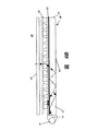
Liらの米国特許第6,285,423号とSaccomannoの米国特許第6,443,585号の両手法を用いて経験した反射偏光子の使用に関する問題を理解するためには、偏光が照明システムの導光板の中でどのように処理されるのかを観察することが有用である。これを行うために、本開示の図1の概略図を、Liらの米国特許第6,285,423号開示の図1AおよびSaccomannoの米国特許第6,443,585号開示の図1と比較する。光線10が、導光板12の入射平面に配置された光源14から放出される。入射平面での入射角がθiであり、θiは、最も一般的な場合に0〜90°である。次いで、光線10は、導光板12内で結合されて、反射偏光子20に入射する。偏光状態は、標準的な概略表記法を用いて表されている。すなわち、S偏光が光線に沿って大きな点で表され、P偏光が光線と直交する線で示されている。導光板12の表面でTIRを無効にするための3つの光取り出し構造25が示されており、バックライト照明技術分野でよく知られているいくつかの異なるフィルムまたは構造が、この目的のために利用され得る。4分の1波長フィルムまたは4分の1波長板などの偏光変換器が、底面18または端面19あるいは底面18と端面19の両面に位置している。
To understand the problems with the use of reflective polarizers experienced using both the Li et al. US Pat. No. 6,285,423 and the Saccomano US Pat. It is useful to observe how the light guide plate is processed. To do this, compare the schematic of FIG. 1 of the present disclosure with FIG. 1A of Li et al., US Pat. No. 6,285,423, and FIG. 1 of Saccomano, US Pat. No. 6,443,585. To do. The
従来の反射偏光子20の詳細な説明は、Liらの米国特許第6,285,423号開示に見ることができる。簡単に言うと、慣例によれば、反射偏光子20は、米国特許第6,285,423号の図8c、図10cおよび図12cに示されているように、(1)ポリカーボネート基体上に堆積された1.38/2.35誘電体層のスタック、(2)基体上の金属層/誘電体層のスタック、(3)2つの基体の間に挟まれた液晶材料などの複屈折材料の層または(4)複屈折材料と等方性材料の混合物を有する延伸プラスチックフィルムを含むいくつかの可能な構造を有することができる。しかしながら、偏光効果は、光が装置の限られた受光角の範囲内にあるときのみ達成されることが強調されなければならない。Liらの米国特許第6,285,423号開示に示されている構成によれば、受光角(Liらの第6,285,423号特許では入射角と称されている)の範囲は、69°〜79°(Liらの第6,285,423号特許の図9を参照)、62°〜82°(Liらの第6,285,423号特許の図11を参照)または70°〜84°(‘Liらの第6,285,423号特許の図13を参照)のいずれかである。
A detailed description of a conventional
角度θTIRに関して、以下の条件が満たされたときに、反射偏光子は、一方の偏光を透過させ、他方の偏光を全内部反射(TIR)によって反射し、そのときに、導光板内に閉じ込められたすべての光の2つの偏光状態を分離する。

Liらの米国特許第6,285,423号開示で使用されている従来の手法に固有の光入射角に関する制限についてより良く理解するためには、反射偏光子20が異常屈折率neおよび正常屈折率noを有する複屈折材料の層である場合の事例をより詳しく見ることが特に有益である。この特定の事例では、neの方向が光源14と平行であるか、または図1Aに示されている入射面に対して垂直である。例としてLiらの米国特許第6,285,423号で使用されている以下の値を使用する。
ne=nLGP=1.589および
no=1.5
In order to better understand the light incident angle limitations inherent in the conventional approach used in the Li et al. US Pat. No. 6,285,423, the
n e = n LGP = 1.589 and n o = 1.5
導光板に閉じこめられた光は受光角θaを有し、受光角θaは以下のように境界される。
51°≦θa<90°
である。したがって、51〜90度の光は、導光板の受光角の範囲内である。
Light confined in the light guide plate has a light-receiving angle theta a, acceptance angle theta a is bounded as follows.
51 ° ≦ θ a <90 °
It is. Therefore, the light of 51 to 90 degrees is within the range of the light receiving angle of the light guide plate.
しかしながら、良好な偏光分離は、全内部反射がある場合にしか、すなわち、
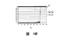
表1ならびに添付の図1B、図1Cおよび図1Dの比較例は、反射偏光子構造に関する従来の手法、例えばLiらの米国特許第6,285,423号開示に記載されている手法の欠点を示す(Liらの米国特許第6,285,423号の第8欄、66〜67行を参照)。これらの例は、nLGP=1.589を有するポリカーボネート基体を示す。図1B〜図1Dでは、様々な受光角θaでのS偏光(入射平面に対して垂直に偏光され、図1Aにおいて円で示されている)の光の透過率の値が曲線T90(黒四角)で与えられる。直交する偏光、すなわちP偏光(入射平面と平行に偏光され、図1Aにおいて線で示されている)の反射率が曲線R0(白三角)で与えられる。図1Bにおいて破線枠Qで示されているように、51〜90度の範囲での光の良好な分離が導光板からの光の偏光に好ましい。光分離は、T90の値とR0の値がともに約0.8を上回ったときに、4:1またはそれ以上の偏光分離が達成されたことを示すので、許容できると考えられる。 Table 1 and the accompanying comparative examples of FIGS. 1B, 1C, and 1D illustrate the shortcomings of conventional approaches for reflective polarizer structures, such as those described in Li et al. US Pat. No. 6,285,423. (See Li et al., US Pat. No. 6,285,423, column 8, lines 66-67). These examples show polycarbonate substrates with n LGP = 1.589. 1B to 1D, the transmittance value of light of S-polarized light (polarized perpendicular to the incident plane and indicated by a circle in FIG. 1A) at various light receiving angles θa is represented by a curve T90 (black). Square). The reflectivity of orthogonally polarized light, ie P-polarized light (polarized parallel to the plane of incidence and shown as a line in FIG. 1A) is given by the curve R0 (white triangle). As indicated by the broken line frame Q in FIG. 1B, good separation of light in the range of 51 to 90 degrees is preferable for polarization of light from the light guide plate. Light separation is considered acceptable as it indicates that 4: 1 or more polarization separation has been achieved when both the T90 and R0 values are above about 0.8.
表1では、屈折率nLGP、neおよびnoに関して、例示的値が与えられている。深さDは、複屈折偏光材料の厚さである。全体的な性能のために特に重要なのが、重なり角の範囲と最右列に与えられている有効受光角θaの範囲である。 In Table 1, the refractive index n LGP, with respect to n e and n o, are given exemplary values. The depth D is the thickness of the birefringent polarizing material. Of particular for overall performance is important, the range of effective light receiving angle theta a given in a range of overlap angle and the rightmost column.
表に示されかつ本開示の説明に使用されている89度の値は、限界として90度に近づく可能性があるが90度未満である受光角θaの角度の値を表すために使用されていることに留意されたい。 And having 89 degrees of the values used in the description of the present disclosure shown in the table, there is a possibility that approaches 90 degrees as a limit is used to represent the value of the angle of acceptance angle theta a is less than 90 degrees Please note that.
深さD=5μmを有する図1Bの例では、重なり角θが71°〜89°であり、これは、所望の51〜90度の範囲の約半分である。51°〜71°の光は、十分に偏光されていない。図1Cの例は、非常に低い正常屈折率no=1.389を有する複屈折層を使用することによって、少なくともいくらかの改善を示している。しかしながら、これは、ne=1.589を所与として、0.2という非常に大きい複屈折をもたらす理論的材料である。ne=1.589を所与として、シート状反射偏光子用にこの値の複屈折を有する使用可能な材料を見いだすことは稀であろう。しかしながら、そのような材料が使用可能な場合でも、重なり角θaは61°〜89°しかなく、これは、まだ所望の範囲には及ばない。 In the example of FIG. 1B with depth D = 5 μm, the overlap angle θ is 71 ° -89 °, which is about half of the desired 51-90 degree range. Light between 51 ° and 71 ° is not sufficiently polarized. The example of FIG. 1C shows at least some improvement by using a birefringent layer having a very low normal index n o = 1.389. However, this is a theoretical material that gives a very large birefringence of 0.2 given n e = 1.589. Given n e = 1.589, it would be rare to find a usable material with this value of birefringence for a sheet-like reflective polarizer. However, even when such materials can be used, the overlap angle [theta] a is only 61 [deg.]-89 [deg.], Which is not yet in the desired range.
図1Dの例は、図1Cの例の理論的材料を使用し、かつ複屈折層の深さDをD=0.5μmに変えることによって、所望の性能にほんの少しだけ近づいている。 The example of FIG. 1D approaches the desired performance only slightly using the theoretical material of the example of FIG. 1C and changing the depth D of the birefringent layer to D = 0.5 μm.
図1B〜図1Dの比較例が示すように、この制限を改善するための従来の解決法は、光学材料自体の物理的特性によって著しく妨げられる。例えば、71〜90度までの機能的なθaの範囲におけるこの制約は、十分に大きい複屈折を有する複屈折材料が使用されれば、いくぶん緩和されるであろう。例えば、0.35より大きい複屈折は、この問題を軽減するであろう。 As the comparative examples of FIGS. 1B-1D show, conventional solutions to improve this limitation are severely hampered by the physical properties of the optical material itself. For example, this constraint in the functional θ a range of 71-90 degrees will be somewhat relaxed if a birefringent material with sufficiently large birefringence is used. For example, birefringence greater than 0.35 will alleviate this problem.
しかしながら、大きい複屈折と他の望ましい特性とを有する材料は、容易に入手できないか、反射偏光子用に使用できないか、あるいは存在さえしない可能性がある。導光板12は、より大きい異常屈折率neおよび正常屈折率noと実質的に同等の屈折率nLGPを有していなければならない。より小さい異常屈折率neおよび正常屈折率noは、通常1.05よりも大きく、そしてそれは、導光板が比較的大きい屈折率nLGP、例えば、1.589というポリカーボネートの屈折率nLGPを有していなければならないことを意味する。しかしながら、これは、最も一般的に使用されている導光板が約1.49の屈折率を有するポリ(メチルメタクリレート)(PMMA)で製作されているので、望ましくないかまたは実行不可能である。したがって、高レベルの複屈折を使用する解決法は、誘電性材料自体の特性に制約される。
However, materials with large birefringence and other desirable properties may not be readily available, cannot be used for reflective polarizers, or may not even exist. The
明らかに、光源14(図1A)から入射する光のかなりの部分は、Liらによって説明され、かつ米国特許第6,285,423号開示の図1に示されている反射偏光子解決法が用いられたときに、使用されない。さらに、この種の従来の解決法では、θaが51〜90度の範囲にある光が利用可能であるが、許容できる偏光分離は、71〜90度の範囲にある光に対してしかもたらされない。導光板に最も一般的に使用されている材料では、導光板の内部で光の角度θaの全範囲にわたって機能する反射偏光子に関する適切な解決法がまだ提供されていない。従来の手法を用いてこの問題を軽減しようとする試みは、光学材料自体の制限によって妨げられている。したがって、従来の反射偏光子技術を用いたときに許容されるよりも広い入射角の範囲にわたって偏光をもたらす照明解決法が必要である。 Obviously, a significant portion of the light incident from the light source 14 (FIG. 1A) is the reflection polarizer solution described by Li et al. And shown in FIG. 1 of US Pat. No. 6,285,423. Not used when used. Furthermore, conventional solutions of this type can use light with θ a in the range of 51-90 degrees, but acceptable polarization separation is only provided for light in the range of 71-90 degrees. Not. The most commonly used materials for light guide plates have not yet provided a suitable solution for reflective polarizers that function over the full range of light angles θa within the light guide plate. Attempts to mitigate this problem using conventional techniques are hampered by limitations of the optical material itself. Therefore, there is a need for an illumination solution that provides polarization over a wider range of incident angles than is acceptable when using conventional reflective polarizer technology.
本発明は、
(1)光源と、
(2)前記光源の方に入射面を有し、かつ屈折率nLGPを有する導光板(LGP)と、
(3)前記LGPと光学的に接触する成形複屈折を有する反射偏光子であって、
(a)屈折率n1を有する細長い非導電性の第1の材料と、
(b)前記第1の材料の屈折率と少なくとも0.2の差で異なる屈折率n2を有する細長い非導電性の第2の材料とを有し、
前記第1の材料および前記第2の材料が、前記LGPの前記入射面に対してほぼ垂直の方向に配列される層を含む反射偏光子とを順に備え、
(i)前記LGPの前記光入射面と平行な面における前記第1および第2の材料の断面寸法が、それらの幅寸法の100nmよりも小さく、および
(ii)前記反射偏光子のパラメータが、少なくとも1つの反射偏光子の光入射角θaで、550nmの波長の光に対して、一方の偏光状態でR0>0.8となり、かつ直交する偏光状態でT90>0.8となるように選択される、バックライトユニットを提供する。
The present invention
(1) a light source;
(2) a light guide plate (LGP) having an incident surface toward the light source and having a refractive index n LGP ;
(3) A reflective polarizer having shaped birefringence in optical contact with the LGP,
(A) an elongated non-conductive first material having a refractive index n 1 ;
(B) an elongated non-conductive second material having a refractive index n 2 that differs by at least 0.2 from the refractive index of the first material;
The first material and the second material sequentially comprise a reflective polarizer including a layer arranged in a direction substantially perpendicular to the incident surface of the LGP,
(I) cross-sectional dimensions of the first and second materials in a plane parallel to the light incident surface of the LGP are smaller than their width dimension of 100 nm, and (ii) the parameters of the reflective polarizer are at least one reflective polarizer on the light incident angle theta a, with respect to light having a wavelength of 550 nm, so that T90> 0.8 in one polarization state R0> 0.8 next and the orthogonal polarization state, Provide a backlight unit to be selected.
本発明の特徴は、本発明が、通常に利用可能な材料を使用して高レベルの偏光分離を得るために成形複屈折を使用することである。 A feature of the present invention is that it uses shaped birefringence to obtain a high level of polarization separation using commonly available materials.
本発明の利点は、本発明が、いくつかのディスプレイ用途で導光板とともに使用するために、必要なレベルの偏光分離を示すことができる照明装置のための反射偏光子を提供することである。 An advantage of the present invention is that it provides a reflective polarizer for a lighting device that can exhibit the required level of polarization separation for use with a light guide plate in some display applications.
本発明のこれらのおよびその他の態様、目的、特徴および利点は、好ましい実施形態についての以下の詳細な説明と添付の特許請求の範囲とを検討し、かつ添付図面を参照することによって、より明確に理解され、かつ評価されるであろう。 These and other aspects, objects, features and advantages of the present invention will become more apparent upon review of the following detailed description of the preferred embodiments and the appended claims, and upon reference to the accompanying drawings. Will be understood and appreciated.
本明細書は、特に本発明の主題を指摘し、かつ明確に主張する請求項で完結するが、本発明は、添付図面に関連して以下の説明がなされたときに、より良く理解されると考えられる。 The specification concludes with claims that particularly point out and distinctly claim the subject matter of the invention, which is better understood when the following description is made in conjunction with the accompanying drawings. it is conceivable that.
本説明は、特に本発明による装置の一部を形成する要素または本発明による装置とより直接的に協働する要素を対象とする。具体的に示されていないかまたは説明されていない要素が当業者に周知である様々な形態をとってもよいことが理解されるべきである。 The present description is particularly directed to elements that form part of the device according to the invention or more directly cooperate with the device according to the invention. It is to be understood that elements not specifically shown or described may take various forms well known to those skilled in the art.
本発明の反射偏光子の構造および配置を示す図は、原寸に留意して描かれてはいないが、全体的な構造、構成および機能を示すように提供される。 Figures showing the structure and arrangement of the reflective polarizer of the present invention are not drawn to scale, but are provided to show the overall structure, configuration and function.
本発明は、成形複屈折の新規な応用を用いることによって、光を導光板の内部で偏光するための角度制限の問題に対処するものである。構造性複屈折とも呼ばれる成形複屈折は、波長よりも小さい特徴と間隔すなわちピッチ寸法とを有するほぼ周期的な構造を有する装置を使用する。成形複屈折の原理は、例えば、十分高い空間周波数を有する導電性ワイヤの回折格子を使用するワイヤグリッド偏光子の形で使用されており、ゼロ次光はもはや回折せず、回折格子特徴と平行な光路長とそれに対して垂直な光路長とが異なるというものである。ワイヤグリッド偏光子の一例が、Kurtzらの「Wire Grid Polarizer」と題する米国特許第6,788,461号に記載されている。これらの従来の解決法は、偏光のために導電性金属ワイヤまたは細長い金属層を用いている。しかしながら、そのような装置は、偏光状態の優れた分離をもたらすことができる一方で、それらの金属材料の使用は、若干の固有光吸収による望ましくない副作用がある。 The present invention addresses the problem of angle limitation for polarizing light inside a light guide plate by using a novel application of shaped birefringence. Molded birefringence, also referred to as structural birefringence, uses a device having a substantially periodic structure with features and spacing or pitch dimensions that are smaller than the wavelength. The principle of shaping birefringence is used, for example, in the form of a wire grid polarizer using a conductive wire diffraction grating with a sufficiently high spatial frequency, the zero order light no longer being diffracted and parallel to the diffraction grating features. The optical path length is different from the perpendicular optical path length. An example of a wire grid polarizer is described in US Pat. No. 6,788,461 entitled “Wire Grid Polarizer” by Kurtz et al. These conventional solutions use conductive metal wires or elongated metal layers for polarization. However, while such devices can provide excellent separation of polarization states, the use of these metallic materials has undesirable side effects due to some intrinsic light absorption.
しかしならが、本発明では、反射性および導電性のワイヤを使用するのではなく、光伝播の全体的な方向に沿って延びる、一方が高い屈折率n1を有し、他方が低い屈折率n2を有する、2つの誘電性/非導電性材料を含む層が形成される。2つの誘電性材料は、等方性または複屈折とすることができる。例示のために、本開示に与えられているすべての実施例は、2つの誘電性材料が等方性であること、すなわち各材料が1つの屈折率しか有していないことを前提とする。本発明で得られる反射偏光子は、成形複屈折がこの配置でもたらされるように構造化され、したがって、層の挙動は、有効な異常屈折率neおよび正常屈折率noを有する高複屈折材料層の挙動とほぼ同じである。この場合、成形複屈折構造の結果として得られた有効な異常屈折率neおよび異常屈折率noは、元の材料の屈折率n1およびn2とは一般に異なる。この構造の成形複屈折は、常に負数、すなわちΔn=ne−no<0として計算される。しかしながら、実際には、差は対象量であるので、絶対値|Δn|を使用して、複屈折を定量化することができる。比較として、n1およびn2の一方または両方が、通常は導電性材料の場合に複素数であり、したがって、成形複屈折もまた複素数である。この配置は、導電性材料を使用した場合に若干の固有吸収があることを意味する。 However, in the present invention, rather than using reflective and conductive wires, one has a high index of refraction n 1 and the other has a low index of refraction extending along the general direction of light propagation. A layer comprising two dielectric / non-conductive materials having n 2 is formed. The two dielectric materials can be isotropic or birefringent. For purposes of illustration, all examples given in this disclosure assume that the two dielectric materials are isotropic, i.e., each material has only one refractive index. Reflective polarizer obtained by the present invention is structured as formed birefringence is effected by this arrangement, therefore, the behavior of the layer is high birefringence having effective extraordinary index n e and ordinary index n o The behavior of the material layer is almost the same. In this case, the effective extraordinary index n e and the extraordinary refractive index n o which is obtained as a result of formed birefringence structures generally different from the refractive index n 1 and n 2 of the original material. Formed birefringence of this structure is always calculated negative, that is, as Δn = n e -n o <0 . However, in practice, the difference is a target quantity, so the absolute value | Δn | can be used to quantify birefringence. As a comparison, one or both of n 1 and n 2 are usually complex in the case of conductive materials, and thus the shaped birefringence is also complex. This arrangement means that there is some intrinsic absorption when using conductive materials.
本発明による反射偏光子は、ディスプレイ用途にとって特定の価値のある3つの重要な利点を有する。第1に、この装置は、単一の複屈折材料を使用する従来の反射偏光子で得られる複屈折を優に上回る、0.2〜0.5またはそれ以上の範囲にある高レベルの複屈折|Δn|を提供する。これは、一方が1.0(空気)という低い低屈折率n2を有し、他方が1.6〜1.8(一部のプラスチックによる)という大きい屈折率n1、あるいは2.35(TiO2などの無機材料を使用)という大きい高屈折率n1を有する、2つの等方性材料で可能となる。第2に、有効な正常屈折率noは、低い値に調整することができる。したがって、no=nLGP>ne(式中、nLGPはLGP基体の屈折率であり、前述のように、背面照明装置に反射偏光子を使用した場合に重要な関係である)を満たす低屈折率を有するLGP基体を使用することが可能である。第3に、この反射偏光子は、誘電性/非導電性材料の場合にn1およびn2がどちらも実数であるので、ほとんど吸収しない。前述のように、これは、若干の固有吸収を示す従来の導電性ワイヤグリッド偏光子とは対照的である。 The reflective polarizer according to the invention has three important advantages of particular value for display applications. First, this device has a high level of birefringence in the range of 0.2 to 0.5 or more, well above the birefringence obtained with conventional reflective polarizers using a single birefringent material. Refraction | Δn | is provided. This is because one has a low refractive index n 2 as low as 1.0 (air) and the other as a large refractive index n 1 between 1.6 and 1.8 (depending on some plastics), or 2.35 ( This is possible with two isotropic materials having a large high refractive index n 1 ( using inorganic materials such as TiO 2 ). Second, the effective ordinary index n o can be adjusted to a lower value. Therefore, satisfy n o = n LGP > n e (where n LGP is the refractive index of the LGP substrate, and as described above, this is an important relationship when a reflective polarizer is used in the backlight device). It is possible to use an LGP substrate having a low refractive index. Third, this reflective polarizer absorbs very little because n 1 and n 2 are both real numbers in the case of dielectric / non-conductive materials. As mentioned above, this is in contrast to conventional conductive wire grid polarizers that exhibit some intrinsic absorption.
図2Aの斜視図は、本発明による成形複屈折に基づく反射偏光子50と光学的に接触する導光板12を備えるバックライト装置38を示す。導光板12は、光源14に面する入射面16を有する。図2Aに示されているように、反射偏光子50は、導光板12と他の透明基体材料の層、典型的には導光板12と同じ屈折率を有する材料の層との間に挟まれていてもよい。
The perspective view of FIG. 2A shows a
反射偏光子50は、導光板12と光学的に接触している。本開示で使用される用語「光学的接触」は、物理的接触と同等であり、または任意に光学接着剤によって結合することと同等である。反射偏光子50と導光板12との間に空隙はない。
The
反射偏光子50は、入射面16に対してほぼ垂直である長さ方向に延長され、かつ交互パターンで幅方向に分散されている、複数の細長いチャネル31および32を有する。チャネルは、入射面に対して90°であるか、または±15度の範囲内にあれば、ほぼ垂直である。各チャネル31、32は、非導電性または誘電性の光学材料を使用して形成される。図2Aおよび図2Bの断面に示されているように、チャネル31および32は、異なる屈折率n1およびn2を有する。寸法に関して、チャネル31および32は、幅が可視波長域の光の波長未満、通常は約150nm未満であり、紙面と平行な方向、すなわち入射面16に対して垂直な方向に反射偏光子50の長さに沿って延びる。したがって、反射偏光子50は、有効な異常屈折率neおよび正常屈折率noを有する。異常屈折率neの方向は、チャネル31および32の長さ方向に対して垂直である。そして、屈折率noは、neに対して垂直な偏光軸を有する光に適用される。
The
比較例では、図2Aに示されている方向と直交する方向、すなわち入射面16と平行な方向に延びるチャネル31および32を検討する。この配置により、異常屈折率neの方向は、光源14の長さ方向に対して垂直になる。したがって、入射平面で偏光された光は、neとnoの組み合わせに直面して、反射偏光子の表面で全内部反射を維持することが困難になるはずである。
In the comparative example, consider
図2Bは、反射偏光子50の偏光挙動を決定するいくつかの重要な寸法を示す。これらは、
w1:チャネル31の断面幅;
w2:チャネル32の断面幅;
P:チャネル31および32のピッチ、この場合(w1+w2)に等しい;
d:チャネル31および32の深さ
を含む。1つの重要な寸法関係が、曲線因子f1、すなわちデューティサイクルであり、これは次のように表すことができる。
f1=w1/P
FIG. 2B shows some important dimensions that determine the polarization behavior of the
w 1 : cross-sectional width of the
w 2 : the cross-sectional width of the
P: the pitch of
d: Includes the depth of
f 1 = w 1 / P
本開示との関連で、ピッチPは、製作の結果としてピッチが若干変動し得る場合の平均ピッチを含むものである。 In the context of this disclosure, pitch P includes the average pitch where the pitch may vary slightly as a result of fabrication.
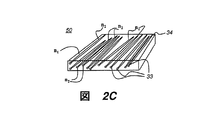
図2Cは、反射偏光子50の別の実施形態を示し、この反射偏光子50は、マトリックス材料34の中に埋め込まれた分散材料33を有し、分散材料33は、図2Bの周期的パターンと同じ応答を示すことができるが、非周期的分布のチャネルを有する交互パターンで配置されている。分散材料33は、マトリックス材料34よりも高いまたは低い屈折率を有することができる。埋め込まれた材料の幅寸法は、可視光の波長と比べて小さく、好ましくは150nmより小さく、より好ましくは100nmより小さい。ピッチPは、150nm未満であることが好ましい。埋め込まれた材料の形状は、細長いことが好ましい。マトリックス材料および分散材料は、等方性材料または複屈折材料とすることができる。大きい成形複屈折の値が、この構成からも提供され得る。埋め込まれた(または分散された)材料の体積分率は、図2Bに示されている反射偏光子の曲線因子f1に関係する。
FIG. 2C shows another embodiment of a
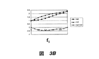
図2Aおよび図2Bの成形複屈折の実施形態について、図3A〜図3Dのグラフは、有効な異常屈折率neおよび正常屈折率noならびに複屈折Δn=ne−noを曲線因子f1の関数として示す。垂直入射の下で、有効屈折率neおよびnoは、ゼロ次有効媒質理論によって与えられる。 Embodiments of formed birefringence in Figures 2A and 2B, the graph of FIG 3A~ Figure 3D, the effective extraordinary index n e and ordinary index n o and the birefringence [Delta] n = n e -n o fill factor f Shown as a function of 1 . Under normal incidence, the effective refractive index n e and n o is given by the zero-order effective medium theory.
一般に、ゼロ次値は、以下のように、ピッチPが入射光の波長に対して非常に小さい場合に適用されるのが最良である。
図3A(ゼロ次の場合)および図3B(2次の場合)では、それぞれの屈折率が、n1=2.35、n2=1.0である。例えば、図3Aでは、約−0.5という比較的高い複屈折の値が、約0.6の曲線因子f1の値を用いて得ることができる。 In FIG. 3A (in the case of zero order) and FIG. 3B (in the case of second order), the respective refractive indexes are n 1 = 2.35 and n 2 = 1.0. For example, in FIG. 3A, a relatively high birefringence value of about −0.5 can be obtained using a fill factor f 1 value of about 0.6.
図3C(ゼロ次の場合)および図3B(2次の場合)では、それぞれの屈折率が、n1=1.8、n2=1.0である。 In FIG. 3C (in the case of zero order) and FIG. 3B (in the case of secondary order), the respective refractive indexes are n 1 = 1.8 and n 2 = 1.0.
要約すると、図3A〜図3Dから、比較的大きい複屈折値(この場合も絶対値で)が、上述の細長いチャネル配置を用いて、2つの通常の等方性誘電性材料を使用して得ることができることが分かる。 In summary, from FIGS. 3A-3D, relatively large birefringence values (again in absolute value) are obtained using two conventional isotropic dielectric materials using the elongated channel arrangement described above. I can see that
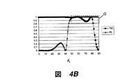
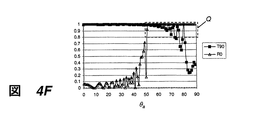
図4A〜図4Fおよび図5A〜図5Jは、本発明による成形複屈折をベースとして、屈折率nLGP、n1、n2、深さdおよび曲線因子f1に関していくつかの異なる考えられる値を用いた反射偏光子のいくつかの実施例を示す。図4A〜図4Fの実施例の場合、LGP12の基体は、nLGP=1.589を有するポリカーボネートである。図5A〜図5Jの実施例の場合、LGP12の基体は、nLGP=1.49を有するPMMAである。図4A〜図4Fおよび図5A〜図5Hの実施例では、ピッチPは140nmであり、対象の波長は550nmである。実施例5Iおよび5Jでは、ピッチPは100nmであり、対象の波長は、同様に550nmである。 FIGS. 4A-4F and FIGS. 5A-5J are based on molding birefringence according to the present invention and have several different possible values for refractive index n LGP , n 1 , n 2 , depth d and fill factor f 1. Several examples of reflective polarizers using are shown. In the example of FIGS. 4A-4F, the substrate of LGP 12 is polycarbonate with n LGP = 1.589. In the example of FIGS. 5A-5J, the LGP 12 substrate is PMMA with n LGP = 1.49. In the example of FIGS. 4A-4F and 5A-5H, the pitch P is 140 nm and the wavelength of interest is 550 nm. In Examples 5I and 5J, the pitch P is 100 nm and the wavelength of interest is 550 nm as well.
図4A〜図5Jに示されている基準破線枠Qは、対象の受光角θaの範囲、この場合には51〜90度を示し、本発明の反射偏光子と先に図1B〜図1Dに示したような従来の反射偏光子との比較を容易にする。 Figure 4A~ Figure 5J reference dashed box Q shown in the range of acceptance angles theta a to the subject, in this case represents a 51 to 90 degrees, 1B~-1D to the reflective polarizer and the previous invention Comparison with a conventional reflective polarizer as shown in FIG.
解析が、厳密結合波解析(RCWA)を用いてサブ波長構造を完全にモデル化できるようにするGsolverグレーティング解析ソフトウェアツールを用いて、550nmでモデル化された。Gsolverソフトウェアは、テキサス州アレン,P.O.Box 353のGrating Solver Development社から市販されている。 The analysis was modeled at 550 nm using a Gsolver grating analysis software tool that allows the subwavelength structure to be fully modeled using exact coupled wave analysis (RCWA). Gsolver software is available from Allen, Texas, P.M. O. Box 353 is commercially available from Grafting Solver Development.
ポリカーボネート基体での実施例(図4A〜4F)
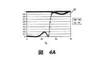
図4Aの実施例を参照すると、基体の屈折率は、nLGP=1.589であり、したがって、導光板に閉じこめられた光の受光角θaは、先にLiらの第6,285,423号特許で与えられた例を参照して説明し、かつ図1B、図1Cおよび図1Dのグラフで要約したように、51°≦θa<90°で与えられた範囲内にある。高屈折率n1は2.35であり、低屈折率n2は1.0である。高屈折率材料の曲線因子は、f1=0.38である。反射偏光子の厚さは0.5mmである。
Example with polycarbonate substrate (FIGS. 4A-4F)
Referring to the example of FIG. 4A, the refractive index of the substrate is n LGP = 1.589, and therefore the light receiving angle θ a of the light confined in the light guide plate is the same as that of Li et al. As described with reference to the example given in the '423 patent and summarized in the graphs of FIGS. 1B, 1C and 1D, it is within the range given by 51 ° ≦ θ a <90 °. The high refractive index n 1 is 2.35 and the low refractive index n 2 is 1.0. The fill factor of the high refractive index material is f 1 = 0.38. The thickness of the reflective polarizer is 0.5 mm.
チャネル31および32と平行な面で偏光された光の場合、その光は、有効な正常屈折率noおよびLGP12の基体の屈折率nLGPに遭遇する。透過率対受光角の挙動は、曲線T90(黒四角)で記載されている。材料の吸収は小さく、ほぼゼロと見なされるので、反射は、R90=1−T90であり、プロットされていない。破線枠Q内に示されているように、透過値T90は、すべての所望の受光角に対して88%を上回っており、この偏光の光は、反射偏光子を実質的に透過することを示す。
For polarized in a plane parallel to the
チャネル31、32に対して垂直な面で偏光された光の場合、有効な異常屈折率neおよび基体の屈折率nLGPが適用される。反射対受光角の特性は、曲線R0(白三角)で表される。この場合も、透過率T0=1−R0はプロットされていない。R0は、58°より大きいすべての入射角に対して90%を上回っており、この偏光の光は、反射偏光子から反射されたことを示す。R0は、51°≦θa<90°に対して80%の閾値を超えており、この反射偏光子は、導光板内で結合された本質的にすべての光に対して十分に機能することを示す。
For light polarized in a plane perpendicular to
図4Aに示されている性能が与えられると、本発明のこの反射偏光子の実施形態は、図1B〜図1Dを参照して説明したような従来の反射偏光子に対して著しい改善をもたらして、偏光状態が広範囲の受光角θaにわたって十分に有効に分離することが分かる。 Given the performance shown in FIG. 4A, this reflective polarizer embodiment of the present invention provides a significant improvement over conventional reflective polarizers as described with reference to FIGS. 1B-1D. Thus, it can be seen that the polarization state is sufficiently effectively separated over a wide light receiving angle θa.
下記の表2は、図4A〜図4Fに適用されているパラメータおよび性能の値の概要を示す。表2の実施例のすべてについて、屈折率は、nLGP=1.589、n1=2.35、n2=1.0およびピッチP=140nmである。深さdおよび曲線因子f1の値は、個々の実施例で異なる。 Table 2 below provides an overview of the parameters and performance values applied in FIGS. 4A-4F. For all of the examples in Table 2, the refractive indices are n LGP = 1.589, n 1 = 2.35, n 2 = 1.0 and pitch P = 140 nm. The values of the depth d and the fill factor f 1 are different for each example.
図4Aの曲線を参照して説明する実施例1は、d=0.5μm、f1=0.38であり、偏光分離に関して最高の性能をもたらして、重なり角θaの範囲(ただし、T90>0.8およびR0>0.8)は、50°から89°まで広がっている。 Example 1 described with reference to the curve of FIG. 4A has d = 0.5 μm, f 1 = 0.38, which provides the best performance with respect to polarization separation, and the range of overlap angle θ a (where T90 > 0.8 and R0> 0.8) extend from 50 ° to 89 °.
図4Bに示されている実施例2は、曲線因子f1=0.30を除いて、実施例1で与えられた値を使用している。重なり角θaの範囲は、46°〜82°であり、下限で広がっているが、高角度の光に対しては最適でない。 Example 2 shown in FIG. 4B uses the values given in Example 1 except for the fill factor f 1 = 0.30. The range of the overlap angle [theta] a is 46 [deg.] To 82 [deg.], Which extends at the lower limit, but is not optimal for high angle light.
図4Cに示されている実施例3は、曲線因子f1=0.50を除いて、実施例1で与えられた値を使用している。重なり角θは、59°〜77°であり、この範囲は、上限に対しても下限に対しても狭くなっている。 Example 3 shown in FIG. 4C uses the values given in Example 1 except for the fill factor f 1 = 0.50. The overlap angle θ is 59 ° to 77 °, and this range is narrower than the upper limit and the lower limit.
図4Dに示されている実施例4は、深さd=0.40μmを除いて、実施例1で与えられた値を使用している。重なり角θは、51°〜79°であり、この範囲は、下限がほぼ同じであり、上限が狭くなっている。 Example 4 shown in FIG. 4D uses the values given in Example 1 except for the depth d = 0.40 μm. The overlapping angle [theta] is 51 [deg.] To 79 [deg.], And the lower limit of this range is substantially the same, and the upper limit is narrow.
図4Eに示されている実施例5は、深さd=0.60μmを除いて、実施例1で与えられた値を使用している。重なり角θは、50°〜72°であり、この範囲は、下限がほぼ同じであり、上限が狭くなっている。 Example 5 shown in FIG. 4E uses the values given in Example 1 except for the depth d = 0.60 μm. The overlapping angle [theta] is 50 [deg.] To 72 [deg.], And in this range, the lower limit is substantially the same and the upper limit is narrow.
図4Fに示されている実施例6は、深さd=5.0μmを除いて、実施例1で与えられた値を使用している。重なり角θは、51°〜72°であり、この範囲は、下限および上限が図4Eの実施例とほぼ同じである。 Example 6 shown in FIG. 4F uses the values given in Example 1 except for the depth d = 5.0 μm. The overlap angle [theta] is 51 [deg.] To 72 [deg.], And this range has a lower limit and an upper limit that are substantially the same as the embodiment of FIG.
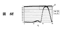
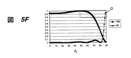
PMMA基体での実施例(図5A〜図5J)
表3に要約されている図5A〜図5Jの実施例は、図4A〜図4Fの実施例で与えられたパラメータとはわずかに異なるパラメータ、とりわけ異なる基体屈折率nLGPを有する本発明による反射偏光子の性能を示す。これらの実施例では、LGP屈折率nLGP=1.49であり、したがって、導光体内に閉じこめられた光の受光角θaは、約48°≦θa<90°で与えられる範囲にある。前述したように、最も一般的に使用されている導光板材料は、約1.49の屈折率を有するPMMAである。図5A〜図5Jに示されている基準破線枠Qは、0.8を上回るT90およびR0の値で、対象の受光角θaの範囲、約48〜90度を示し、本発明の反射偏光子と、先に図1B〜図1Dに示したような従来の反射偏光子と、図4A〜4Fの本発明の実施例との比較を容易にする。
Example with PMMA substrate (FIGS. 5A-5J)
The embodiment of FIGS. 5A-5J summarized in Table 3 is a reflection according to the invention having slightly different parameters than those given in the embodiment of FIGS. 4A-4F, in particular a different substrate refractive index n LGP. The performance of a polarizer is shown. In these embodiments, LGP refractive index n LGP = 1.49, and therefore the light reception angle θ a of the light confined in the light guide is in a range given by about 48 ° ≦ θ a <90 °. . As mentioned above, the most commonly used light guide plate material is PMMA having a refractive index of about 1.49. Reference dashed box Q shown in FIG 5A~ Figure 5J is a value of T90 and R0 above 0.8, the range of acceptance angles theta a to the subject, showed about 48-90 degrees, the reflected polarization of the present invention This facilitates comparison of the polarizer, the conventional reflective polarizer as previously shown in FIGS. 1B-1D, and the embodiments of the present invention of FIGS.
最初に図5Aを参照すると、高屈折率n1は1.80であり、低屈折率n2は1.0である。ピッチPは、140nmである。高屈折率材料の曲線因子f1は、0.524である。反射偏光子の厚さは、0.5mmである。この場合、反射R0は、約59°より大きい受光角θaに対して80%を上回っており、この偏光の光は、反射偏光子から反射されたことを示す。したがって、この反射偏光子の設計は、従来の反射偏光子に対して大幅に改善されるが、与えられた先の実施例のうちの一部ほど良くはない。 Referring first to FIG. 5A, the high refractive index n 1 is 1.80 and the low refractive index n 2 is 1.0. The pitch P is 140 nm. The fill factor f 1 of the high refractive index material is 0.524. The thickness of the reflective polarizer is 0.5 mm. In this case, the reflection R0 exceeds 80% for a light receiving angle θa of greater than about 59 °, indicating that this polarized light is reflected from the reflective polarizer. Thus, the design of this reflective polarizer is a significant improvement over conventional reflective polarizers, but not as good as some of the previous examples given.
図5Bの実施例では、高い屈折率n1は、Liらの米国特許第6,285,423号開示において使用されているもの(米国特許第6,285,423号開示における図12および13を参照)に対応する1.589である。低屈折率n2は1.0である。高屈折率材料の曲線因子f1は0.787である。チャネル31および32と平行な面で偏光された光の場合、その光は、正常屈折率noおよびLGP12の基体の屈折率nLGPに遭遇する。透過T90は、すべての受光角θaに対して95%を上回る。反射R0は、71°より大きい受光角に対して80%を上回る。R0は、67.5°≦θa<90°に対して50%を上回る。この反射偏光子が、より低い屈折率(1.49対1.589)を有する基体を使用するという利点とともに、従来の反射偏光子と同等の偏光分離効果を有することを観察することができる。したがって、受光角θaの全範囲が期待はずれであっても、性能は、Liらの米国特許第6,285,423号開示に記載されているものと少なくとも同等であるが、Liらの解決法が用いている一般的ではないポリカーボネート材料ではなく、標準的なLGP12の材料(PMMA)を使用している。
In the example of FIG. 5B, the high refractive index n 1 is that used in the Li et al. US Pat. No. 6,285,423 disclosure (see FIGS. 12 and 13 in the US Pat. No. 6,285,423 disclosure). 1.589 corresponding to the reference). Low refractive index n 2 is 1.0. The fill factor f 1 of the high refractive index material is 0.787. For polarized in a plane parallel to the
図5Cの実施例は、層の厚さdが5μmであり、かつ高屈折率材料の曲線因子f1が0.785であることを除いて、図5Bの実施例とほぼ同等である。全体的な分離性能は、Liらの米国特許第6,285,423号開示に記載されているものとほぼ同等である。 The embodiment of FIG. 5C is substantially the same as the embodiment of FIG. 5B except that the layer thickness d is 5 μm and the fill factor f 1 of the high refractive index material is 0.785. The overall separation performance is approximately equivalent to that described in Li et al. US Pat. No. 6,285,423.
図5Dの実施例は、図5Bの実施例とほぼ同等であるが、高屈折率n1が2.35である。図5Eの実施例は、図5Dの実施例とほぼ同等であるが、曲線因子f1が0.45である。図5Fの実施例は、図5Dの実施例とほぼ同等であるが、f1が0.6である。この場合、偏光分離が許容できる重なり領域がない。同様に、図5Gは、深さd=0.4μmを有し、かつ重なりのない実施例を示す。図5Hは、図5Gの実施例とほぼ同等の実施例を示すが、深さd=0.6μmを有し、重なりが非常に狭い。図5Iは、類似の実施例を示すが、ピッチPが140nmではなく100nmである。図5Jは、類似の実施例を示すが、曲線因子f1が0.534である。曲線因子f1がわずかに変化すると、層の厚さが変化することによって、干渉効果を最小限に抑えることに留意されたい。 The embodiment of FIG. 5D is substantially the same as the embodiment of FIG. 5B, but has a high refractive index n 1 of 2.35. The embodiment of FIG. 5E is substantially equivalent to the embodiment of FIG. 5D, but the fill factor f 1 is 0.45. The embodiment of FIG. 5F is substantially equivalent to the embodiment of FIG. 5D, but f 1 is 0.6. In this case, there is no overlapping region where polarization separation is acceptable. Similarly, FIG. 5G shows an embodiment with a depth d = 0.4 μm and no overlap. FIG. 5H shows an embodiment that is substantially equivalent to the embodiment of FIG. 5G, but with a depth d = 0.6 μm, and the overlap is very narrow. FIG. 5I shows a similar embodiment, but the pitch P is 100 nm instead of 140 nm. FIG. 5J shows a similar embodiment, but the fill factor f 1 is 0.534. Note that a slight change in fill factor f 1 minimizes the interference effect by changing the layer thickness.
図4A〜図4Fおよび図5A〜図5Jに与えられている実施例は、限定するものではなく、例示するためのものである。他の多くのパラメータ変動が許容される。例えば、チャネル31、32の形状は、図2Aおよび図2Bに示されている矩形断面と異なることができ、当技術分野で知られる他の形状を使用することもできる。ピッチPは、ゼロ次回折しか生じない限り、長くすることも短くすることもできる。低屈折材料は、空気である必要はなく、比較的低い屈折率を有する、例えばMgF2などの種々の材料のうちのいずれかとすることもできる。高屈折率材料と低屈折率材料は、どちらもそれらの光学軸が平行に向けられている限り、複屈折とすることができる。
The examples given in FIGS. 4A-4F and 5A-5J are intended to be illustrative rather than limiting. Many other parameter variations are acceptable. For example, the shape of the
製作
いくつかの異なる製作技術のうちのいずれかが、反射偏光子50を形成するために使用され得る。チャネル32に空気を用いた一実施形態では、チャネル構造は、標準的なフォトリソグラフィを用いてチャネル31を形成することになる基体に直接パターン化され得る。他の方法では、インクジェット印刷または他の精密堆積技術を用いた、基体上への材料31の堆積を使用することができる。
Fabrication Any of several different fabrication techniques can be used to form the
フォトリソグラフィを用いる代替方法では、金属層が、後続のエッチングのためのマスクとして付着され得る。この場合、金属層は、アルミニウムなどの金属を使用して堆積される。堆積法は、熱蒸着やスパッタリングなどのいくつかの標準的な方法のうちの1つとすることができる。次に、金属は、標準的なフォトリソグラフィとそれに続くメタルエッチ(あるいは、CC14、BC13などのドライメタルエッチ)を用いてパターン化されて、マスクパターンを形成する。次いで、チャネル32は、好ましくない材料を除去するようにエッチングされて、所望の空隙を残すことができる。
In an alternative method using photolithography, a metal layer can be deposited as a mask for subsequent etching. In this case, the metal layer is deposited using a metal such as aluminum. The deposition method can be one of several standard methods such as thermal evaporation or sputtering. The metal is then patterned using standard photolithography followed by a metal etch (or dry metal etch such as CC14, BC13, etc.) to form a mask pattern. The
あるいは、誘電体を繰り返しエッチングしたり、イオンビーム加工したりする方法も使用され得る。リフトオフ法も使用され得る。SiO2エッチのためにHFなどのエッチング化合物を用いたウェットエッチが使用され得る。 Alternatively, a method of repeatedly etching a dielectric or ion beam processing may be used. A lift-off method can also be used. A wet etch using an etch compound such as HF may be used for the SiO2 etch.
他の実施形態では、複数の誘電性材料層が、チャネル31および32のどちらか一方または両方を形成するように堆積され得る。このタイプの製作では、適正な深さd(図2B)が達成されるまで、堆積プロセスとエッチングプロセスが繰り返される必要がある。
In other embodiments, multiple dielectric material layers may be deposited to form either or both of
図2Cに示されている実施形態を再び参照すると、反射偏光子を製作する別の方法では、ボイド空気が、適切な屈折率を有する無機または有機バインダと混合される。次いで、媒質は、一方向に沿って延伸される。ボイド空気の寸法は、この方向の光の波長よりも小さく、かつ直交方向の光の数波長分よりも大きい。ボイドとバインダの相対比は、有効な異常屈折率neおよび正常屈折率noを決定するチャネルの曲線因子f1に等しい。 Referring back to the embodiment shown in FIG. 2C, in another method of making a reflective polarizer, void air is mixed with an inorganic or organic binder having an appropriate refractive index. The medium is then stretched along one direction. The size of the void air is smaller than the wavelength of light in this direction and larger than several wavelengths of light in the orthogonal direction. The relative ratio of voids and the binder is equal to the fill factor f 1 of the channel to determine the effective extraordinary index n e and ordinary index n o.
本発明の反射偏光子50は、考えられる様々な実施形態でディスプレイ背面照明として使用することができる。図6Aを参照すると、反射偏光子50が、テーパ状導光板30、およびディスプレイ36内の光方向転換フィルム26と光学的に接触して使用される。この背面照明構成要素の組み合わせは、LCD変調器40によって偏光した光を方向付け、光利用効率を高め、および通常はLCD変調器40の一部として設けられる偏光構成要素の要件を減らす。偏光変換器、例えば4分の1波長フィルムまたは4分の1波長板が、底面18および/または端面19上に配置されることに留意されたい。
The
図6Bは、平坦なまたは非テーパ状の導光板12と光学的に接触して使用される反射偏光子50を示す。破線で示されているような別個のフィルムに接触しているか、あるいは基体表面に直接形成されるかまたは付着された光取り出し構造25が、光取り出し物品となる。図6Aと同様に、この組み合わせもまた、光利用効率を高めるとともにディスプレイシステム内の他の場所にある偏光構成要素の要件を減らすかまたはなくすのに役立つ。
FIG. 6B shows a
反射偏光子50は、考えられる様々な構成で導光板12と組み合わせることができる。図6Aおよび図6Bは、反射偏光子50が導光板12の上面の方に配置されている実施例を示す。
The
図6C、図6Dおよび図6Eは、反射偏光子50が導光板12の底面の方に配置されている実施形態を示す。本発明の反射偏光子50と光方向転換構成要素の位置は、これらの実施形態で適切な性能レベルを得るために重要と思われる。
6C, 6D and 6E show an embodiment in which the
まず、図6Cの例示的な実施例を参照すると、条件nLGP=no>neが満たされている。したがって、チャネルと平行な面で偏光された光は、反射偏光子50を透過し、チャネルに対して垂直に偏光された光は、反射偏光子50によって反射される。しかしながら、どちらの偏光の光も、光取り出し構造25によって方向付けることができ、そのことは、反射偏光子50の機能と矛盾する。したがって、この構成は、ほとんどの反射偏光子用途の要件に対して機能しない。
Referring first to the exemplary embodiment of Figure 6C, the condition n LGP = n o> n e is satisfied. Accordingly, light polarized in a plane parallel to the channel passes through the
同様に、図6Dでは、条件no>ne=nLGPが満たされている。その結果、チャネルと平行な面で偏光された光は、反射偏光子50によって反射され、チャネルに対して垂直に偏光された光は、反射偏光子50を透過する。どちらの偏光の光も、図6Cに示されているものと同様に、光取り出し構造25から出射する。したがって、この構成は、どちらにも適切でない。
Similarly, in FIG. 6D, the condition n o > n e = n LGP is satisfied. As a result, the light polarized in the plane parallel to the channel is reflected by the
図6Eは、光取り出し特徴が、導光板12の底面の方に配置された場合に、反射偏光子50を効果的に使用するためにどのように配置されなければならないかを示す。図6Eでは、図6Dと同様に、条件no>ne=nLGPが満たされている。しかしながら、この場合、光取り出し構造25aは、導光板12の底面18上に置かれる。光取り出し特徴を光取り出し構造25aとして上面17から底面に移すことにより、チャネルと平行な面で偏光された光は、その偏光が使用可能な状態に変換されるまで、導光板12内に閉じこめられる。この場合は、チャネルに対して垂直な偏光軸を有する光だけが導光板から放出される。
FIG. 6E shows how the light extraction features should be placed in order to effectively use the
先に与えられた背景技術の欄に記載したような従来の反射偏光子の解決法と比較すると、本発明の反射偏光子は、導光板内での様々な角度の光に対して改善された偏光分離をもたらす。成形複屈折を使用することにより、本発明の反射偏光子は、小型で低コストの構成要素の形で高度の偏光分離をもたらす。 Compared to the conventional reflective polarizer solution as described in the background section given above, the reflective polarizer of the present invention is improved for various angles of light in the light guide plate. Provides polarization separation. By using shaped birefringence, the reflective polarizer of the present invention provides a high degree of polarization separation in the form of small and low cost components.
上記特許の全内容および本明細書で参照された他の出版物は、参照により本明細書に組み込まれる。本発明について、特にその特定の好ましい実施形態を参照しながら詳細に説明してきたが、本発明の精神および範囲内で変更形態および変形形態がもたらされ得ることが理解されよう。 The entire contents of the above patents and other publications referenced herein are hereby incorporated by reference. Although the invention has been described in detail with particular reference to certain preferred embodiments thereof, it will be understood that variations and modifications can be effected within the spirit and scope of the invention.
10 光線
12 導光板
14 光源
16 入射面
17 上面
18 底面
19 端面
20 反射偏光子
25、25a 光取り出し構造
26 光方向転換フィルム
30 テーパ状導光板
31、32 チャネル
33 分散材料
34 マトリックス材料
36 ディスプレイ
38 バックライト装置
40 LCD変調器
50 反射偏光子
DESCRIPTION OF
Claims (10)
(2)前記光源の方に入射面を有し、かつ屈折率nLGPを有する導光板(LGP)と、
(3)前記LGPと光学的に接触する成形複屈折を有する反射偏光子であって、
(a)屈折率n1を有する細長い非導電性の第1の材料と、
(b)前記第1の材料の屈折率と少なくとも0.2の差で異なる屈折率n2を有する細長い非導電性の第2の材料とを有し、
前記第1の材料および前記第2の材料が、前記LGPの前記入射面に対してほぼ垂直の方向に配列される層を含む反射偏光子とを順に備え、
(i)前記LGPの前記光入射面と平行な面における前記第1および第2の材料の断面寸法が、それらの幅寸法の100nmよりも小さく、および
(ii)前記反射偏光子のパラメータが、少なくとも1つの反射偏光子の光入射角θaで、550nmの波長の光に対して、一方の偏光状態でR0>0.8となり、かつ直交する偏光状態でT90>0.8となるように選択される、バックライトユニット。 (1) a light source;
(2) a light guide plate (LGP) having an incident surface toward the light source and having a refractive index n LGP ;
(3) A reflective polarizer having shaped birefringence in optical contact with the LGP,
(A) an elongated non-conductive first material having a refractive index n 1 ;
(B) an elongated non-conductive second material having a refractive index n 2 that differs by at least 0.2 from the refractive index of the first material;
The first material and the second material sequentially comprise a reflective polarizer including a layer arranged in a direction substantially perpendicular to the incident surface of the LGP,
(I) cross-sectional dimensions of the first and second materials in a plane parallel to the light incident surface of the LGP are smaller than their width dimension of 100 nm, and (ii) the parameters of the reflective polarizer are at least one reflective polarizer on the light incident angle theta a, with respect to light having a wavelength of 550 nm, so that T90> 0.8 in one polarization state R0> 0.8 next and the orthogonal polarization state, The backlight unit to be selected.
Applications Claiming Priority (1)
| Application Number | Priority Date | Filing Date | Title |
|---|---|---|---|
| US11/760,863 US7618178B2 (en) | 2007-06-11 | 2007-06-11 | Backlight containing formed birefringence reflective polarizer |
Publications (1)
| Publication Number | Publication Date |
|---|---|
| JP2009087921A true JP2009087921A (en) | 2009-04-23 |
Family
ID=39705166
Family Applications (1)
| Application Number | Title | Priority Date | Filing Date |
|---|---|---|---|
| JP2008153293A Pending JP2009087921A (en) | 2007-06-11 | 2008-06-11 | Backlight containing formed birefringence reflecting polarizer |
Country Status (6)
| Country | Link |
|---|---|
| US (1) | US7618178B2 (en) |
| EP (1) | EP2003394A2 (en) |
| JP (1) | JP2009087921A (en) |
| KR (1) | KR20080108924A (en) |
| CN (1) | CN101334556B (en) |
| TW (1) | TWI385446B (en) |
Cited By (3)
| Publication number | Priority date | Publication date | Assignee | Title |
|---|---|---|---|---|
| WO2013046921A1 (en) * | 2011-09-27 | 2013-04-04 | 日本電気株式会社 | Polarizer, polarizing optical element, light source, and image display device |
| JP2015102796A (en) * | 2013-11-27 | 2015-06-04 | セイコーエプソン株式会社 | Optical branching device |
| WO2018230346A1 (en) * | 2017-06-16 | 2018-12-20 | Jsr株式会社 | Light guide plate and display device |
Families Citing this family (55)
| Publication number | Priority date | Publication date | Assignee | Title |
|---|---|---|---|---|
| US8130341B2 (en) * | 2009-08-25 | 2012-03-06 | Sharp Kabushiki Kaisha | Uniform diffractive backlight |
| US8651726B2 (en) * | 2010-11-19 | 2014-02-18 | Reald Inc. | Efficient polarized directional backlight |
| US9250448B2 (en) | 2010-11-19 | 2016-02-02 | Reald Inc. | Segmented directional backlight and related methods of backlight illumination |
| US20140041205A1 (en) | 2010-11-19 | 2014-02-13 | Reald Inc. | Method of manufacturing directional backlight apparatus and directional structured optical film |
| KR101775068B1 (en) | 2010-11-19 | 2017-09-06 | 리얼디 스파크, 엘엘씨 | Directional flat illuminators |
| EP2644983A4 (en) * | 2010-11-25 | 2014-07-09 | Uk Choi | Polarized light illumination system |
| WO2012158574A1 (en) * | 2011-05-13 | 2012-11-22 | Reald Inc. | Efficient polarized directional backlight |
| US9091797B2 (en) * | 2011-06-24 | 2015-07-28 | Samsung Electronics Co., Ltd. | Light guide panel, surface light source apparatus including light guide panel, and flat panel display including surface light source apparatus |
| US9237337B2 (en) | 2011-08-24 | 2016-01-12 | Reald Inc. | Autostereoscopic display with a passive cycloidal diffractive waveplate |
| US9350980B2 (en) | 2012-05-18 | 2016-05-24 | Reald Inc. | Crosstalk suppression in a directional backlight |
| US9235057B2 (en) | 2012-05-18 | 2016-01-12 | Reald Inc. | Polarization recovery in a directional display device |
| US9709723B2 (en) | 2012-05-18 | 2017-07-18 | Reald Spark, Llc | Directional backlight |
| EP2850471B1 (en) | 2012-05-18 | 2020-08-26 | RealD Spark, LLC | Directionally illuminated waveguide arrangement |
| US9188731B2 (en) | 2012-05-18 | 2015-11-17 | Reald Inc. | Directional backlight |
| WO2013173776A1 (en) | 2012-05-18 | 2013-11-21 | Reald Inc. | Control system for a directional light source |
| JP6508832B2 (en) | 2012-05-18 | 2019-05-08 | リアルディー スパーク エルエルシー | Control of multiple light sources in directional backlights |
| US9678267B2 (en) | 2012-05-18 | 2017-06-13 | Reald Spark, Llc | Wide angle imaging directional backlights |
| US8917441B2 (en) | 2012-07-23 | 2014-12-23 | Reald Inc. | Observe tracking autostereoscopic display |
| CN104823097A (en) | 2012-10-02 | 2015-08-05 | 瑞尔D股份有限公司 | Stepped waveguide autostereoscopic display apparatus with reflective directional element |
| CN105008983B (en) | 2012-12-21 | 2018-08-07 | 瑞尔D斯帕克有限责任公司 | Super lens component for directional display |
| EP2959213A4 (en) | 2013-02-22 | 2016-11-16 | Reald Inc | Directional backlight |
| CN110234000B (en) | 2013-06-17 | 2021-07-13 | 瑞尔D斯帕克有限责任公司 | Teleconferencing method and telecommunication system |
| CN106068533B (en) | 2013-10-14 | 2019-01-11 | 瑞尔D斯帕克有限责任公司 | The control of directional display |
| WO2015057588A1 (en) | 2013-10-14 | 2015-04-23 | Reald Inc. | Light input for directional backlight |
| EP3069074A4 (en) | 2013-11-15 | 2017-08-02 | RealD Spark, LLC | Directional backlights with light emitting element packages |
| JP6962521B2 (en) | 2014-06-26 | 2021-11-05 | リアルディー スパーク エルエルシー | Directional privacy display |
| EP3204686B1 (en) | 2014-10-08 | 2019-07-17 | RealD Spark, LLC | Connection unit for a directional backlight |
| WO2016105541A1 (en) | 2014-12-24 | 2016-06-30 | Reald Inc. | Adjustment of perceived roundness in stereoscopic image of a head |
| CN104503017B (en) * | 2014-12-26 | 2018-01-16 | 深圳市华星光电技术有限公司 | Light guide plate, backlight module and liquid crystal display device |
| RU2596062C1 (en) | 2015-03-20 | 2016-08-27 | Автономная Некоммерческая Образовательная Организация Высшего Профессионального Образования "Сколковский Институт Науки И Технологий" | Method for correction of eye image using machine learning and method of machine learning |
| EP3283911B1 (en) | 2015-04-13 | 2021-12-08 | RealD Spark, LLC | Wide angle imaging directional backlights |
| US10228505B2 (en) | 2015-05-27 | 2019-03-12 | Reald Spark, Llc | Wide angle imaging directional backlights |
| KR102459467B1 (en) | 2015-07-17 | 2022-10-27 | 삼성디스플레이 주식회사 | Display device |
| KR20170039814A (en) * | 2015-10-01 | 2017-04-12 | 삼성디스플레이 주식회사 | Optical component and display device having the same |
| EP3369034B1 (en) | 2015-10-26 | 2023-07-05 | RealD Spark, LLC | Intelligent privacy system, apparatus, and method thereof |
| WO2017083526A1 (en) | 2015-11-10 | 2017-05-18 | Reald Inc. | Distortion matching polarization conversion systems and methods thereof |
| US10330843B2 (en) | 2015-11-13 | 2019-06-25 | Reald Spark, Llc | Wide angle imaging directional backlights |
| EP3374822B1 (en) | 2015-11-13 | 2023-12-27 | RealD Spark, LLC | Surface features for imaging directional backlights |
| CN108463787B (en) | 2016-01-05 | 2021-11-30 | 瑞尔D斯帕克有限责任公司 | Gaze correction of multi-perspective images |
| CN109416431B (en) | 2016-05-19 | 2022-02-08 | 瑞尔D斯帕克有限责任公司 | Wide-angle imaging directional backlight |
| WO2017205183A1 (en) | 2016-05-23 | 2017-11-30 | Reald Spark, Llc | Wide angle imaging directional backlights |
| WO2018129059A1 (en) | 2017-01-04 | 2018-07-12 | Reald Spark, Llc | Optical stack for imaging directional backlights |
| US10408992B2 (en) | 2017-04-03 | 2019-09-10 | Reald Spark, Llc | Segmented imaging directional backlights |
| EP3622342A4 (en) | 2017-05-08 | 2021-02-17 | RealD Spark, LLC | Optical stack for directional display |
| US10126575B1 (en) | 2017-05-08 | 2018-11-13 | Reald Spark, Llc | Optical stack for privacy display |
| US10303030B2 (en) | 2017-05-08 | 2019-05-28 | Reald Spark, Llc | Reflective optical stack for privacy display |
| EP4293574A3 (en) | 2017-08-08 | 2024-04-03 | RealD Spark, LLC | Adjusting a digital representation of a head region |
| TW201921060A (en) | 2017-09-15 | 2019-06-01 | 美商瑞爾D斯帕克有限責任公司 | Optical stack for switchable directional display |
| EP3707554B1 (en) | 2017-11-06 | 2023-09-13 | RealD Spark, LLC | Privacy display apparatus |
| US10976578B2 (en) | 2018-01-25 | 2021-04-13 | Reald Spark, Llc | Reflective optical stack for privacy display |
| CA3089477A1 (en) | 2018-01-25 | 2019-08-01 | Reald Spark, Llc | Touch screen for privacy display |
| JP7047132B2 (en) * | 2018-01-27 | 2022-04-04 | レイア、インコーポレイテッド | Polarized Recycled Backlights with Sub-Wavelength Grids, Methods, and Multi-View Display |
| WO2019217365A1 (en) * | 2018-05-07 | 2019-11-14 | Corning Incorporated | Modified optical microstructures for improved light extraction |
| KR102102888B1 (en) * | 2019-02-28 | 2020-04-21 | 고려대학교 세종산학협력단 | Augmented reality display for enhanced field-of-view, and waveguide apparatus and diffractive optical structue of the same |
| US11821602B2 (en) | 2020-09-16 | 2023-11-21 | Reald Spark, Llc | Vehicle external illumination device |
Citations (4)
| Publication number | Priority date | Publication date | Assignee | Title |
|---|---|---|---|---|
| JP2001228474A (en) * | 2000-02-18 | 2001-08-24 | Mitsubishi Chemicals Corp | Light transmission body and back light |
| JP2003207646A (en) * | 2000-12-28 | 2003-07-25 | Fuji Electric Co Ltd | Light guide plate and liquid crystal display equipped with the light guide plate |
| JP2005077819A (en) * | 2003-09-01 | 2005-03-24 | Canon Inc | Polarized beam splitter, optical system using it, and image display |
| JP2007073516A (en) * | 2005-09-02 | 2007-03-22 | Samsung Electronics Co Ltd | Lighting system for flat display device and lighting system for double-sided flat display device |
Family Cites Families (5)
| Publication number | Priority date | Publication date | Assignee | Title |
|---|---|---|---|---|
| US6798468B1 (en) * | 1997-09-18 | 2004-09-28 | Seiko Epson Corporation | Display device with a light-reflective polarizer and electronic apparatus employing the same |
| CA2290860C (en) | 1998-11-27 | 2007-05-22 | National Research Council Of Canada | Polarizing back-lighting system for direct view liquid crystal displays |
| CA2407624C (en) | 2000-04-25 | 2008-04-01 | Honeywell International Inc. | Hollow cavity light guide for the distribution of collimated light to a liquid crystal display |
| US6665119B1 (en) | 2002-10-15 | 2003-12-16 | Eastman Kodak Company | Wire grid polarizer |
| TWI271579B (en) * | 2002-12-04 | 2007-01-21 | Hon Hai Prec Ind Co Ltd | Backlight module |
-
2007
- 2007-06-11 US US11/760,863 patent/US7618178B2/en not_active Expired - Fee Related
-
2008
- 2008-06-11 CN CN200810144671XA patent/CN101334556B/en not_active Expired - Fee Related
- 2008-06-11 EP EP08252006A patent/EP2003394A2/en not_active Withdrawn
- 2008-06-11 JP JP2008153293A patent/JP2009087921A/en active Pending
- 2008-06-11 TW TW097121660A patent/TWI385446B/en not_active IP Right Cessation
- 2008-06-11 KR KR1020080054898A patent/KR20080108924A/en not_active Application Discontinuation
Patent Citations (4)
| Publication number | Priority date | Publication date | Assignee | Title |
|---|---|---|---|---|
| JP2001228474A (en) * | 2000-02-18 | 2001-08-24 | Mitsubishi Chemicals Corp | Light transmission body and back light |
| JP2003207646A (en) * | 2000-12-28 | 2003-07-25 | Fuji Electric Co Ltd | Light guide plate and liquid crystal display equipped with the light guide plate |
| JP2005077819A (en) * | 2003-09-01 | 2005-03-24 | Canon Inc | Polarized beam splitter, optical system using it, and image display |
| JP2007073516A (en) * | 2005-09-02 | 2007-03-22 | Samsung Electronics Co Ltd | Lighting system for flat display device and lighting system for double-sided flat display device |
Cited By (4)
| Publication number | Priority date | Publication date | Assignee | Title |
|---|---|---|---|---|
| WO2013046921A1 (en) * | 2011-09-27 | 2013-04-04 | 日本電気株式会社 | Polarizer, polarizing optical element, light source, and image display device |
| JP2015102796A (en) * | 2013-11-27 | 2015-06-04 | セイコーエプソン株式会社 | Optical branching device |
| US9958613B2 (en) | 2013-11-27 | 2018-05-01 | Seiko Epson Corporation | Light divider |
| WO2018230346A1 (en) * | 2017-06-16 | 2018-12-20 | Jsr株式会社 | Light guide plate and display device |
Also Published As
| Publication number | Publication date |
|---|---|
| TWI385446B (en) | 2013-02-11 |
| CN101334556A (en) | 2008-12-31 |
| CN101334556B (en) | 2011-10-12 |
| US7618178B2 (en) | 2009-11-17 |
| US20080304282A1 (en) | 2008-12-11 |
| KR20080108924A (en) | 2008-12-16 |
| EP2003394A2 (en) | 2008-12-17 |
| TW200909945A (en) | 2009-03-01 |
Similar Documents
| Publication | Publication Date | Title |
|---|---|---|
| JP2009087921A (en) | Backlight containing formed birefringence reflecting polarizer | |
| US6996296B2 (en) | Polarizing device | |
| US20040109303A1 (en) | Polarization sensitive optical substrate | |
| WO2018076858A1 (en) | Display panel and display device | |
| JP4985059B2 (en) | Liquid crystal display | |
| KR20070090977A (en) | Optical film having a structured surface with offset prismatic structures | |
| KR20070101814A (en) | Wire-grid polarizers, methods of fabrication thereof and their use in transmissive displays | |
| KR20080055743A (en) | Light transmission film, method for producing light transmission film and liquid crystal display | |
| JP2006351515A (en) | Light guide plate and backlight module | |
| JP2008288195A (en) | Backlight unit with reduced color separation containing polarization conversion film | |
| US6611303B1 (en) | Backlight device for a liquid crystal display device | |
| EP3023833B1 (en) | Color filter-integrated polarizer and method of manufacturing the same | |
| JP4208878B2 (en) | Illumination device, image display device including the same, and light guide | |
| WO2007036877A2 (en) | Back light unit | |
| JPH11242908A (en) | Lighting system and liquid crystal display using the same | |
| US20080100913A1 (en) | Polarization separating film and illumination apparatus for display device using the polarization separating film | |
| US20080310003A1 (en) | Turning film, display apparatus, and process | |
| CN110709641B (en) | Backlight including broad turning film and reflective polarizer with quarter-wave retarder | |
| US10126483B2 (en) | Light guide plate assembly and display apparatus | |
| JP2003344855A (en) | Light guide plate for front light | |
| WO2023048086A1 (en) | Wavelength plate, optical system, and display device | |
| WO2007018079A1 (en) | Liquid crystal display device and mobile electronic device using the same | |
| US20090073353A1 (en) | Optical Film and Liquid Crystal Display | |
| JP3213629U (en) | Backlight module and display module | |
| JP2000147488A (en) | Planar light source of polarized light and liquid crystal display device |
Legal Events
| Date | Code | Title | Description |
|---|---|---|---|
| A621 | Written request for application examination |
Free format text: JAPANESE INTERMEDIATE CODE: A621 Effective date: 20110515 |
|
| A977 | Report on retrieval |
Free format text: JAPANESE INTERMEDIATE CODE: A971007 Effective date: 20121114 |
|
| A131 | Notification of reasons for refusal |
Free format text: JAPANESE INTERMEDIATE CODE: A131 Effective date: 20121204 |
|
| A601 | Written request for extension of time |
Free format text: JAPANESE INTERMEDIATE CODE: A601 Effective date: 20130301 |
|
| A602 | Written permission of extension of time |
Free format text: JAPANESE INTERMEDIATE CODE: A602 Effective date: 20130306 |
|
| A601 | Written request for extension of time |
Free format text: JAPANESE INTERMEDIATE CODE: A601 Effective date: 20130403 |
|
| A602 | Written permission of extension of time |
Free format text: JAPANESE INTERMEDIATE CODE: A602 Effective date: 20130408 |
|
| A02 | Decision of refusal |
Free format text: JAPANESE INTERMEDIATE CODE: A02 Effective date: 20130627 |