JP2009087616A - Diffusion layer of fuel cell, manufacturing method for diffusion layer of fuel cell, and fuel cell - Google Patents
Diffusion layer of fuel cell, manufacturing method for diffusion layer of fuel cell, and fuel cell Download PDFInfo
- Publication number
- JP2009087616A JP2009087616A JP2007253516A JP2007253516A JP2009087616A JP 2009087616 A JP2009087616 A JP 2009087616A JP 2007253516 A JP2007253516 A JP 2007253516A JP 2007253516 A JP2007253516 A JP 2007253516A JP 2009087616 A JP2009087616 A JP 2009087616A
- Authority
- JP
- Japan
- Prior art keywords
- carbon fiber
- diffusion layer
- fuel cell
- fuel
- oxidant
- Prior art date
- Legal status (The legal status is an assumption and is not a legal conclusion. Google has not performed a legal analysis and makes no representation as to the accuracy of the status listed.)
- Pending
Links
Images


Classifications
-
- Y—GENERAL TAGGING OF NEW TECHNOLOGICAL DEVELOPMENTS; GENERAL TAGGING OF CROSS-SECTIONAL TECHNOLOGIES SPANNING OVER SEVERAL SECTIONS OF THE IPC; TECHNICAL SUBJECTS COVERED BY FORMER USPC CROSS-REFERENCE ART COLLECTIONS [XRACs] AND DIGESTS
- Y02—TECHNOLOGIES OR APPLICATIONS FOR MITIGATION OR ADAPTATION AGAINST CLIMATE CHANGE
- Y02E—REDUCTION OF GREENHOUSE GAS [GHG] EMISSIONS, RELATED TO ENERGY GENERATION, TRANSMISSION OR DISTRIBUTION
- Y02E60/00—Enabling technologies; Technologies with a potential or indirect contribution to GHG emissions mitigation
- Y02E60/30—Hydrogen technology
- Y02E60/50—Fuel cells
-
- Y—GENERAL TAGGING OF NEW TECHNOLOGICAL DEVELOPMENTS; GENERAL TAGGING OF CROSS-SECTIONAL TECHNOLOGIES SPANNING OVER SEVERAL SECTIONS OF THE IPC; TECHNICAL SUBJECTS COVERED BY FORMER USPC CROSS-REFERENCE ART COLLECTIONS [XRACs] AND DIGESTS
- Y02—TECHNOLOGIES OR APPLICATIONS FOR MITIGATION OR ADAPTATION AGAINST CLIMATE CHANGE
- Y02P—CLIMATE CHANGE MITIGATION TECHNOLOGIES IN THE PRODUCTION OR PROCESSING OF GOODS
- Y02P70/00—Climate change mitigation technologies in the production process for final industrial or consumer products
- Y02P70/50—Manufacturing or production processes characterised by the final manufactured product
Abstract
Description
本発明は、弾力性に着目した燃料電池用拡散層、燃料電池用拡散層の製造方法、燃料電池に関する。 The present invention relates to a diffusion layer for a fuel cell focusing on elasticity, a method for manufacturing a diffusion layer for a fuel cell, and a fuel cell.
従来、フェノール樹脂繊維を主体とするフェルトを不活性ガス雰囲気において800〜2000℃で焼成してなる固体高分子型燃料電池用の撥水性炭素フェルトが知られている(特許文献1)。このものによれば、耐薬品性、耐熱性、導電性を維持しつつ優れた撥水性が得られるとされている。 Conventionally, a water-repellent carbon felt for a polymer electrolyte fuel cell obtained by firing felt mainly composed of phenol resin fibers at 800 to 2000 ° C. in an inert gas atmosphere is known (Patent Document 1). According to this, excellent water repellency can be obtained while maintaining chemical resistance, heat resistance and conductivity.
また、炭素粉末および撥水性をもつフッ素系弾性共重合体を含む結合剤で形成された結合性をもつ炭素層をガス拡散層と触媒層との間に設けた膜電極接合体が知られている(特許文献2)。このものによれば、結合性をもつ炭素層により、ガス拡散層と触媒層との結合性を高めることができる。更にこの特許文献1によれば、フッ素系弾性共重合体として、テトラフロオロエチレンにプロピレンなどを共重合させた弾性体が使用されている。フッ素系弾性共重合体の平均分子量についての言及はない。
Also known is a membrane electrode assembly in which a carbon layer having a binding property formed of a binder including carbon powder and a water-repellent fluorine-based elastic copolymer is provided between a gas diffusion layer and a catalyst layer. (Patent Document 2). According to this structure, the bonding property between the gas diffusion layer and the catalyst layer can be enhanced by the carbon layer having bonding property. Further, according to
また燃料電池の膜電極接合体は、一般的には、燃料用拡散層、燃料用触媒層、電解質膜、酸化剤用触媒層、酸化剤用拡散層が順に積層されて構成されている。そして、燃料電池は、膜電極接合体と、膜電極接合体のうち燃料用拡散層に対面すると共に燃料用拡散層に燃料を供給する燃料用セパレータと、膜電極接合体のうち酸化剤用拡散層に対面すると共に酸化剤用拡散層に酸化剤を供給する酸化剤用セパレータとを備えている。このように電解質膜は触媒層を介して燃料用拡散層と酸化剤用拡散層とで挟持されている。
上記した燃料電池の発電運転に伴い、電解質膜の膨張および収縮が発生する。膨張および収縮の要因としては、生成水および/または熱が考えられる。例えば、発電反応に伴い膜電極接合体において水が生成されるが、電解質膜は水を吸収して膨張することがある。更に、発電反応により発生する熱により、電解質膜が膨張することがある。また、燃料電池の発電運転時には、燃料電池に供給される反応流体が加湿されていることがある。この場合、加湿された反応流体により水分が膜電極接合体に待ち込まれるため、この意味においても、電解質膜は水を吸収して膨張することがある。また発電運転が停止されると、発熱を伴う発電反応が停止すると共に、生成水および加湿水分による膨張は無くなるため、電解質膜が乾燥して収縮することがある。このように燃料電池の発電運転および運転停止は、電解質膜の膨張および収縮を引き起こすおそれがある。このように電解質膜の膨張および収縮を引き起こすと、燃料電池の本来の発電性能が充分に得られないおそれがある。 With the power generation operation of the fuel cell described above, the electrolyte membrane expands and contracts. As a factor of expansion and contraction, generated water and / or heat can be considered. For example, water is generated in the membrane / electrode assembly in accordance with the power generation reaction, but the electrolyte membrane may absorb water and expand. Furthermore, the electrolyte membrane may expand due to heat generated by the power generation reaction. Further, during the power generation operation of the fuel cell, the reaction fluid supplied to the fuel cell may be humidified. In this case, since moisture waits in the membrane / electrode assembly by the humidified reaction fluid, the electrolyte membrane may also absorb water and expand in this sense. When the power generation operation is stopped, the power generation reaction accompanied by heat generation stops, and expansion due to generated water and humidified water disappears, so that the electrolyte membrane may dry and contract. Thus, the power generation operation and operation stop of the fuel cell may cause expansion and contraction of the electrolyte membrane. If the electrolyte membrane expands and contracts as described above, the original power generation performance of the fuel cell may not be sufficiently obtained.
また燃料電池が発電運転しているとき、反応流体が膜電極接合体の内部において上流から下流に流れるとき、膜電極接合体の水分は反応流体により下流に持ち去られるため、膜電極接合体において上流領域が乾燥し、下流領域が水分リッチとなることがある。このため、電解質膜の上流領域と下流領域とでは電解質の膨張および収縮は必ずしも一様ではない。そこで、電解質膜が膨張および収縮に対する追従性が高い燃料電池用拡散層が要望されている。 In addition, when the fuel cell is in a power generation operation, when the reaction fluid flows from the upstream to the downstream inside the membrane electrode assembly, the water in the membrane electrode assembly is taken away by the reaction fluid, so the upstream in the membrane electrode assembly. The region may dry and the downstream region may be rich in moisture. For this reason, the expansion and contraction of the electrolyte are not necessarily uniform between the upstream region and the downstream region of the electrolyte membrane. Therefore, there is a demand for a fuel cell diffusion layer in which the electrolyte membrane has high followability to expansion and contraction.
本発明は上記した実情に鑑みてなされたものであり、燃料電池用拡散層の弾力性を高めることができ、電解質膜が膨張および収縮するようなときであっても、電解質膜の膨張および収縮に対する追従性を高めることができる燃料電池用拡散層、燃料電池用拡散層の製造方法、燃料電池を提供することを課題とする。 The present invention has been made in view of the above circumstances, and can increase the elasticity of the diffusion layer for a fuel cell, and the electrolyte membrane can be expanded and contracted even when the electrolyte membrane expands and contracts. It is an object of the present invention to provide a fuel cell diffusion layer, a method for manufacturing a fuel cell diffusion layer, and a fuel cell capable of improving the followability to the fuel cell.
(1)様相1に係る燃料電池用拡散層は、燃料電池の発電反応に用いられる反応流体を拡散させる燃料電池用拡散層であって、多数の炭素繊維が互いに絡み合っている炭素繊維集積体と、炭素繊維間に含浸されると共に炭素繊維結合性をもち且つ平均分子量が100万以下の撥水材とを具備することを特徴とする(請求項1)。
(1) A fuel cell diffusion layer according to
(2)様相2に係る燃料電池用拡散層の製造方法は、燃料電池の発電反応に用いられる反応流体を拡散させる燃料電池用拡散層の製造方法であって、多数の炭素繊維が互いに絡みあった炭素繊維集積体を準備すると共に、炭素繊維結合性をもつ平均分子量が100万以下の撥水材を含む第1流動物を準備する工程と、炭素繊維集積体に第1流動物を含浸させて拡散中間層を形成する含浸工程と、拡散中間層を焼成温度に加熱して炭素繊維同士を撥水材で結合する加熱工程とを含むことを特徴とする(請求項4)。
(2) A method for manufacturing a fuel cell diffusion layer according to
(3)様相3に係る燃料電池は、燃料用拡散層、燃料用触媒層、電解質膜、酸化剤用触媒層、酸化剤用拡散層が順に積層されている膜電極接合体と、膜電極接合体のうち燃料用拡散層に対面すると共に燃料用拡散層に燃料を供給する燃料用配流部材と、膜電極接合体のうち酸化剤用拡散層に対面すると共に酸化剤用拡散層に酸化剤を供給する酸化剤用配流部材とを具備する燃料電池において、燃料用拡散層および酸化剤用拡散層のうちの少なくとも一方は、上記した様相に係る燃料電池用拡散層で構成されていることを特徴とする(請求項5)。電解質膜は、プロトンなどのイオンを伝導させるイオン伝導体であり、フッ素系電解質膜等の有機系が例示されるが、無機系でも良い。配流部材は、燃料または酸化剤を仕切るセパレータとして機能できる。触媒層は、触媒(例えば貴金属系)、撥水材(例えばPTFE)と、微小粉末状導電物質(例えばカーボンブラック)とを含むことができる。なお、燃料電池としては、平板状でも良いし、筒形でも良い。 (3) A fuel cell according to aspect 3 includes a membrane electrode assembly in which a fuel diffusion layer, a fuel catalyst layer, an electrolyte membrane, an oxidant catalyst layer, and an oxidant diffusion layer are sequentially laminated, and a membrane electrode junction A fuel distribution member that faces the fuel diffusion layer and supplies fuel to the fuel diffusion layer, and a membrane electrode assembly that faces the oxidant diffusion layer and oxidant to the oxidant diffusion layer. In the fuel cell comprising the oxidant distribution member to be supplied, at least one of the fuel diffusion layer and the oxidant diffusion layer is constituted by the fuel cell diffusion layer according to the above aspect. (Claim 5). The electrolyte membrane is an ion conductor that conducts ions such as protons, and an organic system such as a fluorine-based electrolyte membrane is exemplified, but an inorganic system may also be used. The distribution member can function as a separator that partitions the fuel or the oxidant. The catalyst layer can include a catalyst (for example, a noble metal type), a water repellent material (for example, PTFE), and a fine powdery conductive material (for example, carbon black). The fuel cell may have a flat plate shape or a cylindrical shape.
(4)上記した各様相によれば、撥水材は重合体で形成され、平均分子量が100万以下とされているため、炭素繊維集積体に対する含浸性が高い。このため撥水材は炭素繊維集積体にその表面からその内部まで含浸され、炭素繊維集積体、即ち拡散層の内部に存在することができる。このため撥水材は炭素繊維集積体、即ち拡散層の内部における撥水性を確保するばかりか、炭素繊維同士の接点間に浸透し、炭素繊維同士の接点を結合させるバインダとして機能することができる。このため、炭素繊維集積体を構成する二次元的または三次元的に配列されている炭素繊維同士の接点が撥水材により良好に繋がれ、炭素繊維同士の接点の結合性が向上する。 (4) According to each aspect described above, since the water repellent material is formed of a polymer and has an average molecular weight of 1,000,000 or less, the impregnation property for the carbon fiber aggregate is high. For this reason, the water-repellent material is impregnated into the carbon fiber aggregate from its surface to the inside thereof, and can be present inside the carbon fiber aggregate, that is, the diffusion layer. Therefore, the water-repellent material not only ensures the water repellency inside the carbon fiber aggregate, that is, the diffusion layer, but also functions as a binder that penetrates between the contact points of the carbon fibers and bonds the contact points of the carbon fibers. . For this reason, the two-dimensional or three-dimensionally arranged carbon fibers constituting the carbon fiber aggregate are well connected to each other by the water-repellent material, and the bonding property of the carbon fibers is improved.
上記したように撥水材は平均分子量が100万以下と小さめに設定されており、良好な含浸をもつため、炭素繊維集積体つまり拡散層の表面層ばかりか内部においても良好に存在することができる。この結果、炭素繊維集積体において炭素繊維による弾力性を良好に引き出すことができる。このため、炭素繊維集積体の弾力性を高めることができる。故に、電解質膜が膨張および収縮するようなときであっても、拡散層は、電解質膜の膨張および収縮に対する高い追従性を発揮することができる。これにより電解質膜の膨張および収縮に起因する燃料電池の発電性能の低下が抑制される。なお、撥水材の平均分子量が過剰に低い場合には、含浸性は更に増加するものの、炭素繊維同士を結合する結合性が低下し、拡散層の弾力性を低下させるおそれがある。そこで、撥水材の平均分子量としては10万以上、20万以上または30万以上が好ましい。 As described above, the water repellent material has an average molecular weight set to a small value of 1 million or less and has a good impregnation, so that it may exist well not only in the surface layer of the carbon fiber aggregate, that is, the diffusion layer it can. As a result, the elasticity by the carbon fiber can be satisfactorily drawn out in the carbon fiber assembly. For this reason, the elasticity of a carbon fiber aggregate can be improved. Therefore, even when the electrolyte membrane expands and contracts, the diffusion layer can exhibit high followability to the expansion and contraction of the electrolyte membrane. This suppresses a decrease in power generation performance of the fuel cell due to the expansion and contraction of the electrolyte membrane. In addition, when the average molecular weight of the water repellent material is excessively low, the impregnation property is further increased, but the bondability for bonding the carbon fibers is lowered, and the elasticity of the diffusion layer may be lowered. Therefore, the average molecular weight of the water repellent material is preferably 100,000 or more, 200,000 or more, or 300,000 or more.
上記した各様相によれば、質量比で、炭素繊維/撥水材の固形分の比率については、当該比率が過剰に低いと、炭素繊維の配合割合が過剰に低下し、拡散層の弾力性が低下するおそれがある。当該比率が過剰に高いと、炭素繊維の配合割合が過剰に増加するため、拡散層が剛性が過剰に高くなるおそれがあり、更に、撥水材の割合が過剰に低下するため、拡散層における撥水性が低下したり、炭素繊維同士の接点の結合性が低下するおそれがある。従って、炭素繊維/撥水材の固形分の比率としては、炭素繊維のサイズ等によっても相違するが、1.40〜3.00の範囲内に設定することができる(請求項2)。この場合、炭素繊維および撥水材の配合量が適量となり、撥水性を確保しつつ拡散層の弾力性が良好に確保される。殊に、この比率としては、1.45〜2.76の範囲内に設定することができる。このように質量比で炭素繊維は撥水材の固形分よりも多いことが好ましい。 According to each aspect described above, the mass ratio of the solid content of the carbon fiber / water repellent material is excessively low, and if the ratio is excessively low, the mixing ratio of the carbon fiber is excessively decreased, and the elasticity of the diffusion layer May decrease. If the ratio is excessively high, the proportion of carbon fibers increases excessively, so that the diffusion layer may have excessively high rigidity, and further, the proportion of the water repellent material decreases excessively. There is a possibility that the water repellency is lowered or the bonding property of the contact points between the carbon fibers is lowered. Accordingly, the solid ratio of the carbon fiber / water repellent material can be set within the range of 1.40 to 3.00, although it varies depending on the size of the carbon fiber. In this case, the blending amount of the carbon fiber and the water repellent material becomes appropriate, and the elasticity of the diffusion layer is ensured satisfactorily while ensuring water repellency. In particular, this ratio can be set in the range of 1.45 to 2.76. Thus, it is preferable that there is more carbon fiber than solid content of a water repellent material by mass ratio.
炭素繊維集積体は、第1炭素繊維と第2炭素繊維とが混在して形成されており、第1炭素繊維は第2炭素繊維よりも直線性が高く、第2炭素繊維は第1炭素繊維よりもカール性が高いことが好ましい(請求項3)。質量比で、第1炭素繊維の比率が増加すれば、拡散層の剛性が高くなる。質量比で、第2炭素繊維の比率が増加すれば、炭素繊維同士の絡み性が高くなり、柔軟性が高まる。 The carbon fiber assembly is formed by mixing the first carbon fiber and the second carbon fiber. The first carbon fiber has higher linearity than the second carbon fiber, and the second carbon fiber is the first carbon fiber. It is preferable that the curling property be higher than that of the first aspect. If the ratio of the first carbon fibers is increased in mass ratio, the rigidity of the diffusion layer is increased. If the ratio of the 2nd carbon fiber increases by mass ratio, the entanglement property between carbon fibers will become high, and a softness | flexibility will increase.
上記した第1炭素繊維としてはPAN系炭素繊維が例示される。第2炭素繊維としてはピッチ系炭素繊維が例示される。PAN系炭素繊維は、一般的には、PANプリカーサ(ポリアクリロニトリル繊維)を炭素化して得られるものであり、高い直線性をもつ。ピッチ系炭素繊維は、一般的には、ピッチプリカーサ(例えばコールタールまたは石油重質分を原料とするピッチ繊維)を炭素化して得られるものである。ピッチ系炭素繊維は一般的にはカール性をもつカール状炭素繊維である。PAN系炭素繊維とピッチ系炭素繊維との比率を調整すれば、拡散層の剛性、弾力性等の性質を適宜調整することができる。ここで、質量比で、PAN系炭素繊維の比率が増加すれば、拡散層の弾力性が高まる。質量比で、ピッチ系炭素繊維の比率が増加すれば、ピッチ系炭素繊維はカールしているため、炭素繊維同士の絡み性が高くなる。 Examples of the first carbon fibers include PAN-based carbon fibers. An example of the second carbon fiber is a pitch-based carbon fiber. The PAN-based carbon fiber is generally obtained by carbonizing a PAN precursor (polyacrylonitrile fiber), and has high linearity. The pitch-based carbon fiber is generally obtained by carbonizing a pitch precursor (for example, pitch fiber using coal tar or heavy petroleum as a raw material). The pitch-based carbon fiber is generally a curled carbon fiber having curling properties. If the ratio of the PAN-based carbon fiber to the pitch-based carbon fiber is adjusted, properties such as rigidity and elasticity of the diffusion layer can be appropriately adjusted. Here, if the ratio of the PAN-based carbon fiber is increased in mass ratio, the elasticity of the diffusion layer is increased. If the ratio of the pitch-based carbon fibers is increased by the mass ratio, the pitch-based carbon fibers are curled, so that the entanglement between the carbon fibers increases.
この場合、PAN系炭素繊維およびピッチ系炭素繊維の配合比については、質量比で、PAN系炭素繊維>ピッチ系炭素繊維でも良い。更にPAN系炭素繊維≒ピッチ系炭素繊維でも良いし、PAN系炭素繊維<ピッチ系炭素繊維でも良い。但し、場合によっては、炭素繊維集積体としては、PAN系炭素繊維のみで形成されていても良いし、あるいは、ピッチ系炭素繊維のみで形成されていても良い。 In this case, the blending ratio of the PAN-based carbon fiber and the pitch-based carbon fiber may be PAN-based carbon fiber> pitch-based carbon fiber in mass ratio. Further, the PAN-based carbon fiber may be equal to the pitch-based carbon fiber, or the PAN-based carbon fiber may be smaller than the pitch-based carbon fiber. However, depending on the case, the carbon fiber assembly may be formed of only PAN-based carbon fibers, or may be formed of only pitch-based carbon fibers.
本様相によれば、前述したように、バインダ機能を有する撥水材の分子量が相対的に低めに設定されているため、撥水材が炭素繊維集積体の内部まで良好に含浸できる。このため、炭素繊維集積体を構成する二次元的または三次元的に配向している炭素繊維同士の接点が良好に繋がれ、炭素繊維による弾力性を良好に引き出すことができる。このため、電解質膜が膨張および収縮するときであっても、電解質膜の膨張および収縮に対する高い追従性を発揮する拡散層を形成することができる。 According to this aspect, as described above, since the molecular weight of the water repellent material having a binder function is set relatively low, the water repellent material can be satisfactorily impregnated into the carbon fiber aggregate. For this reason, the contact of the two-dimensionally or three-dimensionally oriented carbon fibers constituting the carbon fiber aggregate is well connected, and the elasticity of the carbon fibers can be satisfactorily extracted. For this reason, even when the electrolyte membrane expands and contracts, it is possible to form a diffusion layer that exhibits high followability to the expansion and contraction of the electrolyte membrane.
(5)様相5に係る燃料電池は、様相4において、燃料用配流部材と燃料用拡散層との間、または、酸化剤用配流部材と酸化剤用拡散層との間には、多数の細孔をもつ多質体が配置されていることを特徴とする(請求項6)。上記した拡散層は前述したように弾力性が良いため、多孔質体に良好に密着できる。多孔質体は、連続孔状の多数の細孔をもち、燃料や酸化剤を含む反応流体を通過させる。燃料用拡散層に供給される反応流体としては、水素ガス、水素含有ガスが例示される。酸化剤用拡散層に供給される反応流体としては、酸素ガス、酸素含有ガスが例示される。配流部材はセパレータが例示される。
(5) The fuel cell according to
本発明によれば、撥水材の平均分子量は低めに抑えられているため、撥水材は炭素繊維集積体の内部まで良好に含浸することができる。このため、炭素繊維集積体を構成する二次元的または三次元的に配列している炭素繊維同士の接点が撥水材により良好に繋がれる。これにより炭素繊維による弾力性を良好に引き出すことができる。このため、燃料電池の発電運転および運転停止等に伴い、電解質の膨張および収縮があったとしても、電解質の膨張および収縮に対する高い追従性を発揮する拡散層を形成することができる。 According to the present invention, since the average molecular weight of the water repellent material is kept low, the water repellent material can be well impregnated into the carbon fiber aggregate. For this reason, the contact of the two-dimensionally or three-dimensionally arranged carbon fibers constituting the carbon fiber aggregate is well connected by the water repellent material. Thereby, the elasticity by carbon fiber can be pulled out favorably. For this reason, even if there is expansion and contraction of the electrolyte accompanying the power generation operation and operation stop of the fuel cell, a diffusion layer that exhibits high followability to the expansion and contraction of the electrolyte can be formed.
燃料電池用拡散層は、燃料電池の発電反応に用いられる反応流体を拡散させる燃料電池用拡散層である。拡散層は、多数の炭素繊維が互いに絡み合っている炭素繊維集積体と、炭素繊維間に存在する高分子材料で形成され平均分子量が100万以下の撥水材とを備えている。炭素繊維集積体の製法として抄紙法が例示される。抄紙法としては、炭素繊維および捕獲材(例えばパルプ)を主成分として含む抄紙用液と網状部材とを接触させることにより、炭素繊維および捕獲材を含むシート状の集積体を網状部材に集積させる工程と、シート状集積体と網状部材とを分離させてシート状集積体を取り出す分離工程とを含む工程が例示される。抄紙用液に捕獲材(例えばパルプ等の有機繊維)が配合されていると、炭素繊維は炭素繊維集積体として捕獲材と共に捕獲され易くなる。
The diffusion layer for a fuel cell is a diffusion layer for a fuel cell that diffuses a reaction fluid used for a power generation reaction of the fuel cell. The diffusion layer includes a carbon fiber aggregate in which a large number of carbon fibers are intertwined with each other, and a water repellent material having an average molecular weight of 1,000,000 or less formed of a polymer material existing between the carbon fibers. The papermaking method is illustrated as a manufacturing method of a carbon fiber aggregate. As a papermaking method, a sheet-like aggregate containing carbon fiber and a capture material is accumulated on the mesh member by contacting a mesh-like member with a papermaking liquid containing carbon fiber and a capture material (for example, pulp) as main components. Examples include a step including a step and a separation step of separating the sheet-like aggregate and the net-like member and taking out the sheet-like aggregate. When a capture material (for example, organic fibers such as pulp) is blended in the papermaking liquid, the carbon fibers are easily captured together with the capture material as a carbon fiber aggregate.
炭素繊維の長さとしては特に限定されないものの、15ミリメートル以下、10ミリメートル以下、5ミリメートル以下が例示される。炭素繊維集積体を抄紙法により形成する場合には、炭素繊維の長さは7ミリメートル以下、4ミリメートル以下とすることができる。 Although it does not specifically limit as length of carbon fiber, 15 millimeters or less, 10 millimeters or less, 5 millimeters or less are illustrated. When the carbon fiber aggregate is formed by a papermaking method, the length of the carbon fiber can be 7 mm or less and 4 mm or less.
炭素繊維の径としては特に限定されないものの、50マイクロメートル以下、30マイクロメートル以下、15マイクロメートル以下が例示される。PAN系炭素繊維とピッチ系炭素繊維とが混在しているときには、炭素繊維集積体の弾力性を確保しつつ、柔軟性を確保できる。この場合、質量比で、PAN系炭素繊維>ピッチ系炭素繊維とすることができるが、場合によっては、PAN系炭素繊維=ピッチ系炭素繊維、PAN系炭素繊維<ピッチ系炭素繊維とすることもできる。 Although it does not specifically limit as a diameter of carbon fiber, 50 micrometers or less, 30 micrometers or less, and 15 micrometers or less are illustrated. When PAN-based carbon fibers and pitch-based carbon fibers are mixed, flexibility can be ensured while ensuring elasticity of the carbon fiber assembly. In this case, by mass ratio, PAN-based carbon fiber> pitch-based carbon fiber can be used, but in some cases, PAN-based carbon fiber = pitch-based carbon fiber, PAN-based carbon fiber <pitch-based carbon fiber may be used. it can.
ピッチ系炭素繊維の径>PAN系炭素繊維の径、ピッチ系炭素繊維の径≒PAN系炭素繊維の径、ピッチ系炭素繊維の径<PAN系炭素繊維の径のうちのいずれの関係でも良い。ピッチ系炭素繊維の長さ>PAN系炭素繊維の長さ、ピッチ系炭素繊維の長さ≒PAN系炭素繊維の長さ、ピッチ系炭素繊維の長さ<PAN系炭素繊維の長さのうちのいずれの関係でも良い。なおピッチ系炭素繊維の長さ/PAN系炭素繊維の長さ=0.5〜2.0が例示される。ピッチ系炭素繊維の径/PAN系炭素繊維の径=0.5〜2.0が例示される。但しこれらに限定されるものではない。 Pitch-based carbon fiber diameter> PAN-based carbon fiber diameter, pitch-based carbon fiber diameter≈PAN-based carbon fiber diameter, pitch-based carbon fiber diameter <PAN-based carbon fiber diameter. Length of pitch-based carbon fiber> Length of PAN-based carbon fiber, Length of pitch-based carbon fiber≈Length of PAN-based carbon fiber, Length of pitch-based carbon fiber <Length of PAN-based carbon fiber Either relationship is acceptable. In addition, the length of pitch type | system | group carbon fiber / length of PAN type | system | group carbon fiber = 0.5-2.0 is illustrated. Pitch-based carbon fiber diameter / PAN-based carbon fiber diameter = 0.5 to 2.0 is exemplified. However, it is not limited to these.
撥水材の平均分子量は100万以下とする。100万を越えると、撥水材が炭素繊維集積体の内部に含浸しにくくなる。炭素繊維集積体への含浸性を考慮すると、平均分子量は90万以下、80万以下、60万以下とすることができる。平均分子量が低すぎると、炭素繊維同士を結合させる結合性が低下する。このため平均分子量は5万以上、10万以上、20万以上が好ましい。 The average molecular weight of the water repellent material is 1 million or less. When it exceeds 1,000,000, it becomes difficult for the water repellent material to impregnate the carbon fiber aggregate. Considering the impregnation property into the carbon fiber aggregate, the average molecular weight can be 900,000 or less, 800,000 or less, or 600,000 or less. When the average molecular weight is too low, the bonding property for bonding carbon fibers to each other decreases. For this reason, the average molecular weight is preferably 50,000 or more, 100,000 or more, or 200,000 or more.
撥水材としてはフッ素系重合体が例示される。フッ素系重合体としては、テトラフルオロエチレン(PTFE)、ヘキサフルオロプロピレン、ビニリデンフルオロライド、トリフルオロエチレンクロライド、ビニルフロライド、パーフルオロプロピルビニルエーテル、パーフルオロエチルビニルエーテル等の単独または共重合物が例示される。また、これらとエチレンに代表されるオレフィン類との共重合物が例示される。従って、テトラフルオロエチレン−ヘキサフルオロプロピレン共重合体(FEP)、テトラフルオロエチレン−パーフルオロアルキルビニルエーテル共重合体(PFA)を用いても良い。撥水材がフッ素系重合体である場合、フッ素系重合体は溶媒に溶解しにくいため、溶融粘度では平均分子量を測定しにくい。このため、比重と数平均分子量との関係から平均分子量を求める比重法が例示できる。 An example of the water repellent material is a fluoropolymer. Examples of the fluorine-based polymer include homopolymers or copolymers of tetrafluoroethylene (PTFE), hexafluoropropylene, vinylidene fluoride, trifluoroethylene chloride, vinyl fluoride, perfluoropropyl vinyl ether, perfluoroethyl vinyl ether, and the like. The Moreover, the copolymer of these and olefins represented by ethylene is illustrated. Therefore, a tetrafluoroethylene-hexafluoropropylene copolymer (FEP) or a tetrafluoroethylene-perfluoroalkyl vinyl ether copolymer (PFA) may be used. When the water repellent material is a fluorine-based polymer, the fluorine-based polymer is difficult to dissolve in a solvent, so that it is difficult to measure the average molecular weight with melt viscosity. For this reason, the specific gravity method which calculates | requires an average molecular weight from the relationship between specific gravity and a number average molecular weight can be illustrated.
炭素繊維集積体には、導電性をアシストするため、微粉末状導電物質が保持されていることが好ましい。微粉末状導電物質としては、導電性、比表面積および耐食性を考慮すると、炭素系が好ましい。殊にカーボンブラックを採用できる。カーボンブラックとしては、フォーネスブラック、アセチレンブラック、ランプブラック、サーマルブラックが例示される。 In order to assist conductivity, the carbon fiber aggregate is preferably held with a fine powdery conductive material. The fine powdery conductive material is preferably carbon based in view of conductivity, specific surface area and corrosion resistance. In particular, carbon black can be used. Examples of carbon black include fourness black, acetylene black, lamp black, and thermal black.
(実施例1)
以下、本発明の実施例1について図1および図2を参照して説明する。本実施例は拡散層を形成する場合である。
Example 1
(炭素繊維集積体の形成)
多数の炭素繊維が互いに絡みあっている炭素繊維集積体を準備する。この炭素繊維集積体は抄紙法により形成されている。まず、抄紙について説明する。PAN系炭素繊維(東レ株式会社,チョップドファイバーT010,引張弾性率:200〜260GPa,230GPa)と、ピッチ系炭素繊維(クレハ株式会社,クレカチョップKGF−200,引張弾性率:30〜40GPa,35GPa )と、加熱により焼失する焼失繊維(消失繊維)であるパルプと、分散媒としての水とを含有する抄紙用液を用意する。
(Formation of carbon fiber aggregate)
A carbon fiber assembly in which a large number of carbon fibers are intertwined with each other is prepared. This carbon fiber aggregate is formed by a papermaking method. First, papermaking will be described. PAN-based carbon fiber (Toray Industries, Inc., chopped fiber T010, tensile modulus: 200 to 260 GPa, 230 GPa) and pitch-based carbon fiber (Kureha Corporation, Kureka chop KGF-200, tensile modulus: 30 to 40 GPa, 35 GPa) And a papermaking liquid containing pulp, which is burnt fiber (disappearing fiber) that burns down by heating, and water as a dispersion medium.
ここで、パルプはセルロースを主要成分としており、微細な起毛状部分を有しており、抄紙の際に炭素繊維などを捕獲し易い。パルプは、加熱により焼失可能な軟質繊維である。 Here, the pulp contains cellulose as a main component, has a fine raised portion, and easily captures carbon fibers and the like during papermaking. Pulp is a soft fiber that can be burned down by heating.
PAN系炭素繊維は直線性が高い。ピッチ系炭素繊維はカールされており、炭素繊維同士の絡み性を高めることができる。抄紙性等を考慮し、PAN系炭素繊維については、平均繊維長が3ミリメートル、平均繊維径が7マイクロメートルとする。抄紙性等を考慮し、ピッチ系炭素繊維については、平均繊維長が3ミリメートル、平均繊維径が14.5マイクロメートルとする。平均繊維長さが過剰に長くなると、抄紙法で繊維集積体を形成することが容易ではなくなる。なお、ピッチ系炭素繊維はカールされているが、その平均繊維長は繊維を延ばしたときにおける長さに相当する。 PAN-based carbon fibers have high linearity. The pitch-based carbon fiber is curled and can improve the entanglement between the carbon fibers. In consideration of papermaking properties, the PAN-based carbon fiber has an average fiber length of 3 millimeters and an average fiber diameter of 7 micrometers. In consideration of papermaking properties, the pitch-based carbon fiber has an average fiber length of 3 millimeters and an average fiber diameter of 14.5 micrometers. If the average fiber length is excessively long, it is not easy to form a fiber aggregate by a papermaking method. The pitch-based carbon fiber is curled, but the average fiber length corresponds to the length when the fiber is extended.
上記した抄紙用液においては、質量比で、炭素繊維/パルプの比率は6/4とされている。その抄紙用液に対して網状部材を用いて抄紙処理(紙すき処理)する。これにより図1(A)に示すように、集積シート100(坪量:60g/m2,平均厚み:250〜300μm)を作製する。集積シート100において、質量比で、炭素繊維(PAN系炭素繊維+ピッチ系炭素繊維)の配合量は、パルプの配合量よりも多くされている。炭素繊維集積体における強度および導電性を確保するためである。具体的には、質量比で、炭素繊維/パルプの比率は6/4相当である。
In the above papermaking liquid, the ratio of carbon fiber / pulp is 6/4 in mass ratio. The papermaking liquid is subjected to a papermaking process (paper crushing process) using a mesh member. Thereby, as shown to FIG. 1 (A), the accumulation | storage sheet | seat 100 (basis weight: 60 g / m < 2 >, average thickness: 250-300 micrometers) is produced. In the
上記した集積シート100は炭素繊維集積体に相当するものであり、炭素繊維とパルプとが互いに絡み合った集積体で形成されており、互いに背向する表面101,102を有する。集積シート100によれば、直線性が高いPAN系炭素繊維とカールされているピッチ系炭素繊維とが良好に絡み合っている。
The above-described
PAN系炭素繊維およびピッチ系炭素繊維が混在されているため、炭素繊維集積体は、高い弾力性を確保しつつも、柔軟性を有することができる。この場合、質量比で、PAN系炭素繊維はピッチ系炭素繊維よりも多く配合されている。具体的には、PAN系炭素繊維/ピッチ系炭素繊維=7/3とする。直線性が高いPAN系炭素繊維の比率を増加することにより拡散層の弾力性を高めるためである。但し、集積シート100の製造過程において、抄紙処理で形成した集積シート100をロール搬送するため、集積シート100の柔軟性を確保すべく、ピッチ系炭素繊維も配合されている。
Since the PAN-based carbon fiber and the pitch-based carbon fiber are mixed, the carbon fiber assembly can have flexibility while ensuring high elasticity. In this case, the PAN-based carbon fiber is mixed in a mass ratio more than the pitch-based carbon fiber. Specifically, PAN-based carbon fiber / pitch-based carbon fiber = 7/3. This is to increase the elasticity of the diffusion layer by increasing the ratio of the PAN-based carbon fiber having high linearity. However, in order to secure the flexibility of the
(第1流動物)
まず、カーボンブラック(微粉末状導電物質)の分散性を高めるため、カーボンブラックと水(分散媒)とを界面活性剤とを混合して攪拌した第1混合液を形成する。そして、撥水材としてテトラフルオロエチレン(PTFE,フッ素系重合体)を所定%(60質量%)含有するディスパージョン溶液をその第1混合液に混合して攪拌する。これによりインク状の流動性をもつ第1流動物(粘度:10mPa・s、せん断速度100s−1のとき)を形成する。第1流動物はカーボンブラックおよびPTFEを主要成分として含有しており、流動性を有する。この場合、質量比で、カーボンブラック/PTFE(固形分)=11/4の比率とする。テトラフルオロエチレン(PTFE)の平均分子量(数平均分子量)は10万以上100万以下の範囲内に設定されている。テトラフルオロエチレン(PTFE)の平均分子量(数平均分子量)は次のように求めることができる。
(First fluid)
First, in order to improve the dispersibility of carbon black (fine powdered conductive material), a first mixed solution is formed by mixing carbon black and water (dispersion medium) with a surfactant and stirring. Then, a dispersion solution containing a predetermined percentage (60% by mass) of tetrafluoroethylene (PTFE, fluoropolymer) as a water repellent material is mixed with the first mixed liquid and stirred. As a result, a first fluid having ink-like fluidity (viscosity: 10 mPa · s, shear rate: 100 s −1 ) is formed. The first fluid contains carbon black and PTFE as main components and has fluidity. In this case, the mass ratio is carbon black / PTFE (solid content) = 11/4. The average molecular weight (number average molecular weight) of tetrafluoroethylene (PTFE) is set in the range of 100,000 to 1,000,000. The average molecular weight (number average molecular weight) of tetrafluoroethylene (PTFE) can be determined as follows.
PTFEをASTM D1457−56Tに示される熱処理条件で成形した試料の標準比重(Standard specific gravity (S.S.G.))と、溶液粘度法から求めて補正した数平均分子量(Mn)との間には図2に示す相関性がある。図2によれば、PTFEの標準比重(S.S.G)と数平均分子量(Mn)との間には次式が成立する。 FIG. 2 shows the standard specific gravity (SSG) of a sample obtained by molding PTFE under the heat treatment conditions shown in ASTM D1457-56T and the number average molecular weight (Mn) corrected by the solution viscosity method. There is a correlation shown. According to FIG. 2, the following formula is established between the standard specific gravity (S.S.G) and the number average molecular weight (Mn) of PTFE.
PTFEの標準比重(S.S.G)=−0.0579logMn+2.6113
(第2流動物)
カーボンブラックと水(分散媒)とを混合して攪拌した第2混合液を形成する。テトラフルオロエチレン(PTFE)を所定%(60質量%)含有するディスパージョン溶液をその第2混合液に混合して攪拌機により攪拌する。これによりインク状の流動性をもつ第2流動物(粘度:100mPa・s、せん断速度100s−1のとき)を形成する。第2流動物に含まれているテトラフルオロエチレン(PTFE)の平均分子量は、30万以上100万以下である。
Standard specific gravity (SSG) of PTFE = −0.0579 log Mn + 2.6113
(Second fluid)
Carbon black and water (dispersion medium) are mixed to form a second mixed liquid that is stirred. A dispersion solution containing a predetermined percentage (60% by mass) of tetrafluoroethylene (PTFE) is mixed with the second mixed liquid and stirred with a stirrer. Thus, a second fluid having ink-like fluidity (viscosity: 100 mPa · s, shear rate: 100 s −1 ) is formed. The average molecular weight of tetrafluoroethylene (PTFE) contained in the second fluid is 300,000 to 1,000,000.
第2流動物の粘度は第1流動物の粘度よりも高く設定されている。その理由としては、第2流動物を集積シート100の内部に含浸させることを抑制し、集積シート100の表面101に残留させる確率を高めるためである。第2流動物はカーボンブラックと撥水材(PTFE)とを主要成分として含有しており、粘性を有する。第2流動物においては、質量比で、カーボンブラック/PTFE(固形分)の比率は6/4とされている。従って、第2流動物において質量比で、カーボンブラックはPTFE(固形分)よりも多く配合されている。なお、同じ分子量のPTFEを用いつつも、第2流動物の粘度を第1流動物の粘度よりも高くするために、第2流動物には増粘剤が第1流動物よりも多く添加されている。
The viscosity of the second fluid is set higher than the viscosity of the first fluid. The reason for this is to suppress the impregnation of the second fluid into the
(拡散層の形成)
図1(B)に示すように、先ず、第1流動物を集積シート100の一方の表面101から含浸させた(第1流動物の目付け量:8mg/cm2)。平均分子量が低いPTFEを含有する第1流動物の粘度が低いため、第1流動物は集積シート100の内部深くまで含浸される。
(Diffusion layer formation)
As shown in FIG. 1B, first, the first fluid was impregnated from one
その後、所定の焼成温度(380°)で集積シート100(中間拡散層)を大気雰囲気において所定時間(1時間)加熱する。これにより集積シート100の内部に含浸されている撥水材を焼成する。焼成に伴い、集積シート100(中間拡散層)に含まれているパルプは焼失除去され、燃料電池の発電運転時において反応ガスを通過させる空孔となる。更に、第1流動物に含まれているPTFE(撥水材)は、焼成に伴いバインダ機能を発揮し、集積シート100を構成するように二次元的または三次元的に配向している複数の炭素繊維同士を効果的に結合させることができ、炭素繊維の保持性を高めることができる。
Thereafter, the integrated sheet 100 (intermediate diffusion layer) is heated in the air atmosphere for a predetermined time (1 hour) at a predetermined baking temperature (380 °). As a result, the water repellent material impregnated in the
次に、図1(D)に示すように、集積シート100のうち第1流動物を含浸させた側の表面101に、粘性が高い第2流動物をアプリケータ塗工機またはダイコートの塗布要素200により塗布する。この場合、塗布要素200の掻取要素201により、表面101上の第2流動物の厚みtaは、一定に規制される。上記した厚みtaは燃料電池の用途、運転条件等に応じて適宜選択される。この場合、集積シート100の単位面積あたり、第2流動物の目付け量を4mg/cm2とする。従って第1流動物の目付け量は第2流動物の目付け量よりも多く設定されている。その理由としては、集積シート100を構成する炭素繊維同士を結合させるバインダ機能を第1流動物のPTFEにより集積シート100に付与させ、第2流動物の目付前における集積シート100の形状保持性(ハンドリング性)を高めるためである。
Next, as shown in FIG. 1 (D), a second fluid having a high viscosity is applied to the
その後、第1流動物および第2流動物を塗布した集積シート100(拡散中間層)を、大気雰囲気において、所定の焼成温度(320℃)で所定時間(1時間)加熱して焼成し、拡散層31を形成する。拡散層31は、図1(E)に示すように、集積シート100(炭素繊維集積体)の表面101に塗布層120が積層されている。このように塗布層120を集積シート100に積層することにより酸化剤用の拡散層31が形成されている。
Thereafter, the integrated sheet 100 (diffusion intermediate layer) coated with the first fluid and the second fluid is baked by heating at a predetermined calcination temperature (320 ° C.) for a predetermined time (1 hour) in the air atmosphere, and diffusion.
同様の手順で、塗布層130を積層することにより燃料用の拡散層41が形成されている(図1(E)参照))。
The
上記したように塗布層120,130を形成するにあたり、第1流動物、第2流動物の順に集積シート100に含浸させる。このため、第2流動物が集積シート100に塗布されるときには、集積シート100の表面101には、第1流動物を構成する平均分子量が低めの撥水材(PTFE)の固形分が予め含浸されているため、集積シート100の表面101付近の空孔体積が減少している。よって第2流動物を集積シート100の内部深くまで含浸させることが抑制される。
In forming the coating layers 120 and 130 as described above, the
(実施例2)
図3は、膜電極接合体50を形成する実施例2を示す。図3は、膜電極接合体50の断面の概念を模式的に示す。図3に示すように、膜電極接合体50は、燃料用の拡散層41、燃料用の触媒層18、プロトン伝導性(イオン伝導性)を有する固体高分子型のフッ素系の電解質膜20(パーフルオロスルホン酸系の電解質,イオン伝導膜)、酸化剤用の触媒層14、酸化剤用の拡散層31を厚み方向に積層して形成されている。
(Example 2)
FIG. 3 shows a second embodiment in which the
酸化剤用の触媒層14は、触媒(白金)を担持したカーボンブラック(微粉末状導電物質)と、PTFE(撥水材)とを有する。燃料用の触媒層18は、触媒(白金−ルテニウム)を担持したカーボンブラック(微粉末状導電物質)と、PTFE(撥水材)とを有する。その後、電解質膜20の厚み方向の両側に、燃料用の拡散層41、酸化剤用の拡散層31を厚み方向に積層し、プレスにより一体化する。これによりシート状の膜電極接合体50を形成する。
The
図3に示すように、酸化剤用の拡散層31は、上記した製造過程を経て形成されており、集積シート100(炭素繊維集積体)と、カーボンブラックおよび撥水材を含有する塗布層120とで形成されている。塗布層120は酸化剤用の触媒層14を介して電解質膜20に対面している。酸化剤用触媒層14において発電反応により水が生成する。図3に示すように、塗布層120は、集積シート100と電解質膜20との間に介在するため、集積シート100に含まれている炭素繊維が電解質膜20を損傷させることを抑制できる。
As shown in FIG. 3, the diffusing
燃料用の拡散層41は、上記した製造過程を経て形成されており、集積シート100(炭素繊維集積体)と、カーボンブラックおよび撥水材を含有する塗布層130とで形成されている。塗布層130は燃料用の触媒層18を介して電解質膜20に対面している。図3に示すように、塗布層130は、集積シート100と電解質膜20との間に介在するため、燃料用の集積シート100に含まれている炭素繊維が電解質膜20を損傷させることを抑制できる。
The
以上説明したように本実施例によれば、撥水材を構成する高分子材料(PTFE)は平均分子量が10万以上100万以下とされており(例えば50万〜100万の範囲内)、含浸性が高い。このため撥水材(PTFE)は含浸されると、拡散層31,41(炭素繊維集積体)で形成されている拡散層31,41の内部に存在することができる。このため、拡散層31,41(炭素繊維集積体)の内部においても、炭素繊維同士の接点が良好に繋がれ、拡散層31,41(炭素繊維集積体)の弾力性を良好に引き出すことができる。このため、燃料電池の発電運転および運転停止等に起因して電解質膜20が膨張および収縮するようなときであっても、電解質膜20が膨張および収縮に対する高い追従性を発揮する拡散層31,41を提供することができる。これにより燃料電池の発電性能を向上させることができる。
As described above, according to this example, the polymer material (PTFE) constituting the water repellent material has an average molecular weight of 100,000 to 1,000,000 (for example, within a range of 500,000 to 1,000,000), High impregnation. Therefore, when impregnated with the water repellent material (PTFE), it can exist inside the diffusion layers 31 and 41 formed of the diffusion layers 31 and 41 (carbon fiber aggregates). For this reason, even within the diffusion layers 31 and 41 (carbon fiber assembly), the contact points of the carbon fibers are well connected, and the elasticity of the diffusion layers 31 and 41 (carbon fiber assembly) can be satisfactorily extracted. it can. For this reason, even when the
(実施例3)
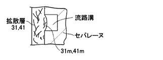
図4は、固体高分子型の燃料電池(単セル)の断面を模式的に示す。図4に示すように、上記した膜電極接合体50を炭素系の酸化剤用のセパレータ4(酸化剤用の配流部材),炭素系の燃料用のセパレータ5(燃料用の配流部材)で厚み方向に挟んで、固体高分子型の単セルの燃料電池が作製されている。セパレータ4には、酸化剤用のガス供給口4a、酸化剤用のガス通流のための凹状の流路溝4b、酸化剤用のガス排出口4cが設けられている。セパレータ5には、燃料用のガス供給口5a、燃料用のガス通流のための凹状の流路溝5b、燃料用のガス排出口5cが設けられている。発電運転時には、酸化剤用のガス供給口4aより酸化剤用の流路溝4bを介して酸化剤用の拡散層31に酸化剤用ガス(空気等の酸素含有ガス、反応流体)を供給し、且つ、燃料用のガス供給口5aより燃料用の流路溝5bを介して燃料用の拡散層41に燃料用ガス(水素含有ガスまたは水素ガス、反応流体)を供給する。
(Example 3)
FIG. 4 schematically shows a cross section of a solid polymer fuel cell (single cell). As shown in FIG. 4, the
本実施例においても、拡散層31,41(炭素繊維集積体)を構成する炭素繊維同士の接点が良好に繋がれ、拡散層31,41(炭素繊維集積体)の弾力性を良好に引き出すことができる。このため燃料電池の発電運転および運転停止等に起因して電解質膜20の膨張および収縮が発生するときであっても、電解質膜20の膨張および収縮に対する高い追従性を発揮する拡散層を形成することができる。図4は単セルに適用しているが、複数の単セルが厚み方向に積層されたスタックに適用できることは勿論である。
Also in the present embodiment, the contact points of the carbon fibers constituting the diffusion layers 31 and 41 (carbon fiber aggregates) are well connected, and the elasticity of the diffusion layers 31 and 41 (carbon fiber aggregates) is satisfactorily extracted. Can do. For this reason, even when the expansion and contraction of the
(実施例4)
本実施例は実施例1〜3と基本的には同様の構成であり、同様の作用効果を有するため、図1〜図4を準用することができる。実施例4に係る拡散層31,41は、実施例1と基本的には同様の手順で形成されている。但し、炭素繊維については、質量比でPAN系炭素繊維/ピッチ系炭素繊維=8.0/2.0とされている。直線性が高いPAN系炭素繊維の比率を増加することにより、拡散層31.41(炭素繊維集積体)の弾力性を高めるためである。
Example 4
Since the present embodiment has basically the same configuration as
(実施例5)
本実施例は実施例1〜3と基本的には同様の構成であり、同様の作用効果を有するため、図1〜図4を準用することができる。炭素繊維については、質量比でPAN系炭素繊維/ピッチ系炭素繊維=5.5/4.5とする。カール性が高いピッチ系炭素繊維の比率を増加することにより炭素繊維同士の絡み性を高めるためである。
(Example 5)
Since the present embodiment has basically the same configuration as
(実施例6)
図5は実施例6に係る燃料電池(単セル)の断面を模式的に示す。実施例6に係る拡散層31,41は、実施例1と基本的には同様の構成、作用効果を有する。図5に示すように、上記した膜電極接合体50を炭素系の酸化剤用のセパレータ4W(酸化剤用の配流部材),燃料用のセパレータ5W(燃料用の配流部材)で厚み方向に挟んで、固体高分子型の単セルの燃料電池が作製されている。セパレータ4Wは酸化剤ガスを流す流路溝の群を有せず、平坦な表面401をもつフラットタイプである。セパレータ5Wは燃料ガスを流す流路溝の群を有せず、平坦な表面501をもつフラットタイプである。図5に示すように、セパレータ4Wと拡散層31との間には、酸化剤用の多孔質体310が介在している。セパレータ5Wと拡散層41との間には、燃料用の多孔質体410が介在している。多孔質体310,410はシート状をなしており、多数の連続細孔を三次元的に有する反応流体透過性に富むものであり、例えば発泡金属等の発泡体で形成できる。発泡体としてはニッケル発泡体が例示される。
(Example 6)
FIG. 5 schematically shows a cross section of a fuel cell (unit cell) according to Example 6. The diffusion layers 31 and 41 according to the sixth embodiment have basically the same configuration and operational effects as the first embodiment. As shown in FIG. 5, the
ところで、上記したように拡散層31,41が高い弾力性を有するときには、流路溝の群を有するセパレータと共に組み込まれていると、セパレータ、膜電極接合体等を厚み方向に圧着させる圧着力が強くなると、図6に示すように、炭素繊維集積体で形成されている拡散層31,41の部分31m,41mがセパレータの流路溝内に膨出する度合が高くなる。この場合、流路溝の流路面積を小さくするおそれがあり、反応流体(燃料ガス、酸化剤ガス)の分配性が低下し、燃料電池の本来の発電性能が得られないおそれがある。この点本実施例によれば、拡散層31,41が高い弾力性を有するときであっても、流路溝なしのフラットタイプのセパレータ4W,5Wであれば、拡散層31,41の構成部分がセパレータの流路溝内に膨出することが軽減または回避され、ひいては流路溝の流路面積が小さくなるおそれが軽減または回避される。
By the way, as described above, when the diffusion layers 31 and 41 have high elasticity, if the diffusion layers 31 and 41 are incorporated together with a separator having a group of flow channel grooves, the crimping force for crimping the separator, the membrane electrode assembly, etc. in the thickness direction is increased. When it becomes stronger, as shown in FIG. 6, the degree to which the
(試験例)
上記した実施例1に基づいて製造した拡散層31について弾力性試験を実施する。弾力性試験では、拡散層31の試験片(36ミリメートル×36ミリメートル×厚み0.45ミリメートル)を用いて試験を実施する。この試験によれば、試験片(炭素繊維集積体)に厚み方向に所定の荷重(3MPa)を240秒間加えた。これは、膜電極接合体を作製する場合におけるプレス圧を想定したものである。その後、試験片を所定時間(10分間)放置する。
(Test example)
The elasticity test is performed on the
更に、試験片にこれの厚み方向に荷重を与えた。この場合、0.2MPaの荷重を試験片に厚み方向に加えた後、2.0MPaの荷重を試験片に加える操作を1往復とすると、往復30回、繰り返して荷重を試験片に加えた。これは、燃料電池の発電運転に基づく模擬荷重を想定したものであり、燃料電池の発電運転に基づく電解質膜の膨張および収縮を考慮したものである。なお、30回以降繰り返し荷重を印加したとしても、30回以降における試験片の厚みの変化はあまり認められなかった。 Further, a load was applied to the test piece in the thickness direction. In this case, after applying a 0.2 MPa load to the test piece in the thickness direction, and an operation of applying a 2.0 MPa load to the test piece as one reciprocation, the load was repeatedly applied to the test piece 30 times. This assumes a simulated load based on the power generation operation of the fuel cell, and takes into account the expansion and contraction of the electrolyte membrane based on the power generation operation of the fuel cell. In addition, even if it applied the load repeatedly after 30 times, the change of the thickness of the test piece after 30 times was not recognized so much.
次に、試験片の弾力性測定を行った。この場合、0.2MPaの荷重を試験片にこれの厚み方向に再び加えた後、0.6MPaの荷重を試験片にこれの厚み方向に再び加えた。そして、0.2MPaの荷重を加えた場合における試験片の厚みt0.2と、0.6MPaの荷重を加えた場合における試験片の厚みt0.6とを求めた。厚みt0.2と厚みt0.6との差を求めた。更に、次式に基づいて、試験片のヤング率(MPa)を求めた。ヤング率(MPa)=A/W
A=abs(0.2MPa−0.6MPa)
(ここでabsは絶対値を意味する。)
W=(t0.2−t0.6)/t0.2
比較例1〜比較例6についても同様な手順で試験片を形成し、弾力性を測定した。比較例1によれば、PAN系炭素繊維のみで形成されている。比較例2によれば、ピッチ系炭素繊維のみで形成されている。比較例1〜比較例6によれば、表1に示すように、平均分子量が100万〜1500とされている。
Next, the elasticity of the test piece was measured. In this case, a 0.2 MPa load was again applied to the test piece in the thickness direction, and then a 0.6 MPa load was applied to the test piece in the thickness direction again. Then, the thickness t 0.2 of the test piece when a load of 0.2 MPa was applied and the thickness t 0.6 of the test piece when a load of 0.6 MPa was applied were obtained. The difference between thickness t 0.2 and thickness t 0.6 was determined. Furthermore, the Young's modulus (MPa) of the test piece was obtained based on the following formula. Young's modulus (MPa) = A / W
A = abs (0.2 MPa-0.6 MPa)
(Here, abs means an absolute value.)
W = (t 0.2 -t 0.6 ) / t 0.2
For Comparative Examples 1 to 6, test pieces were formed in the same procedure, and the elasticity was measured. According to Comparative Example 1, it is formed of only PAN-based carbon fibers. According to the comparative example 2, it is formed only with pitch-based carbon fibers. According to Comparative Examples 1 to 6, as shown in Table 1, the average molecular weight is 1 million to 1500.

表1は試験結果を示す。弾力性の値(μm)は高いほうが好ましい。ヤング率(MPa)の値は低いほうが、弾力性有りとされる。試験片の弾力性を考慮すると、ヤング率(MPa)は5.5以下が好ましい。表1から理解できるように、比較例1によれば、PAN系炭素繊維のみで形成されているため、弾力性は充分ではない。比較例2によれば、ピッチ系炭素繊維のみで形成されているため、弾力性の値は充分ではない。比較例3,4によれば、PAN系炭素繊維およびピッチ系炭素繊維が混在しているものの、撥水材の分子量が適切ではないため、弾力性の値は充分ではなく、更に、ヤング率も5.6以上と高く、あまり良好でなかった。 Table 1 shows the test results. A higher elasticity value (μm) is preferable. The lower the Young's modulus (MPa) value, the more elastic. Considering the elasticity of the test piece, the Young's modulus (MPa) is preferably 5.5 or less. As can be understood from Table 1, according to Comparative Example 1, since it is formed of only PAN-based carbon fibers, its elasticity is not sufficient. According to the comparative example 2, since it is formed only with pitch-based carbon fibers, the value of elasticity is not sufficient. According to Comparative Examples 3 and 4, although the PAN-based carbon fiber and the pitch-based carbon fiber are mixed, since the molecular weight of the water repellent material is not appropriate, the elasticity value is not sufficient, and the Young's modulus is also high. It was as high as 5.6 or higher and was not very good.
これに対して、撥水材(PTFE)の平均分子量が100万以下に設定されている試験例1〜試験例6(発明品)によれば、弾力性の値が16以上であり良好であり、ヤング率も抑えられていた。殊に、試験例1〜試験例5によれば、撥水材(PTFE)の平均分子量が50万と低めに設定されているため、弾力性の値が16以上であり良好であり、ヤング率も抑えられていた。 On the other hand, according to Test Example 1 to Test Example 6 (invention product) in which the average molecular weight of the water repellent material (PTFE) is set to 1 million or less, the elasticity value is 16 or more, which is favorable. The Young's modulus was also suppressed. In particular, according to Test Examples 1 to 5, since the average molecular weight of the water repellent material (PTFE) is set to a low value of 500,000, the elasticity value is 16 or more, and the Young's modulus is good. Was also suppressed.
更に試験例2〜試験例4によれば、撥水材(PTFE)の平均分子量が50万と低めに設定されていると共に、炭素繊維/撥水材の固形分の比率が1.45〜2.76の範囲内に設定されているため、弾力性の値が20.0であり、極めて良好であった。 Furthermore, according to Test Example 2 to Test Example 4, the average molecular weight of the water repellent material (PTFE) is set as low as 500,000, and the solid content ratio of the carbon fiber / water repellent material is 1.45 to 2. Since it was set within the range of .76, the elasticity value was 20.0, which was very good.
このように弾力性を良好にするためには、質量比で炭素繊維/撥水材の固形分の比率が1.20〜3.00の範囲内、殊に1.40〜2.80の範囲内が良好であることがわかる。比較例1〜比較例6によれば、炭素繊維/撥水材の固形分の比率が適切であったとしても、充分な弾力性が得られない。ここで、この比率において、炭素繊維はPAN系炭素繊維およびピッチ系炭素繊維の合計をいう。 In order to improve the elasticity in this way, the ratio of carbon fiber / water repellent solid content in the mass ratio is in the range of 1.20 to 3.00, particularly in the range of 1.40 to 2.80. It can be seen that the inside is good. According to Comparative Examples 1 to 6, even if the solid ratio of carbon fiber / water repellent material is appropriate, sufficient elasticity cannot be obtained. Here, in this ratio, the carbon fiber refers to the total of the PAN-based carbon fiber and the pitch-based carbon fiber.
(その他)
上記した実施形態1によれば、PAN系炭素繊維およびピッチ系炭素繊維の平均繊維長および平均繊維径については、上記した値に限定されるものではなく、拡散層に要請される性質に応じて、適宜変更できることは勿論である。例えば、PAN系炭素繊維については、平均繊維長が1〜12ミリメートル、平均繊維径が7〜15μmを例示することができる。ピッチ系炭素繊維については、平均繊維長が1〜12ミリメートル、平均繊維径が7〜15μmを例示することができる。上記した実施形態1によれば、抄紙の際に、質量比で、炭素繊維/パルプの比率は6/4相当とされているが、抄紙条件、燃料電池の発電条件によって適宜設定されるものであり、これに限らず、7/3相当、8/2相当、5/5相当、4/6相当としても良い。上記した実施形態1によれば、撥水材としてPTFEが採用されているが、平均分子量(数平均分子量)が100万以下であれば、FEP、PFAとしても良い。
(Other)
According to
上記した実施例1によれば、第1流動物の目付け量を第2流動物の目付け量よりも大きく設定しているが、これに限らず、第1流動物の目付け量を第2流動物の目付け量よりも小さく設定しても良い場合もある。この場合、集積シート100を構成する炭素繊維を保持するバインダ機能を第1,第2流動物にもたせつつ、反応ガス透過性、排水性を調整するためである。このように要請に応じて、第1流動物の目付け量と第2流動物の目付け量と比率を調整できる。その他、本発明は上記した実施形態のみに限定されるものではなく、要旨を逸脱しない範囲内で適宜変更して実施できる。
According to Example 1 described above, the basis weight of the first fluid is set to be larger than the basis weight of the second fluid, but not limited to this, the basis weight of the first fluid is set to the second fluid. In some cases, it may be set smaller than the basis weight. In this case, it is for adjusting reactive gas permeability and drainage, making the 1st and 2nd fluids have the binder function which holds the carbon fiber which constitutes
本発明は固体高分子型等の燃料電池に利用できる。 The present invention can be used for solid polymer type fuel cells.
100は集積シート(炭素繊維集積体)、50は膜電極接合体、41は燃料用の拡散層、18は燃料用の触媒層、20は電解質膜、14は酸化剤用の触媒層、31は酸化剤用の拡散層、4は酸化剤用のセパレータ(酸化剤用の配流部材),5は燃料用のセパレータ(燃料用の配流部材)、4Wは酸化剤用のセパレータ(酸化剤用の配流部材),5Wは燃料用のセパレータ(燃料用の配流部材)、310は多孔質体、410多孔質体を示す。 100 is an accumulation sheet (carbon fiber assembly), 50 is a membrane electrode assembly, 41 is a diffusion layer for fuel, 18 is a catalyst layer for fuel, 20 is an electrolyte membrane, 14 is a catalyst layer for oxidant, and 31 is Diffusion layer for oxidant, 4 is a separator for oxidant (distribution member for oxidant), 5 is a separator for fuel (distribution member for fuel), 4W is a separator for oxidant (distribution for oxidant) Member), 5W is a separator for fuel (distribution member for fuel), 310 is a porous body, and 410 is a porous body.
Claims (6)
多数の炭素繊維が互いに絡み合っている炭素繊維集積体と、前記炭素繊維間に含浸されると共に炭素繊維結合性をもち且つ平均分子量が100万以下の撥水材とを具備することを特徴とする燃料電池用拡散層。 A diffusion layer for a fuel cell that diffuses a reaction fluid used for a power generation reaction of a fuel cell,
A carbon fiber assembly in which a large number of carbon fibers are entangled with each other, and a water repellent material impregnated between the carbon fibers and having carbon fiber binding properties and an average molecular weight of 1,000,000 or less. Diffusion layer for fuel cells.
多数の炭素繊維が互いに絡みあった炭素繊維集積体を準備すると共に、炭素繊維結合性をもつ平均分子量が100万以下の撥水材を含む第1流動物を準備する工程と、
前記炭素繊維集積体にこれの表面から前記第1流動物を含浸させて拡散中間層を形成する含浸工程と、
前記拡散中間層を焼成温度に加熱して前記炭素繊維同士を前記撥水材で結合する加熱工程とを含むことを特徴とする燃料電池用拡散層の製造方法。 A method for producing a diffusion layer for a fuel cell in which a reaction fluid used for a power generation reaction of a fuel cell is diffused,
Preparing a carbon fiber aggregate in which a large number of carbon fibers are entangled with each other, and preparing a first fluid containing a water-repellent material having an average molecular weight of 1 million or less having carbon fiber binding properties;
An impregnation step of impregnating the first fluid from the surface of the carbon fiber aggregate to form a diffusion intermediate layer;
And a heating step of heating the diffusion intermediate layer to a firing temperature and bonding the carbon fibers together with the water repellent material.
前記膜電極接合体のうち前記燃料用拡散層に対面すると共に前記燃料用拡散層に燃料を供給する燃料用配流部材と、前記膜電極接合体のうち前記酸化剤用拡散層に対面すると共に前記酸化剤用拡散層に酸化剤を供給する酸化剤用配流部材とを具備する燃料電池において、
前記燃料用拡散層および前記酸化剤用拡散層のうちの少なくとも一方は、請求項1〜3のうちの一項に係る燃料電池用拡散層で構成されていることを特徴とする燃料電池。 A membrane electrode assembly in which a fuel diffusion layer, a fuel catalyst layer, an electrolyte membrane, an oxidant catalyst layer, and an oxidant diffusion layer are sequentially laminated;
A fuel distribution member that faces the fuel diffusion layer in the membrane electrode assembly and supplies fuel to the fuel diffusion layer, and faces the oxidant diffusion layer in the membrane electrode assembly and In a fuel cell comprising an oxidant distribution member for supplying an oxidant to an oxidant diffusion layer,
At least one of the said fuel diffusion layer and the said oxidizing agent diffusion layer is comprised by the diffusion layer for fuel cells which concerns on one of Claims 1-3, The fuel cell characterized by the above-mentioned.
Priority Applications (1)
| Application Number | Priority Date | Filing Date | Title |
|---|---|---|---|
| JP2007253516A JP2009087616A (en) | 2007-09-28 | 2007-09-28 | Diffusion layer of fuel cell, manufacturing method for diffusion layer of fuel cell, and fuel cell |
Applications Claiming Priority (1)
| Application Number | Priority Date | Filing Date | Title |
|---|---|---|---|
| JP2007253516A JP2009087616A (en) | 2007-09-28 | 2007-09-28 | Diffusion layer of fuel cell, manufacturing method for diffusion layer of fuel cell, and fuel cell |
Publications (1)
| Publication Number | Publication Date |
|---|---|
| JP2009087616A true JP2009087616A (en) | 2009-04-23 |
Family
ID=40660799
Family Applications (1)
| Application Number | Title | Priority Date | Filing Date |
|---|---|---|---|
| JP2007253516A Pending JP2009087616A (en) | 2007-09-28 | 2007-09-28 | Diffusion layer of fuel cell, manufacturing method for diffusion layer of fuel cell, and fuel cell |
Country Status (1)
| Country | Link |
|---|---|
| JP (1) | JP2009087616A (en) |
Cited By (2)
| Publication number | Priority date | Publication date | Assignee | Title |
|---|---|---|---|---|
| WO2011065349A1 (en) * | 2009-11-24 | 2011-06-03 | 三菱レイヨン株式会社 | Porous electrode base material and process for production thereof |
| WO2014007397A1 (en) * | 2012-07-06 | 2014-01-09 | ダイキン工業株式会社 | Sheet, electrode and fuel cell |
-
2007
- 2007-09-28 JP JP2007253516A patent/JP2009087616A/en active Pending
Cited By (5)
| Publication number | Priority date | Publication date | Assignee | Title |
|---|---|---|---|---|
| WO2011065349A1 (en) * | 2009-11-24 | 2011-06-03 | 三菱レイヨン株式会社 | Porous electrode base material and process for production thereof |
| JP5433588B2 (en) * | 2009-11-24 | 2014-03-05 | 三菱レイヨン株式会社 | Porous electrode substrate and method for producing the same |
| WO2014007397A1 (en) * | 2012-07-06 | 2014-01-09 | ダイキン工業株式会社 | Sheet, electrode and fuel cell |
| JP2014112514A (en) * | 2012-07-06 | 2014-06-19 | Daikin Ind Ltd | Sheet, electrode and fuel cell |
| CN104412433A (en) * | 2012-07-06 | 2015-03-11 | 大金工业株式会社 | Sheet, electrode and fuel cell |
Similar Documents
| Publication | Publication Date | Title |
|---|---|---|
| KR101484762B1 (en) | Carbon substrate for gas diffusion layer, gas diffusion layer using the same, and electrode for fuel cell comprising the gas diffusion layer | |
| JP4930644B1 (en) | Gas diffusion layer for fuel cell and manufacturing method thereof | |
| JP6717748B2 (en) | Gas diffusion base material | |
| JP5066998B2 (en) | Membrane electrode assembly for polymer electrolyte fuel cells | |
| JP6086164B2 (en) | Porous electrode substrate, membrane-electrode assembly using the same, and polymer electrolyte fuel cell using the same | |
| JPWO2007052650A1 (en) | Manufacturing method of membrane electrode assembly for polymer electrolyte fuel cell | |
| TWI644477B (en) | Gas diffusion electrode substrate, membrane electrode assembly having the same, and fuel cell | |
| JP5482066B2 (en) | Microporous layer for fuel cell, gas diffusion electrode with microporous layer, catalyst layer with microporous layer, gas diffusion electrode with catalyst layer and membrane-electrode assembly, and polymer electrolyte fuel cell | |
| KR101747456B1 (en) | Gas diffusion layer member for solid polymer fuel cells, and solid polymer fuel cell | |
| KR102334668B1 (en) | Carbon sheet, gas diffusion electrode base material, and fuel cell | |
| JP5987484B2 (en) | Gas diffusion electrode substrate and method for producing the same | |
| TWI692143B (en) | Carbon flake, gas diffusion electrode base material and fuel cell | |
| TWI648162B (en) | Gas diffusion electrode substrate, membrane electrode assembly having the same, and fuel cell | |
| JP2010146965A (en) | Membrane-electrode assembly for solid polymer fuel cell, coating liquid for forming catalyst layer of solid polymer fuel cell, and manufacturing method for membrane-electrode assembly of solid polymer fuel cell | |
| KR20170081197A (en) | Gas diffusion electrode base and method for producing gas diffusion electrode base | |
| KR20170069243A (en) | Carbon sheet, gas diffusion electrode base material, and fuel cell | |
| KR20160125366A (en) | Gas diffusion electrode substrate | |
| JP6205718B2 (en) | Fuel cell gas diffusion layer, membrane electrode assembly, and fuel cell | |
| JP2009087614A (en) | Diffusion layer of fuel cell, manufacturing method for diffusion layer of fuel cell, and fuel cell | |
| JP6988788B2 (en) | Gas diffusion electrode and its manufacturing method | |
| JP2008210725A (en) | Gas diffusion electrode, membrane-electrode assembly and its manufacturing method, and solid polymer fuel cell | |
| JP2009087616A (en) | Diffusion layer of fuel cell, manufacturing method for diffusion layer of fuel cell, and fuel cell | |
| JP4993024B1 (en) | Membrane-electrode assembly for fuel cell, method for producing the same, and polymer electrolyte fuel cell using the membrane-electrode assembly | |
| KR20190103175A (en) | Gas Diffusion Electrodes and Fuel Cells | |
| KR20180053680A (en) | Gas diffusion electrode and manufacturing method thereof |