JP2009080147A - Image forming apparatus - Google Patents
Image forming apparatus Download PDFInfo
- Publication number
- JP2009080147A JP2009080147A JP2007247022A JP2007247022A JP2009080147A JP 2009080147 A JP2009080147 A JP 2009080147A JP 2007247022 A JP2007247022 A JP 2007247022A JP 2007247022 A JP2007247022 A JP 2007247022A JP 2009080147 A JP2009080147 A JP 2009080147A
- Authority
- JP
- Japan
- Prior art keywords
- image forming
- forming apparatus
- cover
- exposure
- holding
- Prior art date
- Legal status (The legal status is an assumption and is not a legal conclusion. Google has not performed a legal analysis and makes no representation as to the accuracy of the status listed.)
- Withdrawn
Links
- 238000012423 maintenance Methods 0.000 abstract description 4
- 238000004140 cleaning Methods 0.000 abstract 1
- 238000012546 transfer Methods 0.000 description 17
- 238000000034 method Methods 0.000 description 13
- 230000008569 process Effects 0.000 description 9
- 238000010586 diagram Methods 0.000 description 8
- 230000007246 mechanism Effects 0.000 description 8
- 238000001514 detection method Methods 0.000 description 3
- 238000011161 development Methods 0.000 description 2
- 238000007689 inspection Methods 0.000 description 2
- 230000008859 change Effects 0.000 description 1
- 239000004020 conductor Substances 0.000 description 1
- 238000007599 discharging Methods 0.000 description 1
- 230000000694 effects Effects 0.000 description 1
- 230000001678 irradiating effect Effects 0.000 description 1
- 239000000463 material Substances 0.000 description 1
- 238000012986 modification Methods 0.000 description 1
- 230000004048 modification Effects 0.000 description 1
Images


Abstract
Description
本発明は、画像形成装置に関するものである。 The present invention relates to an image forming apparatus.
従来、電子写真プロセスを利用するプリンタ、複写機、ファクシミリ機等の画像形成装置においては、感光体ドラムに電荷を蓄える帯電プロセス、画像データの存在する位置に光を照射する露光プロセス、露光された部分にトナー像を付着させる現像プロセス、現像されたトナーを印刷媒体に転写させる転写プロセス、印刷媒体上に載っているトナー像を熱及び圧力で定着させる定着プロセスの順で行われる電子写真プロセスによって、紙等の印刷媒体上に画像を形成するようになっている。 Conventionally, in an image forming apparatus such as a printer, a copier, or a facsimile machine using an electrophotographic process, a charging process for storing charges on a photosensitive drum, an exposure process for irradiating light on a position where image data exists, and exposure By an electrophotographic process performed in the order of a development process for attaching a toner image to a part, a transfer process for transferring the developed toner to a printing medium, and a fixing process for fixing the toner image on the printing medium with heat and pressure An image is formed on a print medium such as paper.
このような構成の画像形成装置においては、装置本体の上カバーが回動自在に支持されるメカフレームの内部に、感光体ドラムとしてのOPC(有機光導電体:Organic Photo Conductor)ドラムを具備したトナー像形成部を配設したタイプのものが存在する。この場合、メカフレームの後方の側面板の内側に形成された回動支軸が、上カバーの後方に設けた回動支軸穴に挿入される。このように、上カバーは、メカフレームに回動自在に軸支されることによって、メカフレームの開口部分を覆うように取り付けられている。 In the image forming apparatus having such a configuration, an OPC (Organic Photo Conductor) drum as a photosensitive drum is provided inside a mechanical frame in which the upper cover of the apparatus main body is rotatably supported. There is a type in which a toner image forming unit is provided. In this case, the rotation support shaft formed inside the side plate behind the mechanical frame is inserted into a rotation support shaft hole provided behind the upper cover. Thus, the upper cover is attached so as to cover the opening of the mechanical frame by being pivotally supported by the mechanical frame.
また、上カバーの前方内側には、印字ヘッド保持部材が設けられていて、該印字ヘッド保持カバーの先端部分に、LED(Light Emitting Diode)アレイ等の光源を備える印字ヘッドが遊動自在に保持されている。該印字ヘッドは、上カバーを開閉する際の円弧運動によってトナー像形成部と合体するようになっている(例えば、特許文献1参照。)。
しかしながら、前記従来の画像形成装置においては、上カバーの上にスキャナのような重量物が積載されてしまうと、上カバーとともに重量物を同時に開閉しなければならないので、上カバーの回動部を重量物の重量に耐え得る強固なものにしなければならず、装置本体が大型化するという問題が生じてしまう。 However, in the conventional image forming apparatus, if a heavy object such as a scanner is loaded on the upper cover, the heavy object must be opened and closed simultaneously with the upper cover. It must be strong enough to withstand the weight of a heavy object, resulting in a problem that the apparatus main body becomes large.
本発明は、前記従来の画像形成装置の問題点を解決して、露光部を保持する保持部が装置本体の側面に位置するように前記保持部を支持するカバー部を配設し、該カバー部の開動作に伴って前記保持部が所定角度傾斜し、前記カバー部を開放すると前記露光部が上方を向くようにすることによって、露光部の保守点検のために装置本体の上部を開ける必要がないので操作性が向上し、カバー部を開放したときに露光部の視認性が高く、清掃を容易に行うことができる画像形成装置を提供することを目的とする。 The present invention solves the problems of the conventional image forming apparatus, and disposes a cover portion that supports the holding portion so that the holding portion that holds the exposure portion is positioned on the side surface of the apparatus body. It is necessary to open the upper part of the apparatus main body for maintenance inspection of the exposure unit by tilting the holding unit by a predetermined angle with the opening operation of the unit and opening the cover unit so that the exposure unit faces upward Therefore, an object of the present invention is to provide an image forming apparatus that improves operability, has high visibility of the exposed portion when the cover portion is opened, and can be easily cleaned.
そのために、本発明の画像形成装置においては、像担持体に静電潜像を形成する露光部と、該露光部を保持する保持部と、開閉可能であって、閉止したときに前記保持部が装置本体の側面に位置するように前記保持部を支持するカバー部とを有し、該カバー部の前記保持部を支持する面は、前記カバー部を開放したときに上方を向く。 Therefore, in the image forming apparatus of the present invention, the exposure unit that forms an electrostatic latent image on the image carrier, the holding unit that holds the exposure unit, and the opening and closing unit that can be opened and closed. Has a cover portion that supports the holding portion so that the holding portion is positioned on a side surface of the apparatus main body, and a surface of the cover portion that supports the holding portion faces upward when the cover portion is opened.
本発明の他の画像形成装置においては、像担持体に静電潜像を形成する露光部と、該露光部を保持する保持部と、開閉可能であって、閉止したときに前記保持部が装置本体の側面に位置するように前記保持部を支持するカバー部とを有し、該カバー部は、前記露光部の長手方向に対して直交する回転軸を中心に回転して開閉する。 In another image forming apparatus of the present invention, an exposure unit that forms an electrostatic latent image on an image carrier, a holding unit that holds the exposure unit, and an opening and closing unit that can be opened and closed. And a cover portion that supports the holding portion so as to be positioned on a side surface of the apparatus main body, and the cover portion opens and closes by rotating about a rotation axis orthogonal to the longitudinal direction of the exposure portion.
本発明によれば、画像形成装置においては、装置本体の上部を開ける必要がないので操作性が向上し、カバー部を開放したときに露光部の視認性が高く、清掃を容易に行うことができる。 According to the present invention, in the image forming apparatus, it is not necessary to open the upper part of the apparatus main body, so that the operability is improved, and when the cover part is opened, the exposure part is highly visible and can be easily cleaned. it can.
以下、本発明の実施の形態について図面を参照しながら詳細に説明する。 Hereinafter, embodiments of the present invention will be described in detail with reference to the drawings.
図1は本発明の第1の実施の形態における画像形成装置の構成を示す図、図2は本発明の第1の実施の形態におけるヘッド保持部材及びリンク部材を画像形成装置の右側面から観た図である。 FIG. 1 is a diagram showing the configuration of the image forming apparatus according to the first embodiment of the present invention, and FIG. 2 is a view of the head holding member and the link member according to the first embodiment of the present invention from the right side of the image forming apparatus. It is a figure.
図1において、10は画像形成装置であり、例えば、プリンタ、ファクシミリ機、複写機、プリンタ、ファクシミリ機及び複写機の機能を併せ持つ複合機(MFP:Multifunction Printer)等であるが、いかなる種類のものであってもよい。本実施の形態において、前記画像形成装置10は、電子写真方式によって画像を形成するものであり、内部には、画像形成部30及び定着部50が媒体11の搬送経路に沿って配設されている。そして、前記画像形成部30において電子写真方式の現像プロセスが行われて媒体11上にトナー像が形成され、定着部50において定着プロセスが行われてトナー像が媒体11上に定着される。なお、画像形成装置10は、カラー画像を形成する装置であってもよいし、モノクロ電子写真式プリンタのように白黒画像を形成する装置であってもよいが、本実施の形態においては、前記画像形成装置10がいわゆるタンデム方式のカラー電子写真式プリンタである場合について説明する。
In FIG. 1,
そして、画像形成装置10の下部には着脱可能な給紙部12が配設される。該給紙部12は、給紙トレイ13、押し上げ板14及びホッピングローラ15を有する。この場合、給紙トレイ13内に収納された媒体11は、押し上げ板14を介して図示されない押圧手段からの押圧力を受け、ホッピングローラ15に圧接させられる。そして、前記媒体11がホッピングローラ15に圧接させられている状態で、図示されないモータによってホッピングローラ15を回転させると、前記給紙トレイ13の内部に積層された媒体11は、上から順次繰り出される。繰り出された媒体11は、フィードローラ21及びリタードローラ22を備える媒体繰り出し部20によって1枚ずつに分離されて搬送される。なお、前記給紙部12には、媒体11の上昇を検知する上昇検知センサ、媒体11の有無を検知する媒体有無検知センサ、媒体11の残量を検知する媒体残量検知センサ等のセンサ16〜18が配設される。
A detachable
さらに、前記媒体11は、レジストローラ対23に送り込まれて斜行を矯正された後、媒体11への画像書き出しセンサ24を通過して2次転写ローラ46へと搬送される。そして、該2次転写ローラ46で媒体11に転写されるトナー像は、画像形成部30で形成される。
Further, the
ここで、該画像形成部30について説明する。
Here, the
該画像形成部30は、直列に並べられた4つのトナー像形成部31と、該トナー像形成部31によって形成されたトナー像を媒体11上面に転写する転写部41とから成る。そして、前記トナー像形成部31には、トナー像を担持する像担持体としてのOPCドラム32、該OPCドラム32の表面を帯電させるための帯電部としての帯電ローラ33、帯電したOPCドラム32の表面に静電潜像を形成するLEDアレイから成る露光部34、摩擦帯電によって静電潜像を現像してトナー像を形成する現像ローラ35、及び、該現像ローラ35にトナーを供給するトナー供給部36が配設される。
The
また、前記転写部41は、媒体11を静電吸着して搬送する中間転写ベルト42、図示されない駆動部によって回転され、前記中間転写ベルト42を駆動するドライブローラ43、前記中間転写ベルト42を張架するテンションローラ44、前記トナー像形成部31に対向し、OPCドラム32に圧接するように配置されトナー像を中間転写ベルト42上に転写するように電圧を印加する転写ローラ45、及び、中間転写ベルト42上のトナー像を媒体11に転写するように電圧を印加する2次転写ローラ46を有する。
Further, the
そして、前記画像形成部30でトナー像を転写された媒体11は、定着部50に送り込まれる。該定着部50において、トナー像が媒体11に熱と圧力で融着される。その後、媒体11は、該媒体11を装置本体の外部に排出するための排出ローラ対51によって、装置本体の上部に位置するスタッカ部52へ排出される。
Then, the
なお、画像形成装置10は、メカフレーム70で保持され、カバー部によって保護されている。該カバー部は、スタッカ部52が設けられ装置本体の天面を覆うスタッカカバー61、左側面を覆う左サイドカバー62、右側面を覆う右サイドカバー81、図示されない背面を覆うリヤカバー、及び、正面を覆うフロントカバーによって構成される。本実施の形態においては、図1を正面とし、媒体11を搬送する面を左側面として説明する。
The
前記メカフレーム70には、右サイドカバー81の下方の内側に形成された回動支軸71が取り付けられている。該回動支軸71は、右サイドカバー81の下方に配設された回動支軸穴に挿入され、これにより、右サイドカバー81は、メカフレーム70に回動自在に軸支され、メカフレーム70の右開口部分を覆うように取り付けられている。そして、右サイドカバー81には、LEDアレイから成る露光部34を保持する保持部としてのヘッド保持部材82を軸支するための回動支軸83と、リンク部材86及び87を軸支するための回動支軸84とが配設されている。前記ヘッド保持部材82の先端部分には、露光部34が遊動自在に保持されている。
A
ここで、画像形成装置10は、タンデム方式のカラー電子写真式プリンタであるので、露光部34及びヘッド保持部材82を4セット備えている。本実施の形態では、4セットのヘッド保持部材82の各々を、下方から、ヘッド保持部材82a、ヘッド保持部材82b、ヘッド保持部材82c及びヘッド保持部材82dとして説明する。
Here, since the
また、メカフレーム70は、ヘッド保持部材82aとリンク部材86とを回動自在に保持する回動支軸85を有する。該回動支軸85は、リンク部材86に配設された回動支軸穴に挿入されている。つまり、リンク部材86は、メカフレーム70とヘッド保持部材82aとをつないでいる。そして、図2に示されるように、リンク部材87の両端部には回動支持軸穴が形成されており、該回動支持軸穴に、ヘッド保持部材82a、82b、82c及び82dに配設された回動支軸84がそれぞれ挿入されている。
Further, the
次に、前記構成の画像形成装置10の右サイドカバー81の開閉動作について説明する。
Next, an opening / closing operation of the
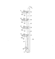
図3は本発明の第1の実施の形態における右サイドカバーが画像形成装置内に収納されている状態を示す図、図4は本発明の第1の実施の形態における右サイドカバーの開閉動作内の一部の状態を示す図、図5は本発明の第1の実施の形態における右サイドカバーが完全に開いた状態を示す図、図6は本発明の第1の実施の形態における右サイドカバーが完全に開いた状態の画像形成装置を示す図、図7は本発明の第1の実施の形態における右サイドカバーが完全に開いた状態の画像形成装置の斜視図である。 FIG. 3 is a diagram illustrating a state in which the right side cover according to the first embodiment of the present invention is housed in the image forming apparatus, and FIG. 4 is an opening / closing operation of the right side cover according to the first embodiment of the present invention. FIG. 5 is a view showing a state in which the right side cover is completely opened in the first embodiment of the present invention, and FIG. 6 is a right view in the first embodiment of the present invention. FIG. 7 is a perspective view of the image forming apparatus in a state in which the right side cover is completely opened in the first embodiment of the present invention.
右サイドカバー81を開くとき、図3において、右サイドカバー81は、回動支軸71を支軸とし、矢印Aで示されるように、右側へ傾倒していく。このとき、リンク部材86に連結されたヘッド保持部材82aは、リンク部材86とメカフレーム70とに設けられた回動支軸85、及び、ヘッド保持部材82aの回動支軸83を固定軸とし、ヘッド保持部材82aとリンク部材86との回動支軸84を揺動軸として、矢印cで示される方向へ傾倒する。同様に、リンク部材87によって連結されたヘッド保持部材82b、82c及び82dは、各ヘッド保持部材82とリンク部材87との回動支軸84を揺動軸として、矢印cで示される方向に傾倒する。
When the
右サイドカバー81を傾倒し続けることで、図4に示される状態を経て、最終的に、図5に示されるように、右サイドカバー81が開いた状態では、リンク機構によって、各ヘッド保持部材82は所定の角度αだけ傾倒する。本実施の形態においては、傾倒する角度αは、好ましくは、45度であるものとするが、この限りではなく、露光部34が外側を向き、かつ、露光部34同士が互いに重ならないような角度であれば、任意に設定することができる。
By continuing to tilt the
なお、図6及び7には、右サイドカバー81が完全に開いた画像形成装置10の状態が示されている。この状態からも明らかなように、右サイドカバー81が開いた状態では、露光部34が剥(む)き出しになり、かつ、トナー像形成部31も剥き出しとなる。
6 and 7 show the state of the
このように、本実施の形態においては、右サイドカバー81に露光部34を実装したので、トナー像形成部31の保守点検等のためには、右サイドカバー81を開閉すればよく、装置本体の天面を覆い、開閉操作が困難なスタッカカバー61を開閉する必要がなくなったので、操作性が向上した。
Thus, in the present embodiment, since the
また、スタッカカバー61が開閉されないので、MFP化などの際に、オプション機器類を装置本体上に配置することが可能となる。この場合、スタッカカバー61を開閉する必要がないので、オプション機器類のような重量物とともにスタッカカバー61を開閉するための部材を削減することができる。
Further, since the
さらに、右サイドカバー81が開いた状態では、露光部34が上方を向いて剥き出しになるために、該露光部34の視認性が非常によく、露光部34の清掃も容易に行うことができる。
Further, in a state where the
さらに、右サイドカバー81の開閉動作に連動して、LEDアレイから成る露光部34が所定角度外側に傾倒する、すなわち、鉛直方向に対して傾斜するので、万が一、開いた状態の右サイドカバー81上に異物を落としてしまうことがあっても、露光部34の面が真上を向いていないために、露光部34の面の破損、キズ等の発生が防止される。
Further, in conjunction with the opening / closing operation of the
次に、本発明の第2の実施の形態について説明する。なお、第1の実施の形態と同じ構成を有するものについては、同じ符号を付与することにより、その説明を省略する。また、前記第1の実施の形態と同じ動作及び同じ効果についても、その説明を省略する。 Next, a second embodiment of the present invention will be described. In addition, about what has the same structure as 1st Embodiment, the description is abbreviate | omitted by providing the same code | symbol. The description of the same operation and the same effect as those of the first embodiment is also omitted.
図8は本発明の第2の実施の形態における画像形成装置を正面方向から観た構成図、図9は本発明の第2の実施の形態における画像形成装置を上方から観た構成図、図10は本発明の第2の実施の形態における露光部の可動機構を示す斜視図であり右サイドカバーが閉のときの状態を示す図である。 FIG. 8 is a structural view of the image forming apparatus according to the second embodiment of the present invention as viewed from the front, and FIG. 9 is a structural view of the image forming apparatus according to the second embodiment of the present invention as viewed from above. 10 is a perspective view showing a movable mechanism of the exposure unit in the second embodiment of the present invention, and shows a state when the right side cover is closed. FIG.
本実施の形態において、右サイドカバー81は、その回転軸が露光部34の長手方向に対して直交するように取り付けられ、メカフレーム70の右開口部分を覆うようになっている。そのため、右サイドカバー81の回転軸が鉛直方向に延在するように形成された回動支軸91がメカフレーム70に取り付けられている。前記回転支軸91は、右サイドカバー81の露光部34の長手方向に対して形成された回動支軸穴に挿入され、これにより、サイドカバー81は、メカフレーム70に回動自在に軸支される。図9に示されるように、右サイドカバー81は、回動支軸91を回転軸として回転し、開閉方向dで示されるように開閉する。
In the present embodiment, the
また、回動支軸91には、図10に示されるように、露光部34を可動させる機構が配設されている。回動支軸91には扇型ギヤ92が回転自在に配設されており、該扇型ギヤ92に噛(か)み合うアイドルギヤ93、及び、該アイドルギヤ93とともに回転する回転軸94が配設される。同様に、アイドルギヤ93とともに回転し、回転を直交方向に変えるベベルギヤ95及び96、該ベベルギヤ96に形成される平歯ギヤに噛み合うギヤ97のギヤ列が形成される。ギヤ97は、ヘッド保持部材82が回転可能なように、嵌(かん)合されている。
Further, as shown in FIG. 10, the
次に、本実施の形態における画像形成装置10の右サイドカバー81の動作について説明する。
Next, the operation of the
図11は本発明の第2の実施の形態における露光部の可動機構を示す斜視図であり右サイドカバーが開のときの状態を示す図、図12は本発明の第2の実施の形態における露光部の可動機構を示す正面図であり露光部の傾きを示す図である。 FIG. 11 is a perspective view showing the movable mechanism of the exposure unit in the second embodiment of the present invention, showing the state when the right side cover is open, and FIG. 12 in the second embodiment of the present invention. It is a front view which shows the movable mechanism of an exposure part, and is a figure which shows the inclination of an exposure part.
図10に示されるように、右サイドカバー81が閉じている状態では、露光部34は水平方向に保持されている。そして、右サイドカバー81を開き始めると、扇型ギヤ92が矢印eで示される方向に回転を始める。すると、アイドルギヤ93、回転軸94及びベベルギヤ95が回転し、該ベベルギヤ95及び96によって回転方向が直角に変換され、ギヤ97に伝達される。該ギヤ97は、ヘッド保持部材82に固定されているので、これにより、ヘッド保持部材82が回動支軸91を中心に回動する。
As shown in FIG. 10, when the
そして、右サイドカバー81が完全に開いた状態になると、図11に示されるように、ヘッド保持部材82は斜め下方を向くようにする。図12は、ヘッド保持部材82を正面から観た図であり、ヘッド保持部材82が所定の角度βだけ下向きに傾倒していることを示している。本実施の形態においては、傾倒する角度βは、好ましくは、30度であるものとするが、この限りではなく、露光部34が斜め下方を向き、かつ、該露光部34同士が互いに重ならないような角度であれば、任意に設定することができる。
When the
このように、本実施の形態において、右サイドカバー81は、回転支軸91が露光部34の長手方向に対し直交する方向に保持される。これにより、前記第1の実施の形態に対して開閉における開閉半径をより小さくすることができるため、消耗品交換時における保守スペースを狭くすることが可能となる。また、右サイドカバー81を開いたときの占有面積も狭くすることが可能となる。
Thus, in the present embodiment, the
さらに、右サイドカバー81が開いた状態では、露光部34が剥き出しになり、かつ、正面を向いた状態となるので、露光部34の視認性が更によくなり、露光部34の清掃も容易に行うことができる。また、右サイドカバー81の開閉動作に連動して、露光部34が所定角度下側に傾倒するので、万が一、開いた状態の右サイドカバー81上に異物を落としてしまうことがあっても、露光部34の面が真上を向いていないために、露光部34の面の破損、キズ等の発生が防止される。
Further, when the
なお、前記第1及び第2の実施の形態においては、電子写真式プリンタに適用した例を述べたが、電子写真式を利用して記録材上に画像を形成する複写機、ファクシミリ機、プリンタ等の画像形成装置に利用可能である。また、電子写真式として、中間転写方式を適用した例について述べたが、直接転写方式にも利用可能である。 In the first and second embodiments, the example applied to the electrophotographic printer has been described. However, a copying machine, a facsimile machine, and a printer that form an image on a recording material using the electrophotographic system. It can be used for an image forming apparatus such as the above. In addition, although an example in which the intermediate transfer method is applied as an electrophotographic method has been described, it can also be used for a direct transfer method.
また、本発明は前記実施の形態に限定されるものではなく、本発明の趣旨に基づいて種々変形させることが可能であり、それらを本発明の範囲から排除するものではない。 The present invention is not limited to the above-described embodiment, and various modifications can be made based on the spirit of the present invention, and they are not excluded from the scope of the present invention.
10 画像形成装置
32 OPCドラム
34 露光部
82、82a、82b、82c、82d ヘッド保持部材
94 回転軸
DESCRIPTION OF
Claims (6)
(b)該露光部を保持する保持部と、
(c)開閉可能であって、閉止したときに前記保持部が装置本体の側面に位置するように前記保持部を支持するカバー部とを有し、
(d)該カバー部の前記保持部を支持する面は、前記カバー部を開放したときに上方を向くことを特徴とする画像形成装置。 (A) an exposure unit that forms an electrostatic latent image on the image carrier;
(B) a holding unit for holding the exposure unit;
(C) a cover portion that is openable and closable and that supports the holding portion so that the holding portion is positioned on a side surface of the apparatus main body when closed;
(D) The image forming apparatus characterized in that the surface of the cover portion that supports the holding portion faces upward when the cover portion is opened.
(b)該露光部を保持する保持部と、
(c)開閉可能であって、閉止したときに前記保持部が装置本体の側面に位置するように前記保持部を支持するカバー部とを有し、
(d)該カバー部は、前記露光部の長手方向に対して直交する回転軸を中心に回転して開閉することを特徴とする画像形成装置。 (A) an exposure unit that forms an electrostatic latent image on the image carrier;
(B) a holding unit for holding the exposure unit;
(C) a cover portion that is openable and closable and that supports the holding portion so that the holding portion is positioned on a side surface of the apparatus main body when closed;
(D) The image forming apparatus characterized in that the cover portion opens and closes by rotating about a rotation axis orthogonal to the longitudinal direction of the exposure portion.
Priority Applications (1)
| Application Number | Priority Date | Filing Date | Title |
|---|---|---|---|
| JP2007247022A JP2009080147A (en) | 2007-09-25 | 2007-09-25 | Image forming apparatus |
Applications Claiming Priority (1)
| Application Number | Priority Date | Filing Date | Title |
|---|---|---|---|
| JP2007247022A JP2009080147A (en) | 2007-09-25 | 2007-09-25 | Image forming apparatus |
Publications (1)
| Publication Number | Publication Date |
|---|---|
| JP2009080147A true JP2009080147A (en) | 2009-04-16 |
Family
ID=40654962
Family Applications (1)
| Application Number | Title | Priority Date | Filing Date |
|---|---|---|---|
| JP2007247022A Withdrawn JP2009080147A (en) | 2007-09-25 | 2007-09-25 | Image forming apparatus |
Country Status (1)
| Country | Link |
|---|---|
| JP (1) | JP2009080147A (en) |
Cited By (3)
| Publication number | Priority date | Publication date | Assignee | Title |
|---|---|---|---|---|
| JP2011000780A (en) * | 2009-06-18 | 2011-01-06 | Oki Data Corp | Image forming apparatus |
| JP2013041231A (en) * | 2010-11-08 | 2013-02-28 | Ricoh Co Ltd | Image forming apparatus |
| JP2020106715A (en) * | 2018-12-28 | 2020-07-09 | 株式会社沖データ | Image forming apparatus |
-
2007
- 2007-09-25 JP JP2007247022A patent/JP2009080147A/en not_active Withdrawn
Cited By (4)
| Publication number | Priority date | Publication date | Assignee | Title |
|---|---|---|---|---|
| JP2011000780A (en) * | 2009-06-18 | 2011-01-06 | Oki Data Corp | Image forming apparatus |
| JP2013041231A (en) * | 2010-11-08 | 2013-02-28 | Ricoh Co Ltd | Image forming apparatus |
| JP2020106715A (en) * | 2018-12-28 | 2020-07-09 | 株式会社沖データ | Image forming apparatus |
| JP7040438B2 (en) | 2018-12-28 | 2022-03-23 | 沖電気工業株式会社 | Image forming device |
Similar Documents
| Publication | Publication Date | Title |
|---|---|---|
| JP5082836B2 (en) | Image forming apparatus | |
| JP2009139495A (en) | Image forming apparatus | |
| JP5129285B2 (en) | Paper feeding device and image forming apparatus | |
| JP2005167801A (en) | Image forming apparatus | |
| JP2009156993A (en) | Image forming apparatus | |
| JP2004109455A (en) | Image forming apparatus and image forming unit | |
| JP5409676B2 (en) | Fixing apparatus and image forming apparatus | |
| JP4417281B2 (en) | Image forming apparatus | |
| JP4835671B2 (en) | Image forming apparatus | |
| JP2009080147A (en) | Image forming apparatus | |
| JP2006030418A (en) | Image forming apparatus | |
| JP2003173124A (en) | Image forming apparatus | |
| JP6135305B2 (en) | Image forming apparatus | |
| JP5768171B2 (en) | Conveying mechanism and image forming apparatus having the same | |
| JP4049049B2 (en) | Image forming apparatus | |
| JP2011123112A (en) | Image forming apparatus | |
| JP5066396B2 (en) | PRINT PROCESSING DEVICE, MULTIFUNCTION IMAGE FORMING DEVICE, AND SINGLE FUNCTION IMAGE FORMING DEVICE | |
| JP3166412U (en) | Image forming apparatus | |
| JP2007022719A (en) | Image forming device | |
| JP2010191020A (en) | Image forming apparatus | |
| JP2008026361A (en) | Image forming apparatus | |
| JP2005234333A (en) | Image forming apparatus | |
| JP6872141B2 (en) | Image forming device | |
| JP2006267843A (en) | Image forming apparatus | |
| JP4711225B2 (en) | Image forming apparatus, process cartridge mounting method, and process cartridge removal method |
Legal Events
| Date | Code | Title | Description |
|---|---|---|---|
| A300 | Application deemed to be withdrawn because no request for examination was validly filed |
Free format text: JAPANESE INTERMEDIATE CODE: A300 Effective date: 20101207 |