JP2009080132A - Optical scanning observation apparatus - Google Patents
Optical scanning observation apparatus Download PDFInfo
- Publication number
- JP2009080132A JP2009080132A JP2008306775A JP2008306775A JP2009080132A JP 2009080132 A JP2009080132 A JP 2009080132A JP 2008306775 A JP2008306775 A JP 2008306775A JP 2008306775 A JP2008306775 A JP 2008306775A JP 2009080132 A JP2009080132 A JP 2009080132A
- Authority
- JP
- Japan
- Prior art keywords
- light
- optical
- observation
- optical path
- optical scanning
- Prior art date
- Legal status (The legal status is an assumption and is not a legal conclusion. Google has not performed a legal analysis and makes no representation as to the accuracy of the status listed.)
- Granted
Links
Images


Landscapes
- Investigating Or Analysing Materials By Optical Means (AREA)
- Endoscopes (AREA)
Abstract
Description
本発明は、光走査型観察装置に関し、特に、被検体に低可干渉性の光を照射し、被検体において散乱した光の情報から被検体の断層像を構築する光走査型観察装置に関する。 The present invention relates to an optical scanning observation apparatus, and more particularly to an optical scanning observation apparatus that irradiates a subject with low coherence light and constructs a tomographic image of the subject from information of light scattered in the subject.
近年、生体組織を診断するために、低干渉性光を用いて被検体に対する断層像を得る干渉型の光走査型観察装置が例えば特開平11−148897号公報に開示されている。
この従来例では、着脱自在の光走査プローブを使用して、生体組織の断層像を得るようにしている。
2. Description of the Related Art In recent years, for example, Japanese Patent Laid-Open No. 11-148897 discloses an interference-type optical scanning observation apparatus that obtains a tomographic image of a subject using low-coherence light in order to diagnose a living tissue.
In this conventional example, a detachable optical scanning probe is used to obtain a tomographic image of a living tissue.
着脱自在の光走査プローブを低可干渉光源側の装置に装着した場合には、干渉系の調整を行わないと、焦点がずれた状態の画像を得るようになってしまうので、焦点位置の状態で干渉光の検出をできるようにする等、光学性能を良好な状態に設定することが必要となる。 When a detachable optical scanning probe is attached to the device on the low coherence light source side, if the interference system is not adjusted, an image out of focus will be obtained. Therefore, it is necessary to set the optical performance in a good state, for example, to enable detection of interference light.
また、近年、生体組織を診断する場合、その組織の表面状態の光学的情報を得るイメージング装置の他に、組織内部の光学的情報を得ることのできる光断層イメージング装置が提案されている。 In recent years, when diagnosing a living tissue, an optical tomographic imaging apparatus capable of obtaining optical information inside the tissue has been proposed in addition to an imaging apparatus that obtains optical information of the surface state of the tissue.
特開2000−126115号公報には、光走査プローブ装置が開示されている。特開2000−126115号公報には、プローブの先端部に光走査手段を有し、深さ方向において焦点の位置を可変とすることによって、深さ方向に沿った観察画像を得ることができるプローブが開示されている。 Japanese Unexamined Patent Publication No. 2000-126115 discloses an optical scanning probe device. Japanese Patent Laid-Open No. 2000-126115 discloses a probe that has an optical scanning means at the tip of a probe and can obtain an observation image along the depth direction by changing the position of the focal point in the depth direction. Is disclosed.
また、特表平6−511312号(USP5321501号に対応する)公報には、低コヒーレンス干渉法を用いて、生体の深さ方向の断層像を得られるOptical Coherence Tomography(OCT)の技術が開示されている。 In addition, Japanese Laid-Open Patent Publication No. 6-511312 (corresponding to US Pat. No. 5,321,501) discloses an optical coherence tomography (OCT) technique capable of obtaining a tomographic image in the depth direction of a living body using low coherence interferometry. ing.
さらに、特開平11−72431号(USP6069698号に対応する)公報には、特開2000−126115号公報に開示の光プローブと、低コヒーレンス干渉法を組み合わせて、高分解能の光断層像を得ることができる光断層イメージング装置が開示されている。 Furthermore, Japanese Patent Laid-Open No. 11-72431 (corresponding to US Pat. No. 6,069,698) discloses a high-resolution optical tomographic image by combining the optical probe disclosed in Japanese Patent Laid-Open No. 2000-126115 and low coherence interferometry. An optical tomographic imaging apparatus capable of performing the above is disclosed.
しかしながら、従来例では、光学性能を良好な状態に設定する技術が開示されていなかった。 However, in the conventional example, a technique for setting the optical performance to a good state has not been disclosed.
なお、光走査プローブが着脱自在でない場合にも、温度変化で光伝送系の光路長等が変化したような場合にも光学性能を良好な状態に設定することが望まれる。 It should be noted that it is desirable to set the optical performance in a good state both when the optical scanning probe is not detachable and when the optical path length of the optical transmission system changes due to temperature change.
また、光走査プローブの先端側の集光する光学系の焦点深度が浅いような場合にも良好な光学特性の状態に設定することが望まれる。 In addition, it is desirable to set a state of good optical characteristics even when the focal depth of the optical system that collects light at the tip side of the optical scanning probe is shallow.
しかし、特開2000−126115号公報に示されたプローブは、深さ方向における焦点の位置を可変するために、圧電素子による焦点可変機構を設けたものが開示されているが、その焦点可変機構のサイズが大きいものである。そのため、プローブ先端の硬質部の長さが長くなってしまい、生体内部での走査や位置決めが難しいという問題がある。 However, the probe disclosed in Japanese Patent Laid-Open No. 2000-126115 has been disclosed in which a focus variable mechanism using a piezoelectric element is provided in order to change the position of the focus in the depth direction. The size of is large. For this reason, the length of the hard portion at the tip of the probe becomes long, and there is a problem that it is difficult to scan and position inside the living body.
また、特開2000−126115号公報の図15には、プッシュプルロッドにより焦点を可変する方法が開示されている。しかし、この方法では内視鏡に挿通または組み込み可能なフレキシブルでかつ長いプローブにおいては、実現することができない。 Further, FIG. 15 of Japanese Patent Laid-Open No. 2000-126115 discloses a method of changing the focal point using a push-pull rod. However, this method cannot be realized with a flexible and long probe that can be inserted into or incorporated into an endoscope.
さらに、特開2000−126115号公報には、焦点位置可変機構として、被検体との接触部材を進退させる実施例が開示されている。しかし、この実施例では被検体またはプローブ自身を移動させる力の量が必要なため、アクチュエータが大きくなり小型化しにくいという問題点がある。また、柔かい対象である被検体そのものに力を加えるため、微小な変位の制御が難しいという問題点がある。 Furthermore, Japanese Patent Laid-Open No. 2000-126115 discloses an embodiment in which a contact member with a subject is advanced and retracted as a focal position variable mechanism. However, in this embodiment, since the amount of force for moving the subject or the probe itself is required, there is a problem that the actuator becomes large and difficult to downsize. In addition, there is a problem that it is difficult to control a minute displacement because a force is applied to the subject as a soft object.
さらにまた、集光手段のみを進退させる実施例も開示されているが、低コヒーレンス干渉と組み合わせて用いる場合、低コヒーレンス干渉による検出位置と集光位置がずれて検出効率が著しく低下するという問題点がある。 Furthermore, although an embodiment in which only the condensing means is advanced and retracted is disclosed, when used in combination with low coherence interference, the detection position due to the low coherence interference and the condensing position are deviated, and the detection efficiency is remarkably lowered. There is.
また、特開2000−126115号公報には、焦点移動可変機構として被検体との接触部材を進退させるものや、集光手段を進退させる構成が開示されているが、負荷や質量の大きな対象を移動させる必要があるので、高速な焦点位置の可変を行うことが難しかった
特開平11−72431号公報には、低コヒーレンス光の干渉とマイクロ光スキャナを用いた高分解能光学系を組み合わせた装置が開示されている。また、マイクロ光スキャナを有するスキャンヘッドを揺動させ、深さ方向に集光位置を走査する構成が開示されている。しかし、低コヒーレンス干渉と組み合わせて用いる場合、低コヒーレンス干渉による検出位置と集光位置がずれて検出効率が著しく低下するという問題点がある。
Japanese Laid-Open Patent Publication No. 2000-126115 discloses a mechanism for moving a contact member with a subject to advance and retreat as a focus movement variable mechanism and a configuration for moving a light collecting means forward and backward. Since it is necessary to move the lens, it is difficult to change the focal position at high speed. Japanese Patent Application Laid-Open No. 11-72431 discloses a device that combines interference of low coherence light and a high resolution optical system using a micro optical scanner. It is disclosed. In addition, a configuration is disclosed in which a scanning head having a micro optical scanner is swung to scan a condensing position in the depth direction. However, when it is used in combination with low coherence interference, there is a problem that the detection efficiency and the detection position due to the low coherence interference are shifted and the detection efficiency is remarkably lowered.
本発明は、上述した点に鑑みてなされたもので、光学性能が良好な状態に容易に設定できる光走査型観察装置を提供することを目的とする。 The present invention has been made in view of the above-described points, and an object thereof is to provide an optical scanning observation apparatus that can be easily set to a state in which optical performance is good.
本発明の光走査型観察装置は、生体組織に照射するための光を生成する光源と、前記光源から出射した光を、生体組織に照射すると共に当該反射光を受光する光走査プローブと、前記光走査プローブを着脱自在に接続可能とし、当該光走査プローブに対して光を供給すると共に、当該光走査プローブからの戻り光を受光して画像化する光走査型観察装置本体と、を備えた光走査型観察装置において、前記光源から出射した光を、前記光走査プローブを含む観察光光路と、参照光光路とに分離する光分離手段と、前記観察光光路と前記参照光光路の少なくとも一方に設けられた光路長可変手段と、前記観察光光路の前記光分離手段とは他端側であって前記光走査プローブに設けられた集光手段と、前記光走査プローブに設けられ、前記集光手段より出射した光が測定対象物に照射され、反射もしくは散乱した光を受光する受光光学系と、前記受光光学系で受けた光を伝送する観察光戻り光路と、前記観察光戻り光路と、前記参照光光路を結合する光結合手段と、前記光結合手段よりの光を電気信号に変換する光検出手段と、前記光走査型観察装置本体に設けられ、前記光検出手段で検出した信号より、観察対象物の画像を生成する画像化手段と、前記測定対象物に対し光を走査する光走査手段を有し、前記参照光光路に設けられ、前記光結合手段での干渉状態を変化させる光伝達状態変化手段と、前記集光手段から光の照射を受ける位置で、前記集光手段に対する距離を可変できる基準部材と、前記光伝達状態変化手段を操作し前記参照光光路の伝達効率を落とした状態で、前記光検出手段で検出した信号を元に、前記基準部材と前記集光手段に対する位置を特定する焦点位置検出手段と、前記光伝達状態変化手段を操作し前記光結合手段で干渉がおこる状態で前記光分離手段から前記観察光光路、前記集光手段、前記焦点位置検出手段で特定された前記基準部材の位置、前記受光光学系、前記観察光戻り光路、前記光結合手段と経由される光路と、前記参照光光路との光学的長さが略一致する様、前記光検出手段で検出した信号を元に、前記光路長可変手段を操作する光路長調整手段と、を有することを特徴とする。 An optical scanning observation apparatus of the present invention includes a light source that generates light for irradiating a biological tissue, an optical scanning probe that irradiates the biological tissue with light emitted from the light source and receives the reflected light, and An optical scanning observation apparatus main body that allows the optical scanning probe to be detachably connected, supplies light to the optical scanning probe, and receives the return light from the optical scanning probe to form an image. In the optical scanning observation apparatus, light separating means for separating the light emitted from the light source into an observation light optical path including the optical scanning probe and a reference light optical path, and at least one of the observation light optical path and the reference light optical path The optical path length varying means provided on the optical scanning probe and the light separating means on the observation light optical path are on the other end side, the light collecting means provided on the optical scanning probe, and the optical scanning probe provided on the optical scanning probe. Light means A light receiving optical system for receiving the reflected or scattered light, an observation light return optical path for transmitting the light received by the light receiving optical system, the observation light return optical path, From an optical coupling means for coupling a reference light optical path, a light detection means for converting light from the optical coupling means into an electrical signal, and a signal detected by the light detection means provided in the optical scanning observation apparatus body, Light having imaging means for generating an image of the observation object and light scanning means for scanning the measurement object with light, which is provided in the reference light optical path and changes an interference state in the light coupling means Decreasing the transmission efficiency of the reference light optical path by operating the transmission state changing means, the reference member capable of changing the distance to the light collecting means at the position where light is irradiated from the light collecting means, and the light transmission state changing means. In the state of Based on the signal detected by the means, the light separation in the state where the focus position detecting means for specifying the position with respect to the reference member and the light collecting means and the light transmission state changing means are operated and interference occurs in the light coupling means. Means from the observation light path, the condensing means, the position of the reference member specified by the focus position detection means, the light receiving optical system, the observation light return optical path, the optical path via the optical coupling means, And an optical path length adjusting means for operating the optical path length varying means based on a signal detected by the light detecting means so that an optical length with a reference light optical path substantially coincides.
本発明によれば、光学特性を良好な状態に容易かつ円滑に設定でき、その後の観察モードで画質の良い光走査観察画像を得ることができる。 According to the present invention, it is possible to easily and smoothly set the optical characteristics in a good state, and it is possible to obtain an optical scanning observation image with good image quality in the subsequent observation mode.
以下、図面を参照して本発明の実施の形態を説明する。 Embodiments of the present invention will be described below with reference to the drawings.
(第1の実施の形態)
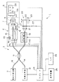
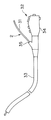
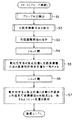
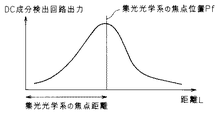
図1ないし図7は本発明の第1の実施の形態に係り、図1は本発明の第1の実施の形態の光走査型観察装置の全体構成を示し、図2は光走査プローブが挿通される内視鏡を示し、図3は光走査プローブの先端側の構成を示し、図4は光検出手段の構成を示し、図5は第1の実施の形態を光学特性が良好な状態に設定する処理手順を示し、図6は図5のステップS4のシャッタ閉の状態での光路長調整治具を移動した場合におけるDC成分検出回路の出力特性を示し、図7は低可干渉光のコヒーレンス長と集光光学系の被写界深度が異なる場合における許容される調整精度の説明図を示す。
(First embodiment)
1 to 7 relate to the first embodiment of the present invention, FIG. 1 shows the overall configuration of the optical scanning observation apparatus of the first embodiment of the present invention, and FIG. 2 shows the insertion of the optical scanning probe. 3 shows the configuration of the distal end side of the optical scanning probe, FIG. 4 shows the configuration of the light detection means, and FIG. 5 shows the first embodiment in a state with good optical characteristics. FIG. 6 shows the processing procedure to be set, FIG. 6 shows the output characteristic of the DC component detection circuit when the optical path length adjusting jig is moved in the shutter closed state in step S4 of FIG. 5, and FIG. 7 shows the coherence of the low coherence light. FIG. 5 is an explanatory diagram of allowable adjustment accuracy when the length and the depth of field of the condensing optical system are different.
図1に示すように本発明の第1の実施の形態の光走査型観察装置1は、光走査手段を内蔵し、生体組織に低可干渉性の光を集光照射すると共に、その反射光を受光する光走査プローブ2と、この光走査プローブ2の後端の光コネクタ4aが着脱自在に接続され、光走査プローブ2に低可干渉性の光を供給すると共に、光走査プローブ2からの戻り光を受光して画像化する光走査型観察装置本体(観察装置本体と略記)3とを有する。
As shown in FIG. 1, the optical
また、本実施の形態では光走査プローブ2の前端には駆動装置5により基準部材6が駆動(移動)自在となる光路長調整治具7が着脱自在に装着されるようになっている。
In this embodiment, an optical path
観察装置本体3内部には超高輝度発光ダイオード(以下、SLDと略記)等の低可干渉光源11が設けてある。この低可干渉光源11はその波長が例えば1300nmで、その可干渉距離が例えば17μm程度であるような短い距離範囲のみで干渉が起こる低可干渉光の特徴を備えている。つまり、この光を例えば2つに分岐した後、再び混合した場合には分岐した点から混合した点までの2つの光路長の差が17μm程度の短い距離範囲内の場合には干渉した光として検出され、それより光路長差が大きい場合には干渉しない特性を示す。
A low
この低可干渉光源11の光は(第1の)シングルモードファイバ12の一端に入射され、他方の端面(先端面)側に伝送される。
このシングルモードファイバ12は途中の光カプラ部13で(第2の)シングルモードファイバ14と光学的に結合されている。従って、この光カプラ13部分で2つに分岐(分離)されて伝送されると共に、分離されていた光をこのカプラ部13で結合させる機能も持つ。
The light from the low
This
シングルモードファイバ12の(光カプラ部13より)先端側には、光コネクタ受け4bが設けてあり、光走査プローブ2の光コネクタ部4aが着脱自在で接続され、この光走査プローブ2内に挿通されたシングルモードファイバ15に低可干渉性光源11の光が伝送(導光)される。
An
そして、伝送された光は光走査プローブ2の先端部のスキャナ部16に設けた(集光手段を構成する)集光光学系17を経て被検体(生体組織)側に2次元走査されながら集光照射される。
Then, the transmitted light is collected while being two-dimensionally scanned toward the subject (living tissue) through a condensing optical system 17 (constituting condensing means) provided in the
また、生体組織側の表面或いは内部で散乱などした反射光の一部が取り込まれ、逆の光路を経てシングルモードファイバ12側に戻り、光カプラ部13によりその一部がシングルモードファイバ14側に移り、そのシングルモードファイバ14の一端から光検出手段18で受光され、光電変換される。
Further, a part of the reflected light scattered on the surface or inside of the living tissue is taken in, returns to the
また、シングルモードファイバ14の光カプラ部13より先端側には偏光調整機19を介して基準光(参照光)の光路長を変える光路長可変機構20が設けてある。この光路長可変機構20は光走査プローブ2により集光光学系17の焦点位置で反射された光と光路長が一致するように調整設定して、その部分の光とのみ干渉して検出できるように基準光の光路長を可変設定できるようにするためのものである。
Further, an optical path
この光路長可変機構20はシングルモードファイバ14の先端にその焦点距離だけ離して対向するコリメータレンズ21と、このコリメータレンズ21により平行光束にされた光に対向して配置された(コヒーレンスゲートとしての)ミラー22と、このミラー22を光軸方向に移動設定する移動ステージ等の移動装置23とからなる。
The variable optical
上記光検出手段18は画像化する機能を備えたコンピュータ24と接続され、このコンピュータ24で画像化された画像信号は表示装置25に送られ、画像表示される。
The light detection means 18 is connected to a
また、このコンピュータ24にはインタフェース26が接続され、キーボード等からコンピュータ24に指示入力等を行うことができる。
このコンピュータ24は光プローブ2のスキャナ16の駆動を制御、偏光調整機19の偏光方向を調整制御、光路長可変機構20(の移動装置23)の制御を行う。
Further, an
The
また、本実施の形態では光走査プローブ2を観察装置本体3に接続して光走査画像を得る観察モードにする場合、その前の設定モードにおいて後述する調整機構により予め良好な光学特性の状態に設定する、つまり調整機構により光走査プローブ2の集光光学系17の焦点位置の部分での反射光を干渉光として検出できるように調整設定する。
Further, in this embodiment, when the
このため、光路長可変機構20には挿脱自在にシャッタ27が設けてある。このシャッタ27は使用開始時に実線で示すように光路内に挿入され、調整が終了後には2点鎖線で示すように光路外に(コンピュータ24の制御で)退避される。
For this reason, the optical path
シャッタ27が光路内に挿入された状態では、シングルモードファイバ14の先端から出射された光はシャッタ27で遮光され、シングルモードファイバ14の先端には入射されない状態となる。なお、図1(図8等でも同様)ではシャッタ27を光路内に入れた状態と外した状態とを分かり易く示しているが、実際にはシャッタ27を開閉することにより光路から挿脱したのと同様の機能を持たせることができる。
When the
また、光走査プローブ2の先端にはその先端に嵌合する光路長調整治具7が取り付けられ、この光路長調整治具7の内側には集光光学系17に対向して、光軸方向に移動自在の基準部材6が配置されている。
この基準部材6はモータ28を用いた送りネジ機構29により集光光学系17の光軸方向に移動される。このモータ28はコンピュータ24により回転駆動が制御される。
Further, an optical path
The
そして、後述するように(図1に示すように)シャッタ27を光路内に配置し、光走査プローブ2に光路長調整治具7を装着して、モータ28を回転させ、その場合に光検出手段18で検出される光の強度が最大となる状態に基準部材6を設定する。また、その状態でシャッタ27を光路から退避させ、干渉光が最大(極大)となる状態となるように移動装置23によりコヒーレンスゲートとして機能するミラー22の位置の調整(設定)を行う。
Then, as will be described later (as shown in FIG. 1), the
図2に示すように光走査プローブ2は細長で可撓性を有するシース31で覆われており、内視鏡32のチャンネル内に挿入可能である。内視鏡32は細長の挿入部33と、この挿入部33の後端に設けられた操作部34とを有し、操作部34の前端付近には挿入部33に設けられたチャンネルに連通する処置具挿入口35が設けてあり、光走査プローブ2を挿入することができる。
As shown in FIG. 2, the
そして、内視鏡32による観察下で、病変組織か否かを調べたいような場合には、チャンネル先端から光走査プローブ2の先端側を突出し、調べたい対象組織の表面近くに先端面を設定して光走査プローブ2による画像を得ることができるようにしている。
When it is desired to examine whether or not the tissue is a lesion under observation by the
シース31の内側にはシングルモードファイバ15が挿通されており、その先端側の構成を図3に示す。なお、図3では光路長調整治具7を取り付けた状態で示している。
シース31の先端は硬質のベース部材36により円筒状で硬質の先端カバー37と連結されている。
A
The distal end of the
また、このベース部材36には、スキャナ16を構成する変形可能な第1の薄板38aが取り付けられ、この第1の薄板38aの途中には中継部材39を介して変形自在の第2の薄板38bの後端が第1の薄板38aと直交するようにして取り付けられている。
Further, a deformable first
この第2の薄板38bの先端には集光光学系17を取り付けたホルダ40が連結部材41を介して保持されている。
A
また、第1の薄板38aの板面には板状の第1の圧電素子(図2では紙面の裏側))が取り付けられ、また第2の薄板38bの板面には板状の第2の圧電素子42bが取り付けられている。そして、第1の圧電素子及び第2の圧電素子42b(の板面にそれぞれ取り付けた電極)は駆動ケーブル43を介してコンピュータ24と接続され、交流の駆動信号を印加することにより第1の圧電素子及び第2の圧電素子42bを駆動して集光光学系17を直交する方向に駆動できるようにしている。
Further, a plate-like first piezoelectric element (in FIG. 2, the back side of the paper surface) is attached to the plate surface of the first
図3において、例えば第2の圧電素子42bを駆動した場合には、ホルダ40と共に、集光光学系17を上下方向(図3で示す座標系の場合にはX方向)に駆動する。また、第1の圧電素子を駆動した場合には、中継部材39を図3の紙面に垂直な方向に駆動し、この駆動により集光光学系17も紙面に垂直な方向(図3で示す座標系の場合にはY方向)に駆動する。
つまり、集光光学系17により出射される光をXY平面で2次元的に走査できるようにしている。なお、このスキャナ16の構成は図3に示すものに限らず、例えば特願2000−292546で図示された各種の構成のものを使用できる。
In FIG. 3, for example, when the second
That is, the light emitted from the condensing
また、カバー37の先端面における集光光学系17に対向して設けた開口部分には保護用のカバーガラス44で覆われている。
また、本実施の形態では、光走査プローブ2にはその光走査プローブ2に固有の識別情報(IDと略記)を発生するID部45(図1参照)が設けてあり、このID部45のIDはコンピュータ24により読み取られる。
Further, an opening provided on the front end surface of the
In this embodiment, the
そして、コンピュータ24はIDにより、その光走査プローブ2の光学特性を参照することにより、最適な光学特性の状態に設定するのに必要な調整範囲等を予め決め、IDを参照しない場合よりも最適な光学特性の状態に速やかに設定することができるようにしている。
Then, the
図4(A)は光検出手段18の構成を示す。
光検出手段18は、シングルモードファイバ14の端面から出射される光を受ける光検出素子18−1と、この光検出素子18−1で光電変換された信号を増幅するプリアンプ18−2と、このプリアンプ18−2で増幅された信号のDC成分を検出するDC成分検出回路18−3と、AC成分を検出するAC成分検出回路18−4と、DC成分検出回路18−3及びAC成分検出回路18−4からの出力信号を選択するスイッチ18−5と、スイッチ18−5で選択された信号をA/D変換するA/D変換器18−6とを有し、A/D変換器18−6から出力されるデジタル信号はコンピュータ24に入力される。
FIG. 4A shows the configuration of the light detection means 18.
The light detection means 18 includes a light detection element 18-1 that receives light emitted from the end face of the
なお、スイッチ18−5はコンピュータ24により切り換えられる。設定モードでは最初はDC成分検出回路18−3側に、その後観察モードの場合と同様にAC成分検出回路18−4側に切り換えられる。
図4(A)の構成の代わりに、図4(B)に示す第1変形例の構成のようにしても良い。
The switch 18-5 is switched by the
Instead of the configuration of FIG. 4A, the configuration of the first modification shown in FIG. 4B may be used.
図4(B)では、図4(A)の構成において、スイッチ18−5を設けないで、DC成分検出回路18−3の出力をA/D変換器18−6aでA/D変換して信号処理回路18−7に入力すると共に、AC成分検出回路18−4の出力をA/D変換器18−6bでA/D変換して信号処理回路18−9に入力するようにしている。さらに、信号処理回路18−9は入力された信号レベルに応じてゲインコントロール回路18−7を介してプリアンプ18−2のゲインを調整するようにしている。 4B, in the configuration of FIG. 4A, the output of the DC component detection circuit 18-3 is A / D converted by the A / D converter 18-6a without providing the switch 18-5. In addition to being input to the signal processing circuit 18-7, the output of the AC component detection circuit 18-4 is A / D converted by the A / D converter 18-6b and input to the signal processing circuit 18-9. Further, the signal processing circuit 18-9 adjusts the gain of the preamplifier 18-2 via the gain control circuit 18-7 according to the input signal level.
また、図4(B)の構成の代わりに、図4(C)に示す第2変形例の構成のようにしても良い。
図4(C)では、図4(B)の構成において、信号処理回路18−9は入力された信号レベルに応じてゲインコントロール回路18−7の代わりにゲイン・周波数調整回路18−8を介してDC成分検出回路18−3とAC成分検出回路18−4のゲインとAC成分を検出する際の周波数を調整するようにしている。
Further, instead of the configuration of FIG. 4B, the configuration of the second modification shown in FIG. 4C may be used.
In FIG. 4C, in the configuration of FIG. 4B, the signal processing circuit 18-9 passes through the gain / frequency adjustment circuit 18-8 instead of the gain control circuit 18-7 in accordance with the input signal level. Thus, the gain of the DC component detection circuit 18-3 and the AC component detection circuit 18-4 and the frequency at which the AC component is detected are adjusted.
次に本実施の形態の作用を図5のフローチャートを参照して説明する。
なず、図1に示すように光走査プローブ2を観察装置本体3に接続する。そして電源を投入すると、ステップS1に示すようにコンピュータ24は光走査プローブ2に設けたID部45のIDを読み込む。
Next, the operation of the present embodiment will be described with reference to the flowchart of FIG.
First, the
次にステップS2に示すように光走査プローブ2に光路長調整治具7を取り付ける。その後、ステップS3に示すようにキーボード等からコンピュータ24に光路調整開始の指示入力を行う。
Next, the optical path
すると、コンピュータ24はステップS4に示すようにシャッタ27を光路長可変機構20の光路内に挿入する。つまり、シャッタ27を閉じる。これにより、シングルモードファイバ14の先端から出射された光はシャッタ27により遮光され、シングルモードファイバ14の先端から出た光は、再びその先端には戻らない状態になる。つまり、干渉が起こらない状態に設定される。
Then, the
その後、コンピュータ24はモータ28に駆動信号を送り、モータ28を回転させることにより基準部材6を集光光学系17の光軸方向に移動すると共に、その状態での光検出手段18のDC成分検出回路18−3により検出される信号強度の最大(極大)となる状態に基準部材6を設定する処理を行う。
Thereafter, the
DC成分検出回路18−3により検出される信号強度は図6に示すように光路長調整治具7の基準部材6が集光光学系17の焦点位置Pfに設定された時、最大となる。図6において、横軸は集光光学系17からの調整治具7の基準部材6表面までの距離Lを示し縦軸はDC成分検出回路18−3の出力を示す。
つまり、ステップS5に示すように集光光学系17の焦点位置Pfに光路長調整治具7の基準部材6の表面の位置を一致させるようにする。
The signal intensity detected by the DC component detection circuit 18-3 becomes maximum when the
That is, as shown in step S5, the position of the surface of the
このように、光路長調整治具7の基準部材6の表面の位置を集光光学系17の焦点位置Pfに設定した後、ステップS6に示すようにシャッタ27を開、つまりシャッタ27を光路外に設定する。これにより、シングルモードファイバ14の先端から出た光は、再びその先端に戻る状態になる。つまり、干渉が起こる状態に設定される。
Thus, after setting the position of the surface of the
次にコンピュータ24は光路長可変機構20の移動装置23に制御信号を送り、ミラー20を光軸方向に移動させ、その状態における光検出手段18のAC成分検出回路18−4の検出出力が最大(極大)となる位置にミラー20を設定する。
Next, the
光路長可変機構20側の光路長を変化させると、光走査プローブ2側でその集光光学系17の焦点位置に基準部材6の表面を設定した状態における光走査プローブ2側による往路及び復路の光路長と、参照光が光路長変機構20側でミラー22で反射されて戻る往路及び復路の光路長とが低可干渉性の光で干渉する距離(コヒーレンス長)の範囲内になると干渉光となり、干渉光を検出するAC成分検出回路18−4により検出されるようになる。AC成分検出回路18−4ではフィルタ等を通したAC成分を検波するなどしてそのAC成分を検出する。
When the optical path length on the optical path
つまり、ステップS7に示すように光路長可変機構20側による参照光の光路長を、光走査プローブ2の集光光学系17が焦点位置Pfの状態での光路長と一致して干渉光として検出できるように参照光の光路長を決定するミラー位置の設定を行う(光走査プローブ2側の光路長と一致させる)。
That is, as shown in step S7, the optical path length of the reference light by the optical path
カバーガラス44と生体組織を接触させて観察する場合には基準部材6,カバーガラス44の間の空間に、生体の屈折率に近い物体を満たして調整を行うと、よりよい調整が行える。屈折率の近い物体とは、水やオイルやゲルなどが考えられ、屈折率1.3〜1.5程度のものが望ましい。
この様に、測定対象物に対して基準部材6、カバーガラス44の間の空間の屈折率を合わせた上で調整することにより、正確に調整が行える。
In the case of observing the
As described above, the adjustment can be performed accurately by adjusting the refractive index of the space between the
その後、この設定モードを終了し、観察モードに移る。つまり、光路長調整治具7を外し、光走査プローブ2を内視鏡32のチャンネル内に挿通して使用する。
Then, this setting mode is terminated and the observation mode is entered. That is, the optical path
この場合には、スキャナ16により集光光学系17は2次元的に走査され、集光光学系17の焦点位置で反射された光のみがその焦点位置と共焦点関係の位置に設定されたシングルモードファイバ15の小さなサイズの先端面に入射され、その光は光検出手段18のAC成分検出回路18−4により光路長可変機構20側の参照光と干渉した干渉光の信号として検出される。
In this case, the condensing
この信号はコンピュータ24のメモリ等に走査の情報と関連付けられて格納される。そして、走査された各部に対応した干渉光の信号が、コンピュータ24で画像化され、表示装置25に画像として表示される。
This signal is stored in the memory of the
本実施の形態によれば、実際に観察を行う観察モードに移る前に、上述して設定モードにより良好な光学特性の状態に簡単かつ円滑に設定することができる。 つまり、設定モードにより光走査プローブ2がその集光光学系17の焦点位置Pfの状態での往復の光路長(観察光側の光路長)と、参照光側の往復の光路長とをその光のコヒーレンス長の範囲内で一致させるように簡単かつ円滑に設定することができる。
従って、観察モードでは、良好な光学性能の状態、つまり焦点位置Pfで高い分解能の状態で観察像を得ることができる。
According to the present embodiment, it is possible to easily and smoothly set a state of good optical characteristics by the setting mode as described above before moving to the observation mode for actually observing. That is, depending on the setting mode, the
Therefore, in the observation mode, an observation image can be obtained in a state of good optical performance, that is, in a state of high resolution at the focal position Pf.
上述の説明では、光路長調整治具7の基準部材6の表面位置を集光光学系17の焦点位置Pfに設定すると共に、光路長可変機構20側の光路長を集光光学系17の焦点位置Pfの状態での光路長と一致させるように説明したが、実際には図7に示す場合が考えられる。
In the above description, the surface position of the
図7(A)では、コヒーレンス長は短く、これに対して集光光学系17の被写界深度が長い場合には、集光光学系17の被写界深度の距離範囲内の程度でコヒーレンス長(光路長可変機構20側でのミラー22の位置設定による光路長)が設定されれば良い。
In FIG. 7A, when the coherence length is short and the depth of field of the condensing
また、図7(B)では、図7(A)と反対のケースであり、コヒーレンス長は長く、これに対して集光光学系17の被写界深度が短い場合には、コヒーレンス長の距離範囲内の程度で光路長調整治具7側の基準部材6の位置設定が行われれば良い。勿論、上述のようにそれぞれがピークとなる位置に精度良く設定するに越したことがない。
FIG. 7B shows the opposite case to FIG. 7A, where the coherence length is long, and when the depth of field of the condensing
なお、上述では設定モードにおいて、シャッタ27により干渉光が発生しないように遮光して基準部材6の設定を行うように説明したが、減光する手段にして行うようにすることもできる。
In the above description, in the setting mode, the
なお、上述では例えば図2において、シングルモードファイバ14の小さな先端面から出た光は集光光学系17によりこの先端面と共焦点関係となる焦点位置(Pf)の部分で反射された光のみが先端面に戻ることができるように説明したが、この共焦点関係に近い状態に設定して観察像を得るようにしても良い。
In the above description, for example, in FIG. 2, the light emitted from the small tip surface of the
つまり、厳密に共焦点関係を満たす条件に設定すると、得られる光強度が弱くなり、S/Nが低下する可能性もあり、この共焦点関係に近い条件(例えばシングルモードファイバ14の先端面のサイズを少し広くし、共焦点関係の条件を僅かに外れた場合の光も検出できるようにする)に設定することにより、実質的にS/Nの良い観察像を得ることができる場合がある。 In other words, if the conditions are set so as to satisfy the confocal relationship strictly, the obtained light intensity becomes weak and the S / N may be lowered. The conditions close to this confocal relationship (for example, the tip surface of the single mode fiber 14). In some cases, it is possible to obtain an observation image having a substantially good S / N by setting the size to be a little wider and to detect light when the confocal relationship condition is slightly deviated. .
また、光走査プローブ2に採用したファイバとしてはシングルモードファイバ14で説明したが、これに限らず、マルチモードファイバでも良い。
また、光走査プローブ2を内視鏡32のチャンネル内に挿通可能として説明したが、内視鏡32に光走査プローブ2を設けるようにしても良い。
In addition, although the
Further, although the
また、上述の説明では設定モードにおいて、集光光学系17の焦点位置Pfに基準部材6の表面を一致させるように設定する場合、基準部材6の表面は光を反射するミラー面としてその反射光の強度が最大(極大)となるように基準部材6の表面位置を設定するように説明したが、この表面に反射部と無反射部を繰り返し設けた縞模様等にして、スキャナ16で光を走査して、その反射光を検出する状態にして、光検出手段18による検出出力が反射部と無反射部によるコントラスト信号の振幅が最大(極大)となる状態に基準部材6の表面位置を設定するようにしても良い。
In the above description, in the setting mode, when the surface of the
また、同様に光路長可変機構20側のミラー22の位置を設定する場合にもスキャナ16で光を走査し、その状態でコントラスト信号の振幅が最大(極大)となる状態の位置にミラー22を設定するようにしても良い。
Similarly, when setting the position of the
(第2の実施の形態)
次に本発明の第2の実施の形態を図8ないし図11を参照して説明する。図8は第2の実施の形態の光走査観察装置1Bの構成を示す。
この光走査観察装置1Bは、図1の光走査観察装置1において、光路長調整治具7及び駆動装置5を必要としない構造にしたものである。この光走査観察装置1Bはは光走査プローブ2Bと観察装置本体3Bとからなり、観察装置本体3Bには光路長調整治具7及び駆動装置5を設けていない。
(Second Embodiment)
Next, a second embodiment of the present invention will be described with reference to FIGS. FIG. 8 shows the configuration of the optical
This optical
その代わりに光走査プローブ2Bにはその先端側を集光光学系17の光軸方向に移動自在とする機能を持つ圧電素子51を設け、この圧電素子51はケーブル52によりコンピュータ24に接続され、設定モードにおいてこの圧電素子51をコンピュータ24により駆動できるようにしている。
Instead, the
図9(A)及び図9(B)は光走査プローブ2Bの先端側の構成を示し、図9(A)は例えば圧電素子51を駆動しない状態、図9(B)は圧電素子51を駆動して、この圧電素子51部分を収縮させた状態を示す。
9A and 9B show the configuration of the tip side of the
この光走査プローブ2Bは基本的に図3に示す光走査プローブ2の先端側を2重にして、その内側の部分を圧電素子51で集光光学系17の光軸方向に移動可能にしている。
This
つまり、図3に示す光走査プローブ2では、シース31とカバー37を固定しているベース部材36にスキャナ16の後端を取り付けていたが、図9に示す光走査プローブ2Bでは、シース31とカバー37を固定しているベース部材36に中空にし(てシングルモードファイバ15や駆動ケーブル43を通し)た圧電素子51を取り付け、この圧電素子51に第2のベース部材36bを介してホルダ40をスキャンするスキャナ16の後端を取り付けている。
That is, in the
この圧電素子51の(集光光学系17の光軸方向で対向する)両面の電極にはケーブル52の端部が接続され、例えばコンピュータ24から駆動信号が印加され、そのレベルに応じて圧電素子51は集光光学系17の光軸方向に収縮し、その収縮により集光光学系17の焦点位置が後方に移動する。
The ends of the
また、この第2のベース部材36bには第2のカバー37bを取り付け、そのカバー37bの前端の開口には第2のカバーガラス44bを取り付けている。 このカバー37bで覆われた部分が可動部53となっている。なお、第2のカバー37bは必ず必要なものではない。
A
次に本実施の形態の作用を図10のフローチャートを参照して説明する。
図10のフローチャートにおける処理は図5の処理においてステップS2の処理を省略し、ステップS5の代わりに圧電素子51を駆動して集光光学系17の焦点位置を光走査プローブ2B先端のカバーガラス44表面の位置に設定する処理(ステップS14)を行うものとなっている。
Next, the operation of the present embodiment will be described with reference to the flowchart of FIG.
The process in the flowchart of FIG. 10 omits the process of step S2 in the process of FIG. 5, drives the
このため、簡単にその作用を説明する。光走査プローブ2Bを観察装置本体3Bに接続して電源を投入すると、図5で説明したのと同様にステップS11のプローブのID読込を行い、次にステップS12の光路調整開始の指示を行う。すると、ステップS13に示すようにコンピュータ24はシャッタ27を閉じ、干渉光が検出されない状態にする。
Therefore, the operation will be briefly described. When the
そして、コンピュータ24は圧電素子51に駆動信号を送り、この圧電素子51を徐々に収縮させ、集光光学系17の焦点位置をその光軸上で集光光学系17側に移動させ、その際に光検出手段18のDC成分検出回路18−3の出力が最大となる状態にする。
The
集光光学系17が移動されてその焦点位置が(光走査プローブ2Bの)先端のカバーガラス44の表面の位置に設定されると、その表面での反射光が検出される状態となり、この状態で光検出手段18のDC成分検出回路18−3の出力が最大となる。
When the condensing
つまり、この処理はステップS14に示すように集光光学系17の焦点位置を光走査プローブ2B先端のカバーガラス44表面の位置に設定する処理となる。 この処理が行われた後、ステップS15に示すようにシャッタ27を開にして、干渉光が検出される状態にする。
That is, this process is a process of setting the focal position of the condensing
そして、ステップS16に示すようにカバーガラス44の表面位置に集光光学系17の焦点位置を設定して、この焦点位置からの反射光が戻る光路長の状態で、光路長可変機構側の光路長が一致するようにミラー22の位置を設定する。
Then, as shown in step S16, the focal position of the condensing
つまり、ミラー22を移動させながら光検出手段18のAC成分検出回路18−4の出力が最大となる状態にミラー22の位置を設定する。
この処理が終了したら、設定モードの処理が終了し、観察モードに移ることができる。
That is, the position of the
When this process is finished, the setting mode process is finished, and the mode can be shifted to the observation mode.
なお、この場合には、カバーガラス44の表面が焦点位置となっているので、観察モードではカバーガラス44の表面から所望とする距離に焦点位置を設定するには、圧電素子51に対応するレベルの信号を印加し、またその距離に等しい距離だけミラー22を離す方向に移動設定すれば良い。
In this case, since the surface of the
この説明から分かるように、本実施の形態では光路長調整治具7を不必要にできると共に、集光光学系17の深さ方向に対して焦点位置を可変設定すると共に、光路長可変機構20側の光路長もそれに同期して可変設定することにより深さ方向の光走査画像を得ることもできる。
As can be seen from this description, in this embodiment, the optical path
つまり、本実施の形態によれば、集光光学系17をスキャナ16でスキャンすることにより2次元画像を得ることもできるし、圧電素子51を駆動して深さ方向にも走査させると3次元画像を得ることも可能となる。
That is, according to the present embodiment, a two-dimensional image can be obtained by scanning the condensing
上述の説明では、圧電素子51を収縮させることにより、集光光学系17の焦点位置をカバーガラス44の表面位置に設定できるとして説明したが、圧電素子51による可変範囲が狭いような場合には、図11に示すように光走査プローブ2Bの先端面にキャップ状の調整治具55を取り付け、この調整治具55の凹部の基準面55aに集光光学系17の焦点位置を設定するようにしても良い。
この場合には光走査プローブ2Bの先端面から離間した基準面55aの位置が焦点位置となった状態での光走査画像を得ることになる。
In the above description, it has been described that the focal position of the condensing
In this case, an optical scanning image is obtained in a state where the position of the reference surface 55a that is separated from the tip surface of the
(第3の実施の形態)
次に図12ないし図15を参照して本発明の第3の実施の形態を説明する。図12は本発明の第3の実施の形態の光走査観察装置1Cを示す。この光走査観察装置1Cは光走査プローブ2Cと観察装置本体3Cとからなる。
(Third embodiment)
Next, a third embodiment of the present invention will be described with reference to FIGS. FIG. 12 shows an optical scanning observation apparatus 1C according to the third embodiment of the present invention. This optical scanning observation apparatus 1C includes an
この光走査プローブ2Cは図8の光走査プローブ2Bにおける圧電素子51の代わりにZ駆動カム61を設けて集光光学系17を含む先端側を移動自在とし、その手元側に設けたモータ62でこのZ駆動カム61を駆動するようにしている。また、このモータ62の回転軸にはエンコーダ63に接続されている。モータ62及びエンコーダ63はモータドライバ64を介してコンピュータ24に接続されている。
This
モータ62はコンピュータ24の制御によりモータドライバ64を介して駆動され、かつその回転位置を検出するエンコーダ63の出力信号はモータドライバ64を介してコンピュータ24に入力される。
The
図13は光走査プローブ2Cの先端側の構成を示す。図9で説明した可動部53がこの光走査プローブ2Cの先端側に設けられ、その可動部53の先端面がバネ65により後方側に付勢されており、この可動部53の後端面から後方側にピン66が突出するように設けてある。
FIG. 13 shows the configuration of the tip side of the
また、シース31内にはモータ62の回転軸に連結され、回転駆動されるフレキシブルシャフト67が挿通され、このフレキシブルシャフト67の先端には先端面を斜めに切り欠いた斜面部68aを設けた回転部材68が取り付けられ、この回転部材68はベース部材36で回転自在に支持されている。
Further, a
可動部53はバネ65により後方側に付勢されているので、ピン66は回転部材68の斜面部68aを押圧する状態を維持する。そして、モータ62によりフレキシブルシャフト67を介して回転部材68が回転されることにより、ピン66が回転部材68の斜面部68aで押圧されて可動部53は集光光学系17の光軸方向、つまり(図3の座標系でZ軸方向、つまり被検体に対する深さ方向)に進退移動を行う。
Since the
可動部53が集光光学系17の光軸方向に進退移動を繰り返すことにより、集光光学系17の焦点位置もその可動部53の進退移動量だけ光軸方向に移動する。その移動の際に集光光学系17の焦点位置はカバーガラス44の先端表面より後方側にまで移動できるように設定してある。
When the
その移動範囲が狭い場合には、図13の2点鎖線で示すように治具55を取り付けることで、焦点位置が治具55の表面、つまり基準面55a位置を含む範囲移動できるようにすれば良い。
If the movement range is narrow, by attaching the
図14は本実施の形態の作用のフローチャートを示す。光走査プローブ2Cを観察装置本体3Cに接続し、電源を投入することによりステップS21に示すように光走査プローブ2CのID読込が行われる。次にステップS22の光路調整開始の指示を行う。
FIG. 14 shows a flowchart of the operation of the present embodiment. By connecting the
この指示により、モータ62が回転し、ステップS23に示すように可動部53と共に、集光光学系17はその光軸方向(深さ方向ともいう)にスキャンを開始する。また、ステップS24に示すようにコンピュータ24の制御によりシャッタ27は閉となり、干渉光が検出されない状態になる。
By this instruction, the
この状態で光検出手段18のDC成分検出回路18−3の出力が最大となる状態の深さ或いはその深さのタイミングをエンコーダ63の出力で検出する。つまり、集光光学系17の焦点位置がカバーガラス44の表面位置に一致した時に、DC成分検出回路18−3の出力が最大となり、その時のタイミングはエンコーダ63の出力から検出できる。
In this state, the depth of the state in which the output of the DC component detection circuit 18-3 of the light detection means 18 becomes maximum or the timing of the depth is detected by the output of the
つまりステップS25に示すように、集光光学系17の焦点位置が光走査プローブ2Cの先端のカバーガラス44の表面位置に一致する深さ(又はその深さ情報のデータの取込タイミング)を観測したデータの取込タイミングに設定する処理を行う。
That is, as shown in step S25, the depth at which the focal position of the condensing
その後、ステップS26に示すようにシャッタ27を開にし、その後ステップS27に示すように集光光学系17の焦点位置がカバーガラス表面位置に一致したデータ取込タイミングの時における光検出手段18のAC成分検出回路18−4の出力(つまり干渉光の検出出力)が最大となるようにミラー22の位置を設定する。
その後、観察モードに移る。
Thereafter, the
Then, it moves to observation mode.
一方、移動範囲が狭くて調整治具55を用いる場合には、図15に示す処理を行うことになる。図15に示す処理は図14におけるステップS21とS22との間に調整治具55を取り付ける処理を行う(ステップS28)。
On the other hand, when the movement range is narrow and the
また、図14のステップS25の代わりにステップS25′を行う。このステップS25′は、ステップS25におけるプローブ先端のカバーガラス44の表面位置の代わりに調整治具55の基準面55a位置と置き換えたものに相当する。また、同様に図14のステップS27を図15のステップS27′に示すように変更する。ここでも、カバーガラス44の表面位置を調整治具55の基準面55a位置に置き換えたものとなる。
Further, step S25 ′ is performed instead of step S25 in FIG. This step S25 'corresponds to a replacement of the surface position of the
本実施の形態によれば、エンコーダ63の出力により、最適な光学特性になった状態のタイミングで光検出手段18の出力を取り込むことにより、第2の実施の形態と同様に焦点状態で被検体に対する2次元画像を得ることができるし、光路長可変機構20によるミラー22の位置を変えることにより、第2の実施の形態で説明したのと同様に3次元画像を得ることも可能となる。
According to the present embodiment, the output of the light detection means 18 is captured at the timing when the optimum optical characteristics are obtained by the output of the
(第4の実施の形態)
次に図16及び図17を参照して本発明の第4の実施の形態を説明する。図16は本発明の第4の実施の形態の光走査観察装置1Dを示す。この光走査観察装置1Dは光走査プローブ2と観察装置本体3Dとからなる。
(Fourth embodiment)
Next, a fourth embodiment of the present invention will be described with reference to FIGS. FIG. 16 shows an optical scanning observation apparatus 1D according to the fourth embodiment of the present invention. This optical scanning observation apparatus 1D includes an
本実施の形態における観察装置本体3Dは、図1においてシングルモードファイバ14の先端と光路長可変機構20との間に変調を行う変調手段71を設け、観察モード或いは光路可変機構20側の参照光を用いる場合にはコンピュータ24により変調動作を行うように制御する構成にしている。
そして、この場合における光検出手段72は、図17に示す構成となっている。
The observation apparatus main body 3D in the present embodiment is provided with a modulation means 71 that performs modulation between the tip of the
In this case, the light detection means 72 has the configuration shown in FIG.
図17に示すように光検出手段72は、シングルモードファイバ14の端面から出射される光を受ける光検出素子72−1と、この光検出素子72−1で光電変換された信号を増幅するプリアンプ72−2と、このプリアンプ72−2で増幅された信号における変調手段71の変調周波数以下の周波数成分を通すバンドパスフィルタ(BPFと略記)72−3と、このバンドパスフィルタ72−3を通過した成分における包絡線信号成分、つまり低域周波数成分を検出するローパスフィルタ72−4と、プリアンプ72−2の出力、バンドパスフィルタ72−3を通過した出力、ローパスフィルタ72−4を通過した出力とがそれぞれ接続された接点a、b、cを選択するスイッチ72−5と、このスイッチ72−5で選択された信号をA/D変換するA/D変換器72−6と、このA/D変換器72−6の出力が入力される信号処理回路72ー8と、この信号処理回路72ー8の出力によりプリアンプ72−2、バンドパスフィルタ72−3、ローパスフィルタ72−4のゲインを制御するゲイン・周波数調整回路72ー7とから構成される。
As shown in FIG. 17, the light detection means 72 includes a light detection element 72-1 that receives light emitted from the end face of the
上記バンドパスフィルタ72−3とローパスフィルタ72−4とは変調手段71を復調する手段を形成している。そして、変調手段71を用いた場合には、スイッチ72ー5のa,bを適宜に切り換える。
シャッタ27を閉にして光路調整を行う場合には接点cに設定してその出力が最大となるように調整する。なお、スイッチ72ー5はコンピュータ24によりその切り換えの制御が行われる。その他は図1と同様の構成である。
The band pass filter 72-3 and the low pass filter 72-4 form means for demodulating the modulation means 71. When the modulation means 71 is used, a and b of the switch 72-5 are switched appropriately.
When the optical path adjustment is performed with the
本実施の形態では、変調手段71により参照光側を変調するようにしているので、その変調された参照光と干渉する光成分をよりS/Nの良い状態で参照光の光路長の設定や、観察モードにおける干渉光の検出ができる。 In the present embodiment, the modulation means 71 modulates the reference light side, so that the optical component that interferes with the modulated reference light can be set with a better S / N and the optical path length of the reference light can be set. The interference light in the observation mode can be detected.
図18は変形例の光走査観察装置1Eを示す。この光走査観察装置1Eは例えば図8において、光路長可変機構20のシャッタ27を開閉自在にしていたが、光路長可変機構20自体をシングルモードファイバ14の先端の光路から挿脱自在にしてシャッタ27を不要とした装置本体3Eにしたものである。
FIG. 18 shows a modified optical scanning observation apparatus 1E. In this optical scanning observation apparatus 1E, for example, in FIG. 8, the
つまり図8では設定モードにおいてはコンピュータ24によりシャッタ27は光路から退避(及び介挿)されるが、図18では光路長可変機構20が光路から退避(及び介挿)される。図18では光路長可変機構20が光路中に介挿されている状態を実線で、退避された状態を2点鎖線で示している。
That is, in FIG. 8, in the setting mode, the
なお、図18の変形例では図8の装置の場合に適用したが、他の装置の場合に適用しても良い。
また、シャッタ27の代わりに反射光が戻る強度を小さくした減光フィルタ等を採用しても良い。
In addition, in the modification of FIG. 18, although applied to the case of the apparatus of FIG. 8, you may apply to the case of another apparatus.
Further, instead of the
以下、図面を参照して本発明に係る光断層イメージング装置の複数の実施の形態を説明する。 Hereinafter, a plurality of embodiments of an optical tomographic imaging apparatus according to the present invention will be described with reference to the drawings.
(第5の実施の形態)
まず、図19及び図20に基づき、第5の実施の形態に係わる光断層イメージング装置の構成を説明する。図19は、第5の実施の形態に係わる光断層イメージング装置の構成を示す構成図である。図20は、光走査プローブ105の先端の構成を説明するための図である。
(Fifth embodiment)
First, based on FIG.19 and FIG.20, the structure of the optical tomographic imaging apparatus concerning 5th Embodiment is demonstrated. FIG. 19 is a configuration diagram showing a configuration of an optical tomographic imaging apparatus according to the fifth embodiment. FIG. 20 is a diagram for explaining the configuration of the tip of the
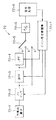
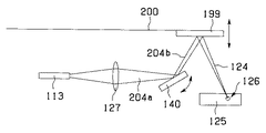
図19において、低コヒーレンス光源101から出射した近赤外の低コヒーレンス光は、第1の光ファイバ106に導光され、4つの入出力を有する光カプラ108によって第3の光ファイバ109と第4の光ファイバ110に分岐される。第3の光ファイバ109にはエイミングビームレーザ103からの出射した可視レーザ光が光カプラ112により合波される。第3の光ファイバ109は、光コネクタ104により第5の光ファイバ113に接続され、光走査プローブ105に低コヒーレンス光を伝送する。
In FIG. 19, the near-infrared low-coherence light emitted from the low-
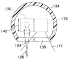
光走査プローブ105の先端部の構成は、図20に示される。第5の光ファイバ113端部から出射された低コヒーレンス光は、集光レンズ127によって観察光(観察ビーム)124として観察対象125内部の観察点126に集光される。第5の光ファイバ113の端部と集光レンズ127からなる対物ユニット130は、光走査手段128を有し、観察光124および観察点126を2次元方向に動かしながら、被検体である観察対象125を走査する。また、対物ユニット130は、焦点移動手段としての深さ方向走査手段129に接続され、観察点126を観察対象の深さ方向に走査することができる。光走査手段128および深さ方向走査手段129は、図19の走査駆動手段122により駆動される。すなわち、焦点移動手段は、集光レンズ127と光走査手段129を一体として光軸方向に移動する。
The configuration of the tip of the
光走査プローブ105は、細い柔軟な管状であるので、直接または径内視鏡的に、さらには径脈管的に体腔内に容易に挿入可能である。また、観察光学系を有する内視鏡そのものとして構成することも可能である。
Since the
第4の光ファイバ110は周波数シフタ111に接続され、周波数シフタ111の出力は、第6の光ファイバ114に導光される。周波数シフタ111としては、音響光学素子(AOM)や、電気光学素子(EO)、ピエゾ素子にファイバループを設けたもの等の位相変調手段を用いることができる。
The fourth
第6の光ファイバ114端部から出射した光は、コリメータレンズ115を介して可動ミラー116に導光される。可動ミラー116は、ミラー駆動手段117によって出射光の光軸方向に移動することができる。第6の光ファイバ114の端部、コリメータレンズ115、可動ミラー116及びミラー駆動手段117により、光路長調節手段118が構成されている。
Light emitted from the end of the sixth
光カプラ108の残りの端子である第2の光ファイバ107は光ディテクタ102に接続されている。第1の光ファイバ106、第2の光ファイバ107、第3の光ファイバ109、第4の光ファイバ110、第5の光ファイバ113及び第6の光ファイバ114としては、好ましくはシングルモードファイバまたは、コヒーレンス性を十分に維持することの可能な低次マルチモードファイバ、偏波保持ファイバなどを用いることができる。
The second
低コヒーレンス光源101から出射した近赤外の低コヒーレンス光は、第1の光ファイバ106に導光され、光カプラ108より第3の光ファイバ109と第4の光ファイバ110に分岐される。第3の光ファイバ109に導光された光は、光コネクタ104、第5の光ファイバ113を介して光走査プローブ105に導光され、観察対象125に観察光124として出射される。
Near-infrared low-coherence light emitted from the low-
観察光124および観察点126による走査は、光走査手段128及び深さ方向走査手段129によって観察対象125に対して行われる。観察点126における観察対象125からの反射光あるいは散乱光は、集光レンズ127を介して第5の光ファイバ113に戻り、経路を逆に辿るように第3の光ファイバ109に戻る。この光の経路を物体側132とする。
Scanning with the
同様に、第4の光ファイバ110に分岐した低コヒーレンス光は、周波数シフタ111で周波数遷移が行われ、第6の光ファイバ114を介してコリメータレンズ115に出射される、コリメータレンズ115に入射した光は、略平行光に変換され、可動ミラー116へ導かれる。可動ミラー116で反射した光は、再びコリメータレンズ115によって第6の光ファイバ114に導かれ、第4の光ファイバ110に戻る。この光の経路を参照側133とする。
Similarly, the low-coherence light branched into the fourth
物体側132と参照側133の2つの光が、光カプラ108により混合される。光物体側132の光路長と参照側133の光路長が低コヒーレンス光源101のコヒーレンス長の範囲で一致した場合には、第2の光ファイバ107を通った、周波数シフタ111の周波数遷移量の等倍または2倍の周波数の変動を有する干渉光が、光ディテクタ102によって検出される。ここで、参照側133の光路長を物体側の観察点126までの光路長に一致するように、光路長調節手段118のミラー駆動手段117により可動ミラー116の光軸方向の位置を予め調整しておくことによって、観察点126からの情報が干渉光として常に得られることになる。
The two lights on the
この検出された干渉光は、光ディテクタ102により電気信号に変換される。その電気信号は、復調器119へ供給される。周波数シフタ111の周波数遷移量の等倍、2倍又は高次倍の周波数近傍の信号だけを復調器119によって取り出すことによって、観察点126からの信号を光ヘテロダイン検出により高S/N比で検出できる。走査駆動手段122により観察光124の観察点126を略垂直および深さ方向に2次元に動かすことによって走査が行われる。その走査の制御信号と同期して、アナログディジタル(A/D)コンバータ120を介して復調器119の信号は、走査駆動手段122からの観察点126の走査位置信号に対応してパーソナルコンピュータ(以下、PCと略す)121に取り込まれる。観察点126の走査位置信号に対応して復調信号を輝度によってPC121のディスプレイ123に表示することにより、観察対象125の深さ方向の2次元の断層像を得ることができる。
The detected interference light is converted into an electric signal by the optical detector 102. The electric signal is supplied to the demodulator 119. The signal from the
次に、図21から図27を用いて光走査プローブ105の詳細を説明する。
Next, details of the
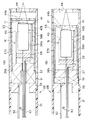
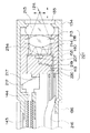
図21は、光走査プローブ105の先端部の構成を示す断面図である。図20で説明された対物ユニット130は、集光レンズ127、第5の光ファイバ113およびその端部を固定するフェルール139、走査ミラー140、マグネット141、レンズ枠138により構成される。フェルール139によって固定された第5の光ファイバ113の端部から出射された光は、走査ミラー140によって方向が変えられ、集光レンズ127により集光されて観察光24となり、観察点126に集光される。走査ミラー140、マグネット141および集光レンズ127は、図20で示された光走査手段128を構成している。走査ミラー140は、駆動ケーブル153を介して駆動電流によって揺動され、観察光124を偏向し、観察点126が移動して、図示される光軸に対し略垂直な方向に観察対象125を走査することができる。
FIG. 21 is a cross-sectional view showing the configuration of the tip of the
図23は、走査ミラー140の詳細構成を説明するための図である。走査ミラー140は好ましくはシリコン製であり、半導体製造プロセスと同様のプロセスで製造することができる。走査ミラー140において、実際に光を反射させるX軸揺動ミラー169が捩れ部171a、171bによりY軸揺動板168に弾性的に保持されている。X軸揺動ミラー169は、Y軸揺動板168に対してX軸方向の走査ができるように入射光を揺動する。X揺動ミラー169は表面が反射面となっており、裏面には、点線で示すようにX軸駆動コイル174およびX軸検出コイル175が設けられている。X軸駆動コイル174を通電することにより、マグネット141により発生する静磁界に対して回転力が生じ、X軸揺動ミラー169が揺動する。またマグネット141により発生する静磁界に対してX軸検出コイル175が揺動することにより起電力が発生し、この起電力を検出することによって揺動の速度をモニタすることができる。
FIG. 23 is a diagram for explaining a detailed configuration of the
同様に、Y揺動板168は捩れ部170a、170bにより支持枠182に弾性的に保持されている。Y軸揺動板168は、表面にY軸駆動コイル172およびY軸検出コイル173が設けられている。Y軸駆動コイル172を通電することにより、マグネット141により発生する静磁界に対して回転力が生じ、Y軸揺動板168が揺動する。またマグネット141により発生する静磁界に対してY軸検出コイル173が揺動することにより起電力が発生し、この起電力を検出することによって揺動の速度をモニタすることができる。
Similarly, the
従って、X軸駆動コイル174およびY軸駆動コイル172を通電し、通電によって発生した起電力をX軸検出コイル175およびY軸検出コイル173によってモニタしながら制御し、X軸揺動ミラー169をXとYの2つ自由度において揺動することによって、観察光124および観察点126を偏向し、2次元方向に観察対象125を走査することができる。
Therefore, the
光走査プローブ105の先端は硬性のハウジング134に覆われており、観察光124が透過する部分にガラスなどの透明体で構成された観察窓135が設けられている。ハウジング134は、柔軟性のチューブで構成される樹脂製のシース136に糸巻き接着部137で接続されている。シース136は、プローブの略全長に設けられたフレキシブルな外筒である。対物ユニット130が、ピポット147を支点として揺動可能に保持されることによって、焦点移動手段が構成されている。板バネ148は、レンズ枠138を接触面149において回転カム145に押し付けると共に、ピポット147においてハウジング134とレンズ枠138を接するように押圧する。
The tip of the
回転カム145は、回転軸144に固定接続され、回転軸144は、ハウジング134に設けられたベアリング152により回転自在に保持されている。回転カム145と回転軸144は、変位変換機構を構成する。回転軸144は、動力伝達手段としてのフレキシブルシャフト143に接続されている。フレキシブルシャフト143は、光走査プローブ5の軸方向に設けられている。従って、フレキシブルシャフト143の回転が、観察対象125の深さ方向の動きに変換され、対物ユニット130が移動する。
The
図24は、図21のVIで示す点線部において矢印の方向から見た、回転カム145とレンズ枠138が接触面149で接触している部分の断面図を示す。図24に示すように、回転カム145は、回転軸144に対して偏心している。レンズ枠138は、板バネ148により、回転カム145側に付勢されているために、回転軸144が回転すると、回転カム145によってレンズ枠138が上下、すなわち第5の光ファイバ113の光軸に対して略直交する方向に揺動する。この上下方向の動きは、ピポット147を支点とするテコの原理を利用して拡大され、対物ユニット130は、矢印142で示す上下方向に動く。これにより観察点126も上下方向の動きを行う。
FIG. 24 is a cross-sectional view of a portion where the
上述した観察点126の光軸に対する2次元走査と、その2次元平面に鉛直な上下方向の動きを組み合わせることによって、観察対象を3次元的に走査することができる。その結果、その走査に対応して低コヒーレンス干渉により観察点からの反射光または散乱光の情報を得ることで3次元的な像を得ることができる。もちろん、例えば走査ミラー140の駆動を1次元に制限し、その1次元方向と上下方向の2つの方向の走査によって、2次元断層像を得るように構成することも可能である。
By combining the above-described two-dimensional scanning with respect to the optical axis of the
また、ハウジング134の内部には生体と略同一の屈折率を有する屈折率整合液151が封入されている。走査ミラー140の液浸を防止するために、レンズ枠138、フェルール139、マグネット141、駆動ケーブル153及び集光レンズ127は液密になるように接着封止されている。また、回転軸144にはOリング146による液密シールが設けられ、屈折率整合液151をハウジング134内に封止している。
In addition, a refractive index matching liquid 151 having substantially the same refractive index as that of a living body is sealed inside the
図25は、図21のVIIで示す点線部において矢印の方向から見た、光走査プローブ105の観察点126を含む断面図を示す。対物ユニット130と略平行に撮像ユニット176が設けられている。
FIG. 25 is a cross-sectional view including the
図26は、撮像ユニット176の断面図である。撮像ユニット176は、レンズ群179、プリズム180、CCD178、CCD信号ケーブル181、撮像ユニット枠183より構成されている。観察範囲177の内の光が、レンズ群179及びプリズム180によりCCD178に結像され、観察範囲177の視野範囲が観察される。図25に示されるように撮像ユニット176の観察範囲177に観察点126が含まれるように、対物ユニット130と撮像ユニット176は設けられ、観察光124と撮像ユニット176の視野範囲は、共通の観察窓135の範囲内に含まれる。言い換えると、観察光124と撮像ユニット176の視野範囲の光のために、共通の観察窓125が使用される。この場合、図19に示されるように観察光124には可視光であるエイミングビームが導入されているので、内視鏡視野と、光断層像観察範囲の位置を対応付けて理解することが可能になる。すなわち、内視鏡の撮像手段による観察範囲内に、光走査手段による光走査範囲が含まれる。また、CCD178が可視領域以外の近赤外光にも感度を有するので、エイミングビームとして非可視光のエイミングビームを利用してもよい。さらにまた、CCD178の感度領域の波長の低コヒーレンス光源を用いることで、エイミングビームレーザ103を使わずに光断層像観察範囲を確認することが可能である。
FIG. 26 is a cross-sectional view of the
図27は、光走査プローブ105のシース136の断面図である。シース136内部には、シース内腔と略同一の径のマルチルーメンチューブ150が設けられている。マルチルーメンチューブ150は、3つの貫通穴を有する。第1の貫通穴184には第5の光ファイバ113が挿通されている。第2の貫通穴185にはフレキシブルシャフト143が挿通されている。第3の貫通穴186には、CCD信号ケーブル181と、走査ミラー駆動ケーブル153を束ねた信号ケーブル154が挿通されている。マルチルーメンチューブ150を用いると組立性の向上、実装密度の向上が可能であるという利点がある。また、マルチルーメンチューブ150の代わりに複数の単チューブを用いてもよい。
FIG. 27 is a cross-sectional view of the
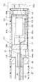
図22は、光走査プローブ105の基端部の断面図である。シース136とマルチルーメンチューブ150がコネクタハウジング155に接続されている。コネクタハウジング155は、取り付け用ネジ部を有する取付部材156により着脱自在に観測装置ハウジング157に接続される。ベアリング162によって回転自在に回転伝達受け158が、コネクタハウジング155に設けられ、回転伝達受け158の軸がフレキシブルシャフト143に接続されている。観測装置ハウジング157には、モータ166と、モータ回転角および速度を検出するエンコーダ167が設けられ、モータ166軸に回転伝達シャフト159が接続されている。回転伝達シャフト159にはピン受け部161が設けられ、回転伝達受け158にはピン160が設けられている。モータ166の回転が、回転伝達シャフト159へ、ピン受け部161へ、ピン160へ、回転伝達受け158へ、そしてフレキシブルシャフト143へと伝達される。その結果、前述のように、フレキシブルシャフト143に伝達された回転によって対物ユニット130が上下動し、観察点126が観察対象125の深さ方向に移動することによって、深さ方向の走査が行われる。また、コネクタハウジング155及び観測装置ハウジング157に、第5の光ファイバ113と第3の光ファイバ109を接続する光コネクタ163b及び163aが設けられている。また、ケーブル165と信号ケーブル154を接続する電気コネクタ164a及び164bが設けられている。
FIG. 22 is a cross-sectional view of the proximal end portion of the
また、この光走査プローブ105は内視鏡も兼ねており、通常の内視鏡と同様に図示しない処置具挿通チャンネル、観察窓135を清掃するための送気・送水機構、湾曲機構等を有している。
The
図28は、深さ方向走査手段29の別の構成例を説明するための図である。図10は、図21との相違点を説明するために、その相違点のみを示す。図21のレンズ枠138と板バネ148の代わりに、板バネ187に上に対物ユニット130が設けられている。その他は、図21と同様にフレキシブルシャフト143により回転カム145を回転させ対物ユニット130を、図28の紙面において上下方向に、すなわちフレキシブルシャフト143に鉛直な方向に動かすことによって、深さ方向の走査が行われる。
FIG. 28 is a diagram for explaining another configuration example of the depth
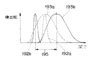
図29から図34は、低コヒーレンス干渉による干渉位置と集光位置の関係を説明するための図である。例えば、図29に示すように、集光レンズ127は、空気中190(屈折率n=1)中に設けられており、生体組織91(屈折率n=nt)の表面付近を観察しているものとする。このとき、集光レンズ127による集光点である観察点126と、光路長189で規定される低コヒーレンス干渉による干渉位置188とは一致している。これにより観察点126の情報を高分解能で得ることができる。これを深さと検出能の関係を示したのが図30のグラフである。図30において、横軸は深さを、縦軸は検出能を表している。192aは低コヒーレンス干渉による検出効率を表しており、193aは集光レンズ127の集光力による検出効率を表している。この2つのを掛け合わせたものが全体の検出効率となるので、干渉位置188における観察点126の検出能が高いことが分かる。
FIG. 29 to FIG. 34 are diagrams for explaining the relationship between the interference position due to the low coherence interference and the light collection position. For example, as shown in FIG. 29, the
ところが、図31に示すように、図20に示す深さ方向走査手段129を用いて観察点126を生体組織191中深くに走査した場合、観察点126の位置は空気中での観察点の位置194より深い位置となる。走査量をΔdepthとした場合、(nt−1)×Δdepth分だけ深い走査量となる。
However, as shown in FIG. 31, when the
一方、低コヒーレンス干渉位置188は空気中での観察点の位置194に対し、走査量をΔdepthとした場合、(1−1/nt)×Δdepth分だけ浅くなっている。
On the other hand, the low
従って観察点126と低コヒーレンス干渉位置188の深さ位置には差195が生じている。その差は、(nt−1)×Δdepth+(1−1/nt)×Δdepthである。
Therefore, there is a
図32は、この差を説明するための図である。低コヒーレンス干渉の検出効率192aのカーブは浅い側に192bのように移動し、集光力による検出効率193aのカーブは深い側に193bのように移動している。ここで低コヒーレンス干渉の検出効率192bと集光力による検出効率193bを掛け合わせたものが全体の検出効率なので、系全体としては低い検出効率になり、深さ方向の情報が得られないことがわかる。
FIG. 32 is a diagram for explaining this difference. The curve of the
そこで図33に示すように、図19の光路長調整手段118によって、光路長を差195だけ増して、低コヒーレンス干渉の検出効率192bのカーブを192cのように深さ方向に移動し、観察点126の深さ位置と低コヒーレンスの干渉位置188を一致させる。これによって、観察点126の情報を高い検出効率で得ることができる。最初から生体内部の定まった範囲を観察する場合は、生体内部のある深さに対して高い検出効率を有するように、光路長調整手段118により光路長を調節することによって、生体内部を高効率でかつ高い水平分解能で観察することが可能になる。
Therefore, as shown in FIG. 33, the optical path length adjusting means 118 in FIG. 19 increases the optical path length by a
図35及び図36は、観察点126の位置と低コヒーレンス干渉位置188を一致させる別の方法を説明するための図である。
FIG. 35 and FIG. 36 are diagrams for explaining another method for matching the position of the
屈折率がnsの透明な素材で構成されたハウジング196の内部には、生体の屈折率ntと略同じの屈折率を有する屈折率整合液197が満たされている。屈折率整合液197の中に防液ハウジング198とその内部に集光レンズ127が設けられている。
Inside the
ここで、防液ハウジング198先端から観察点126までの光路長は次の通りである。
Here, the optical path length from the tip of the liquid-
光路長1=(ntL1+nsL2+L3+ntL4=nt(L1+L4)+nsL2+L3)
ここで、図20に示されたような深さ方向走査手段129を用いて集光レンズ127と防液ハウジング198を深さ方向に走査量Δdepth分だけ走査した場合、図36に示すように、
L1’=L1−Δdepth
L4’=L4+Δdepth
となるので、
光路長2=(ntL1’+nsL2+L3+ntL4’)
=nt(L1−Δdepth+L4+Δdepth)+nsL2+L3
=nt(L1+L4)+nsL+L3=光路長1
と光路長の変化はない。
Here, when the condensing
L1 ′ = L1−Δdepth
L4 ′ = L4 + Δdepth
So,
= N t (L1−Δdepth + L4 + Δdepth) + n s L2 + L3
= N t (L1 + L4) + n s L + L3 =
There is no change in the optical path length.
また,それぞれの屈折率(nt,ns,1)を通過する距離が走査後も同じなので観察点126もΔdepthだけ移動する。従って、観察点126の位置と、低コヒーレンス干渉の干渉位置188は深さ方向の走査全域に渡って一致し、高い検出効率と高い水平方向の分解能を維持できる。
Further, since the distances passing through the respective refractive indexes (n t , n s , 1) are the same after scanning, the
また、図21における観察窓135の被検体側の部分の表面(界面)に、被検体の屈折率に対して反射防止になるような、屈折率の整合層としての反射防止膜を設けると、観察窓の材質の屈折率と被検体の屈折率差から生じるフレネル反射を防ぎ、ノイズ光を減らし、S/N比を向上させることが出来る。同様のことを観察窓135および集光レンズ127の屈折率整合液151との接触面(界面)にも設けることができる。
Further, when an antireflection film as a refractive index matching layer is provided on the surface (interface) of the portion on the subject side of the
以上のように、本実施の形態によれば、光プローブの軸方向に設けられたフレキスブルな動力伝達手段によって、焦点移動手段が駆動されるので、先端硬質部の寸法が短く、かつ精密な制御の可能な焦点可変機構を有する光走査プローブ装置を実現することができる。 As described above, according to the present embodiment, since the focal point moving means is driven by the flexible power transmission means provided in the axial direction of the optical probe, the size of the hard tip portion is short and precise control is performed. Thus, an optical scanning probe device having a variable focus mechanism can be realized.
また、動力伝達手段に伝達される力量と変位が一意的な関係にある変位変換機構を用いることで、変位でなく力量により焦点位置の移動量を制御でき、変位がプローブの湾曲等で変動する場合にも制御しやすい。 In addition, by using a displacement conversion mechanism in which the amount of force transmitted to the power transmission means and the displacement have a unique relationship, the amount of movement of the focal position can be controlled by the amount of force, not the displacement, and the displacement varies with the curvature of the probe. Easy to control even when.
さらに、集光手段と被検体の間に、集光手段と被検体の間隔を変更可能で、透明な軟性の被検体と略同一の屈折率を有する屈折率整合物質を有する屈折率整合手段が設けられているので、界面からの反射を抑制し、S/N比を向上させることができる。 Further, there is provided a refractive index matching means having a refractive index matching substance having a refractive index substantially the same as that of a transparent soft subject, the distance between the light collecting means and the subject being changeable. Since it is provided, reflection from the interface can be suppressed and the S / N ratio can be improved.
(第6の実施の形態)
図37に第6の実施の形態を示す。第5の実施の形態と異なる部分のみを図面を用いて説明し、その他の部分は第5の実施の形態と同じ番号で示し、説明は省略する。
(Sixth embodiment)
FIG. 37 shows a sixth embodiment. Only parts different from the fifth embodiment will be described with reference to the drawings, and other parts are denoted by the same reference numerals as those of the fifth embodiment, and description thereof will be omitted.
第5の光ファイバ113より出射した光は集光レンズ127により集光される。その光線204aは、図23に示された走査ミラー140によって走査され光線204bとなり、板バネ200に設けられた反射ミラー199によって反射され、観察光124となり、生体組織125に照射される。板バネ200は、図28と同様なフレキシブルシャフト143と回転カム145を用いた機構や、図示されない板バネ200を吸着する電磁石や板バネ200に設けられたピエゾ素子、または板バネをSMA(形状記憶合金)で構成し、それに電流を流すことで湾曲させるアクチュエータなどの公知のアクチュエータによって上下に走査するように動かされる。上下に走査するように動かされることによって、観察点126が深さ方向に走査される。図20の光走査手段128と深さ方向走査手段129を用いて、観察点126を水平方向および深さ方向に走査することにより2次元または3次元の断層像を得ることができる。
The light emitted from the fifth
また、図38に走査ミラー140を保持する走査ミラーユニット201を示す。走査ミラーユニット201には走査ミラー140の近傍に観察光124の通過するための穴202が設けられている。走査ミラーユニット201は好ましくは半導体製造プロセスにより走査ミラー140と同時に作成され、穴202を走査ミラーユニット201に設けることにより観察光124を生体組織125に対しより垂直に近く入射させることができ、より効率の高い観察が可能である。
FIG. 38 shows a
図39に第6の実施の形態の変形例を示す。反射ミラー199の代わりに、上面に反射面206が設けられているくさび型プリズム203をロッド205により図の水平方向に移動、すなわちチューブ状のシース136の軸方向に沿って動かすことにより、図37の反射ミラー199を上下に走査するのと同様に生体組織125に対し深さ方向に走査することができる。くさび型プリズム203は生体組織と略同一の屈折率を有しており、図35と図36の屈折率整合液197と同様に、観察点126と、低コヒーレンス干渉の干渉位を深さ方向の走査全域に渡って一致させ、高い検出率と高い水平方向の分解能を維持できるという効果を有する。
FIG. 39 shows a modification of the sixth embodiment. Instead of the reflecting
(第7の実施の形態)
図40に第7の実施の形態を示す。第5の実施の形態と異なる部分のみを図面を用いて説明し、その他の部分は第5の実施の形態と同じ番号で示し、説明は省略する。
(Seventh embodiment)
FIG. 40 shows a seventh embodiment. Only parts different from the fifth embodiment will be described with reference to the drawings, and other parts are denoted by the same reference numerals as those of the fifth embodiment, and description thereof will be omitted.
第5の光ファイバ113より出射した光は集光レンズ127により光線209bとなり板バネ200端に設けられた曲面ミラー208によって観察光124となり、被検体の観察点126に集光する。第5の光ファイバ113の出射端207は第5の光ファイバ113端部より数mm基端側に設けられたピエゾ素子113aにより紙面に垂直な方向に振動する。それにより集光レンズ127に入射する光線209aの角度が変化し光線209bが紙面に垂直な方向に走査される。曲面ミラー208は、集光レンズ127と被検体の間に設けられている。可動ミラーである曲面ミラー208が第6の実施の形態で示された図示しないアクチュエータにより上下により駆動され、観察点126は近似的に、光走査プローブ105の軸方向に垂直な方向に走査される。曲面ミラー208の移動によって、焦点位置は、略直線状に移動する。従って、ピエゾ素子113aによる水平方向の走査と曲面ミラー208による観察深さ方向の走査によって断層像を得ることができる。
The light emitted from the fifth
図41および図42に第7の実施の形態の変形例を示す。曲面ミラー208の代わりに曲面回転ミラー210が設けられ、曲面回転ミラー210はフレキシブルシャフト143により駆動される偏心軸を有している。図42は図41の光走査手段120の断面図である。第5の光ファイバ113出射端207から出射した光は集光レンズ127によって光線209bとして出射する。集光レンズ127および第5の光ファイバ113の出射端207はバイモルフピエゾ素子211a、211bによって上下に走査され、光線209bも上下(図41では紙面に垂直)に走査される。深さ方向走査手段としての曲面回転ミラー210は、フレキシブルシャフト143の駆動により回転し、可動ミラーである曲面ミラー208を上下走査したのと同様に、観察点126を上下に、すなわち光走査プローブ105の軸方向に垂直な方向に走査することができる。
41 and 42 show a modification of the seventh embodiment. A curved
焦点移動手段に、集光手段と被検体の間に設けられた可動ミラーを用いたので、高速な焦点位置の変更をすることができる。 Since the movable mirror provided between the light collecting means and the subject is used as the focus moving means, the focus position can be changed at high speed.
(第8の実施の形態)
図43に第8の実施の形態を示す。第5の実施の形態と異なる部分のみを図面を用いて説明し、その他の部分は第5実施例と同じ番号で示し、説明は省略する。
(Eighth embodiment)
FIG. 43 shows an eighth embodiment. Only parts different from the fifth embodiment will be described with reference to the drawings, and other parts are denoted by the same reference numerals as those in the fifth embodiment, and description thereof will be omitted.
光走査ユニット221は、レンズ枠218、集光レンズ213、光導波路基材220、走査ミラー140より構成される。第5の光ファイバ113を伝送された光は光導波路219を経由して、出射端217より出射し、走査ミラー140中央に設けられた穴234を通して集光レンズ213上に設けられた反射ミラー214を介して走査ミラー140に導光される。走査ミラー140は第5の実施の形態の図23のような電磁式のものでも、特開平11−84250号公報に示された静電式のものでも良い。
The
走査ミラー140により方向を変えた光は集光レンズ213により観察点126に集光される。走査ミラー140の揺動により観察点は光軸に略垂直な方向に走査される。光走査ユニット221はハウジング134内において集光レンズ213の光軸方向に可動であり、回転カム212と光導波路基材220に設けられた突起217で接触している。フレキシブルシャフト143の回転が回転軸144により回転カム212に伝達される。透明弾性部材215は、屈折率整合液を充填した樹脂の袋であり、被検体側に設けられた透明板である観察窓135と、集光レンズ213の間に設けられている。光走査ユニット221は透明ゴムやゲルなどの透明弾性部材215により付勢されており、回転カム212の回転によって突起217が右方向に押され、光走査ユニット221は図の左右方向に移動し、観察点126がフレキシブルシャフト143の回転に応じて左右に、すなわち観察対象の深さ方向に走査される。また、第5の光ファイバ113と駆動ケーブル153は一本のケーブル216に構成されている。透明弾性部材215は生体組織と略同一の屈折率を有するため、観察点126と低コヒーレンス干渉の干渉位置188は深さ方向の走査全域に渡って一致し、高い検出効率と高い水平方向の分解能を維持できる。
The light whose direction has been changed by the
図44から図46は第8の実施の形態の深さ方向走査手段の変形例を示す。 44 to 46 show modifications of the depth direction scanning means of the eighth embodiment.
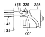
図44では、フレキシブルシャフト143の回転が回転軸144を介しておねじ222に伝達される。図43の光走査ユニット221に固定されためねじ223を左右に、すなわち深さ方向に移動させることができる。この実施の場合、フレキシブルシャフトの回転力に対して負荷が大きくとも駆動可能という特徴を有する。図45は、フレキシブルシャフト143により回転カム224を回転し、回転カム224に設けられたカム溝230上を光走査ユニット221上に固定されたロッド225の突起231が移動することによりロッド225を左右に、すなわち深さ方向に移動可能である。図46は図45の回転カム224の代わりにフレキシブルシャフト143に直結して回転するギア226とハウジング134に設けられた軸227に回転自在に設けられた回転カム228で構成するもので、フレキシブルシャフト134の回転ギア部229で減速され回転カム228に伝達され、図45よりも大きな駆動力を得ることができる。
In FIG. 44, the rotation of the
(第9の実施の形態)
図47および図48に第9の実施の形態を示す。第5の実施の形態と異なる部分のみ図面を用いて説明し、その他の部分は第5の実施の形態と同じ番号で示し、説明は省略する。図47は、第9の実施の形態に係る光走査プローブの先端部の構成を示す断面図であり、図48は、ハウジングの断面図である。
(Ninth embodiment)
47 and 48 show a ninth embodiment. Only parts different from the fifth embodiment will be described with reference to the drawings, and other parts are denoted by the same reference numerals as those of the fifth embodiment, and description thereof will be omitted. FIG. 47 is a cross-sectional view showing the configuration of the distal end portion of the optical scanning probe according to the ninth embodiment, and FIG. 48 is a cross-sectional view of the housing.
光走査ユニット221は、第5の実施の形態および第8の実施の形態の構成と同様であるが、第5の光ファイバ113からの出射端207から出射した光が反射ミラー233を介して走査ミラー140に導かれることである。またレンズ枠218に液密パッキン232が設けられていることである。
The
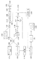
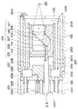
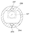
ハウジング134には、送水パイプ235が接続され、送水ノズル240に接続される第1の送水管237、第1のシリンダ246まで貫通する第2の送水管238、第2のシリンダ247まで貫通する第3の送水管239、送水パイプ235に送られた液体を駆動ケーブル250に伝達された駆動信号に基づいて第1の送水管237、第2の送水管238及び第3の送水管239に供給する送水バルブ236が設けられている。
A
また、同様にハウジング134には、吸引パイプ241が接続され、吸引口248に接続される第1の吸引管243、第1のシリンダ246まで貫通する第2の吸引管244、第2のシリンダ247まで貫通する第3の吸引管245、図示されない駆動ケーブル250と同様の駆動ケーブルに伝達された駆動信号に基づいて第1の吸引管243、第2の吸引管244及び第3の吸引管245のいずれかと吸引パイプ241を接続する吸引バルブ242が設けられている。
Similarly, the
送水パイプ235と吸引パイプ241には図示されない観測装置の有する送水手段と吸引手段と流体コネクタを介して着脱可能に接続されており、それぞれに常時加圧された水および陰圧が加えられている。
The
この送水バルブ236と吸引バルブ242を駆動することにより光走査ユニット221を一体として、左右に、すなわち観察対象125の深さ方向に移動し、観察点126の深さ方向の走査を実現する。
By driving the
送水バルブ236により送水パイプ235と第2の送水管238を接続し、同時に吸引バルブ242により吸引バルブ242と第3の吸引管247を接続する。すると、第1のシリンダ246に水が注入され、第2のシリンダ247の水が除去される。第1と第2のシリンダの圧力の差で光走査ユニット221が左方向へ移動し、観察点126は浅い方向に移動する。
The
送水バルブ236により送水パイプ235と第3の送水管239を接続し、同時に吸引バルブ242により吸引パイプ241と第2の吸引管244を接続すると反対に光走査ユニット221が右方向へ移動し、観察点126は深い方向に移動する。
When the
また送水バルブ236により送水パイプ235と第1の送水管237を接続すると、送水ノズル240から水を噴出することができ、観察窓135を洗浄することができる。また吸引バルブ242により吸引パイプ241と第1の吸引管243を接続すると、吸引口から過剰な水を吸引することができる。
When the
また、光走査ユニット221の走査は、第2の送水管238と第2の吸引管244、または第3の送水管239と第3の吸引管245のみでも行うことができる。
Further, the scanning of the
ここでは深さ方向の走査に用いられる液体を水としたが、生体と近い屈折率を有する液体(n=1.3〜1.5)であれば他の液体(例えば生理食塩水やグリセリンなど)を用いることも当然可能である。 Here, the liquid used for scanning in the depth direction is water, but other liquids (for example, physiological saline, glycerin, etc.) are used as long as the liquid has a refractive index close to that of a living body (n = 1.3 to 1.5). ) Is naturally possible.
第9の実施の形態の変形例を図49及び図50に示す。第9の実施の形態と異なる部分のみ説明し、その他の部分は第9の実施の形態と同じ番号で示す。 A modification of the ninth embodiment is shown in FIGS. Only parts different from the ninth embodiment will be described, and the other parts are denoted by the same reference numerals as those in the ninth embodiment.
光走査ユニット221の先端側に生体とおおよそ等しい屈折率を持った液体を封入した、透明な樹脂、好ましくはPET(ポリエチレンテレフタレート)やポリウレタンで構成されたダイヤフラム266が設けられている。ダイヤフラム266には一体に構成された管267が設けられている。ダイヤフラム266に管267を経由して液体を導入、あるいは吸引することで、ダイヤフラム266内の屈折率整合液の体積を増加あるいは減少させ、光走査ユニット221を左右に移動させ、上述した第9の実施の形態と同様に深さ方向の走査を行うことが可能である。光走査ユニット221は右端部はダイヤフラム266に接着されているが、接着せずに光走査ユニット221をダイヤフラム266に図示しない付勢手段により圧接させても良い。
A
第5の光ファイバ113には、光走査ユニット221の進退によるたるみを吸収するためにループ状に形成されたファイバたるみ吸収部268が設けられている。このようなファイバたるみ機構は、上述した第8の実施の形態及び第9の実施の形態に示す構成に設けても有効である。
The fifth
図50に示されるように光走査ユニット221のレンズ枠218には、図49のハウジング134に設けられたガイド269とそれに対向して設けられたガイド溝270が設けられ、光走査ユニット221が回転せずに進退させることができる。
As shown in FIG. 50, the
この変形例の構成により流体駆動機構であっても水密機構を単純にでき、小型に構成することが可能となる。 With this configuration of the modified example, even if it is a fluid drive mechanism, the watertight mechanism can be simplified and can be configured in a small size.
(第10の実施の形態)
図51から図53に第10の実施の形態を示す。第5の実施の形態と異なる部分のみ図面を用いて説明し、その他の部分は第5の実施の形態と同じ番号で示し、説明は省略する。
(Tenth embodiment)
51 to 53 show a tenth embodiment. Only parts different from the fifth embodiment will be described with reference to the drawings, and other parts are denoted by the same reference numerals as those of the fifth embodiment, and description thereof will be omitted.
図51は、第10の実施の形態に係る光走査プローブの先端部の構成を示す断面図である。図52は、第10の実施の形態に係る中空バネの構造の例を説明するための図である。図53は、第10の実施の形態に係る中空バネの構造の他の例を説明するための図である。 FIG. 51 is a cross-sectional view showing the configuration of the tip of the optical scanning probe according to the tenth embodiment. FIG. 52 is a view for explaining an example of the structure of the hollow spring according to the tenth embodiment. FIG. 53 is a view for explaining another example of the structure of the hollow spring according to the tenth embodiment.
第5の光ファイバ113と、集光レンズ127及びレンズ枠218によって、レンズユニット265が構成される。レンズユニット265に接続されたバイモルフ型ピエゾ素子211a、接続部材263、及び取付台253に接続されたバイモルフ型ピエゾ素子211bによって、図20の光走査手段128が構成される。レンズユニット265と光走査手段128によって、対物ユニット130が構成される。第5の光ファイバ113からの出射端207から出射した光は集光レンズ127により観察点126に導かれ、再び出射端207に戻るが、その観察光124は、バイモルフ型ピエゾ素子211aにより上下方向に、バイモルフ型ピエゾ素子211bにより紙面の垂直方向、すなわち上下方向に垂直な方向に走査され、両者を合わせる事により、第5の実施の形態と同様に2次元的な走査が可能である。
The fifth
取付台253、中空バネ252、駆動シャフト254、永久磁石255、電磁石256、LED260、フォトダイオード261、反射体262、ディテクタ台259、中継シース258及び中継台257によって深さ方向走査手段129が構成されている。
A depth direction scanning means 129 is configured by the mounting
電磁石256に駆動電流を与えると、駆動電流に比例した駆動力が永久磁石255に生じるので、駆動シャフト254により取付台253に伝達される。その結果、観察対象125の深さ方向に焦点の観察点が移動する。取付台253には前述のバイモルフ型ピエゾ素子211bの端部が固定されている。また、取付台253は、中空バネ252のバネ部252aの途中に設けられた固定部252bに固定されている。また、中空バネ252の両端はハウジング部材134に固定されている。
When a driving current is applied to the
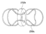
中空バネ252の構造の例を図52及び図53に示す。中空バネ252の1例として、図52には、超弾性合金(SEA)のパイプに切り込み263を設けたものが、図53には、バネ部252aを線バネで構成し、それに固定部252bを接合したものが示されている。前述の通り永久磁石255と電磁石256によって電磁力アクチュエータが構成され、電磁力アクチュエータによる駆動力により取付台253が左右に、すなわち光りプローブ105の軸方向に移動し、対物ユニット130に設けられたレンズユニット265を深さ方向に移動させ、観察点126が深さ方向に移動する。永久磁石255と電磁石256による駆動力が無くなると中空バネ252の復元力により取付台253は元の位置に復元する。
Examples of the structure of the
取付台253の位置、すなわち深さ方向の走査位置は、ハウジング134に固定されたディテクタ台259に設けられた光源としてのLED260から照射した光が、反射体262で反射した光の強度または光量を、検出器であるフォトダイオード261で検出することで得ている。すなわち、焦点移動量の検出は、光走査プローブ105の先端部において、焦点移動手段の固定部と可動部間の距離を測定して行う。また、電磁石の駆動電流は駆動力に比例し、その駆動力は中空バネ252の弾性力とおおよそ釣り合う。弾性力は移動変位の関数になるため、電磁石の駆動電流から取付台253の位置を推定する事も可能である。なお、LED260とフォトダイオード261の代わりに、磁気発生器と磁気検出器を設けて、磁力の変化で走査位置を検出するようにしてもよい。
The position of the mounting
また、電磁石256の設けられた中継台257は、アクチュエータ保持部材であり、シース136と接続される。更に、軸方向の剛性が高く、軸に垂直な方向には低剛性の材質で構成される中継シース158により、中継台257は、ハウジング134に接続される。また前述の駆動シャフト254も同様に軸方向の剛性が高く、軸に垂直な方向には低剛性の材質で構成されている。焦点移動手段を有する硬質の先端光学部と、その光学部とアクチュエータ保持部材の間にフレキシブルな外筒すなわちシース136が設けられている。これにより大きな駆動力を持つアクチュエータは一般的に大きくなりがちであるが、アクチュエータ部と、光学部を分離することによって、硬質長を短くし、体腔内での挿入性や取扱い性、特に内視鏡の処置具チャンネル挿通使用時の挿入性や取扱い性を向上させている。
The
また、第5の光ファイバ113のバイモルフ型ピエゾ素子211aおよびバイモルフ型ピエゾ素子211bを駆動するための駆動ケーブル153を内蔵するケーブル216の剛性は高いので、ケーブル216と駆動シャフト254を兼ねる構成が可能である。これによりプローブ内部の空間使用の効率を上げる事で、プローブを更に細径化する事が可能となる。
In addition, since the
また、図52に示すような構成で中空バネ252を形状記憶合金(SMA)により構成し、端部の一方のみをハウジング134に固定する。そして、更に図示しない加熱手段、例えばSMA自身に電流を通電すること、および好ましくは水などの冷却手段を設けることによってアクチュエータとバネ手段を兼ねる構成が可能である。
52, the
また本構成に示されるような、アクチュエータ部と光学部を分離し、駆動シャフト254と中継シース258により駆動力を伝達する構成は、他の実施の形態、例えば第8の実施の形態に適用することも可能である。回転カム212と突起217による直動駆動力を駆動シャフト254に伝達し、駆動シャフト254により光走査ユニット221を進退させることも可能である。
Moreover, the structure which isolate | separates an actuator part and an optical part as shown by this structure, and transmits a driving force with the
図54に、第10の実施の形態の変形例を示す。第10の実施の形態と異なる部分のみ説明し、その他の部分は第10の実施の形態と同じ番号で示す。 FIG. 54 shows a modification of the tenth embodiment. Only parts different from the tenth embodiment will be described, and the other parts are denoted by the same reference numerals as those in the tenth embodiment.
対物ユニット130はバネ座273に固定されている。バネ座273とハウジング134の間には、第10の実施の形態の中空バネ252の代わりにバネ定数k1の圧縮バネA271を設け、バネ座273と駆動シャフト254の間はバネ定数k2の引っ張りバネB272を設ける。対物ユニット130の進退量xは、駆動シャフト254の進退量yとすると、x=(k2/k1)yの関係にある。これらのバネ271と272によって、変位変換機構が構成される。k2をk1に対し小さく設定することで、永久磁石255、電磁石256からなるアクチュエータの変位量を縮小して伝達することができる。これにより対物ユニット130を位置決めするのが容易になる。
The
なお、ここでは、変位変換機構を、2種類のバネによって構成したが、2種類以上のバネ定数を有する複数のバネによって構成してもよい。また、ここでは、変位を縮小する機構で説明したが、変位を拡大する機構を用いてもよい。変位変換機構は、動力伝達手段に伝達される力量と変位量が一意的な関係になるように構成されている。 Here, the displacement conversion mechanism is configured by two types of springs, but may be configured by a plurality of springs having two or more types of spring constants. Further, here, the mechanism for reducing the displacement has been described, but a mechanism for increasing the displacement may be used. The displacement conversion mechanism is configured such that the amount of force transmitted to the power transmission means and the amount of displacement have a unique relationship.
また、上述したような永久磁石255と電磁石256からなるアクチュエータを設けず、駆動シャフト254を充分フレキシブルなワイヤとして、光走査プローブの全長に渡って挿通し、プローブの手元でワイヤを手動または図示しないアクチュエータにより引っ張ることで、プローブ先端の対物ユニット130を、深さ方向に、すなわちプローブの軸方向に動かして位置決めすることが可能である。
Also, the actuator composed of the
このとき、位置を第10の実施の形態に示されたLED260、フォトダイオード261、照射反射体262からなる位置検出手段によりモニタしながら位置決めすることができる。
At this time, the position can be determined while being monitored by the position detecting means comprising the
この構成では一般にはワイヤ駆動ではμmオーダーの微小な位置決めを行うことは困難であるが、バネA271、バネB272による変位縮小機構により、ワイヤ駆動による位置決め機構を実現できる。この構成ではアクチュエータをプローブ手元部または外部に構成できるのでプローブ先端をより小型に構成できるという利点を有する。 In this configuration, it is generally difficult to perform fine positioning on the order of μm by wire driving, but a positioning mechanism by wire driving can be realized by a displacement reduction mechanism by springs A271 and B272. This configuration has the advantage that the probe tip can be configured more compactly because the actuator can be configured on the probe hand or outside.
ワイヤ駆動のためのアクチュエータとしては、第8の実施の形態に係る図44、45、46に示されたネジやカムによる直動機構や、プーリによるワイヤ巻取り機構を用いることもできる。また一般的な市販の大型アクチュエータを用いることが出来、さらにはプローブ外部に設けることも可能なので、プローブを安価に構成することが可能である。 As an actuator for driving a wire, the linear motion mechanism using a screw or a cam shown in FIGS. 44, 45 and 46 according to the eighth embodiment, or the wire winding mechanism using a pulley can be used. In addition, a general commercially available large actuator can be used, and furthermore, since it can be provided outside the probe, the probe can be configured at low cost.
(第11の実施の形態)
図55から図58に第11の実施の形態を示す。第5の実施の形態と異なる部分のみ図面を用いて説明し、その他の部分は第5の実施の形態と同じ番号で示し、説明は省略する。
(Eleventh embodiment)
55 to 58 show an eleventh embodiment. Only parts different from the fifth embodiment will be described with reference to the drawings, and other parts are denoted by the same reference numerals as those of the fifth embodiment, and description thereof will be omitted.
光走査プローブ105の外装はフレキシブルな樹脂から構成されるプローブシース275とそれに接続された透明シース274よりなる。プローブシース275の内部には直動シャフト276が設けられ、その先端に対物ユニット279が設けられている。対物ユニット279には第5の光ファイバ113の端部と集光レンズ127が設けられている。透明シース274内部にはモータ277とDOE(回折光学素子)ミラー278が設けられている。
The exterior of the
第5の光ファイバ113の端部から出射した観察光124は、DOE走査ミラー278に反射され、観察点126に集光する。DOE走査ミラー278を図56に示す。DOEミラーは281a〜fまで6つのDOEミラーからなっている。DOEミラー281aで説明すると、DOEミラー281aには図56から正面から入射する光線を、284bで示す下方に反射するように回折格子が形成されている。DOE回転ミラー278を回転させると、光線の向きが284aから284cへ移動する。DOEミラー281bからfも281aと同様にDOEミラーで構成されているため、モータ277にDOE走査ミラー278を回転させると、光線は284aから284cへ繰り返し走査される。これにより観察点126が円弧状に走査される。これが第5の実施の形態の光走査手段128に対応している。
The observation light 124 emitted from the end of the fifth
また、直動シャフト276をプローブ先端方向に移動することにより対物ユニット279を押し出し、位置285に移動することで、集光点126を位置286に移動できる。これが第5の実施の形態の深さ方向走査手段130になっており、観察対象125内での観察深さを変更できる。
Further, by moving the
また、DOE走査ミラー278の代わりに、図57及び図58に示すような角錐ミラー282を用いることもできる。図57は、角錐ミラー282の正面図である。図58は、角錐ミラー282とモータ277の側面図である。角錐ミラー282は反射面283a−dを持ち、角錐ミラー282を回転させることで、DOE走査ミラー278と同様の作用を行うことができる。
Further, instead of the
(第12の実施の形態)
図59に第12の実施の形態を示す。第5の実施の形態と異なる部分のみ図面を用いて説明し、その他の部分は第5の実施の形態と同じ番号で示し、説明は省略する。
(Twelfth embodiment)
FIG. 59 shows a twelfth embodiment. Only parts different from the fifth embodiment will be described with reference to the drawings, and other parts are denoted by the same reference numerals as those of the fifth embodiment, and description thereof will be omitted.
本発明は、図19と異なった構成の干渉計を用いても実施可能である。第3の光ファイバ109に導光された光は光サーキュレータ293により光ファイバ287に導かれ、光コネクタ104を介して第5の光ファイバ113に導かれる。その光は光走査プローブ105に導かれ、観察対象より戻ってきた光は再び光ファイバ287に導かれるが、光サーキュレータ293により光ファイバ288に導かれる。
The present invention can also be implemented using an interferometer having a configuration different from that shown in FIG. The light guided to the third
また第4の光ファイバ110に導かれた光はコリメータ294aにより周波数シフタ111に導かれ、コリメータ294bにより光ファイバ289に導かれる。光ファイバ288に導かれた光と光ファイバ289に導かれた光は光カプラ290によって混合され、光カプラ290からの光はディテクタ291aと291bに導かれる。ここで、第3の光ファイバ109から光サーキュレータ293を経由し、光走査プローブ105に導光され、観察対象に対し出射し、反射された光が光サーキュレータ293を経由し、光ファイバ288を通して光カプラ290に導かれる光路の光路長を物体側の光路長とする。また、第4の光ファイバ110から周波数シフタ111を経由し、光ファイバ289を通して光カプラ290に導かれる光路の光路長を参照側の光路長とする。
The light guided to the fourth
すると、第5の実施の形態と同様に、物体側の光路長と参照光の光路長が低コヒーレンス光源のコヒーレンス長の範囲内で一致した場合に干渉光が得られる。 Then, as in the fifth embodiment, interference light is obtained when the optical path length on the object side matches the optical path length of the reference light within the range of the coherence length of the low-coherence light source.
ここで、ディテクタ291aと291bで受けられる干渉光から生じる信号は位相が反対であり、それ以外の定常光、雑音光により生じる信号は同相であるため、差分増幅器292でディテクタ291aと291bの信号の差分を増幅すると、干渉信号は倍になり、雑音成分は抑制するため、S/N比を大きく向上させることが出来る。
Here, since the signals generated from the interference light received by the
また、低コヒーレンス光源1の代わりにコヒーレンス長の長いレーザ光源を用いると、干渉顕微鏡と同等の性能を得ることが可能である。また、第5の実施の形態における図19に示される参照側133の構成を用いず、第4の光ファイバ110を屈折率整合物質等で終端すると、レーザ光走査型顕微鏡が構成できる。このとき、図20に示される第5の光ファイバ113の光学径、集光レンズ127の入射NA(開口数)及び出射NAが、共焦点条件を満たせば、走査型共焦点顕微鏡になる。この場合には、光ディテクタ102として好ましくは、光電子倍増管や、アバランシェフォトダイオードなど、光電子変換時に増幅特性を有する検出素子が用いられる。この場合には周波数シフタ111による変調はなされないので、復調器119は不要である。
Further, when a laser light source having a long coherence length is used instead of the low coherence
上記第5から第12の実施の形態における各構成要素を組み合わせて、光断層イメージング装置を構成することができ、またそれぞれの効果を得られることは自明である。例えば、第10の実施の形態に係る図51の永久磁石255と電磁石256によりアクチュエータの代わりに、第5の実施の形態に係る図47に示される流体アクチュエータを用いることが出来る。この場合、流体ではなく、気体を用いることも出来る。
It is obvious that the optical tomographic imaging apparatus can be configured by combining the components in the fifth to twelfth embodiments, and the respective effects can be obtained. For example, the fluid actuator shown in FIG. 47 according to the fifth embodiment can be used instead of the actuator by the
さらにまた、光走査プローブ内にアクチュエータを設け、アクチュエータがフレキシブルな動力伝達手段を駆動するように構成した場合、そのアクチュエータは、電磁力アクチュエータのようなプローブの軸方向に動きを与えるもの、回転駆動を与えるものなどであってもよい。そして、アクチュエータと焦点可変機構をフレキシブルな動力伝達手段で接続し、動力伝達手段がある部分はフレキシブルに構成する。 Furthermore, when an actuator is provided in the optical scanning probe, and the actuator is configured to drive a flexible power transmission means, the actuator is one that moves in the axial direction of the probe, such as an electromagnetic force actuator, or is rotationally driven. It may be a thing which gives. Then, the actuator and the focus changing mechanism are connected by a flexible power transmission means, and a portion where the power transmission means is provided is configured to be flexible.
以上説明した第5から第12の実施の形態の夫々は、次のような効果を有する。 Each of the fifth to twelfth embodiments described above has the following effects.
(1)先端硬質部が短く、精密な制御の可能な焦点可変機構を有する光走査プローブを提供することができる。 (1) It is possible to provide an optical scanning probe having a focal point variable mechanism with a short tip hard portion and capable of precise control.
(2)フレキシブルな直道の動力伝達手段であっても精密な制御を可能にする光走査プローブを提供することができる。 (2) It is possible to provide an optical scanning probe that enables precise control even with a flexible straight-line power transmission means.
(3)先端硬質長を短縮しながら、精密な制御を可能にするために先端部にアクチュエータを設けた光走査プローブを提供することができる。 (3) It is possible to provide an optical scanning probe in which an actuator is provided at the tip in order to enable precise control while shortening the tip hard length.
(4)フレキシブルな動力伝達手段により精密な制御が行われなくても、焦点の位置を正確に検出し、画像に正しく反映できる光走査プローブを提供することができる。 (4) It is possible to provide an optical scanning probe that can accurately detect the position of a focal point and correctly reflect it in an image even if precise control is not performed by a flexible power transmission unit.
(5)プローブの小型化、焦点の位置の微小な制御を可能とする光走査プローブを提供することができる。 (5) It is possible to provide an optical scanning probe that enables miniaturization of the probe and fine control of the focal position.
(6)低コヒーレンス干渉との組み合わせにおいて、焦点位置を可変しても低コヒーレンス干渉による検出位置と集光位置が一致するようにする光走査プローブを提供することができる。 (6) In combination with low coherence interference, it is possible to provide an optical scanning probe in which the detection position by the low coherence interference and the light collection position coincide with each other even if the focal position is changed.
(7)先端光学ユニットを一体として光軸方向に移動させた場合に、ファイバに移動による張力が生じて、移動を阻害しないようにする光走査プローブを提供することができる。 (7) It is possible to provide an optical scanning probe in which when the distal optical unit is moved in the optical axis direction as a unit, tension is generated in the fiber so that the movement is not hindered.
(8)高速な焦点位置の可変を実現する光走査プローブを提供することができる。 (8) It is possible to provide an optical scanning probe that realizes high-speed focus position change.
(9)低コヒーレンス干渉との組み合わせにおいて、焦点位置を可変しても低コヒーレンス干渉による検出位置と集光位置が一致するようにする光走査プローブを提供することができる。 (9) In combination with low coherence interference, it is possible to provide an optical scanning probe in which the detection position and the light collection position by low coherence interference coincide even if the focal position is varied.
(10)界面から生じる反射を抑制し、S/N比を向上させる光走査プローブを提供することができる。 (10) It is possible to provide an optical scanning probe that suppresses reflection generated from the interface and improves the S / N ratio.
上述した第1から第4の実施の形態から付記1の構成を導き出すことができる。
The configuration of
[付記1]
1.前記焦点位置検出手段が用いる前記光検出手段で検出した信号が、光の強度情報であることを特徴とする請求項1の走査型観察装置。
2.前記焦点位置検出手段が用いる前記光検出手段で検出した信号が、コントラスト情報であることを特徴とする請求項1の走査型観察装置。
3.前記光路長調整手段が用いる前記光検出手段で検出した信号が、光の強度情報であることを特徴とする請求項1の走査型観察装置。
4.前記光路長調整手段が用いる前記光検出手段で検出した信号が、検波信号情報であることを特徴とする請求項1の走査型観察装置。
[Appendix 1]
1. 2. The scanning observation apparatus according to
2. 2. The scanning observation apparatus according to
3. 2. The scanning observation apparatus according to
4). 2. The scanning observation apparatus according to
5.前記焦点位置検出手段は、前記光検出手段で検出した光の強度情報の値が極大となる位置に前記基準部材の集光手段に対する位置を調整する手段であることを特徴とする請求項1の走査型観察装置。
6.前記焦点位置検出手段は、前記光検出手段で検出した光のコントラストの値が極大となる位置に前記基準部材の集光手段に対する位置を調整する手段であることを特徴とする請求項2の走査型観察装置。
7.前記光路長調整手段は、前記光検出手段で検出した光の強度情報の値が極大となる様に、前記光路長可変手段を操作する手段であることを特徴とする付記3の走査型観察装置。
8.前記光路長調整手段は、前記光検出手段で検出した光の強度情報の値が極大となる様に、前記光路長可変手段を操作する手段であることを特徴とする付記3の走査型観察装置。
5). The focus position detecting means is means for adjusting the position of the reference member with respect to the light collecting means to a position where the value of light intensity information detected by the light detecting means becomes a maximum. Scanning observation device.
6). 3. The scanning according to
7). The scanning observation apparatus according to
8). The scanning observation apparatus according to
9.前記光路長調整手段は、前記光検出手段で検出した光のコントラスト情報が極大となる様に、前記光路長可変手段を操作する手段であることを特徴とする付記4の走査型観察装置。
10.前記焦点位置検出手段が前記集光手段の焦点位置の基準部材の表面位置を概一致させる手段であることを特徴とする請求項1、付記1、2、5、6の走査型観察装置。
11.前記焦点位置検出手段が前記集光手段の焦点位置の基準部材の表面位置を前記集光手段の被写界深度内に一致させる手段であることを特徴とする付記10の走査型観察装置。
12.前記光伝達状態変化手段を操作し前記光結合手段で干渉がおこる状態で前記光分離手段から前記観察光光路、前記集光手段、前記焦点位置検出手段で特定された前記基準部材位置、前記受光光学系、前記観察光戻り光路、前記光結合手段と経由されるA光路とし、前記光検出手段で検出た信号を元に前記光路長可変手段を操作し、前記A光路と、前記参照光光路との光学的長さの差を、前記集光手段の被写界深度の幅と、前記低可干渉光源のコヒーレンス長のどちらか長い方より狭い範囲に収める光路長調整手段とを有することを特徴とする請求項1、付記3、4、7、8、9の走査型観察装置。
9. The scanning type observation apparatus according to appendix 4, wherein the optical path length adjusting means is means for operating the optical path length varying means so that the contrast information of the light detected by the light detecting means is maximized.
10. 7. The scanning observation apparatus according to
11. The scanning observation apparatus according to
12 When the light transmission state changing means is operated and interference occurs in the optical coupling means, the reference beam position specified by the observation light optical path, the condensing means, and the focal position detecting means from the light separating means, and the light receiving An A optical path that passes through the optical system, the observation light return optical path, and the optical coupling means, and operates the optical path length varying means based on a signal detected by the light detecting means, and the A optical path and the reference light optical path And an optical path length adjusting means for accommodating the difference in optical length with a narrower range than the longer one of the width of the depth of field of the light collecting means and the coherence length of the low coherence light source. The scanning observation apparatus according to
1−2.前記光伝達状態変化手段が、可動の遮蔽手段であることを特徴とする請求項1、付記1から10の走査型観察装置。
1−3.前記光伝達状態変化手段が、可動の減光手段であることを特徴とする請求項1、付記1から10の走査型観察装置。
1−4.前記光伝達状態変化手段が、前記参照光光路の、光軸をずらす手段であることを特徴とする請求項1、付記1から10の走査型観察装置。
1−5.前記観察光光路、前記集光手段、前記受光光学系と、前記観察光戻り光路の少なくとも一部が前記光分離手段に対し着脱自在に構成されたプローブ部を有することを特徴とする請求項1、付記1〜9、1−2〜1−4の走査型観察装置。
1-2. 11. The scanning observation apparatus according to
1-3. 11. The scanning observation apparatus according to
1-4. 11. The scanning observation apparatus according to
1-5. 2. The observation light path, the condensing means, the light receiving optical system, and at least a part of the observation light return optical path have a probe unit configured to be detachable from the light separation means.
1−6.前記観察光光路、集光手段、受光光学系、観察光戻り光路の少なくともいずれかの少なくとも一部がフレキシブルな光伝達手段で構成されたプローブ部を有することを特徴とする請求項1、付記1から9、1−2〜1−5の走査型観察装置。
1−7.前記プローブが内視鏡であることを特徴とする付記1−6の走査型観察装置。
1−8.前記プローブが内視鏡に挿通可能であることを特徴とする付記1−6の走査型観察装置。
1−9.前記観察光光路と前記観察光戻り光路が同一であることを特徴とする請求項1、付記1から9、1−2から1−8の走査型観察装置。
1-6. 2. The
1-7. The scanning observation apparatus according to appendix 1-6, wherein the probe is an endoscope.
1-8. The scanning observation apparatus according to appendix 1-6, wherein the probe can be inserted into an endoscope.
1-9. The scanning observation apparatus according to any one of
1−10.前記光分離手段と前記光結合手段が同一であることを特徴とする請求項1、付記1から9、1−2から1−9の走査型観察装置。
1−11.前記集光手段と前記受光光学系が同一であることを特徴とする請求項1から4、付記1から9、1−2から1−10の走査型観察装置。
1−12.前記観察光光路の少なくとも一部がシングルモード光ファイバであることを特徴とする請求項1、付記1から9、1−2から1−11の走査型観察装置。
1−13.前記観察光光路の少なくとも一部がマルチモード光ファイバであることを特徴とする請求項1から4、付記1から9、1−2から1−11の走査型観察装置。
1-10. The scanning observation apparatus according to any one of
1-11. The scanning observation apparatus according to any one of
1-12. The scanning observation apparatus according to any one of
1-13. 5. The scanning observation apparatus according to
1−14.前記集光手段と前記受光光学系が同一であり、共焦点光学系をなすことを特徴とする付記1−11の走査型観察装置。
1−15.前記集光手段と前記受光光学系が同一であり、近共焦点光学系をなすことを特徴とする付記1−11の走査型観察装置。
2−1.前記基準部材が、前記集光手段、前記受光光学系の少なくとも一方に着脱自在に設けられた調整治具に設けられていることを特徴とする請求項1、付記1から9、1−2から1−15の走査型観察装置。
2−2.前記調整治具は、前記集光手段、前記受光光学系と前記反射散乱体との距離を変化させる距離変更手段を有することを特徴とする付記2−1の走査型観察装置。
1-14. The scanning observation apparatus according to appendix 1-11, wherein the condensing unit and the light receiving optical system are the same and form a confocal optical system.
1-15. The scanning observation apparatus according to appendix 1-11, wherein the condensing unit and the light receiving optical system are the same and form a near-confocal optical system.
2-1. The reference member is provided on an adjustment jig which is detachably provided on at least one of the light condensing means and the light receiving optical system. 1-15 scanning observation apparatus.
2-2. The scanning observation apparatus according to appendix 2-1, wherein the adjustment jig includes a distance changing unit that changes a distance between the light collecting unit and the light receiving optical system and the reflective scatterer.
2−3.前記距離変更手段は、アクチュエータが設けられ前記焦点位置検出手段で操作されることを特徴とする付記2−2の走査型観察装置。
2−4.前記基準部材が、前記プローブ部に一体に構成されており、前記基準部材と前記集光手段の距離を可変する深さ走査手段を有することを特徴とする付記1−5から1−15走査型観察装置。
2−5.前記深さ走査手段は、アクチュエータが設けられ前記焦点位置検出手段で操作されることを特徴とする付記2−4の走査型観察装置。
4−1.前記光検出手段の出力が少なくとも2つ以上あることを特徴とする請求項1、付記1から9、1−2から1−15、2−1から2−5の走査型観察装置。
2-3. The scanning type observation apparatus according to appendix 2-2, wherein the distance changing means is provided with an actuator and is operated by the focal position detecting means.
2-4. Appendices 1-5 to 1-15, wherein the reference member is formed integrally with the probe portion, and has depth scanning means for changing the distance between the reference member and the light collecting means. Observation device.
2-5. The scanning type observation apparatus according to appendix 2-4, wherein the depth scanning unit is provided with an actuator and is operated by the focal position detection unit.
4-1. The scanning observation apparatus according to any one of
4−2.前記光検出手段の出力が、直流成分を出力する直流成分出力回路と、交流成分を出力する交流成分出力回路と、検波信号出力回路の少なくともいずれか2つであることを特徴とする付記4−1の走査型観察装置。
4−3.前記光検出手段は増幅回路を有し、前記増幅回路の増幅率を調整する増幅率調整手段を有することを特徴とする請求項1、付記1から9、1−2から1−15、2−1から2−5、4−1、4−2の走査型観察装置。
4−4.前記増幅率調整回路は、前記光検出手段に入射される光量情報を参照し増幅率を可変することを特徴とする付記4−3の走査型観察装置。
4−5.前記光検出手段の出力に選択手段があることを特徴とする付記4−1から4−4の走査型観察装置。
4-2. The output of the light detection means is at least any one of a DC component output circuit that outputs a DC component, an AC component output circuit that outputs an AC component, and a detection signal output circuit. 1. Scanning observation apparatus of 1.
4-3. The light detection means includes an amplification circuit, and further includes amplification factor adjustment means for adjusting the amplification factor of the amplification circuit. 1 to 2-5, 4-1, and 4-2 scanning observation apparatus.
4-4. The scanning observation apparatus according to appendix 4-3, wherein the amplification factor adjustment circuit varies the amplification factor with reference to information on the amount of light incident on the light detection means.
4-5. The scanning observation apparatus according to any one of appendices 4-1 to 4-4, wherein an output of the light detection means includes a selection means.
5−1.前記焦点位置域検出手段を動作させるときには、前記光検出手段の出力を直流成分出力回路に設定する制御手段を有することを特徴とする付記4−1から4−5の走査型観察装置。
5−2.前記光路長調整手段を動作させるときは、前記光検出回路の出力を交流成分出力回路に設定する制御手段を有することを特徴とする付記4−1から4−5の走査型観察装置。
5−6.前記光路長調整手段を動作させるときは、前記光検出回路の出力を検波信号出力回路に設定する制御手段を有することを特徴とする付記4−1から4−5の走査型観察装置。
5-1. The scanning observation apparatus according to any one of appendices 4-1 to 4-5, further comprising control means for setting the output of the light detection means to a direct current component output circuit when the focus position area detection means is operated.
5-2. When the optical path length adjusting means is operated, the scanning type observation apparatus according to additional notes 4-1 to 4-5, further comprising control means for setting an output of the light detection circuit to an AC component output circuit.
5-6. The scanning observation apparatus according to any one of appendices 4-1 to 4-5, comprising control means for setting the output of the light detection circuit to a detection signal output circuit when the optical path length adjustment means is operated.
上述した第5から第12の実施の形態から付記2の構成を導き出すことができる。
The configuration of
[付記2]
1.<フレキシブルな動力伝達手段による焦点移動手段>
体腔内に挿入される光プローブと、
被検部に光を照射するための光を発生する光源と、
前記光を被検部に集光照射する集光手段と、
前記集光手段によって被検部側に集光された焦点を該集光手段の光軸方向と直交する方向に走査する光走査手段と、
前記被検部側に集光された焦点の位置を前記集光手段の光軸方向に沿って変更可能とする焦点移動手段と、
前記被検部からの戻り光を検出する光検出手段と、
からなる光走査プローブ装置であって、
光プローブの軸方向に設けられたフレキシブルな動力伝達手段によって焦点移動手段が駆動されることを特徴とする光走査プローブ装置。
[Appendix 2]
1. <Focus moving means by flexible power transmission means>
An optical probe inserted into the body cavity;
A light source for generating light for irradiating the test part with light;
A condensing means for condensing and irradiating the light to be examined;
An optical scanning unit that scans the focal point focused on the test portion side by the condensing unit in a direction orthogonal to the optical axis direction of the condensing unit;
A focal point moving means for changing the position of the focal point focused on the test portion side along the optical axis direction of the condensing means;
Light detecting means for detecting return light from the test portion;
An optical scanning probe device comprising:
An optical scanning probe apparatus characterized in that the focal point moving means is driven by flexible power transmission means provided in the axial direction of the optical probe.
1.1前記フレキシブルな動力伝達手段が直動の進退を伝達するもの
1.1.1 前記フレキシブルな動力伝達手段と焦点移動手段の間に、変位変換機構が設けられているもの
1.1.1.1 前記変位変換機構が変位縮小機構であるもの
1.1.1.2 前記変位変換機構が変位拡大機構であるもの
1.1.1.3 前記変位変換機構が2種類以上のバネ定数を有するバネによるもの
1.1.1.4 前記変位変換機構が動力伝達手段に伝達される力量と変位が一意的な関係にあるもの
1.2 前記フレキシブルな動力伝達手段が回転を伝達するもの
1.2.1プローブ先端部に回転を直動に変換し、焦点移動手段を駆動する変換手段が設けられているもの
1.2.2 フレキシブルな動力伝達手段がプローブ略全長に設けられたフレキシブルな外筒とフレキシブルシャフトからなるもの
1.3 アクチュエータがプローブの挿入部に設けられ、アクチュエータが前記フレキシブルな動力伝達手段を駆動するもの
1.3.1 前記アクチュエータが直動アクチュエータであるもの
1.3.1.1 前記直動アクチュエータが電磁力アクチュエータであるもの
1.3.2 前記アクチュエータが回転駆動アクチュエータであるもの
1.3.3 前記アクチュエータが硬性部を有するアクチュエータ保持部材により保持され、前記焦点移動手段を有する硬質の先端光学部と、前記先端光学部とアクチュエータ保持部材の間にフレキシブルな外筒を有する
1.4 プローブ先端部に前記焦点移動手段による焦点移動量の検出手段を有するもの
1.4.1 焦点移動量の検出手段が、前記焦点移動手動手段の固定部と可動部の距離を測定するセンサであるもの
1.4.1.1 前記センサが、光源と検出器を有し、光量の変化を捉えるもの
1.4.1.2 前記センサが、磁気発生器と磁気検出器を有し、磁力の変化を捉えるもの
1.5 前記焦点移動手動手段に付勢手段が設けられている
1.6 前記焦点移動手動手段が前記集光手段と前記走査手段を有する先端光学ユニットを一体として光軸方向に移動するもの
1.6.1 前記光源からの光を前記集光に導くための光ファイバを有し、前記プローブ内に前記焦点移動手段の移動による光ファイバ長のたるみを調整する光ファイバ長のたるみ吸収部を有すること
1.7 前記プローブの少なくとも一部分がフレキシブルであること
1.7.1 前記プローブが、内視鏡の処置チャンネルに挿通可能であること
2. <ミラーによる深さ方向の走査>
体腔内に挿入される光プローブと、
被検部に光を照射するための光を発生する光源と、
前記光を被検部に集光照射する集光手段と、
前記集光手段によって被検部側に集光された焦点を該集光手段の光軸方向と直交する方向に走査する光走査手段と、
前記被検部側に集光された焦点の位置を前記集光手段の光軸方向に沿って変更可能とする焦点移動手段と、
前記被検部からの戻り光を検出する光検出手段と、
からなる光走査プローブ装置であって、
集光手段と被検体の間に可動ミラーが設けられ、前記焦点移動手段が前記可動ミラーを有する
2.1 前記可動ミラーが曲面で構成され、前記可動ミラーの移動により焦点位置が略直線状に移動することを特徴とする。
1.1 The flexible power transmission means transmits linear advance / retreat 1.1.1 A displacement conversion mechanism is provided between the flexible power transmission means and the focus moving means 1.1. 1.1 The displacement conversion mechanism is a displacement reduction mechanism
1.1.1.2 The displacement converting mechanism is a displacement enlarging mechanism
1.1.1.3 The displacement conversion mechanism is based on a spring having two or more types of spring constants 1.1.1.4 Unique relationship between the amount of force transmitted by the displacement conversion mechanism to the power transmission means and the displacement 1.2 The flexible power transmission means transmits the rotation 1.2.1 The probe tip is provided with conversion means for converting the rotation into linear motion and driving the
1.4.1.1 The sensor has a light source and a detector to detect a change in light quantity 1.4.1.2 The sensor has a magnetic generator and a magnetic detector, and changes in magnetic force 1.5 The focus movement manual means is provided with an urging means 1.6 The focus movement manual means moves in the optical axis direction integrally with the condensing means and the tip optical unit having the scanning means. 1.6.1 Optical fiber slack having an optical fiber for guiding the light from the light source to the condensing, and adjusting the slack of the optical fiber length due to the movement of the focal point moving means in the
An optical probe inserted into the body cavity;
A light source for generating light for irradiating the test part with light;
A condensing means for condensing and irradiating the light to be examined;
An optical scanning unit that scans the focal point focused on the test portion side by the condensing unit in a direction orthogonal to the optical axis direction of the condensing unit;
A focal point moving means for changing the position of the focal point focused on the test portion side along the optical axis direction of the condensing means;
Light detecting means for detecting return light from the test portion;
An optical scanning probe device comprising:
A movable mirror is provided between the focusing unit and the subject, and the focal point moving unit has the movable mirror. 2.1 The movable mirror is formed of a curved surface, and the focal position is made substantially linear by the movement of the movable mirror. It is characterized by moving.
2.2 前記可動ミラーがプローブの略軸方向に垂直な方向に揺動するように設けられており、前記走査手段の光走査方向がプローブの軸方向に略垂直である
3. <光イメージング装置>
付記項1ないし2に示される光プローブ装置と、
光走査手段により走査される集光点の位置の走査位置検出手段と、光検出手段から得られた信号を処理する信号処理手段と、走査位置検出手段からの信号と信号処理手段からの信号により2次元以上の画像を生成する画像生成手段よりなる光イメージング装置
3.1 <光断層イメージング装置>
前記焦点移動手段による集光点の移動位置の焦点位置検出手段と、前記走査位置検出手段からの信号と前記信号処理手段からの信号により深さ方向の2次元以上の断層像画像を生成する画像生成手段を有することを特徴とする光断層イメージング装置
3.2 <共焦点顕微鏡である>
前記光源からの光を前記集光手段に導くための光ファイバを有し、
前記被検部からの戻り光を光源からの光路と分離する分離手段を有し、前記分離手段で分離された光を前記光検出手段で検出し、
前記光ファイバと前記集光手段が共焦点または近共焦点(near−confocal)であることを特徴とする付記項3に示される光イメージング装置
3.3 <低コヒーレンス干渉系である>
前記光源が低コヒーレンス光源であり、
光源からの光を前記集光手段への観察光と参照光に分離する分離手段と、
前記被検部からの戻り光と前記参照光を結合し干渉させる結合手段とを有し、
結合手段からの光を前記光検出手段が検出し、
前記信号処理手段が前記光検出手段より得られた信号から干渉信号を抽出することを特徴とする付記項3の光イメージング装置
3.3.1<共焦点とコヒーレンス干渉の位置の一致>
前記集光手段による集光点の近傍に、前記観察光と前記参照光の光路長が一致する点を設けた
4 <集光手段先端側に屈折率整合手段>
体腔内に挿入される光プローブと、
低コヒーレンス光源と、
前記光を被検部に集光照射する集光手段と、
光源からの光を前記集光手段への観察光と参照光に分離する分離手段と、
前記集光手段によって被検部側に集光された焦点を該集光手段の光軸方向を直交する方向に走査する光走査手段と、
前記被検部側に集光された焦点の位置を前記集光手段の光軸方向に沿って変更可能とする焦点移動手段と、
前記被検部からの戻り光と前記参照光を結合し干渉させる結合手段とを有し
結合手段からの光を検出する光検出手段と、
を有する光プローブであって、
集光手段と被検体の間に前記集光手段と前記被検体の間隔を変更可能な透明な軟性の被検体と略同一の屈折率を有する屈折率整合物質を有する屈折率整合手段が設けられている光プローブ装置
4.1 前記屈折率整合手段が屈折率整合液を充填した樹脂の袋であるもの
4.2 前記屈折率整合手段が、被検体側に設けられた固定された透明板と集光手段の間に屈折率整合液を充填したもの
4.2.1 プローブ先端部に前記集光手段と前記被検体の間隔の変更に応じて屈折率整合液の体積を吸収する体積吸収部材を有する。
2.2 The movable mirror is provided so as to swing in a direction perpendicular to the substantially axial direction of the probe, and the optical scanning direction of the scanning means is substantially perpendicular to the axial direction of the probe. <Optical imaging device>
The optical probe device shown in the
Based on the scanning position detecting means of the position of the condensing point scanned by the optical scanning means, the signal processing means for processing the signal obtained from the light detecting means, the signal from the scanning position detecting means and the signal from the signal processing means Optical imaging apparatus 3.1 comprising an image generating means for generating a two-dimensional image or more <Optical tomographic imaging apparatus>
An image for generating a tomographic image of two or more dimensions in the depth direction based on a focal position detecting means for a focal point moving position by the focal moving means, a signal from the scanning position detecting means, and a signal from the signal processing means. Optical tomographic imaging apparatus 3.2 having a generating means <Confocal microscope>
An optical fiber for guiding light from the light source to the light collecting means;
Having separation means for separating the return light from the test part from the light path from the light source, detecting the light separated by the separation means by the light detection means,
The optical imaging apparatus 3.3 shown in
The light source is a low coherence light source;
Separating means for separating light from a light source into observation light and reference light to the light collecting means;
A coupling means for coupling and interfering with the return light from the test part and the reference light;
The light detection means detects light from the coupling means,
The optical imaging apparatus 3.3.1 of <Note 3><coincidence of the position of confocal and coherence interference> characterized in that the signal processing means extracts an interference signal from the signal obtained from the light detection means
A point where the optical path lengths of the observation light and the reference light coincide with each other in the vicinity of the condensing point by the condensing unit is provided 4 <refractive index matching unit on the front end side of the condensing unit>
An optical probe inserted into the body cavity;
A low coherence light source,
A condensing means for condensing and irradiating the light to be examined;
Separating means for separating light from a light source into observation light and reference light to the light collecting means;
An optical scanning unit that scans the focal point focused on the test portion side by the condensing unit in a direction perpendicular to the optical axis direction of the condensing unit;
A focal point moving means for changing the position of the focal point focused on the test portion side along the optical axis direction of the condensing means;
A light detecting means for detecting the light from the coupling means having a coupling means for coupling and interfering with the return light from the test portion and the reference light;
An optical probe comprising:
A refractive index matching means having a refractive index matching material having substantially the same refractive index as that of the transparent soft subject capable of changing the distance between the light collecting means and the subject is provided between the light collecting means and the subject. 4.1 The refractive index matching means is a resin bag filled with a refractive index matching liquid. 4.2 The refractive index matching means is a fixed transparent plate provided on the subject side. 4.2.1 Filled with refractive index matching liquid between condensing means 4.2.1 Volume absorbing member that absorbs the volume of refractive index matching liquid in response to a change in the distance between the condensing means and the subject at the probe tip Have
4.2.2 前記透明板の被検体との少なくとも界面に、被検体との屈折率の整合層を有する。 4.2.2 A matching layer having a refractive index with the subject is provided at least at the interface of the transparent plate with the subject.
4.2.3 前記透明板と屈折率整合液の少なくとも界面に、屈折率整合液との屈折率の整合層を有する。 4.2.3 A matching layer having a refractive index matching with the refractive index matching liquid is provided at least at the interface between the transparent plate and the refractive index matching liquid.
4.2.4 前記屈折率整合液と集光手段の少なくとも界面に、屈折率整合液との屈折率の整合層を有する。 4.2.4 A refractive index matching layer with the refractive index matching liquid is provided at least at the interface between the refractive index matching liquid and the light collecting means.
4.3 前記屈折率整合手段が、屈折率整合液への加圧および減圧を行うことで、前記焦点移動手動手段を実現するもの
5 <内視鏡と一体化>
可視光の照射手段、可視光による撮像手段を有する先端硬質部とフレキシブルな挿入部を有する内視鏡に、前記光集光手段、前記光走査手段、前記焦点移動手動手段が内視鏡の先端硬質部に設けられていることを特徴とする付記項1ないし4を有する内視鏡装置
5.1 前記撮像手段による観察範囲内に、前記光走査手段による光走査範囲が含まれているもの
本発明は、上述した実施の形態に限定されるものではなく、本発明の要旨を変えない範囲において、種々の変更、改変等が可能である。
4.3 The refractive index matching means realizes the focus movement manual means by pressurizing and depressurizing the refractive index matching liquid 5 <Integrated with an endoscope>
An endoscope having a visible light irradiation means, a hard tip portion having an imaging means by visible light, and a flexible insertion portion, the light condensing means, the light scanning means, and the focus movement manual means are provided at the distal end of the endoscope. Endoscope apparatus having
1・・・光走査型観察装置
2・・・光走査プローブ
3・・・観察装置本体
4a・・・コネクタ
5・・・駆動装置
6・・・基準部材
7・・・光路長調整治具
11・・・低可干渉光源
12、14、15・・・シングルモードファイバ
13・・・カプラ部
16・・・スキャナ
17・・・集光光学系
18・・・光検出手段
20・・・光路長可変機構
21・・・コリメータレンズ
22・・・ミラー
23・・・移動装置
24・・・コンピュータ
25・・・…表示装置
27・・・シャッタ
28・・・モータ
31・・・シース
36・・・ベース部材
37・・・先端カバー
38a、38b・・・薄板
39・・・中継部材
40・・・ホルダ
42b・・・圧電素子
43・・・駆動ケーブル
44・・・…カバーガラス
45・・・ID部
106、107、109、110、113、114、288、289・・・光ファイバ
116・・・可動ミラー
117・・・ミラー駆動手段
118・・・光路長調整手段
124・・・観察光
125・・・観察対象
126・・・観察点
128・・・光走査手段
129・・・深さ方向走査手段
130・・・対物ユニット
134・・・ハウジング
140・・・走査ミラー
143・・・フレキシブルシャフト
145・・・回転カム
188・・・低コフーレンス干渉位置
191・・・生体組織
199・・・反射ミラー
200・・・板バネ
205・・・ロッド
208・・・曲面ミラー
210・・・曲面回転ミラー
221・・・光走査ユニット
236・・・送水バルブ
242・・・吸引バルブ
252・・・中空バネ
255・・・永久磁石
256・・・電磁石
265・・・レンズユニット
293・・・光サーキュレータ
DESCRIPTION OF
Claims (2)
前記光源から出射した光を、生体組織に照射すると共に当該反射光を受光する光走査プローブと、
前記光走査プローブを着脱自在に接続可能とし、当該光走査プローブに対して光を供給すると共に、当該光走査プローブからの戻り光を受光して画像化する光走査型観察装置本体と、
を備えた光走査型観察装置において、
前記光源から出射した光を、前記光走査プローブを含む観察光光路と、参照光光路とに分離する光分離手段と、
前記観察光光路と前記参照光光路の少なくとも一方に設けられた光路長可変手段と、
前記観察光光路の前記光分離手段とは他端側であって前記光走査プローブに設けられた集光手段と、
前記光走査プローブに設けられ、前記集光手段より出射した光が測定対象物に照射され、反射もしくは散乱した光を受光する受光光学系と、
前記受光光学系で受けた光を伝送する観察光戻り光路と、
前記観察光戻り光路と、前記参照光光路を結合する光結合手段と、
前記光結合手段よりの光を電気信号に変換する光検出手段と、
前記光走査型観察装置本体に設けられ、前記光検出手段で検出した信号より、観察対象物の画像を生成する画像化手段と、
前記測定対象物に対し光を走査する光走査手段を有し、前記参照光光路に設けられ、前記光結合手段での干渉状態を変化させる光伝達状態変化手段と、
前記集光手段から光の照射を受ける位置で、前記集光手段に対する距離を可変できる基準部材と、
前記光伝達状態変化手段を操作し前記参照光光路の伝達効率を落とした状態で、前記光検出手段で検出した信号を元に、前記基準部材と前記集光手段に対する位置を特定する焦点位置検出手段と、
前記光伝達状態変化手段を操作し前記光結合手段で干渉がおこる状態で前記光分離手段から前記観察光光路、前記集光手段、前記焦点位置検出手段で特定された前記基準部材の位置、前記受光光学系、前記観察光戻り光路、前記光結合手段と経由される光路と、前記参照光光路との光学的長さが略一致する様、前記光検出手段で検出した信号を元に、前記光路長可変手段を操作する光路長調整手段と、
を有することを特徴とする光走査型観察装置。 A light source that generates light for irradiating the biological tissue;
An optical scanning probe that irradiates the living tissue with the light emitted from the light source and receives the reflected light; and
An optical scanning observation apparatus main body that allows the optical scanning probe to be detachably connected, supplies light to the optical scanning probe, and receives and images the return light from the optical scanning probe;
In an optical scanning observation apparatus comprising:
A light separating means for separating the light emitted from the light source into an observation light optical path including the optical scanning probe and a reference light optical path;
An optical path length varying means provided in at least one of the observation light optical path and the reference light optical path;
The light separation means of the observation light optical path is the other end side and the light collection means provided on the optical scanning probe;
A light receiving optical system that is provided in the optical scanning probe and receives light reflected or scattered by irradiating the measurement object with light emitted from the light collecting means;
An observation light return optical path for transmitting light received by the light receiving optical system;
An optical coupling means for coupling the observation light return optical path and the reference light optical path;
Photodetection means for converting light from the optical coupling means into an electrical signal;
An imaging unit provided in the optical scanning observation apparatus main body and generating an image of an observation object from a signal detected by the light detection unit;
An optical scanning unit that scans light with respect to the measurement object; and a light transmission state changing unit that is provided in the reference light optical path and changes an interference state in the optical coupling unit;
A reference member capable of varying the distance to the light collecting means at a position where light is irradiated from the light collecting means;
Focus position detection for specifying the position relative to the reference member and the light collecting means based on the signal detected by the light detecting means in a state where the light transmission state changing means is operated to reduce the transmission efficiency of the reference light optical path Means,
The position of the reference member specified by the observation light path, the condensing means, and the focus position detecting means from the light separating means in a state where interference occurs in the optical coupling means by operating the light transmission state changing means, Based on the signal detected by the light detection means, so that the optical length of the light receiving optical system, the observation light return optical path, the optical path passing through the optical coupling means, and the optical length of the reference light optical path substantially match, An optical path length adjusting means for operating the optical path length variable means;
An optical scanning observation apparatus characterized by comprising:
前記光走査型観察装置本体は、接続された前記光走査プローブにおける前記ID部に格納された識別情報に基づいて、前記光路長調整手段を制御することを特徴とする請求項1に記載の光走査型観察装置。 The optical scanning probe includes an ID unit having identification information unique to the optical scanning probe,
2. The light according to claim 1, wherein the optical scanning observation device main body controls the optical path length adjusting unit based on identification information stored in the ID section of the connected optical scanning probe. Scanning observation device.
Priority Applications (1)
| Application Number | Priority Date | Filing Date | Title |
|---|---|---|---|
| JP2008306775A JP4960336B2 (en) | 2001-10-31 | 2008-12-01 | Optical scanning observation device |
Applications Claiming Priority (3)
| Application Number | Priority Date | Filing Date | Title |
|---|---|---|---|
| JP2001335035 | 2001-10-31 | ||
| JP2001335035 | 2001-10-31 | ||
| JP2008306775A JP4960336B2 (en) | 2001-10-31 | 2008-12-01 | Optical scanning observation device |
Related Parent Applications (1)
| Application Number | Title | Priority Date | Filing Date |
|---|---|---|---|
| JP2002137677A Division JP2003199701A (en) | 2001-10-31 | 2002-05-13 | Optical scanning type observation apparatus, method of setting optical scanning type observation apparatus, and optical scanning probe apparatus |
Publications (2)
| Publication Number | Publication Date |
|---|---|
| JP2009080132A true JP2009080132A (en) | 2009-04-16 |
| JP4960336B2 JP4960336B2 (en) | 2012-06-27 |
Family
ID=40654954
Family Applications (1)
| Application Number | Title | Priority Date | Filing Date |
|---|---|---|---|
| JP2008306775A Expired - Fee Related JP4960336B2 (en) | 2001-10-31 | 2008-12-01 | Optical scanning observation device |
Country Status (1)
| Country | Link |
|---|---|
| JP (1) | JP4960336B2 (en) |
Cited By (10)
| Publication number | Priority date | Publication date | Assignee | Title |
|---|---|---|---|---|
| JP2010266326A (en) * | 2009-05-14 | 2010-11-25 | Fujifilm Corp | Optical structure measuring apparatus and optical probe of the same |
| JP2011021945A (en) * | 2009-07-14 | 2011-02-03 | Canon Inc | Imaging device using optical interference tomography, control method, program and storage medium |
| JP2012040177A (en) * | 2010-08-19 | 2012-03-01 | Hoya Corp | Scanner |
| JP2012052883A (en) * | 2010-08-31 | 2012-03-15 | Fujifilm Corp | Optical tomography device and optical tomographic image acquisition method |
| WO2012090642A1 (en) * | 2010-12-27 | 2012-07-05 | Hoya株式会社 | Fiber scanning endoscope |
| US9618324B2 (en) | 2012-11-26 | 2017-04-11 | Samsung Electronics Co., Ltd. | Apparatus and method for generating tomography images |
| WO2018105165A1 (en) * | 2016-12-05 | 2018-06-14 | 住友電気工業株式会社 | Oct catheter |
| WO2018207356A1 (en) * | 2017-05-12 | 2018-11-15 | オリンパス株式会社 | Optical scanning device |
| JP2021041193A (en) * | 2010-04-22 | 2021-03-18 | ライトラボ・イメージング・インコーポレーテッド | Miniature optical element for fiber-optic beam shaping |
| JP2021100574A (en) * | 2013-03-14 | 2021-07-08 | ルミセル, インコーポレーテッドLumicell, Inc. | Medical imaging device and use method |
Citations (11)
| Publication number | Priority date | Publication date | Assignee | Title |
|---|---|---|---|---|
| JPS63100302A (en) * | 1986-05-06 | 1988-05-02 | ケイエルエイ・インストラメンツ・コ−ポレ−シヨン | Method of inspecting body and generating synthetic picture data and body inspection device |
| JPH02146514A (en) * | 1988-07-25 | 1990-06-05 | Keymed Medicals & Ind Equip Ltd | Optical apparatus |
| JPH03109059A (en) * | 1989-09-22 | 1991-05-09 | Fuji Electric Co Ltd | Ultrasonic diagnosis apparatus |
| WO1992019930A1 (en) * | 1991-04-29 | 1992-11-12 | Massachusetts Institute Of Technology | Method and apparatus for optical imaging and measurement |
| JPH07243965A (en) * | 1994-03-01 | 1995-09-19 | Fuji Photo Film Co Ltd | Light absorption information detecting method for light scattering medium |
| JPH08211297A (en) * | 1994-10-21 | 1996-08-20 | Kla Instr Corp | Apparatus and method for automatic focus search of high-resolution microscope system |
| JPH11148897A (en) * | 1997-11-14 | 1999-06-02 | Olympus Optical Co Ltd | Optical imaging apparatus |
| JP2000097846A (en) * | 1998-09-21 | 2000-04-07 | Olympus Optical Co Ltd | Optical scanning probe device |
| JP2000126115A (en) * | 1998-10-28 | 2000-05-09 | Olympus Optical Co Ltd | Optical scanning probe device |
| WO2000031562A2 (en) * | 1998-11-20 | 2000-06-02 | Koninklijke Philips Electronics N.V. | Ultrasonic diagnostic imaging with cordless scanhead transmission system |
| WO2000043730A1 (en) * | 1999-01-20 | 2000-07-27 | Lightlab Imaging | Methods and apparatus for high-speed longitudinal scanning in imaging systems |
-
2008
- 2008-12-01 JP JP2008306775A patent/JP4960336B2/en not_active Expired - Fee Related
Patent Citations (14)
| Publication number | Priority date | Publication date | Assignee | Title |
|---|---|---|---|---|
| JPS63100302A (en) * | 1986-05-06 | 1988-05-02 | ケイエルエイ・インストラメンツ・コ−ポレ−シヨン | Method of inspecting body and generating synthetic picture data and body inspection device |
| JPH02146514A (en) * | 1988-07-25 | 1990-06-05 | Keymed Medicals & Ind Equip Ltd | Optical apparatus |
| JPH03109059A (en) * | 1989-09-22 | 1991-05-09 | Fuji Electric Co Ltd | Ultrasonic diagnosis apparatus |
| JP2004105708A (en) * | 1991-04-29 | 2004-04-08 | Massachusetts Inst Of Technology | System, method and device for forming optical image |
| WO1992019930A1 (en) * | 1991-04-29 | 1992-11-12 | Massachusetts Institute Of Technology | Method and apparatus for optical imaging and measurement |
| JPH07243965A (en) * | 1994-03-01 | 1995-09-19 | Fuji Photo Film Co Ltd | Light absorption information detecting method for light scattering medium |
| JPH08211297A (en) * | 1994-10-21 | 1996-08-20 | Kla Instr Corp | Apparatus and method for automatic focus search of high-resolution microscope system |
| JPH11148897A (en) * | 1997-11-14 | 1999-06-02 | Olympus Optical Co Ltd | Optical imaging apparatus |
| JP2000097846A (en) * | 1998-09-21 | 2000-04-07 | Olympus Optical Co Ltd | Optical scanning probe device |
| JP2000126115A (en) * | 1998-10-28 | 2000-05-09 | Olympus Optical Co Ltd | Optical scanning probe device |
| WO2000031562A2 (en) * | 1998-11-20 | 2000-06-02 | Koninklijke Philips Electronics N.V. | Ultrasonic diagnostic imaging with cordless scanhead transmission system |
| JP2002530174A (en) * | 1998-11-20 | 2002-09-17 | コーニンクレッカ フィリップス エレクトロニクス エヌ ヴィ | Ultrasound diagnostic imaging using a cordless scanning head transmission system |
| WO2000043730A1 (en) * | 1999-01-20 | 2000-07-27 | Lightlab Imaging | Methods and apparatus for high-speed longitudinal scanning in imaging systems |
| JP2002535637A (en) * | 1999-01-20 | 2002-10-22 | ライトラブ イメージング | High-speed vertical scanning method and apparatus in imaging system |
Cited By (12)
| Publication number | Priority date | Publication date | Assignee | Title |
|---|---|---|---|---|
| JP2010266326A (en) * | 2009-05-14 | 2010-11-25 | Fujifilm Corp | Optical structure measuring apparatus and optical probe of the same |
| JP2011021945A (en) * | 2009-07-14 | 2011-02-03 | Canon Inc | Imaging device using optical interference tomography, control method, program and storage medium |
| JP2021041193A (en) * | 2010-04-22 | 2021-03-18 | ライトラボ・イメージング・インコーポレーテッド | Miniature optical element for fiber-optic beam shaping |
| JP7202341B2 (en) | 2010-04-22 | 2023-01-11 | ライトラボ・イメージング・インコーポレーテッド | Optical coherence tomography system |
| JP2012040177A (en) * | 2010-08-19 | 2012-03-01 | Hoya Corp | Scanner |
| JP2012052883A (en) * | 2010-08-31 | 2012-03-15 | Fujifilm Corp | Optical tomography device and optical tomographic image acquisition method |
| WO2012090642A1 (en) * | 2010-12-27 | 2012-07-05 | Hoya株式会社 | Fiber scanning endoscope |
| US9618324B2 (en) | 2012-11-26 | 2017-04-11 | Samsung Electronics Co., Ltd. | Apparatus and method for generating tomography images |
| JP2021100574A (en) * | 2013-03-14 | 2021-07-08 | ルミセル, インコーポレーテッドLumicell, Inc. | Medical imaging device and use method |
| JP7273873B2 (en) | 2013-03-14 | 2023-05-15 | ルミセル,インコーポレーテッド | Medical imaging device and method of use |
| WO2018105165A1 (en) * | 2016-12-05 | 2018-06-14 | 住友電気工業株式会社 | Oct catheter |
| WO2018207356A1 (en) * | 2017-05-12 | 2018-11-15 | オリンパス株式会社 | Optical scanning device |
Also Published As
| Publication number | Publication date |
|---|---|
| JP4960336B2 (en) | 2012-06-27 |
Similar Documents
| Publication | Publication Date | Title |
|---|---|---|
| JP4960336B2 (en) | Optical scanning observation device | |
| US7158234B2 (en) | Optical scanning observation apparatus | |
| JP3869257B2 (en) | Optical imaging device | |
| JP5069105B2 (en) | Multi-mode optical imaging method and optical fiber scanner thereof | |
| US6797931B2 (en) | Light scanning probe apparatus using light of low coherence including a positioning mechanism | |
| US6069698A (en) | Optical imaging apparatus which radiates a low coherence light beam onto a test object, receives optical information from light scattered by the object, and constructs therefrom a cross-sectional image of the object | |
| JP2003199701A (en) | Optical scanning type observation apparatus, method of setting optical scanning type observation apparatus, and optical scanning probe apparatus | |
| CN101449963B (en) | Laser co-focusing micro-endoscope | |
| US5120953A (en) | Scanning confocal microscope including a single fibre for transmitting light to and receiving light from an object | |
| JP4373651B2 (en) | Diagnostic light irradiation device | |
| EP1685795A1 (en) | Apparatus for acquiring tomographic image formed by ultrasound-modulated fluorescence | |
| JP2000097846A (en) | Optical scanning probe device | |
| JP2000131222A (en) | Optical tomographic image device | |
| JP2008529669A (en) | Apparatus and method for optical coherence tomography | |
| JPH1156786A (en) | Photoscan probe device | |
| CN110859601B (en) | Photoacoustic imaging probe and photoacoustic imaging system | |
| JPWO2008081653A1 (en) | Optical probe | |
| JP2005514601A (en) | System and method for processing signals from an interferometer with an ultrasonic console | |
| JP2002263106A (en) | Optical probe device | |
| JPH1172431A (en) | Optical tomographic imaging apparatus | |
| JP3869249B2 (en) | Optical imaging device | |
| JP2006015134A (en) | Optical scanner | |
| Li et al. | Miniature probe for forward-view wide-field optical-resolution photoacoustic endoscopy | |
| JPH0387804A (en) | Scanning cofocal microscope | |
| JP2000126115A (en) | Optical scanning probe device |
Legal Events
| Date | Code | Title | Description |
|---|---|---|---|
| A131 | Notification of reasons for refusal |
Free format text: JAPANESE INTERMEDIATE CODE: A131 Effective date: 20110329 |
|
| A02 | Decision of refusal |
Free format text: JAPANESE INTERMEDIATE CODE: A02 Effective date: 20111004 |
|
| A521 | Written amendment |
Free format text: JAPANESE INTERMEDIATE CODE: A523 Effective date: 20111228 |
|
| A911 | Transfer of reconsideration by examiner before appeal (zenchi) |
Free format text: JAPANESE INTERMEDIATE CODE: A911 Effective date: 20120215 |
|
| TRDD | Decision of grant or rejection written | ||
| A01 | Written decision to grant a patent or to grant a registration (utility model) |
Free format text: JAPANESE INTERMEDIATE CODE: A01 Effective date: 20120313 |
|
| A01 | Written decision to grant a patent or to grant a registration (utility model) |
Free format text: JAPANESE INTERMEDIATE CODE: A01 |
|
| A61 | First payment of annual fees (during grant procedure) |
Free format text: JAPANESE INTERMEDIATE CODE: A61 Effective date: 20120322 |
|
| FPAY | Renewal fee payment (event date is renewal date of database) |
Free format text: PAYMENT UNTIL: 20150330 Year of fee payment: 3 |
|
| S531 | Written request for registration of change of domicile |
Free format text: JAPANESE INTERMEDIATE CODE: R313531 |
|
| R350 | Written notification of registration of transfer |
Free format text: JAPANESE INTERMEDIATE CODE: R350 |
|
| LAPS | Cancellation because of no payment of annual fees |