JP2009078564A - Recording head manufacturing method and recording head - Google Patents
Recording head manufacturing method and recording head Download PDFInfo
- Publication number
- JP2009078564A JP2009078564A JP2008305967A JP2008305967A JP2009078564A JP 2009078564 A JP2009078564 A JP 2009078564A JP 2008305967 A JP2008305967 A JP 2008305967A JP 2008305967 A JP2008305967 A JP 2008305967A JP 2009078564 A JP2009078564 A JP 2009078564A
- Authority
- JP
- Japan
- Prior art keywords
- synthetic resin
- resin layer
- recording head
- actuator unit
- bump
- Prior art date
- Legal status (The legal status is an assumption and is not a legal conclusion. Google has not performed a legal analysis and makes no representation as to the accuracy of the status listed.)
- Granted
Links
- 238000004519 manufacturing process Methods 0.000 title claims abstract description 27
- 229920003002 synthetic resin Polymers 0.000 claims abstract description 87
- 239000000057 synthetic resin Substances 0.000 claims abstract description 87
- 238000000034 method Methods 0.000 claims description 15
- 229920001187 thermosetting polymer Polymers 0.000 claims description 10
- 239000000853 adhesive Substances 0.000 claims description 6
- 230000001070 adhesive effect Effects 0.000 claims description 6
- 238000003825 pressing Methods 0.000 claims description 2
- 239000004020 conductor Substances 0.000 abstract description 25
- 239000000463 material Substances 0.000 description 21
- 239000002184 metal Substances 0.000 description 11
- 229910052751 metal Inorganic materials 0.000 description 11
- 229920005989 resin Polymers 0.000 description 9
- 239000011347 resin Substances 0.000 description 9
- 238000004891 communication Methods 0.000 description 7
- 239000011159 matrix material Substances 0.000 description 5
- 238000007639 printing Methods 0.000 description 5
- QNRATNLHPGXHMA-XZHTYLCXSA-N (r)-(6-ethoxyquinolin-4-yl)-[(2s,4s,5r)-5-ethyl-1-azabicyclo[2.2.2]octan-2-yl]methanol;hydrochloride Chemical compound Cl.C([C@H]([C@H](C1)CC)C2)CN1[C@@H]2[C@H](O)C1=CC=NC2=CC=C(OCC)C=C21 QNRATNLHPGXHMA-XZHTYLCXSA-N 0.000 description 4
- 230000005684 electric field Effects 0.000 description 4
- 229910052451 lead zirconate titanate Inorganic materials 0.000 description 4
- 239000007769 metal material Substances 0.000 description 4
- 230000010287 polarization Effects 0.000 description 4
- RYGMFSIKBFXOCR-UHFFFAOYSA-N Copper Chemical compound [Cu] RYGMFSIKBFXOCR-UHFFFAOYSA-N 0.000 description 3
- 239000011889 copper foil Substances 0.000 description 3
- 229910000679 solder Inorganic materials 0.000 description 3
- 229910017980 Ag—Sn Inorganic materials 0.000 description 2
- 238000005219 brazing Methods 0.000 description 2
- 239000011248 coating agent Substances 0.000 description 2
- 238000000576 coating method Methods 0.000 description 2
- 239000011162 core material Substances 0.000 description 2
- 230000000694 effects Effects 0.000 description 2
- 238000010292 electrical insulation Methods 0.000 description 2
- 239000003822 epoxy resin Substances 0.000 description 2
- 239000010931 gold Substances 0.000 description 2
- 238000010438 heat treatment Methods 0.000 description 2
- HFGPZNIAWCZYJU-UHFFFAOYSA-N lead zirconate titanate Chemical compound [O-2].[O-2].[O-2].[O-2].[O-2].[Ti+4].[Zr+4].[Pb+2] HFGPZNIAWCZYJU-UHFFFAOYSA-N 0.000 description 2
- 238000002844 melting Methods 0.000 description 2
- 230000008018 melting Effects 0.000 description 2
- 238000005192 partition Methods 0.000 description 2
- 229920000647 polyepoxide Polymers 0.000 description 2
- 229920000139 polyethylene terephthalate Polymers 0.000 description 2
- 239000005020 polyethylene terephthalate Substances 0.000 description 2
- 239000000758 substrate Substances 0.000 description 2
- 230000001154 acute effect Effects 0.000 description 1
- 239000003963 antioxidant agent Substances 0.000 description 1
- 230000003078 antioxidant effect Effects 0.000 description 1
- 239000011230 binding agent Substances 0.000 description 1
- 230000015572 biosynthetic process Effects 0.000 description 1
- 239000000919 ceramic Substances 0.000 description 1
- 229910010293 ceramic material Inorganic materials 0.000 description 1
- 230000007423 decrease Effects 0.000 description 1
- 238000011038 discontinuous diafiltration by volume reduction Methods 0.000 description 1
- 238000005530 etching Methods 0.000 description 1
- 230000005621 ferroelectricity Effects 0.000 description 1
- 239000011521 glass Substances 0.000 description 1
- PCHJSUWPFVWCPO-UHFFFAOYSA-N gold Chemical compound [Au] PCHJSUWPFVWCPO-UHFFFAOYSA-N 0.000 description 1
- 229910052737 gold Inorganic materials 0.000 description 1
- 238000012986 modification Methods 0.000 description 1
- 230000004048 modification Effects 0.000 description 1
- -1 polyethylene terephthalate Polymers 0.000 description 1
- 229920001721 polyimide Polymers 0.000 description 1
- 239000000843 powder Substances 0.000 description 1
- 238000007650 screen-printing Methods 0.000 description 1
- 229910052709 silver Inorganic materials 0.000 description 1
- 239000002904 solvent Substances 0.000 description 1
- 229910001220 stainless steel Inorganic materials 0.000 description 1
- 239000010935 stainless steel Substances 0.000 description 1
- 229910052718 tin Inorganic materials 0.000 description 1
Images
Landscapes
- Particle Formation And Scattering Control In Inkjet Printers (AREA)
Abstract
【課題】 アクチュエータユニットとプリント配線板との電気的接続を安価に且つ確実に行うことのできる記録ヘッドの製造方法及び記録ヘッドを提供すること。
【解決手段】 複数の個別電極35を有するアクチュエータユニット21の表面に、複数の個別電極35と夫々電気的に接続された導電性の複数のバンプ90を突出状に形成し、FPC50の導体部52を覆う未硬化の合成樹脂層55を塗布してから、未硬化の合成樹脂層55に複数のバンプ90を押し当てて合成樹脂層55を貫通させ、複数のバンプ90と導体部52の端子部53とを接触させた後、合成樹脂層55を硬化させる。
【選択図】 図10PROBLEM TO BE SOLVED: To provide a recording head manufacturing method and a recording head capable of reliably and inexpensively performing electrical connection between an actuator unit and a printed wiring board.
SOLUTION: A plurality of conductive bumps 90 electrically connected to a plurality of individual electrodes 35 are formed on the surface of an actuator unit 21 having a plurality of individual electrodes 35 so as to protrude, and a conductor portion 52 of an FPC 50 is provided. After the uncured synthetic resin layer 55 is applied, the plurality of bumps 90 are pressed against the uncured synthetic resin layer 55 to penetrate the synthetic resin layer 55, and the terminal portions of the plurality of bumps 90 and the conductor portions 52 are formed. After contacting 53, the synthetic resin layer 55 is cured.
[Selection] Figure 10
Description
本発明は、記録媒体に記録する記録ヘッドの製造方法及び記録ヘッドに関する。 The present invention relates to a method for manufacturing a recording head for recording on a recording medium, and a recording head.
一般的な記録ヘッドは、複数の記録素子に対応して設けられた複数の個別電極を有するアクチュエータユニットを備えており、このアクチュエータユニットは、複数の個別電極に対して選択的に駆動信号が供給されたときに、その記録素子を駆動して記録媒体に記録するように構成されている。このようなアクチュエータユニットとしては、例えば、複数の平板状の圧電素子と、これら複数の圧電素子に夫々対応する複数の個別電極(信号電極)を備えた圧電アクチュエータがある(例えば、特許文献1参照)。 A general recording head includes an actuator unit having a plurality of individual electrodes provided corresponding to a plurality of recording elements, and the actuator unit selectively supplies a drive signal to the plurality of individual electrodes. When this is done, the recording element is driven to record on the recording medium. As such an actuator unit, for example, there is a piezoelectric actuator provided with a plurality of plate-like piezoelectric elements and a plurality of individual electrodes (signal electrodes) respectively corresponding to the plurality of piezoelectric elements (see, for example, Patent Document 1). ).
このような圧電アクチュエータの一例を図12に示す。この圧電アクチュエータ100においては、圧電素子の表面に設けられた複数の個別電極102に、フレキシブルプリント配線板103(Flexible Printed Circuits:FPC)が電気的に接続される。ここで、FPC103は、ベースフィルム104と、複数の個別電極102に夫々対応する配線パターンを形成する導電性の複数の導体部105と、電気絶縁性を有し導体部105を被覆するカバーコート106とが積層された3層構造を有する。そして、各導体部105には端子部105a(電気接合用パッド)が設けられており、端子部105aの表面のカバーコート106は部分的に除去されて端子部105aが露出している。さらに、この露出した端子部105aの表面には、Ni等の金属材料により個別電極102側に突出したコア材107aとこのコア材107aの表面を覆う半田等の接合材107bとからなるバンプ107が形成されている。そして、この圧電アクチュエータ100を製造する際には、バンプ107を個別電極102に押し当てて接触させた状態で、加熱、加圧あるいは加振を行って接合材107bを溶融させることにより、FPC103の端子部105aと個別電極102とをバンプ107を介して電気的に接続する。
しかし、前述の圧電アクチュエータ100を製造する場合には、導体部105の端子部105aを露出させるためにカバーコート106を部分的に除去して開口部106aを形成する必要があるが、個別電極102と端子部105aとを確実に接続するためには、カバーコート106に開口部106aを形成する際の誤差を見越して端子部105aを予め大き目に形成しておくことが必要となる。しかし、FPC103全体の面積に対する端子部105aの占める面積(図12のA)の割合が大きくなると、必然的に配線パターンを形成する導体部105のピッチが狭くなり、配線密度が高密度になってしまうため、FPC103の製造コストが高くなる。さらには、導体部105を高密度に配置するにも限度があるため、必要な所定本数の導体部105を1枚のFPC103に形成することが困難になる場合もある。一方、端子部105aの面積をできるだけ小さくするためには、カバーコート106の開口部106aの形成を非常に高精度に行う必要があり、FPC103のコストアップにつながる。
However, when the
本発明の目的は、アクチュエータユニットとプリント配線板との電気的接続を安価に且つ確実に行うことのできる記録ヘッドの製造方法及び記録ヘッドを提供することである。 An object of the present invention is to provide a recording head manufacturing method and a recording head capable of inexpensively and reliably performing electrical connection between an actuator unit and a printed wiring board.
第1の発明の記録ヘッドの製造方法は、複数の記録素子に夫々対応する複数の個別電極を有するアクチュエータユニットと、前記複数の個別電極に電気的に接続され、前記個別電極に前記記録素子を駆動する為の信号を供給するプリント配線板とを備えた記録ヘッドの製造方法であって、前記アクチュエータユニットの表面に、前記複数の個別電極と夫々電気的に接続された導電性の複数のバンプを突出状に形成する第1工程と、前記プリント配線板の配線部分を覆う未硬化の合成樹脂層を塗布する第2工程と、前記プリント配線板に塗布された前記未硬化の合成樹脂層に前記複数のバンプを押し当ててこの合成樹脂層を貫通させ、前記複数のバンプと前記配線部分の端子部とを接触させる第3工程と、前記合成樹脂層を硬化させる第4工程とを備えたことを特徴とするものである。 According to a first aspect of the present invention, there is provided a recording head manufacturing method comprising: an actuator unit having a plurality of individual electrodes respectively corresponding to a plurality of recording elements; and the plurality of individual electrodes electrically connected to the recording electrodes. A method of manufacturing a recording head comprising a printed wiring board for supplying a signal for driving, wherein a plurality of conductive bumps electrically connected to the plurality of individual electrodes on the surface of the actuator unit A first step of forming a protruding shape, a second step of applying an uncured synthetic resin layer covering a wiring portion of the printed wiring board, and an uncured synthetic resin layer applied to the printed wiring board. A third step of pressing the plurality of bumps to penetrate the synthetic resin layer and bringing the plurality of bumps into contact with the terminal portion of the wiring portion; and a fourth step of curing the synthetic resin layer The is characterized in that it comprises.
この記録ヘッドの製造方法においては、まず、第1工程において、アクチュエータユニットの表面に、複数の個別電極と夫々電気的に接続された導電性の複数のバンプを突出状に形成する。一方、第2工程において、プリント配線板の配線部分が形成された面には、電気絶縁性を有する合成樹脂を未硬化の状態で印刷等の種々の方法を用いて塗布することにより、配線部分を覆う未硬化の合成樹脂層を形成する。次に、第3工程において、プリント配線板に塗布された未硬化の合成樹脂層に、アクチュエータユニット側の複数のバンプを押し当てて合成樹脂層を貫通させ、バンプと端子部とを接触させる。そして、最後に、第4工程において、未硬化の合成樹脂層を硬化させて、個別電極と端子部とをバンプを介して接続する。 In this recording head manufacturing method, first, in a first step, a plurality of conductive bumps electrically connected to a plurality of individual electrodes are formed in a protruding shape on the surface of the actuator unit. On the other hand, in the second step, the surface of the printed wiring board on which the wiring portion is formed is coated with a synthetic resin having an electrical insulating property in an uncured state by using various methods such as printing. An uncured synthetic resin layer is formed to cover. Next, in a third step, a plurality of bumps on the actuator unit side are pressed against the uncured synthetic resin layer applied to the printed wiring board to penetrate the synthetic resin layer, thereby bringing the bumps into contact with the terminal portions. Finally, in the fourth step, the uncured synthetic resin layer is cured, and the individual electrodes and the terminal portions are connected via the bumps.
このように、プリント配線板側に未硬化の合成樹脂層を塗布により形成してから、アクチュエータユニット側のバンプを押しつけて合成樹脂層を貫通させることにより、導体部を合成樹脂層により確実に絶縁しつつ、バンプと端子部とを容易に接触させることができる。そのため、導体部の端子部を露出させるために端子部付近のカバーコートを高精度に開口させる工程が不要となり、プリント配線板の製造コストを低減できる。また、アクチュエータユニット側にバンプを設けるため、プリント配線板の端子部の大きさは、バンプの先端が確実に接触することのできる大きさがあれば十分である。そのため、カバーコートの開口精度等を勘案して端子部を大き目に形成する必要のある、前述のプリント配線板側にバンプを設ける従来の製造方法(図12参照)と比較して、プリント配線板の端子部の大きさを小さくすることができる。その分、プリント配線板の配線密度を粗くすることが可能になる。さらに、合成樹脂層が未硬化の状態であるので、バンプの先端が尖鋭な形状でなくても、この合成樹脂層にバンプを押し当てて合成樹脂層を貫通することができることから、バンプの形成が容易になる。 In this way, an uncured synthetic resin layer is formed on the printed wiring board side by coating, and then the bumps on the actuator unit side are pressed to penetrate the synthetic resin layer, so that the conductor is reliably insulated from the synthetic resin layer. However, the bump and the terminal portion can be easily brought into contact with each other. Therefore, the process of opening the cover coat in the vicinity of the terminal portion with high accuracy in order to expose the terminal portion of the conductor portion becomes unnecessary, and the manufacturing cost of the printed wiring board can be reduced. Further, since bumps are provided on the actuator unit side, it is sufficient that the terminal portions of the printed wiring board have such a size that the tips of the bumps can surely come into contact with each other. Therefore, compared to the conventional manufacturing method (see FIG. 12) in which bumps are provided on the printed wiring board side, the terminal portion needs to be formed in a large size in consideration of the opening accuracy of the cover coat, etc. The size of the terminal portion can be reduced. Accordingly, the wiring density of the printed wiring board can be increased. Furthermore, since the synthetic resin layer is in an uncured state, it is possible to press the bump against this synthetic resin layer and penetrate the synthetic resin layer even if the tip of the bump is not sharp, so that the bump formation Becomes easier.
尚、この第1の発明においては、バンプを端子部に単に接触させるだけで、バンプを介して端子部と個別電極とを電気的に接続してもよいし、あるいは、第4工程において合成樹脂層を硬化させる前、あるいは、合成樹脂層を硬化させた後に、バンプと端子部とを接合してもよい(第2、第3の発明)。この場合には、端子部とバンプとの電気的接続の信頼性が向上する。 In the first invention, the terminal portion and the individual electrode may be electrically connected via the bump by simply bringing the bump into contact with the terminal portion. Alternatively, in the fourth step, the synthetic resin is used. The bump and the terminal portion may be joined before the layer is cured or after the synthetic resin layer is cured (second and third inventions). In this case, the reliability of the electrical connection between the terminal portion and the bump is improved.
第4の発明の記録ヘッドの製造方法は、前記第1〜第3の何れかの発明において、前記第2工程において、少なくとも前記端子部の表面にSn層を形成することを特徴とするものである。この場合、例えば、バンプにAg等が含まれていると、バンプと端子部の接続部にAg−Sn等の金属接合部を形成することができるため、接合部の強度をさらに高めることができる。 According to a fourth aspect of the present invention, there is provided a recording head manufacturing method, wherein in any of the first to third aspects of the invention, in the second step, an Sn layer is formed at least on the surface of the terminal portion. is there. In this case, for example, if Ag or the like is included in the bump, a metal joint portion such as Ag-Sn can be formed at the connection portion between the bump and the terminal portion, and thus the strength of the joint portion can be further increased. .
第5の発明の記録ヘッドの製造方法は、前記第1〜第4の何れかの発明において、前記第3工程において、前記複数のバンプを前記合成樹脂層に押し当ててこの合成樹脂層を貫通させたときに、未硬化の合成樹脂が前記アクチュエータユニットの表面まで達することを特徴とするものである。このように、未硬化の合成樹脂がアクチュエータユニット表面まで達した状態で合成樹脂を硬化させることにより、バンプと端子部との間の接続強度をさらに高めることができる。 According to a fifth aspect of the present invention, there is provided a recording head manufacturing method according to any one of the first to fourth aspects, wherein in the third step, the plurality of bumps are pressed against the synthetic resin layer to penetrate the synthetic resin layer. When this is done, uncured synthetic resin reaches the surface of the actuator unit. Thus, the connection strength between the bump and the terminal portion can be further increased by curing the synthetic resin in a state where the uncured synthetic resin reaches the surface of the actuator unit.
第6の発明の記録ヘッドの製造方法は、前記第1〜第5の何れかの発明において、前記複数のバンプを、Agを含む導電性且つ熱硬化性を有する接着材で形成することを特徴とするものである。このように、接着材からなるバンプによってプリント配線板とアクチュエータユニットとが接合されるため、バンプと端子部との間の接続強度をさらに高めることができる。 In a recording head manufacturing method according to a sixth aspect of the present invention, in the first to fifth aspects of the invention, the plurality of bumps are formed of a conductive and thermosetting adhesive containing Ag. It is what. Thus, since the printed wiring board and the actuator unit are joined by the bump made of the adhesive, the connection strength between the bump and the terminal portion can be further increased.
第7の発明の記録ヘッドの製造方法は、前記第1〜第6の何れかの発明において、前記記録ヘッドは、インクを吐出するノズルに連通した複数の圧力室とこれら複数の圧力室に連通した共通インク室とを有する流路ユニットを備えたインクジェットヘッドであり、前記アクチュエータユニットは、前記流路ユニットの表面に設けられて前記圧力室の容積を変化させる圧電シートと、前記圧電シートの表面に前記複数の圧力室に夫々対応して形成された複数の個別電極とを有し、前記個別電極は、前記圧電シートに垂直な方向から見て、前記圧電シートの表面の前記圧力室に重なる領域に形成された主電極部と、前記圧電シートに垂直な方向から見て、前記主電極部から前記圧力室に重ならない領域まで引き出されたランド部とを有し、前記第1工程において、前記バンプを前記ランド部の表面に形成することを特徴とするものである。 According to a seventh aspect of the present invention, there is provided a recording head manufacturing method according to any one of the first to sixth aspects, wherein the recording head communicates with a plurality of pressure chambers that communicate with a nozzle that ejects ink. An ink jet head having a flow path unit having a common ink chamber, wherein the actuator unit is provided on a surface of the flow path unit to change a volume of the pressure chamber; and a surface of the piezoelectric sheet And a plurality of individual electrodes respectively formed corresponding to the plurality of pressure chambers, the individual electrodes overlapping the pressure chambers on the surface of the piezoelectric sheet when viewed from a direction perpendicular to the piezoelectric sheet. A main electrode portion formed in a region, and a land portion led out from the main electrode portion to a region not overlapping the pressure chamber when viewed from a direction perpendicular to the piezoelectric sheet, In step, characterized in that to form the bumps on the surface of the land portion.
圧力室に対向する圧電シートを変形させることによりノズルからインクを吐出させる形式のインクジェットヘッドにおいて、圧力室に重なる領域に形成された主電極部上にバンプを形成すると、バンプやこのバンプ周辺に付着した未硬化の合成樹脂により、圧電シートの圧力室に対向する部分の変形が妨げられ、インクを安定して吐出することができなくなる虞がある。しかし、この第7の発明においては、主電極部から圧力室に重ならない領域に引き出されたランド部にバンプを形成するため、圧電シートの圧力室に対向する部分の変形がバンプにより阻害されることがなく、インクを安定して吐出することが可能になる。 In an inkjet head of a type that ejects ink from a nozzle by deforming a piezoelectric sheet facing the pressure chamber, if bumps are formed on the main electrode part formed in the area overlapping the pressure chamber, it adheres to the bumps and the periphery of the bumps Due to the uncured synthetic resin, deformation of the portion of the piezoelectric sheet facing the pressure chamber is hindered, and ink may not be stably ejected. However, in the seventh invention, since bumps are formed on the land portions drawn out from the main electrode portions to areas not overlapping the pressure chambers, deformation of the portion of the piezoelectric sheet facing the pressure chambers is hindered by the bumps. This makes it possible to discharge ink stably.
第8の発明の記録ヘッドは、複数の記録素子に夫々対応する複数の個別電極を備えたアクチュエータユニットと、前記複数の個別電極に電気的に接続され、前記個別電極に前記記録素子を駆動する為の信号を供給するプリント配線板とを備え、前記アクチュエータユニットの表面に、前記複数の個別電極と夫々電気的に接続された導電性の複数のバンプが突出状に形成され、前記プリント配線板に、その配線部分を覆う合成樹脂層が形成され、前記複数のバンプが、前記プリント配線板に形成された前記合成樹脂層を貫通して前記配線部分の端子部に電気的に接続されていることを特徴とするものである。 According to an eighth aspect of the present invention, there is provided a recording head including an actuator unit having a plurality of individual electrodes respectively corresponding to a plurality of recording elements, and electrically connected to the plurality of individual electrodes, and driving the recording elements to the individual electrodes. A printed wiring board that supplies a signal for the purpose, and a plurality of conductive bumps electrically connected to the plurality of individual electrodes are formed on the surface of the actuator unit in a protruding shape, and the printed wiring board A synthetic resin layer covering the wiring portion is formed, and the plurality of bumps are electrically connected to the terminal portions of the wiring portion through the synthetic resin layer formed on the printed wiring board. It is characterized by this.
この記録ヘッドにおいては、アクチュエータユニット側にバンプが設けられているため、プリント配線板の端子部の大きさを小さくすることができ、その分、プリント配線板の配線密度を粗くすることが可能になる。 Since this recording head has bumps on the actuator unit side, the size of the terminal portion of the printed wiring board can be reduced, and the wiring density of the printed wiring board can be increased accordingly. Become.
第9の発明の記録ヘッドは、前記第8の発明において、前記バンプと前記端子部との接続部において、前記合成樹脂層が前記プリント配線板と前記アクチュエータユニットに亙って形成されていることを特徴とするものである。この記録ヘッドでは、バンプと端子部との接続強度が高くなり、電気的接続の信頼性が向上する。 In a recording head according to a ninth aspect based on the eighth aspect, the synthetic resin layer is formed over the printed wiring board and the actuator unit at a connection portion between the bump and the terminal portion. It is characterized by. In this recording head, the connection strength between the bump and the terminal portion is increased, and the reliability of electrical connection is improved.
本発明の実施の形態について説明する。本実施形態は、ノズルから用紙に対してインクを吐出するインクジェットヘッドに本発明を適用した一例である。 Embodiments of the present invention will be described. This embodiment is an example in which the present invention is applied to an inkjet head that ejects ink from a nozzle onto a sheet.
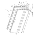
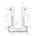
図1、図2に示すように、本実施形態のインクジェットヘッド1は、主走査方向に延在した矩形平面形状を有し且つ用紙に対してインクを吐出する複数のノズル8(図4、図5参照)を備えたヘッド本体70と、このヘッド本体70の上方に配置され且つヘッド本体70に供給されるインクの流路である2つのインク溜まり3が形成されたベースブロック71とを備えている。
As shown in FIGS. 1 and 2, the
ヘッド本体70は、インク流路が形成された流路ユニット4と、流路ユニット4の上面に接着された複数のアクチュエータユニット21とを含んでいる。これら流路ユニット4及びアクチュエータユニット21は、積層された複数の薄板が互いに接着された構成となっている。また、アクチュエータユニット21の上面には、フレキシブルプリント配線板(FPC:Flexible Printed Circuit)50 が接着され、左右に引き出されている。ベースブロック71は、例えばステンレスなどの金属材料からなる。ベースブロック71内のインク溜まり3は、ベースブロック71の長手方向に沿って形成された略直方体の中空領域である。
The
図2に示すように、ベースブロック71の下面73は、開口3bの近傍において周囲よりも下方に飛び出している。そして、ベースブロック71は、下面73の開口3bの近傍部分73aにおいてのみ流路ユニット4と接触している。そのため、ベースブロック71の下面73の開口3bの近傍部分73a以外の領域はヘッド本体70から離隔しており、その間の空間にアクチュエータユニット21が配設されている。
As shown in FIG. 2, the
ベースブロック71は、ホルダ72の把持部72aの下面に形成された凹部内に接着固定されている。ホルダ72は、把持部72aと、把持部72aの上面からこれと直交する方向に所定間隔をなして延出された平板状の一対の突出部72bとを有する。また、アクチュエータユニット21の表面に接着されたFPC50は、スポンジなどの弾性部材83を介してホルダ72の突出部72b表面に沿うように配置されて、その端部が基板81に接続されている。また、ホルダ72の突出部72b表面に配置されたFPC50上にドライバIC80が設置されており、FPC50は、ドライバIC80から出力された駆動信号をヘッド本体70のアクチュエータユニット21(後に詳述)に伝達するように、ドライバIC80及びアクチュエータユニット21に夫々電気的に接続されている。
The
ドライバIC80の外側には略直方体形状のヒートシンク82がドライバIC80に密着した状態で配置されており、このヒートシンク82を介してドライバIC80で発生した熱が外部に放散される。ヒートシンク82の上面と基板81との間、及び、ヒートシンク82の下面とFPC50との間には、夫々シール部材84が装着されている。
A substantially rectangular
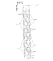
図3は、図1に示したヘッド本体70の平面図である。尚、図3においては、ベースブロック71内に形成されたインク溜まり3が仮想的に破線で描かれている。2つのインク溜まり3は、ヘッド本体70の長手方向に沿って、互いに所定間隔をあけて平行に延在している。2つのインク溜まり3の一端には夫々開口3aが形成され、この開口3aを介してインク溜まり3がインクタンク(図示省略)と連通しており、常にインクで満たされた状態となっている。また、各インク溜まり3には、ヘッド本体70の長手方向に沿って多数の開口3bが設けられており、これら開口3bにより各インク溜まり3と流路ユニット4とが接続されている。多数の開口3bは、対となる2つずつがヘッド本体70の長手方向に沿って近接配置されている。一方のインク溜まり3に連通した開口3bの対と、他方のインク溜まり3に連通した開口3bの対とは、平面視で千鳥状に配置されている。
FIG. 3 is a plan view of the head
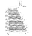
開口3bが配置されていない領域には、台形の平面形状を有する複数のアクチュエータユニット21が、開口3bの対とは逆のパターンで、平面視で千鳥状に配置されている。各アクチュエータユニット21の平行対向辺(台形の平行な2辺)は、ヘッド本体70の長手方向と平行である。また、隣接するアクチュエータユニット21の斜辺は、主走査方向から見て部分的に重なっている。
In a region where the
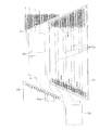
図4は、図3内に描かれた一点鎖線で囲まれた領域の拡大図である。図4に示すように、各インク溜まり3に設けられた開口3bはマニホールド5に連通し、さらに各マニホールド5の先端部は2つに分岐して共通インク室としての副マニホールド5aを形成している。また、平面視において、アクチュエータユニット21における2つの斜辺に夫々隣接する開口3bから、分岐した2つの副マニホールド5aが延出している。つまり、アクチュエータユニット21の下方には、アクチュエータユニット21の平行対向辺に沿って互いに離隔した計4つの副マニホールド5aが延在している。
FIG. 4 is an enlarged view of a region surrounded by a one-dot chain line drawn in FIG. As shown in FIG. 4, the
アクチュエータユニット21の接着領域と反対側の流路ユニット4の下面は、インク吐出領域となっており、このインク吐出領域には、後述するように、多数のノズル8がマトリクス状に配列されている。尚、図4においては、図面を簡略化するためにノズル8のうちの一部のみが描かれているが、実際には、ノズル8はインク吐出領域全体に配列されている。
The lower surface of the
図5は、図4に描かれた一点鎖線で囲まれた領域の拡大図である。図4及び図5は、流路ユニット4における多数の圧力室10がマトリクス状に配置された平面を、インク吐出面に対して垂直な方向から見た状態を示している。各圧力室10は、角部にアールが施された略菱形の平面形状を有し、その長い方の対角線は流路ユニット4の幅方向に平行である。図6に示すように、各圧力室10の一端はノズル8に連通しており、他端はアパーチャ12を介して共通インク流路としての副マニホールド5aに連通している。平面視において各圧力室10と重なり合う位置には、圧力室10と相似でこれよりも一回り小さい平面形状を有する個別電極35が、アクチュエータユニット21上に形成されている。尚、図面を簡略化するために、図5においては多数の個別電極35のうちの一部だけが描かれている。さらに、図4及び図5においては、アクチュエータユニット21内又は流路ユニット4内にあって破線で描かれるべき圧力室10及びアパーチャ12等が実線で描かれている。
FIG. 5 is an enlarged view of a region surrounded by a dashed line drawn in FIG. 4 and 5 show a state where a plurality of
図5において、圧力室10(10a、10b、10c、10d)がそれぞれ収容された仮想的な複数の菱形領域10xは、互いに重なり合うことなく各辺を共有するように、配列方向A及び配列方向Bの2方向にマトリクス状に隣接配置されている。配列方向Aは、インクジェットヘッド1の長手方向、即ち、副マニホールド5aの延在方向であって、菱形領域10xの短い方の対角線と平行である。配列方向Bは、配列方向Aと鈍角θをなす菱形領域10xの一斜辺方向である。圧力室10は、対応する菱形領域10xと中心位置が共通であって、両者の輪郭線は平面視において互いに離隔している。
In FIG. 5, the plurality of
配列方向A及び配列方向Bの2方向にマトリクス状に隣接配置された圧力室10は、配列方向Aに沿って37.5dpiに相当する距離ずつ離隔している。また、圧力室10は、1つのインク吐出領域内において、配列方向Bに16個並べられている。配列方向Bの両端にある圧力室はダミーであって、インク吐出に寄与しない。
The
マトリクス状に配置された複数の圧力室10は、図5に示す配列方向Aに沿って、複数の圧力室列を形成している。圧力室列は、図5の紙面に対して垂直な方向から見て、副マニホールド5aとの相対位置に応じて、第1の圧力室列11a、第2の圧力室列11b、第3の圧力室列11c、及び、第4の圧力室列11dに分けられる。これら第1〜第4の圧力室列11a〜11dは、アクチュエータユニット21の上辺から下辺に向けて、11c→11d→11a→11b→11c→11d→…→11bという順番で周期的に4個ずつ配置されている。
The plurality of
第1の圧力室列11aを構成する圧力室10a及び第2の圧力室列11bを構成する圧力室10bにおいては、図5の紙面に対して垂直な方向から見て、配列方向Aと直交する方向に関して、ノズル8が図5の紙面下側に偏在している。そして、ノズル8が、それぞれ対応する菱形領域10xの下端部に位置している。一方、第3の圧力室列11cを構成する圧力室10c及び第4の圧力室列11dを構成する圧力室10dにおいては、第4の方向に関して、ノズル8が図5の紙面上側に偏在している。そして、ノズル8が、それぞれ対応する菱形領域10xの上端部に位置している。第1及び第4の圧力室列11a、11dにおいては、図5の紙面に対して垂直な方向から見て、圧力室10a、10dの半分以上の領域が、副マニホールド5aと重なっている。第2及び第3の圧力室列11b、11cにおいては、圧力室10b、10cの全領域が、副マニホールド5aと重なっていない。そのため、いずれの圧力室列に属する圧力室10についてもこれに連通するノズル8が副マニホールド5aと重ならないようにしつつ、副マニホールド5aの幅が可能な限り広く形成されており、各圧力室10にインクを円滑に供給することが可能となっている。
In the
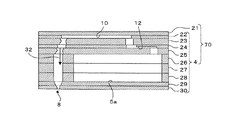
次に、ヘッド本体70の断面構造について、図6及び図7を参照して説明する。図6に示すように、各ノズル8は、圧力室10及びアパーチャ12を介して副マニホールド5aと連通している。このようにして、ヘッド本体70には、副マニホールド5aの出口からアパーチャ12、圧力室10を経てノズル8に至る個別インク流路32が圧力室10ごとに形成されている。
Next, a cross-sectional structure of the
図6に示すように、複数の薄板の積層方向において、圧力室10とアパーチャ12とは異なる深さに設けられている。これにより、図5に示すように、アクチュエータユニット21の下方にあるインク吐出領域に対応した流路ユニット4内において、1つの圧力室10と連通したアパーチャ12を、当該圧力室に隣接する圧力室10と平面視で同じ位置に重ねて配置することが可能となっている。その結果、圧力室10同士が密着して高密度に配列されるため、インク吐出領域の面積が比較的小さなインクジェットヘッド1により高解像度の画像印刷を実現できる。
As shown in FIG. 6, the
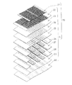
図7に示すように、ヘッド本体70は、上から、アクチュエータユニット21、キャビティプレート22、ベースプレート23、アパーチャプレート24、サプライプレート25、マニホールドプレート26、27、28、カバープレート29及びノズルプレート30の合計10枚のプレートが積層された積層構造を有している。これらのうち、アクチュエータユニット21を除いた9枚のプレートから流路ユニット4が構成されている。
As shown in FIG. 7, the head
アクチュエータユニット21は、後で詳述するように、4枚の圧電シート41〜44(図8(a)参照)が積層され且つ電極が配されることによって、圧電シート41〜44の最上層だけが電界印加時に活性層となる部分を有する層(以下、単に「活性層を有する層」という)となり、一方、残り3層が非活性層となるように構成されている。キャビティプレート22は、圧力室10を形成する平面視で略菱形の開口が多数設けられた金属プレートである。ベースプレート23は、キャビティプレート22の1つの圧力室10について、圧力室10とアパーチャ12との連絡孔及び圧力室10からノズル8への連絡孔がそれぞれ設けられた金属プレートである。アパーチャプレート24は、キャビティプレート22の1つの圧力室10について、2つの孔及びその間を結ぶハーフエッチング領域で形成されたアパーチャ12と、圧力室10からノズル8への連絡孔がそれぞれ設けられた金属プレートである。サプライプレート25は、キャビティプレート22の1つの圧力室10について、アパーチャ12と副マニホールド5aとの連絡孔及び圧力室10からノズル8への連絡孔がそれぞれ設けられた金属プレートである。マニホールドプレート26、27、28は、副マニホールド5aに加えて、キャビティプレート22の1つの圧力室10について、圧力室10からノズル8への連絡孔がそれぞれ設けられた金属プレートである。カバープレート29は、キャビティプレート22の1つの圧力室10について、圧力室10からノズル8への連絡孔がそれぞれ設けられた金属プレートである。ノズルプレート30は、キャビティプレート22の1つの圧力室10について、ノズル8がそれぞれ設けられた金属プレートである。
As will be described later in detail, the
これら10枚のシート21〜30は、図6に示す個別インク流路32が形成されるように、互いに位置合わせして積層されている。この個別インク流路32は、副マニホールド5aからまず上方へ向かい、アパーチャ12において水平に延在し、それからさらに上方に向かい、圧力室10において再び水平に延在し、それからしばらくアパーチャ12から離れる方向に斜め下方に向かってから垂直下方にノズル8へと向かうように形成されている。
These ten
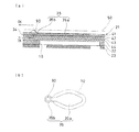
次に、流路ユニット4の最上層のキャビティプレート22に積層された、アクチュエータユニット21の構成について説明する。図8(a)はアクチュエータユニット21と圧力室10との部分拡大断面図であり、図8(b)はアクチュエータユニット21の表面に形成された個別電極35の平面図である。
Next, the configuration of the
図8(a)に示すように、アクチュエータユニット21は、厚みが15μm程度の4枚の圧電シート41、42、43、44を有する。そして、これら4枚の圧電シート41〜44は、ヘッド本体70内の1つのインク吐出領域内に形成された多数の圧力室10に跨って連続して配置された層状の平板(連続平板層)となっている。圧電シート41〜44が連続平板層として多数の圧力室10に跨って配置されることで、例えばスクリーン印刷技術を用いることにより圧電シート41上に次述の個別電極35を高密度に配置することが可能となっている。また、個別電極35に対応する位置に形成される圧力室10をも高密度に配置することが可能であり、高解像度画像の印刷ができるようになる。圧電シート41〜44は、強誘電性を有するチタン酸ジルコン酸鉛(PZT)系のセラミックス材料からなるものである。
As shown in FIG. 8A, the
最上層の圧電シート41上には、個別電極35が形成されている。さらに、最上層の圧電シート41とその下側の圧電シート42との間には、シート全面に形成された略2μmの厚みの共通電極34が介在している。これら個別電極35及び共通電極34は共に、例えばAg−Pd系などの金属材料からなる。
On the uppermost
個別電極35は、略1μmの厚みで圧電シート41上に形成され、個別電極35は、圧力室10とほぼ相似の略菱形の平面形状を有する主電極部35aと、この略菱形の主電極部35aの鋭角部の一方から引き出され、略160μmの径を有する平面視で円形のランド部35bとを有する。図8(b)に示すように、圧電シート41の表面において、主電極部35aは、平面視で圧力室10と重なる領域に設けられ、一方、ランド部35bは、主電極部35aから平面視で圧力室10と重ならない領域まで引き出されている。ランド部35bは、例えばガラスフリットを含む金からなる。また、個別電極35のランド部35bの表面には、Agを含む金属材料からなり導電性を有するバンプ90が上方突出状に形成されている。そして、後述するように、バンプ90を介してFPC35の端子部53(図9参照)が個別電極35に電気的に接続される。尚、本実施形態では、バンプ90は略半球状に形成されており、その高さは35μm程度となっている。
The
共通電極34は、図示しない領域において接地されており、共通電極34は、全ての圧力室10に対向する領域において等しくグランド電位に保たれている。また、個別電極35は、各圧力室10に対応するものごとに電位を制御することができるように、各個別電極35ごとに独立した導体部を有する次述のFPC50を介してドライバIC80に接続されている(図1及び図2参照)。
The
次に、アクチュエータユニット21の複数の個別電極35とドライバIC80とを電気的に接続するFPC50について説明する。
Next, the
図9に示すように、FPC50は、ポリイミドフィルムからなるベース材51と、このベース材51の下側の面に銅箔等の導電性金属により形成された複数の導体部52(配線部分)とを有する。そして、複数の導体部52により、ドライバIC80(図1、図2参照)と複数の個別電極35の各々とを個別に接続する配線パターンが形成されている。また、各導体部52の末端部には、端子部53が設けられ、銅箔の端子部53の表面は半田等の導電性ろう材からなる接合材54で覆われている。
As shown in FIG. 9, the
さらに、FPC50の下面側には、エポキシ樹脂等の熱硬化性樹脂により、端子部53を含む導体部52を覆う電気絶縁性の合成樹脂層55が塗布されている。そして、この合成樹脂層55を、個別電極35のランド部35bに設けられた複数のバンプ90が貫通しており、接合材54を介してバンプ90が導体部52末端の端子部53に接合されている。つまり、バンプ90を介して、FPC50の導体部52と個別電極35とが電気的に接続されている。また、バンプ90と端子部53との接続部においては、合成樹脂層55がアクチュエータユニット21の表面まで達して、合成樹脂層55がFPC50とアクチュエータユニット21とに亙って形成されており、その接続部の強度がより高いものとなっている。
Further, an electrically insulating
次に、アクチュエータユニット21の作用について述べる。アクチュエータユニット21の最上層の圧電シート41の分極方向はその厚み方向であり、アクチュエータユニット21は、上側(つまり、圧力室10とは離れた)1枚の圧電シート41を活性層が存在する層とし且つ下側(つまり、圧力室10に近い)3枚の圧電シート42〜44を非活性層とした、いわゆるユニモルフタイプの構成となっている。従って、個別電極35に正又は負の所定電圧を印加すると、例えば電界と分極とが同方向であれば圧電シート41中の電極に挟まれた電界印加部分が活性層として働き、圧電横効果により分極方向と直角方向に縮む。一方、圧電シート42〜44は、電界の影響を受けないため自発的には縮まないので、上層の圧電シート41と下層の圧電シート42〜44との間で、分極方向と垂直な方向への歪みに差を生じることとなり、圧電シート41〜44全体が非活性側に凸となるように変形しようとする(ユニモルフ変形)。このとき、図8(a)に示したように、圧電シート41〜44の下面は、キャビティプレート22に形成された、圧力室10を区画する隔壁の上面に固定されているので、結果的に圧電シート41〜44は圧力室10側へ凸になるように変形する。このため、圧力室10の容積が低下して、インクの圧力が上昇し、ノズル8からインクが吐出される。その後、個別電極35を共通電極34と同じ電位に戻すと、圧電シート41〜44は元の形状になって圧力室10の容積が元の容積に戻るので、インクをマニホールド5側から吸い込む。
Next, the operation of the
また、他の駆動方法として、予め個別電極35を共通電極34と異なる電位にしておき、吐出要求があるごとに個別電極35を共通電極34と一旦同じ電位とし、その後所定のタイミングにて再び個別電極35を共通電極34と異なる電位にすることもできる。この場合は、個別電極35と共通電極34とが同じ電位になるタイミングで、圧電シート41〜44が元の形状に戻ることにより、圧力室10の容積は初期状態(両電極の電位が異なる状態)と比較して増加し、インクがマニホールド5側から圧力室10内に吸い込まれる。その後再び個別電極35を共通電極34と異なる電位にしたタイミングで、圧電シート41〜44が圧力室10側へ凸となるように変形し、圧力室10の容積低下によりインクへの圧力が上昇し、インクが吐出される。
As another driving method, the
次に、このインクジェットヘッド1の製造方法について説明する。まず、キャビティプレート22、ベースプレート23、アパーチャプレート24、サプライプレート25、マニホールドプレート26、27、28、カバープレート29及びノズルプレート30の9枚のプレート22〜30を、その内部に個別インク流路32が形成される状態に積層して接着剤により接合し、流路ユニット4を作製する。
Next, a method for manufacturing the
次に、アクチュエータユニット21を以下のような工程で作製する。まず、チタン酸ジルコン酸鉛(PZT)系のセラミック粉末、バインダ及び溶剤を混合して、PET(ポリエチレンテレフタレート)等の樹脂フィルム上に広げて乾燥させたグリーンシートを形成する。このグリーンシートは、1枚で複数のアクチュエータユニット21の圧電シートを形成することができる、比較的大判のものである。
Next, the
そして、圧電シート41となるグリーンシートの表面に、導電性ペーストを印刷して複数の個別電極35を形成する。また、圧電シート42となるグリーンシートの表面に、導電性ペーストを印刷して共通電極34を形成する。そして、4枚の圧電シート41〜44となる4枚のグリーンシートを積層方向に加圧して一体化させた後、この大判のグリーンシートの積層体から、1つのインクジェットヘッド1に対応するアクチュエータユニット21に対応する領域を切り出し、切り出されたグリーンシートの積層体を焼成する。
Then, a conductive paste is printed on the surface of the green sheet to be the
そして、流路ユニット4(キャビティプレート22)の表面に接着剤を塗布して、アクチュエータユニット21を流路ユニット4に接着する。
Then, an adhesive is applied to the surface of the flow path unit 4 (cavity plate 22) to bond the
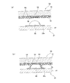
次に、図10(a)に示すように、圧電シート41の上面に、平面視で圧力室10に重ならない領域に形成された複数の個別電極35のランド部35bを、多数の孔を有するメタルマスクで覆った状態で、Agを含む導電性ペーストを印刷することにより、複数のランド部35bに、略半球状に突出する複数のバンプ90を夫々形成する(第1工程)。
Next, as shown in FIG. 10 (a),
一方、FPC50の端子部53の表面に半田等の導電性ろう材からなる接合材54の層を形成してから、FPC50の下面全体に未硬化の熱硬化性樹脂を印刷等の方法により塗布し、導体部52の全体を覆う未硬化の合成樹脂層55を形成する(第2工程)。尚、このとき、温度等の諸条件を適切に調整して、合成樹脂層55をFPC50から垂れ落ちない程度の未硬化(半硬化)の状態に維持しておく。
On the other hand, after a layer of a
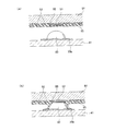
次に、図10(b)に示すように、バンプ90に対するFPC50の端子部53の位置を合わせてから、FPC50を圧電シート41側に押しつけることにより、未硬化の合成樹脂層55に複数のバンプ90を押し当てて合成樹脂層55を貫通させ、複数のバンプ90の先端と端子部53表面の接合材54とを接触させる(第3工程)。このとき、端子部53に接触したバンプ90の表面が未硬化の合成樹脂により覆われることになる。ここで、合成樹脂層55は未硬化の状態であるため、バンプ90の形状が尖鋭な形状でない半球状であっても、バンプ90が容易に合成樹脂層55を貫通することができる。さらに、合成樹脂層55の厚さや硬化度合等の条件を適宜設定することにより、合成樹脂層55にバンプ90を貫通させたときに、図10(b)に示すように、バンプ90の表面を覆う未硬化の合成樹脂がランド部35b(アクチュエータユニット21)の表面にまで達することが好ましい。
Next, as shown in FIG. 10B, after aligning the position of the
尚、本実施形態においては、導体部52の厚さは9μm程度である。一方、導体部52を覆う合成樹脂層55は15〜20μm程度であり、合成樹脂層55により導体部52が確実に被覆されるとともに、合成樹脂層55にバンプ90を貫通させた状態では未硬化の合成樹脂がランド部35bの表面にまで達する厚さとなっている。また、本実施形態では、合成樹脂層55が未硬化状態であり、バンプ90を端子部53に接触させる際にバンプ90が合成樹脂層55を貫通しやすくなっているため、バンプ90は略半球状に形成されている。しかし、バンプ90が合成樹脂層55を貫通した上で、バンプ90と端子部53との、より確実な電気的導通を確保するという観点からは、バンプ90の先端形状は尖鋭な形状に形成されることが好ましい。
In the present embodiment, the thickness of the
次に、熱硬化性樹脂である未硬化の合成樹脂層55を加熱して(例えば、150℃)、合成樹脂層55を硬化させる(第4工程)。さらに加熱することにより(例えば、240℃)接合材54を溶融させ、バンプ90と端子部53とを接合材54により接合する。このように、バンプ90を覆う合成樹脂層55を硬化させ、さらに、バンプ90と端子部53とを接合材54を用いて接合させることにより、FPC50の端子部53と個別電極35側のバンプ90との接合強度が高くなる。また、前述のように、バンプ90の表面を覆う未硬化の合成樹脂がランド部35bの表面にまで達している場合には、FPC50の端子部53と個別電極35側のバンプ90との接合強度が高まり、その電気的接続の信頼性がより向上する。さらに、合成樹脂層55が、バンプ90と端子部53との接触部分を含んだ状態でバンプ90を覆うため、端子部53の上に形成されている接合材54が溶融しても、隣接する導体部53との電気的絶縁性が十分に確保される。
Next, the uncured
以上説明したインクジェットヘッド1の製造方法では、FPC50に未硬化の合成樹脂層55を塗布により形成してから、アクチュエータユニット21側のバンプ90を押しつけて合成樹脂層55を貫通させることにより、導体部52を合成樹脂層55により確実に絶縁しつつ、バンプ90と端子部53とを容易に接触させることができる。そのため、従来の製造方法(図12参照)のように、FPC50側に絶縁用のカバーコートが不要となり、さらに、導体部52の端子部35を露出させるために端子部35付近のカバーコートを高精度に開口させる工程も不要となり、FPC50の製造コストを低減できる。また、アクチュエータユニット21側にバンプ90を設けるため、FPC50の端子部53の大きさは、バンプ90の先端が確実に接触することのできる大きさがあれば十分であることから、カバーコートの開口精度等を勘案して端子部53を大き目に形成する必要のある、FPC50側にバンプ90を設ける従来の製造方法(図12参照)と比較して、端子部53の大きさ(図9のA1)を小さくすることができ、その分、FPC50の配線密度を粗くすることが可能になる。さらに、合成樹脂層55が未硬化の状態で、合成樹脂層55にバンプ90を押し当てるため、合成樹脂層55を貫通させるためにバンプ90の先端を尖鋭な形状にする必要がなく、バンプ90の形成が容易である。
In the method of manufacturing the
また、前述したように、FPC50の端子部53と個別電極35とを電気的に接続するバンプ90は、平面視で圧力室10と重なる領域に設けられた主電極部35a上ではなく、主電極部35aから平面視で圧力室10と重ならない領域まで引き出されたランド部35b上に設けられている。そのため、バンプ90と端子部53とを接合したときに、溶融した接合材54や未硬化の熱硬化性樹脂がランド部35bの表面に付着した状態でも、ドライバIC80からFPC50及びバンプ90を介してランド部35bに駆動信号が入力されたときに、圧電シート41〜44の、圧力室10に対向する部分の変形が阻害されることがなく、インクを安定して吐出することが可能になる。
Further, as described above, the
次に、前記実施形態に種々の変更を加えた変更形態について説明する。但し、前記実施形態と同様の構成を有するものについては、同じ符号を付して適宜その説明を省略する。 Next, modified embodiments in which various modifications are made to the embodiment will be described. However, components having the same configuration as in the above embodiment are given the same reference numerals and description thereof is omitted as appropriate.
1]前記実施形態では、熱硬化性樹脂を硬化させた後に、接合材54を溶融させてバンプ90と端子部53とを接合するようにしているが、別の硬化温度の熱硬化性樹脂や、別の溶融温度の接合材を適宜選択することにより、接合材54を溶融させてバンプ90と端子部53とを接合してから、合成樹脂層55を硬化させるようにしてもよい。
1] In the above-described embodiment, after the thermosetting resin is cured, the
2]前記実施形態のように、接合材54を用いてバンプ90と端子部53とを接合する場合には、その接合だけで比較的高い接合強度を確保できるため、バンプ90により合成樹脂層55を貫通させたときに、未硬化の合成樹脂層55がランド部35b(アクチュエータユニット21の表面)に達して、合成樹脂層55がFPC50とアクチュエータユニット21に亙って形成される必要は必ずしもない。即ち、合成樹脂層55がバンプ90の表面を部分的にしか覆っていない状態で合成樹脂層55を硬化させてもよい。
2] When the
3]バンプ90と端子部53とを接合する必要は必ずしもなく、バンプ90と端子部53が単に接触しているだけの状態で、合成樹脂層55を硬化させることにより、バンプ90と端子部53との電気的接続を完了するようにしてもよい。また、この場合、銅箔等からなる端子部53の表面に酸化膜が形成されて、端子部53とバンプ90の電気的接続の信頼性が低下するのを防止するために、端子部53の表面にAu等の酸化防止層を形成してもよい。尚、このように、バンプ90と端子部53と接合材を用いて接合しない場合には、バンプ90と端子部53との間の接続強度を高めるために、前記実施形態の図10(b)に示すように、未硬化の合成樹脂層55がランド部35b(アクチュエータユニット21の表面)に達して、合成樹脂層55がFPC50とアクチュエータユニット21に亙って形成されていることが特に好ましい。
3] It is not always necessary to join the
4]図11(a)に示すように、少なくとも端子部53の表面にSnの層95を形成し、Agを含むバンプ90と端子部53側のSn層95とを接触させた状態で所定温度まで加熱することにより、図11(b)に示すように、端子部53とバンプ90との間に、Ag−Snの金属接合層96を形成するようにしてもよい。ここで、このAgとSnという組み合わせにおける溶融開始の温度は約230℃であるので、例えば、接合時の作業温度を240℃に設定して接合層を形成する。この場合には、端子部53とバンプ90との間の接続強度が高まり、電気的接続の信頼性が向上する。
4] As shown in FIG. 11A, an
5]複数のバンプを、Agを含む導電性且つ熱硬化性を有する接着材で形成してもよい。この場合、半硬化状態のバンプで合成樹脂層55を貫通させて、バンプを端子部53に接触させてから、バンプを加熱して硬化させることにより、FPC50の端子部53と個別電極35のランド部35bとを接着するため、FPC50と個別電極35の電気的接続の信頼性がより高くなる。
5] A plurality of bumps may be formed of a conductive and thermosetting adhesive containing Ag. In this case, the
6]前記実施形態においては、大判のグリーンシートの積層体から、1つのインクジェットヘッド1に対応するアクチュエータユニット21に対応する領域を切り出し、切り出されたグリーンシートの積層体を焼成した後に、個別電極35のランド部35bの表面にバンプ90を印刷しているが、大判のグリーンシートの積層体の状態で、ランド部35bの表面にバンプ90を印刷してもよい。
6] In the above-described embodiment, after the region corresponding to the
7]未硬化の合成樹脂としては、前記実施形態のエポキシ樹脂等の熱硬化性樹脂の他、照射された紫外線により硬化する紫外線硬化性樹脂など、種々の合成樹脂を用いることができる。 7] As the uncured synthetic resin, various synthetic resins such as an ultraviolet curable resin that is cured by irradiated ultraviolet rays can be used in addition to the thermosetting resin such as the epoxy resin of the embodiment.
8]前記実施形態は、アクチュエータユニット21に可撓性を有するFPC50を接続する場合に本発明を適用した一例であるが、アクチュエータユニット21にプリント配線板を接続する場合にも本発明を適用できる。
8] The above embodiment is an example in which the present invention is applied when the
9]本発明は、例えば、サーマルプリンタやドットプリンタ等のインクジェットヘッド以外の他の記録ヘッドにも適用可能である。 9] The present invention can also be applied to recording heads other than inkjet heads such as thermal printers and dot printers.
1 インクジェットヘッド
4 流路ユニット
8 ノズル
10 圧力室
41〜44 圧電シート
21 アクチュエータユニット
35a 主電極部
35b ランド部
35 個別電極
35 端子部
50 フレキシブルプリント配線板
52 導体部
53 端子部
54 接合材
55 合成樹脂層
90 バンプ
DESCRIPTION OF
Claims (9)
前記アクチュエータユニットの表面に、前記複数の個別電極と夫々電気的に接続された導電性の複数のバンプを突出状に形成する第1工程と、
前記プリント配線板の配線部分を覆う未硬化の合成樹脂層を塗布する第2工程と、
前記プリント配線板に塗布された前記未硬化の合成樹脂層に前記複数のバンプを押し当ててこの合成樹脂層を貫通させ、前記複数のバンプと前記配線部分の端子部とを接触させる第3工程と、
前記合成樹脂層を硬化させる第4工程と、
を備えたことを特徴とする記録ヘッドの製造方法。 An actuator unit having a plurality of individual electrodes respectively corresponding to a plurality of recording elements; a printed wiring board electrically connected to the plurality of individual electrodes and supplying a signal for driving the recording elements to the individual electrodes; A method for manufacturing a recording head comprising:
A first step of projecting a plurality of conductive bumps electrically connected to the plurality of individual electrodes on the surface of the actuator unit;
A second step of applying an uncured synthetic resin layer covering the wiring portion of the printed wiring board;
A third step of pressing the plurality of bumps against the uncured synthetic resin layer applied to the printed wiring board to penetrate the synthetic resin layer and bringing the plurality of bumps into contact with the terminal portions of the wiring portion When,
A fourth step of curing the synthetic resin layer;
A method for manufacturing a recording head, comprising:
前記アクチュエータユニットは、前記流路ユニットの表面に設けられて前記圧力室の容積を変化させる圧電シートと、前記圧電シートの表面に前記複数の圧力室に夫々対応して形成された複数の個別電極とを有し、
前記個別電極は、前記圧電シートに垂直な方向から見て、前記圧電シートの表面の前記圧力室に重なる領域に形成された主電極部と、前記圧電シートに垂直な方向から見て、前記主電極部から前記圧力室に重ならない領域まで引き出されたランド部とを有し、
前記第1工程において、前記バンプを前記ランド部の表面に形成することを特徴とする請求項1〜6の何れかに記載の記録ヘッドの製造方法。 The recording head is an inkjet head including a flow path unit having a plurality of pressure chambers communicating with nozzles for ejecting ink and a common ink chamber communicating with the plurality of pressure chambers.
The actuator unit includes a piezoelectric sheet that is provided on a surface of the flow path unit and changes a volume of the pressure chamber, and a plurality of individual electrodes that are formed on the surface of the piezoelectric sheet so as to correspond to the plurality of pressure chambers, respectively. And
The individual electrode includes a main electrode portion formed in a region overlapping the pressure chamber on the surface of the piezoelectric sheet as viewed from a direction perpendicular to the piezoelectric sheet, and the main electrode portion as viewed from a direction perpendicular to the piezoelectric sheet. A land portion led out from the electrode portion to a region not overlapping the pressure chamber,
The method for manufacturing a recording head according to claim 1, wherein the bump is formed on a surface of the land portion in the first step.
前記アクチュエータユニットの表面に、前記複数の個別電極と夫々電気的に接続された導電性の複数のバンプが突出状に形成され、
前記プリント配線板に、その配線部分を覆う合成樹脂層が形成され、
前記複数のバンプが、前記プリント配線板に形成された前記合成樹脂層を貫通して前記配線部分の端子部に電気的に接続されていることを特徴とする記録ヘッド。 An actuator unit having a plurality of individual electrodes respectively corresponding to a plurality of recording elements, and a printed wiring board that is electrically connected to the plurality of individual electrodes and supplies a signal for driving the recording elements to the individual electrodes And
On the surface of the actuator unit, a plurality of conductive bumps electrically connected to the plurality of individual electrodes are formed in a protruding shape,
A synthetic resin layer covering the wiring portion is formed on the printed wiring board,
The recording head, wherein the plurality of bumps penetrate the synthetic resin layer formed on the printed wiring board and are electrically connected to a terminal portion of the wiring portion.
Priority Applications (1)
| Application Number | Priority Date | Filing Date | Title |
|---|---|---|---|
| JP2008305967A JP4618368B2 (en) | 2008-12-01 | 2008-12-01 | Recording head manufacturing method and recording head |
Applications Claiming Priority (1)
| Application Number | Priority Date | Filing Date | Title |
|---|---|---|---|
| JP2008305967A JP4618368B2 (en) | 2008-12-01 | 2008-12-01 | Recording head manufacturing method and recording head |
Related Parent Applications (1)
| Application Number | Title | Priority Date | Filing Date |
|---|---|---|---|
| JP2004126380A Division JP4281608B2 (en) | 2004-04-22 | 2004-04-22 | Recording head manufacturing method and recording head |
Publications (2)
| Publication Number | Publication Date |
|---|---|
| JP2009078564A true JP2009078564A (en) | 2009-04-16 |
| JP4618368B2 JP4618368B2 (en) | 2011-01-26 |
Family
ID=40653667
Family Applications (1)
| Application Number | Title | Priority Date | Filing Date |
|---|---|---|---|
| JP2008305967A Expired - Fee Related JP4618368B2 (en) | 2008-12-01 | 2008-12-01 | Recording head manufacturing method and recording head |
Country Status (1)
| Country | Link |
|---|---|
| JP (1) | JP4618368B2 (en) |
Cited By (8)
| Publication number | Priority date | Publication date | Assignee | Title |
|---|---|---|---|---|
| EP2327551A1 (en) | 2009-11-30 | 2011-06-01 | Brother Kogyo Kabushiki Kaisha | Piezoelectric actuator, liquid discharge head and method of manufacturing same |
| JP2011121186A (en) * | 2009-12-08 | 2011-06-23 | Brother Industries Ltd | Recording head |
| JP2011218682A (en) * | 2010-04-09 | 2011-11-04 | Konica Minolta Holdings Inc | Ink jet head, method of manufacturing ink jet head, and ink jet drawing device |
| JP2012061697A (en) * | 2010-09-15 | 2012-03-29 | Ricoh Co Ltd | Liquid ejection head, and image forming apparatus |
| US8511798B2 (en) | 2009-09-29 | 2013-08-20 | Brother Kogyo Kabushiki Kaisha | Method of manufacturing liquid discharge head, liquid discharge head and ink-jet printer |
| US9914300B2 (en) | 2015-03-16 | 2018-03-13 | Seiko Epson Corporation | Head and liquid ejecting apparatus with electrically connecting bumps |
| US10207503B2 (en) | 2016-01-20 | 2019-02-19 | Seiko Epson Corporation | MEMS device, liquid ejecting head, liquid ejecting apparatus, and MEMS device manufacturing method |
| JP2019069616A (en) * | 2018-12-25 | 2019-05-09 | ブラザー工業株式会社 | Liquid jet device and piezoelectric actuator |
Citations (3)
| Publication number | Priority date | Publication date | Assignee | Title |
|---|---|---|---|---|
| JPH11254670A (en) * | 1998-03-10 | 1999-09-21 | Nec Corp | Ink jet head |
| JP2002331667A (en) * | 2001-05-09 | 2002-11-19 | Canon Inc | Printhead, method of manufacturing printhead, and inkjet printing apparatus |
| JP2005305847A (en) * | 2004-04-22 | 2005-11-04 | Brother Ind Ltd | Recording head manufacturing method and recording head |
-
2008
- 2008-12-01 JP JP2008305967A patent/JP4618368B2/en not_active Expired - Fee Related
Patent Citations (3)
| Publication number | Priority date | Publication date | Assignee | Title |
|---|---|---|---|---|
| JPH11254670A (en) * | 1998-03-10 | 1999-09-21 | Nec Corp | Ink jet head |
| JP2002331667A (en) * | 2001-05-09 | 2002-11-19 | Canon Inc | Printhead, method of manufacturing printhead, and inkjet printing apparatus |
| JP2005305847A (en) * | 2004-04-22 | 2005-11-04 | Brother Ind Ltd | Recording head manufacturing method and recording head |
Cited By (10)
| Publication number | Priority date | Publication date | Assignee | Title |
|---|---|---|---|---|
| US8511798B2 (en) | 2009-09-29 | 2013-08-20 | Brother Kogyo Kabushiki Kaisha | Method of manufacturing liquid discharge head, liquid discharge head and ink-jet printer |
| EP2327551A1 (en) | 2009-11-30 | 2011-06-01 | Brother Kogyo Kabushiki Kaisha | Piezoelectric actuator, liquid discharge head and method of manufacturing same |
| US8613500B2 (en) | 2009-11-30 | 2013-12-24 | Brother Kogyo Kabushiki Kaisha | Piezoelectric actuator, liquid discharge head, and method of manufacturing same |
| JP2011121186A (en) * | 2009-12-08 | 2011-06-23 | Brother Industries Ltd | Recording head |
| US8944568B2 (en) | 2009-12-08 | 2015-02-03 | Brother Kogyo Kabushiki Kaisha | Printhead and method of manufacturing printhead |
| JP2011218682A (en) * | 2010-04-09 | 2011-11-04 | Konica Minolta Holdings Inc | Ink jet head, method of manufacturing ink jet head, and ink jet drawing device |
| JP2012061697A (en) * | 2010-09-15 | 2012-03-29 | Ricoh Co Ltd | Liquid ejection head, and image forming apparatus |
| US9914300B2 (en) | 2015-03-16 | 2018-03-13 | Seiko Epson Corporation | Head and liquid ejecting apparatus with electrically connecting bumps |
| US10207503B2 (en) | 2016-01-20 | 2019-02-19 | Seiko Epson Corporation | MEMS device, liquid ejecting head, liquid ejecting apparatus, and MEMS device manufacturing method |
| JP2019069616A (en) * | 2018-12-25 | 2019-05-09 | ブラザー工業株式会社 | Liquid jet device and piezoelectric actuator |
Also Published As
| Publication number | Publication date |
|---|---|
| JP4618368B2 (en) | 2011-01-26 |
Similar Documents
| Publication | Publication Date | Title |
|---|---|---|
| JP4179121B2 (en) | Ink jet head and manufacturing method thereof | |
| JP4281608B2 (en) | Recording head manufacturing method and recording head | |
| JP4618368B2 (en) | Recording head manufacturing method and recording head | |
| JP4419754B2 (en) | Inkjet head | |
| JP4134773B2 (en) | Inkjet head | |
| JP4595418B2 (en) | Inkjet head | |
| JP2006103117A (en) | Inkjet head | |
| JP4432924B2 (en) | Ink jet head and manufacturing method thereof | |
| JP2005305982A (en) | Inkjet head | |
| JP4207023B2 (en) | Inkjet head | |
| JP4525094B2 (en) | Inkjet head manufacturing method | |
| JP4329734B2 (en) | Inkjet head | |
| JP4581709B2 (en) | Inkjet head | |
| JP4193684B2 (en) | Inkjet head manufacturing method | |
| JP2006095915A (en) | Inkjet head, relay substrate, composite substrate, inkjet head manufacturing method, and composite substrate manufacturing method | |
| US7571993B2 (en) | Ink-jet head | |
| JP2005280044A (en) | Inkjet head manufacturing method | |
| JP4627655B2 (en) | Ink jet head and manufacturing method thereof | |
| CN101125481B (en) | Ink-jet head and method of producing the same | |
| JP2006116953A (en) | Liquid ejecting apparatus and manufacturing method thereof | |
| JP4603762B2 (en) | Inkjet head manufacturing method | |
| US7249413B2 (en) | Method for manufacturing inkjet printing head | |
| JP2007210114A (en) | Inkjet head | |
| JP2010129873A (en) | Method of connecting wiring member, method of manufacturing the same, and wiring member | |
| JP2006007669A (en) | Printed circuit board manufacturing method, printed circuit board, ink jet head, and ink jet head manufacturing method |
Legal Events
| Date | Code | Title | Description |
|---|---|---|---|
| A131 | Notification of reasons for refusal |
Free format text: JAPANESE INTERMEDIATE CODE: A131 Effective date: 20100309 |
|
| A521 | Written amendment |
Free format text: JAPANESE INTERMEDIATE CODE: A523 Effective date: 20100510 |
|
| RD02 | Notification of acceptance of power of attorney |
Free format text: JAPANESE INTERMEDIATE CODE: A7422 Effective date: 20100510 |
|
| A131 | Notification of reasons for refusal |
Free format text: JAPANESE INTERMEDIATE CODE: A131 Effective date: 20100706 |
|
| A521 | Written amendment |
Free format text: JAPANESE INTERMEDIATE CODE: A523 Effective date: 20100810 |
|
| RD04 | Notification of resignation of power of attorney |
Free format text: JAPANESE INTERMEDIATE CODE: A7424 Effective date: 20100913 |
|
| TRDD | Decision of grant or rejection written | ||
| A01 | Written decision to grant a patent or to grant a registration (utility model) |
Free format text: JAPANESE INTERMEDIATE CODE: A01 Effective date: 20100928 |
|
| A01 | Written decision to grant a patent or to grant a registration (utility model) |
Free format text: JAPANESE INTERMEDIATE CODE: A01 |
|
| A61 | First payment of annual fees (during grant procedure) |
Free format text: JAPANESE INTERMEDIATE CODE: A61 Effective date: 20101011 |
|
| FPAY | Renewal fee payment (event date is renewal date of database) |
Free format text: PAYMENT UNTIL: 20131105 Year of fee payment: 3 |
|
| R150 | Certificate of patent or registration of utility model |
Ref document number: 4618368 Country of ref document: JP Free format text: JAPANESE INTERMEDIATE CODE: R150 Free format text: JAPANESE INTERMEDIATE CODE: R150 |
|
| LAPS | Cancellation because of no payment of annual fees |
