JP2009073224A - Scooter type vehicle - Google Patents
Scooter type vehicle Download PDFInfo
- Publication number
- JP2009073224A JP2009073224A JP2007241647A JP2007241647A JP2009073224A JP 2009073224 A JP2009073224 A JP 2009073224A JP 2007241647 A JP2007241647 A JP 2007241647A JP 2007241647 A JP2007241647 A JP 2007241647A JP 2009073224 A JP2009073224 A JP 2009073224A
- Authority
- JP
- Japan
- Prior art keywords
- wheel
- type vehicle
- scooter type
- fender
- wide
- Prior art date
- Legal status (The legal status is an assumption and is not a legal conclusion. Google has not performed a legal analysis and makes no representation as to the accuracy of the status listed.)
- Pending
Links
Images


Abstract
Description
本発明は、車輪と、車輪の上方に配設されるフェンダーと、ライダーの脚部の前方に配設される車体カバーとを備えるスクータ型車両に関する。 The present invention relates to a scooter type vehicle including a wheel, a fender disposed above the wheel, and a vehicle body cover disposed in front of a rider's leg.
ライダーが両足を載せることができるフートボードを有するスクータ型車両において、不整地などの走行に対応することができるモデルが実現されている(例えば、特許文献1参照)。 In a scooter type vehicle having a footboard on which a rider can put both feet, a model that can cope with traveling on rough terrain has been realized (for example, see Patent Document 1).
このようなスクータ型車両では、前輪が巻き上げた泥などの飛散を防止する大型のフェンダーが前輪の上方に配設される。フェンダーは、フロントフォークの上部、具体的には、アンダーブラケットに固定される。このため、フェンダーの高さは、前輪のストロークによっては変化しない。一方、ハンドルバーが操作されると、フェンダーは、前輪とともに左右に回動する。
しかしながら、上述した従来のスクータ型車両には、次のような問題があった。すなわち、スクータ型車両では、ステアリングヘッドパイプの前方に配設されるフロントカバーや、ライダーの脚部の前方に配設される車体カバー、具体的には、アンダーカウルやレッグシールドを備えるため、前輪が巻き上げた泥などが車体カバーに付着し易いといった問題があった。 However, the conventional scooter type vehicle described above has the following problems. In other words, the scooter type vehicle includes a front cover disposed in front of the steering head pipe, a vehicle body cover disposed in front of the rider's legs, specifically, an under cowl and a leg shield. There is a problem that mud or the like rolled up easily adheres to the body cover.
そこで、本発明は、このような状況に鑑みてなされたものであり、車輪が巻き上げた泥などの飛散をより効果的に防止できるフェンダーを備えたスクータ型車両を提供することを目的とする。 Therefore, the present invention has been made in view of such a situation, and an object of the present invention is to provide a scooter-type vehicle including a fender that can more effectively prevent scattering of mud and the like rolled up by wheels.
上述した問題を解決するため、本発明は、次のような特徴を有している。まず、本発明の第1の特徴は、車輪(前輪20)と、前記車輪の上方に配設され、ハンドル(ハンドル23)の操作に伴って前記車輪とともに回動するフェンダー(フロントフェンダー400)と、前記車輪の後方において、ライダーの脚部の前方に配設される車体カバー(レッグシールド30及びアンダーカウル35)とを備えるスクータ型車両(自動二輪車10)であって、前記フェンダーは、前記スクータ型車両の平面視において、車幅方向に広がった前方幅広部(幅広部410)と、前記スクータ型車両の平面視において、前記前方幅広部よりも幅が狭い幅狭部(幅狭部420)とを有し、前記前方幅広部は、前記幅狭部よりも前方に形成され、前記幅狭部の斜め後方には、前記車体カバーが配設されることを要旨とする。
In order to solve the problems described above, the present invention has the following features. First, the first feature of the present invention is a wheel (front wheel 20), a fender (front fender 400) that is disposed above the wheel and rotates with the wheel in accordance with the operation of the handle (handle 23). A scooter type vehicle (motorcycle 10) including a vehicle body cover (
このようなスクータ型車両によれば、フェンダーには、車幅方向に広がった前方幅広部が設けられる。前方幅広部の後方には、前方幅広部よりも幅が狭い幅狭部が設けられる。また、幅狭部の斜め後方には、ライダーの脚部の前方に配設される車体カバーが配設される。 According to such a scooter type vehicle, the fender is provided with a wide front portion that widens in the vehicle width direction. A narrow part narrower than the front wide part is provided behind the wide front part. A vehicle body cover disposed in front of the rider's legs is disposed obliquely behind the narrow portion.
このため、車輪が巻き上げた泥などが車体カバーなどに付着することを前方幅広部によって効果的に防止できる。また、前方幅広部の後方には幅狭部が設けられるため、車体カバーとの干渉を回避しつつフェンダーの寸法を大型化できる。 For this reason, it can prevent effectively that the mud etc. which the wheel rolled up adheres to a vehicle body cover etc. by the front wide part. In addition, since the narrow portion is provided behind the wide front portion, the size of the fender can be increased while avoiding interference with the vehicle body cover.
本発明の第2の特徴は、本発明の第1の特徴に係り、前記前方幅広部の車幅方向における最大幅部分(最大幅部分411)の寸法(幅W2)は、前記車輪の幅(車輪幅W1)以上であることを要旨とする。 A second feature of the present invention relates to the first feature of the present invention, wherein the dimension (width W2) of the maximum width portion (maximum width portion 411) in the vehicle width direction of the front wide portion is the width of the wheel ( The gist is that the wheel width is W1) or more.
本発明の第3の特徴は、本発明の第1の特徴に係り、前記幅狭部は、前記車輪が前記ハンドルの操作に伴って回動すると、前記車体カバーの外側面(外側面35a)を沿って移動することを要旨とする。
A third feature of the present invention relates to the first feature of the present invention, wherein the narrow portion is configured such that when the wheel rotates in accordance with the operation of the handle, the outer surface (
本発明の第4の特徴は、本発明の第1の特徴に係り、前記車輪を回動可能に支持する一対のフォーク部(フロントフォーク21L,21R)を備え、前記フェンダーは、前記スクータ型車両の平面視において、前記幅狭部よりも車幅方向に広がった後方幅広部(幅広部430)を有し、前記後方幅広部は、前記幅狭部の後方であって、前記フォーク部の前方に形成されることを要旨とする。
A fourth feature of the present invention relates to the first feature of the present invention, and includes a pair of fork portions (
本発明の第5の特徴は、本発明の第1の特徴に係り、前記前方幅広部は、車幅方向における前記フェンダーの中心線(中心線CL)を含む位置に形成される本体部分(本体部分410a)と、前記本体部分から車幅方向外側に向けて突出した突出部分(突出部分410b)とを有し、前記突出部分は、前記スクータ型車両の前後方向に垂直な断面内において、前記本体部分よりも低い位置に形成されることを要旨とする。
A fifth feature of the present invention relates to the first feature of the present invention, wherein the wide front portion is a main body portion (main body) formed at a position including a center line (center line CL) of the fender in the vehicle width direction.
本発明の第6の特徴は、本発明の第1の特徴に係り、前記前方幅広部は、前記スクータ型車両の平面視において、後方に行くに従って幅が広がることを要旨とする。 A sixth feature of the present invention relates to the first feature of the present invention, and is summarized in that the width of the front wide portion increases as it goes rearward in a plan view of the scooter type vehicle.
本発明の第7の特徴は、本発明の第1の特徴に係り、前記車輪を前記スクータ型車両の略上下方向に沿って移動可能に支持する車輪支持部(フロントフォーク21L,21R)を備え、前記フェンダーは、前記スクータ型車両の略上下方向に沿った前記車輪の移動とは独立し、前記ハンドルの操作に伴う前記車輪の回動のみに対して前記車輪とともに回動することを要旨とする。
A seventh feature of the present invention relates to the first feature of the present invention, and includes wheel support portions (
本発明の第8の特徴は、本発明の第1の特徴に係り、前記フェンダーの上方に配設される灯火器(ヘッドライト281)を備え、前記前方幅広部の車幅方向における最大幅部分(最大幅部分411)の寸法(幅W2)は、前記灯火器の車幅方向における最大幅部分の寸法と略同一、または前記灯火器の車幅方向における最大幅部分の寸法(幅W3)よりも大きいことを要旨とする。 An eighth feature of the present invention relates to the first feature of the present invention, and comprises a lighting device (headlight 281) disposed above the fender, wherein the widest portion in the vehicle width direction of the wide front portion. The dimension (width W2) of the (maximum width portion 411) is substantially the same as the dimension of the maximum width portion in the vehicle width direction of the lamp or the dimension (width W3) of the maximum width portion of the lamp in the vehicle width direction. The main point is that it is large.
本発明の第9の特徴は、本発明の第8の特徴に係り、前記灯火器の周囲に配設される前部カバー部(フロントカバー200)を備え、前記前部カバー部の下部には、切欠き部分(切欠き部200b)が形成され、前記灯火器の少なくとも一部は、前記切欠き部分に配設されることを要旨とする。
A ninth feature of the present invention relates to the eighth feature of the present invention, and is provided with a front cover portion (front cover 200) disposed around the lighting device, at a lower portion of the front cover portion. A notch portion (
本発明の特徴によれば、車輪が巻き上げた泥などの飛散をより効果的に防止できるフェンダーを備えたスクータ型車両を提供することができる。 According to the characteristics of the present invention, it is possible to provide a scooter-type vehicle including a fender that can more effectively prevent the scattering of mud and the like rolled up by wheels.
次に、本発明に係るスクータ型車両の実施形態について、図面を参照しながら説明する。具体的には、(1)スクータ型車両の全体概略構成、(2)フェンダーの形状、(3)フェンダーの取付状態、(4)作用・効果及び(5)その他の実施形態について説明する。 Next, an embodiment of a scooter type vehicle according to the present invention will be described with reference to the drawings. Specifically, (1) the overall schematic configuration of the scooter type vehicle, (2) the shape of the fender, (3) the mounting state of the fender, (4) actions and effects, and (5) other embodiments will be described.
なお、以下の図面の記載において、同一または類似の部分には、同一または類似の符号を付している。ただし、図面は模式的なものであり、各寸法の比率などは現実のものとは異なることに留意すべきである。 In the following description of the drawings, the same or similar parts are denoted by the same or similar reference numerals. However, it should be noted that the drawings are schematic and ratios of dimensions and the like are different from actual ones.
したがって、具体的な寸法などは以下の説明を参酌して判断すべきものである。また、図面相互間においても互いの寸法の関係や比率が異なる部分が含まれていることは勿論である。 Accordingly, specific dimensions and the like should be determined in consideration of the following description. Moreover, it is a matter of course that portions having different dimensional relationships and ratios are included between the drawings.
(1)スクータ型車両の全体概略構成
図1は、本実施形態においてスクータ型車両を構成する自動二輪車10の左側面図である。図2は、自動二輪車10の斜視図である。図3は、自動二輪車10の正面図である。
(1) Overall Schematic Configuration of Scooter Type Vehicle FIG. 1 is a left side view of a
図1〜図3に示すように、自動二輪車10は、前輪20及び後輪90を備える。自動二輪車10は、ライダー、具体的には、自動二輪車10を運転するメインライダーが着座するシート80の前方に、乗降時にライダーの脚部を通過させ、メインライダーの乗降を容易にするための空間Sが形成された、いわゆるスクータ型である。
As shown in FIGS. 1 to 3, the
自動二輪車10は、オフロードの走行に対応するため、大型のフロントフェンダー400やマッドガード640を備える。
The
前輪20は、左右一対のフロントフォーク21L,21Rによって回転可能に支持される。フロントフォーク21L,21Rは、前輪20を回動可能に支持する。また、フロントフォーク21L,21Rは、前輪20を自動二輪車10の略上下方向(実際には、所定のキャスター角が付与された方向)に移動(ストローク)可能に支持し、前輪20が受けた衝撃を吸収する。本実施形態において、フロントフォーク21L,21Rは、車輪支持部を構成する。
The
前輪20の後方には、レッグシールド30が配設される。レッグシールド30は、メインライダーの脚部の前方に位置し、メインライダーの脚部に走行風などが直接当たることを防止する。レッグシールド30には、フートボード40が連結される。
A
フートボード40は、シート80の前方かつ下方に設けられる。フートボード40には、メインライダーの両足が載せられる。フートボード40の下方には、アンダーカウル35が配設される。
The
アンダーカウル35は、フートボード40、具体的には、フートボード40の下方から自動二輪車10の上方に向けて延び、メインライダーの脚部の前方に配設される。具体的には、アンダーカウル35は、フートボード40の下方に配設されるとともに、前輪20とレッグシールド30との間に配設される。
The under
本実施形態では、レッグシールド30及びアンダーカウル35は、前輪20の後方において、ライダーの脚部の前方に配設される車体カバーを構成する。
In the present embodiment, the
アンダーカウル35は、レッグシールド30、フートボード40及びフロントカバー200と連結される。また、アンダーカウル35は、車体フレーム100に取り付けられる。
The under
フートボード40の後方には、ユニットスイング式エンジン50が配設される。ユニットスイング式エンジン50は、自動二輪車10の動力ユニットとして用いられる。具体的には、ユニットスイング式エンジン50は、ドライブベルト(不図示)を介して後輪90を駆動する。
A unit
ユニットスイング式エンジン50の上方には、シート80が配設される。シート80には、メインライダー及び同乗者(タンデムライダー)が着座する。シート80は、自動二輪車10の骨格を形成する車体フレーム100によって支持される。
A
フロントカバー200は、自動二輪車10の前部を覆う。フロントカバー200は、フートボード40に載せられたメインライダーの脚部を自動二輪車10の前方側において覆う。
The
フロントカバー200は、ステアリングヘッドパイプ110の前方に配設される。また、フロントカバー200は、ヘッドライト281及び補助ライト286の周囲に配設される。具体的には、ヘッドライト281及び補助ライト286は、フロントカバー200に取り付けられる。本実施形態において、ヘッドライト281は、灯火器を構成する。ヘッドライト281は、フロントフェンダー400の上方に配設される。
The
フロントカバー200の下部200aには、切欠き部200bが形成される。ヘッドライト281の一部、具体的には、下端部281aは、切欠き部200bに配設される
フロントフェンダー400は、前輪20の上方に配設される。フロントフェンダー400は、ライダーによるハンドル23の操作に伴って前輪20とともに進行方向右側または左側に回動する。本実施形態において、フロントフェンダー400は、フェンダーを構成する。フロントフェンダー400は、アンダーブラケット22(図3参照)に固定される。
A
(2)フェンダーの形状
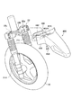
図4は、本実施形態においてフェンダーを構成するフロントフェンダー400の平面図である。図5は、フロントフェンダー400の左側面図である。
(2) Shape of Fender FIG. 4 is a plan view of a
図4及び図5に示すように、フロントフェンダー400は、幅広部410、幅狭部420、幅広部430及び取付部440を有する。
As shown in FIGS. 4 and 5, the
幅広部410は、フロントフェンダー400の前部に形成される。具体的には、幅広部410は、幅狭部420よりも前方に形成される。本実施形態において、幅広部410は、前方幅広部を構成する。幅広部410は、本体部分410aと、突出部分410bとによって構成される。幅広部410は、自動二輪車10の平面視において、後方に行くに従って幅が広がる形状を有する。
The
本体部分410aは、車幅方向におけるフロントフェンダー400の中心線CLを含む位置に形成される。突出部分410bは、本体部分410aから車幅方向外側に向けて突出している。突出部分410bは、本体部分410aよりも低い位置に形成される。具体的には、突出部分410bは、自動二輪車10の前後方向(図5に示すF−R方向)に垂直な断面内において、本体部分410aよりも低い位置に形成される。
The
幅広部410には、車幅方向において最も幅が広い最大幅部分411が形成される。具体的には、最大幅部分411は、自動二輪車10の後方に行くに従って幅が広がる突出部分410bの後部に形成される。
A
また、図3に示すように、本実施形態では、幅広部410の車幅方向における最大幅部分411の寸法(図中幅W2)のは、前輪20の車輪幅W1以上に設定される。
As shown in FIG. 3, in the present embodiment, the dimension (width W2 in the drawing) of the
さらに、最大幅部分411の寸法は、ヘッドライト281の車幅方向における最大幅部分の寸法(図中の幅W3)と略同一である。
Further, the dimension of the
幅狭部420は、車幅方向に広がった幅広部410よりも幅が狭い。幅狭部420の斜め後方には、アンダーカウル35(図4及び図5において不図示、図7参照)が配設される。
The
幅広部430は、自動二輪車10の平面視において、幅狭部420よりも車幅方向に広がっている。本実施形態において、幅広部430は、後方幅広部を構成する。幅広部430は、幅狭部420の後方であって、フロントフォーク21L,21Rの前方に形成される。幅広部430は、幅広部410の最大幅部分411よりもさらに車幅方向外側に広がっている。
The
また、幅狭部420及び幅広部430の前縁部430aは、アンダーカウル35の形状に沿っている。一方、幅広部430の後縁部430aは、円筒状のフロントフォーク21L,21Rの形状に合わせて円弧状に形成される。
Further, the
取付部440は、幅広部430に連なり、自動二輪車10の後方に向けて延びる。取付部440は、フロントフォーク21L,21Rを連結するアンダーブラケット22(図3及び図6参照)に取り付けられる。
The
このため、取付部440には、ボルト450が挿通されるボルト孔441L,441R及び442が形成される。
For this reason, bolt holes 441L, 441R and 442 through which the
(3)フェンダーの取付状態
次に、図6及び図7を参照して、フロントフェンダー400の取付状態について説明する。図6は、前輪20を含む自動二輪車10前部の右前方からの斜視図である。図7は、自動二輪車10前部の平面図である。
(3) Fender attachment state Next, with reference to FIG.6 and FIG.7, the attachment state of the
図6に示すように、フロントフェンダー400は、フロントフォーク21L,21Rを連結するアンダーブラケット22に取り付けられる。具体的には、取付部440は、フロントフォーク21Lとフロントフォーク21Rとの間に配設される。取付部440に形成されたるボルト孔441L,441R及び442には、ボルト450がそれぞれ挿通される。
As shown in FIG. 6, the
ボルト孔441L,441R及び442に挿通されたボルト450は、アンダーブラケット22に形成されたボルト受け部22a〜22cに螺入される。
アンダーブラケット22に取り付けられたフロントフェンダー400は、ハンドル23(図1〜図3参照)の操作に伴う前輪20の回動のみに対して前輪20とともに回動する。すなわち、フロントフェンダー400は、フロントフォーク21L,21Rによって上下動(ストローク)が可能に支持された前輪20とは独立している。このため、フロントフェンダー400は、前輪20とともには上下方向に移動せず、前輪20とフロントフェンダー400とのクリアランスは、走行状況に応じて随時変化する。
The
図7は、フロントフェンダー400と、車体カバー、具体的には、アンダーカウル35との位置関係を示す。図7に示すように、フロントフェンダー400は、ハンドル23(図1〜図3参照)が操作されると、前輪20とともに右方向(または左方向)に回動する。
FIG. 7 shows the positional relationship between the
前輪20が右方向(または左方向)に回動した場合におけるフロントフェンダー400とアンダーカウル35との干渉を回避するため、幅狭部420及び幅広部430(具体的には、前縁部430a)は、アンダーカウル35の形状に沿っている。幅狭部420及び幅広部430は、前輪20がハンドル23の操作に伴って回動すると、アンダーカウル35の外側面35aを沿って移動する。また、外側面35aは、幅狭部420及び幅広部430との干渉を回避しつつ、アンダーカウル35を前方に延在させるため、自動二輪車10の平面視において、後方に向けて凹む略円弧状に形成される。
In order to avoid interference between the
(4)作用・効果
自動二輪車10によれば、フロントフェンダー400には、車幅方向に広がった幅広部410が設けられる。幅広部410の後方には、幅広部410よりも幅が狭い幅狭部420が設けられる。また、幅狭部420の斜め後方には、ライダーの脚部の前方に配設されるレッグシールド30及びアンダーカウル35が配設される。
(4) Action / Effect According to the
このため、車輪が巻き上げた泥などがアンダーカウル35やフロントカバー200などに付着することを幅広部410によって効果的に防止できる。また、幅広部410の後方には幅狭部420が設けられるため、アンダーカウル35との干渉を回避しつつフロントフェンダー400の寸法を大型化できる。
For this reason, it is possible to effectively prevent the
本実施形態では、幅広部410の最大幅部分411の寸法(幅W2)は、前輪20の車輪幅W1以上である。また、幅広部410の突出部分410bは、本体部分410aよりも低い位置に形成される。さらに、幅広部410は、後方に行くに従って幅が広がっている。このため、前輪20が巻き上げた泥などの飛散をより効果的に防止できる。
In the present embodiment, the dimension (width W2) of the
本実施形態では、幅狭部420は、前輪20がハンドル23の操作に伴って回動すると、アンダーカウル35の外側面35aを沿って移動する。このため、アンダーカウル35との干渉を回避しつつ、フロントフェンダー400の寸法を大型化できるとともに、アンダーカウル35を前方に延在させることができる。
In the present embodiment, the
本実施形態では、幅広部430が幅狭部420の後方に形成される。また、幅広部430は、フロントフォーク21L,21Rの前方に形成される。このため、幅狭部420によってアンダーカウル35との干渉を回避しつつ、フロントフォーク21L,21Rへの泥などの付着を防止できる。
In the present embodiment, the
本実施形態では、幅広部410の最大幅部分411の寸法(幅W2)は、ヘッドライト281の車幅方向における最大幅部分の寸法(幅W3)と略同一である。また、ヘッドライト281の下端部281aは、フロントカバー200の下部200aに形成された切欠き部200bに配設される。このため、低い位置に配設されたヘッドライト281への泥などの付着を効果的に防止できる。
In the present embodiment, the dimension (width W2) of the
(5)その他の実施形態
上述したように、本発明の一実施形態を通じて本発明の内容を開示したが、この開示の一部をなす論述及び図面は、本発明を限定するものであると理解すべきではない。この開示から当業者には様々な代替実施の形態が明らかとなろう。
(5) Other Embodiments As described above, the content of the present invention has been disclosed through one embodiment of the present invention. However, it is understood that the description and drawings constituting a part of this disclosure limit the present invention. should not do. From this disclosure, various alternative embodiments will be apparent to those skilled in the art.
例えば、上述した実施形態では、幅広部410の最大幅部分411の寸法(幅W2)は、ヘッドライト281の車幅方向における最大幅部分の寸法(幅W3)と略同一であったが、幅広部410の最大幅部分411の寸法は、ヘッドライト281の寸法よりも大きくしてもよい。一方、上述した実施形態では、幅広部410の最大幅部分411の寸法(幅W2)は、前輪20の車輪幅W1以上であったが、必ずしも前輪20の車輪幅W1以上としなくてもよい。また、突出部分410bや幅広部430は、設けなくても構わない。
For example, in the above-described embodiment, the size (width W2) of the
上述した実施形態では、前輪20は、一対のフロントフォーク21L,21Rによって支持されていたが、前輪20は、一対のフォークに代えて、車体フレーム100に揺動可能に支持されるアームによって支持されても構わない。
In the embodiment described above, the
また、上述した実施形態では、前輪20の上方に配設されるフロントフェンダー400を例として説明したが、後輪90の上方にフロントフェンダー400と同様な形状を有するフェンダーを設けてもよい。
In the embodiment described above, the
このように、本発明は、ここでは記載していない様々な実施の形態などを含むことは勿論である。したがって、本発明の技術的範囲は、上述の説明から妥当な特許請求の範囲に係る発明特定事項によってのみ定められるものである。 As described above, the present invention naturally includes various embodiments that are not described herein. Therefore, the technical scope of the present invention is defined only by the invention specifying matters according to the scope of claims reasonable from the above description.
10…自動二輪車、20…前輪、21L,21R…フロントフォーク、22…アンダーブラケット、22a〜22c…ボルト受け部、23…ハンドル、30…レッグシールド、35…アンダーカウル、35a…外側面、40…フートボード、50…ユニットスイング式エンジン、80…シート、90…後輪、100…車体フレーム、110…ステアリングヘッドパイプ、200…フロントカバー、200a…下部、200b…切欠き部、281…ヘッドライト、281a…下端部、286…補助ライト、400…フロントフェンダー、410…幅広部、410a…本体部分、410b…突出部分、411…最大幅部分、420…幅狭部、430…幅広部、430a…前縁部、430a…後縁部、440…取付部、441L,441R,442…ボルト孔、450…ボルト、640…マッドガード、CL…中心線、S…空間、W1…車輪幅、W2,W3…幅
DESCRIPTION OF
Claims (9)
前記車輪の上方に配設され、ハンドルの操作に伴って前記車輪とともに回動するフェンダーと、
前記車輪の後方において、ライダーの脚部の前方に配設される車体カバーと
を備えるスクータ型車両であって、
前記フェンダーは、
前記スクータ型車両の平面視において、車幅方向に広がった前方幅広部と、
前記スクータ型車両の平面視において、前記前方幅広部よりも幅が狭い幅狭部と
を有し、
前記前方幅広部は、前記幅狭部よりも前方に形成され、
前記幅狭部の斜め後方には、前記車体カバーが配設されるスクータ型車両。 Wheels,
A fender disposed above the wheel and rotating with the wheel in accordance with the operation of the handle;
A scooter type vehicle including a vehicle body cover disposed behind the wheel and in front of the rider's legs,
The fender is
In a plan view of the scooter type vehicle, a wide front part widened in the vehicle width direction;
In a plan view of the scooter type vehicle, it has a narrow part narrower than the front wide part,
The wide front part is formed in front of the narrow part,
A scooter type vehicle in which the vehicle body cover is disposed obliquely behind the narrow portion.
前記フェンダーは、前記スクータ型車両の平面視において、前記幅狭部よりも車幅方向に広がった後方幅広部を有し、
前記後方幅広部は、前記幅狭部の後方であって、前記フォーク部の前方に形成される請求項1に記載のスクータ型車両。 A pair of forks for rotatably supporting the wheels;
The fender has a wide rear portion that is wider in the vehicle width direction than the narrow portion in a plan view of the scooter type vehicle,
The scooter type vehicle according to claim 1, wherein the wide rear part is formed behind the narrow part and in front of the fork part.
車幅方向における前記フェンダーの中心線を含む位置に形成される本体部分と、
前記本体部分から車幅方向外側に向けて突出した突出部分と
を有し、
前記突出部分は、前記スクータ型車両の前後方向に垂直な断面内において、前記本体部分よりも低い位置に形成される請求項1に記載のスクータ型車両。 The wide front part is
A body portion formed at a position including the center line of the fender in the vehicle width direction;
A projecting portion projecting outward from the main body portion in the vehicle width direction,
The scooter type vehicle according to claim 1, wherein the protruding portion is formed at a position lower than the main body portion in a cross section perpendicular to the front-rear direction of the scooter type vehicle.
前記フェンダーは、前記スクータ型車両の略上下方向に沿った前記車輪の移動とは独立し、前記ハンドルの操作に伴う前記車輪の回動のみに対して前記車輪とともに回動する請求項1に記載のスクータ型車両。 A wheel support portion for supporting the wheel movably along the substantially vertical direction of the scooter type vehicle;
The said fender is independent of the movement of the said wheel along the substantially up-down direction of the said scooter type vehicle, and rotates with the said wheel only with respect to rotation of the said wheel accompanying operation of the said handle | steering-wheel. Scooter type vehicle.
前記前方幅広部の車幅方向における最大幅部分の寸法は、前記灯火器の車幅方向における最大幅部分の寸法と略同一、または前記灯火器の車幅方向における最大幅部分の寸法よりも大きい請求項1に記載のスクータ型車両。 A lighting device disposed above the fender,
The dimension of the maximum width part in the vehicle width direction of the front wide part is substantially the same as the dimension of the maximum width part in the vehicle width direction of the lamp or larger than the dimension of the maximum width part of the lamp in the vehicle width direction. The scooter type vehicle according to claim 1.
前記前部カバー部の下部には、切欠き部分が形成され、
前記灯火器の少なくとも一部は、前記切欠き部分に配設される請求項8に記載のスクータ型車両。 A front cover portion disposed around the lighting device;
A notch portion is formed in the lower portion of the front cover portion,
The scooter-type vehicle according to claim 8, wherein at least a part of the lighting device is disposed in the notch portion.
Priority Applications (1)
| Application Number | Priority Date | Filing Date | Title |
|---|---|---|---|
| JP2007241647A JP2009073224A (en) | 2007-09-18 | 2007-09-18 | Scooter type vehicle |
Applications Claiming Priority (1)
| Application Number | Priority Date | Filing Date | Title |
|---|---|---|---|
| JP2007241647A JP2009073224A (en) | 2007-09-18 | 2007-09-18 | Scooter type vehicle |
Publications (1)
| Publication Number | Publication Date |
|---|---|
| JP2009073224A true JP2009073224A (en) | 2009-04-09 |
Family
ID=40608662
Family Applications (1)
| Application Number | Title | Priority Date | Filing Date |
|---|---|---|---|
| JP2007241647A Pending JP2009073224A (en) | 2007-09-18 | 2007-09-18 | Scooter type vehicle |
Country Status (1)
| Country | Link |
|---|---|
| JP (1) | JP2009073224A (en) |
Cited By (1)
| Publication number | Priority date | Publication date | Assignee | Title |
|---|---|---|---|---|
| JP2017171275A (en) * | 2016-03-18 | 2017-09-28 | ヤマハ発動機株式会社 | Lean vehicle |
-
2007
- 2007-09-18 JP JP2007241647A patent/JP2009073224A/en active Pending
Cited By (1)
| Publication number | Priority date | Publication date | Assignee | Title |
|---|---|---|---|---|
| JP2017171275A (en) * | 2016-03-18 | 2017-09-28 | ヤマハ発動機株式会社 | Lean vehicle |
Similar Documents
| Publication | Publication Date | Title |
|---|---|---|
| JP5171149B2 (en) | Arrangement structure of fall sensor in motorcycle | |
| JP2010120629A (en) | Scooter type vehicle | |
| TWI738397B (en) | Tilting vehicle | |
| JP6448157B2 (en) | Motorcycle headlight guard structure | |
| JP6356627B2 (en) | A saddle-ride type vehicle equipped with a blinker | |
| JP2015085743A (en) | Reinforcement structure of front fender | |
| JP2009073224A (en) | Scooter type vehicle | |
| JP2010058762A (en) | Saddle-riding type vehicle | |
| EP2610150B1 (en) | Saddle-ride type vehicle | |
| JP5977670B2 (en) | Saddle riding | |
| ITTO950562A1 (en) | FRONT STRUCTURE OF THE BODY OF A VEHICLE OF THE SCOOTER TYPE | |
| JP2009154843A (en) | Front fender and motorcycle | |
| JPH11263264A (en) | Horn cover | |
| JP2009073225A (en) | Scooter type vehicle | |
| JP7177757B2 (en) | Straddle-type vehicle step structure | |
| TWI465361B (en) | Straddle type vehicle | |
| WO2022163249A1 (en) | Saddled vehicle | |
| TWI664106B (en) | Straddled vehicle | |
| JP2000313384A (en) | Astriding type four-wheeled vehicle | |
| JP2006281878A (en) | Motorcycle | |
| WO2013133317A1 (en) | Structure for front part of saddle-type vehicle | |
| JP2022138473A (en) | Saddle riding vehicle | |
| JP2023051181A (en) | Saddle-riding type vehicle | |
| JP2004098830A (en) | Front fender structure for motorcycle | |
| JPH11263266A (en) | Step bracket for motorcycle |