JP2009071663A - Movement mechanism and imaging apparatus - Google Patents
Movement mechanism and imaging apparatus Download PDFInfo
- Publication number
- JP2009071663A JP2009071663A JP2007239055A JP2007239055A JP2009071663A JP 2009071663 A JP2009071663 A JP 2009071663A JP 2007239055 A JP2007239055 A JP 2007239055A JP 2007239055 A JP2007239055 A JP 2007239055A JP 2009071663 A JP2009071663 A JP 2009071663A
- Authority
- JP
- Japan
- Prior art keywords
- moving
- beams
- moved
- fixed
- unit
- Prior art date
- Legal status (The legal status is an assumption and is not a legal conclusion. Google has not performed a legal analysis and makes no representation as to the accuracy of the status listed.)
- Pending
Links
- 230000007246 mechanism Effects 0.000 title claims abstract description 78
- 238000003384 imaging method Methods 0.000 title claims abstract description 57
- 238000000034 method Methods 0.000 claims description 37
- 230000003287 optical effect Effects 0.000 claims description 26
- 238000007789 sealing Methods 0.000 claims description 18
- 238000004519 manufacturing process Methods 0.000 claims description 16
- 239000004065 semiconductor Substances 0.000 claims description 13
- 239000000463 material Substances 0.000 claims description 11
- 238000007639 printing Methods 0.000 claims description 3
- 238000010586 diagram Methods 0.000 description 13
- XUIMIQQOPSSXEZ-UHFFFAOYSA-N Silicon Chemical compound [Si] XUIMIQQOPSSXEZ-UHFFFAOYSA-N 0.000 description 9
- 229910052710 silicon Inorganic materials 0.000 description 9
- 239000010703 silicon Substances 0.000 description 9
- 238000005260 corrosion Methods 0.000 description 8
- 230000007797 corrosion Effects 0.000 description 8
- 239000000428 dust Substances 0.000 description 8
- 238000005516 engineering process Methods 0.000 description 7
- 239000006059 cover glass Substances 0.000 description 6
- 230000008602 contraction Effects 0.000 description 5
- 230000001133 acceleration Effects 0.000 description 4
- 230000002093 peripheral effect Effects 0.000 description 4
- 239000000758 substrate Substances 0.000 description 4
- 239000000853 adhesive Substances 0.000 description 2
- 230000001070 adhesive effect Effects 0.000 description 2
- 230000015572 biosynthetic process Effects 0.000 description 2
- 230000005684 electric field Effects 0.000 description 2
- 241000270295 Serpentes Species 0.000 description 1
- 229910004298 SiO 2 Inorganic materials 0.000 description 1
- VYPSYNLAJGMNEJ-UHFFFAOYSA-N Silicium dioxide Chemical compound O=[Si]=O VYPSYNLAJGMNEJ-UHFFFAOYSA-N 0.000 description 1
- 229920001940 conductive polymer Polymers 0.000 description 1
- 238000001514 detection method Methods 0.000 description 1
- 238000005530 etching Methods 0.000 description 1
- 230000006872 improvement Effects 0.000 description 1
- 239000012535 impurity Substances 0.000 description 1
- 150000002500 ions Chemical class 0.000 description 1
- 239000004973 liquid crystal related substance Substances 0.000 description 1
- 239000002184 metal Substances 0.000 description 1
- 210000003205 muscle Anatomy 0.000 description 1
- 229920000642 polymer Polymers 0.000 description 1
- 230000008569 process Effects 0.000 description 1
- 229910052814 silicon oxide Inorganic materials 0.000 description 1
- 238000007740 vapor deposition Methods 0.000 description 1
Images

Landscapes
- Transforming Light Signals Into Electric Signals (AREA)
- Studio Devices (AREA)
Abstract
Description
本発明は、移動機構および撮像装置に関し、特に、固定部と梁で接続された移動部を梁のバネ性によって駆動部の駆動方向と平行に移動させる移動機構および該移動機構を用いた撮像装置に関する。 The present invention relates to a moving mechanism and an imaging apparatus, and more particularly, to a moving mechanism that moves a moving part connected by a fixed part and a beam in parallel with the driving direction of the driving part by the spring property of the beam, and an imaging apparatus using the moving mechanism. About.
近年、携帯電話等に、高倍率ズームレンズとオートフォーカス機能や手ブレ補正機能を備えた超小型のマイクロカメラユニット(以下、MCUと言う)が搭載されてきている。MCU等の超小型撮像装置においては、オートフォーカス機能や手ブレ補正機能を実現するために使えるスペースが限られており、限られたスペースの範囲でいかに高性能化するかがポイントとなる。この際に、撮像光学系に比べて小型軽量な撮像素子を移動させる方法がある。 In recent years, ultra-small micro camera units (hereinafter referred to as MCUs) equipped with a high-power zoom lens, an autofocus function, and a camera shake correction function have been mounted on mobile phones and the like. In an ultra-small imaging device such as an MCU, a space that can be used for realizing an autofocus function and a camera shake correction function is limited, and the point is how to improve the performance within the limited space. At this time, there is a method of moving an image sensor that is smaller and lighter than the imaging optical system.
撮像素子を移動させる方法での高性能化のためには、例えばオートフォーカス機能では、撮像素子をMCUの撮像光学系の光軸に平行に移動させる必要があり、例えば手ブレ補正機能では、撮像素子をMCUの撮像光学系の光軸に垂直な面内で平行に移動させる必要がある。 In order to achieve high performance in the method of moving the image sensor, for example, in the auto focus function, it is necessary to move the image sensor in parallel to the optical axis of the imaging optical system of the MCU. It is necessary to move the element in parallel in a plane perpendicular to the optical axis of the imaging optical system of the MCU.
そこで、例えばオートフォーカス機能の達成のために、小型の静電駆動アクチュエータを複数用意し、各アクチュエータのバネ力によって、撮像素子を光学系の光軸に平行に移動させる方法が提案されている(例えば、特許文献1参照)。
しかし、特許文献1の方法では、撮像素子の裏面の非常に小さい面積下に多くの小型アクチュエータを配置する必要がある。もし配置するアクチュエータの個数が少ないと、アクチュエータの駆動力のバラツキ等によって撮像素子が傾いたり蛇行したりしてオートフォーカス性能が劣化する。 However, in the method of Patent Document 1, it is necessary to arrange many small actuators under a very small area on the back surface of the image sensor. If the number of actuators to be arranged is small, the image pickup device tilts or snakes due to variations in the driving force of the actuators and the autofocus performance deteriorates.
また、多くのアクチュエータを配置するためにはアクチュエータをより微細に製造する必要があり、製造上の課題が大きい。さらに、アクチュエータを小型化すると発生力も弱くなり、駆動距離も小さくなって撮像素子を移動させることができなくなる。 Moreover, in order to arrange many actuators, it is necessary to manufacture the actuators more finely, and the manufacturing problems are great. Further, when the actuator is downsized, the generated force is weakened, the driving distance is reduced, and the image pickup device cannot be moved.
本発明は、上記事情に鑑みてなされたもので、複数の駆動部を用いることなく、駆動部自体の駆動に依存することもなく、移動部を駆動部の駆動方向と平行に移動させることのできる移動機構および該移動機構を用いた撮像装置を提供することを目的とする。 The present invention has been made in view of the above circumstances, and without using a plurality of driving units, without depending on driving of the driving unit itself, the moving unit can be moved in parallel with the driving direction of the driving unit. It is an object of the present invention to provide a moving mechanism that can be used and an imaging apparatus using the moving mechanism.
本発明の目的は、下記構成により達成することができる。 The object of the present invention can be achieved by the following constitution.
1.少なくとも底面と側面とからなる凹部を有する固定部と、
被移動部を搭載するための平板状の移動部と、
前記移動部の前記被移動部を搭載した面の裏面と前記凹部の底面との間に設けられ、前記移動部を前記凹部の底面に垂直な方向に移動させる駆動部と、
一端が前記移動部に固定され、他端が前記凹部の側面に固定され、前記移動部が移動される方向にバネ性が付与されている複数の梁を備えたことを特徴とする移動機構。
1. A fixed portion having a recess composed of at least a bottom surface and a side surface;
A plate-shaped moving part for mounting the moved part;
A drive unit that is provided between the back surface of the surface of the moving unit on which the moving unit is mounted and the bottom surface of the recess, and moves the moving unit in a direction perpendicular to the bottom surface of the recess;
A moving mechanism comprising: a plurality of beams having one end fixed to the moving portion, the other end fixed to a side surface of the recess, and spring properties in a direction in which the moving portion is moved.
2.複数の前記梁は、一端が前記移動部の同一端面の厚み方向に異なる位置に固定された片持ち支持梁であり、
複数の前記梁と前記移動部の端面と前記凹部の複数の前記梁が固定される側面とが平行四辺形を形成することを特徴とする1に記載の移動機構。
2. The plurality of beams are cantilevered support beams whose one ends are fixed at different positions in the thickness direction of the same end surface of the moving unit,
2. The moving mechanism according to 1, wherein the plurality of beams, end surfaces of the moving unit, and side surfaces to which the plurality of beams of the concave portion are fixed form a parallelogram.
3.複数の前記梁は、一端が前記移動部の少なくとも対向する1対の端面に固定され、他端が前記凹部の対向する側面に固定されていることを特徴とする1に記載の移動機構。 3. 2. The moving mechanism according to 1, wherein one end of each of the plurality of beams is fixed to at least one pair of opposing end surfaces of the moving unit, and the other end is fixed to the opposing side surfaces of the concave portion.
4.前記被移動部は、半導体製造プロセスで形成される電子回路部であり、
前記移動部と複数の前記梁とは前記被移動部と同一の主材料で形成され、
前記被移動部は、少なくともその一部が前記移動部に直接接合技術により接合されていることを特徴とする1乃至3の何れか1項に記載の移動機構。
4). The moved part is an electronic circuit part formed in a semiconductor manufacturing process,
The moving part and the plurality of beams are formed of the same main material as the moved part,
The moving mechanism according to any one of claims 1 to 3, wherein at least a part of the moved part is joined to the moving part by a direct joining technique.
5.前記被移動部、前記移動部および複数の前記梁は前記凹部内に収納されており、
前記凹部を覆う封止部を備え、
前記凹部は、前記固定部と前記封止部とにより密封されていることを特徴とする1乃至4の何れか1項に記載の移動機構。
5). The moved portion, the moving portion, and the plurality of beams are housed in the recess,
A sealing portion covering the recess,
The moving mechanism according to any one of claims 1 to 4, wherein the concave portion is sealed by the fixing portion and the sealing portion.
6.前記移動部と複数の前記梁の少なくとも1つとに、前記被移動部と外部とを接続する配線を形成したことを特徴とする1乃至5の何れか1項に記載の移動機構。 6). The moving mechanism according to any one of claims 1 to 5, wherein a wiring for connecting the moved portion and the outside is formed on at least one of the moving portion and the plurality of beams.
7.被移動部を搭載するための平板状の第1の移動部と、
前記第1の移動部と同一面内で、前記第1の移動部の少なくとも3方を囲むように設けられた第1の固定部と、
前記第1の移動部と前記第1の固定部との間に配置され、前記第1の移動部を前記第1の固定部に対して同一面内で移動させる複数の第1の駆動部と
一端が前記第1の移動部の同一端面に固定され、他端が前記第1の固定部に固定され、前記第1の移動部が移動される方向にバネ性が付与された複数の第1の梁と、
少なくとも底面と側面とからなる凹部を有する第2の固定部と、
前記第1の固定部と前記第2の固定部との間に配置され、前記第1の固定部を前記第2の固定部に対して同一面内で前記第1の移動部の移動方向と垂直な方向に移動させる複数の第2の駆動部と、
一端が前記第1の固定部の同一端面に固定され、他端が前記第2の固定部の側面に固定され、前記第1の固定部が移動される方向にバネ性が付与された複数の第2の梁とを備えたことを特徴とする移動機構。
7). A flat plate-like first moving part for mounting the moved part;
A first fixed portion provided to surround at least three sides of the first moving portion in the same plane as the first moving portion;
A plurality of first drive units disposed between the first moving unit and the first fixed unit, the first driving unit moving the first moving unit with respect to the first fixed unit in the same plane; One end is fixed to the same end surface of the first moving part, the other end is fixed to the first fixing part, and a plurality of first elements are provided with a spring property in a direction in which the first moving part is moved. And
A second fixing portion having a recess composed of at least a bottom surface and a side surface;
The first fixing portion is disposed between the first fixing portion and the second fixing portion, and the first fixing portion is moved in the same plane with respect to the second fixing portion, and the moving direction of the first moving portion is A plurality of second drive units that move in a vertical direction;
One end is fixed to the same end surface of the first fixing portion, the other end is fixed to a side surface of the second fixing portion, and a plurality of spring properties are provided in a direction in which the first fixing portion is moved. A moving mechanism comprising a second beam.
8.前記被移動部は、半導体製造プロセスで形成される電子回路部であり、
前記第1の移動部、前記第1の固定部、複数の前記第1の梁、および複数の前記第2の梁は前記被移動部と同一の主材料で形成され、
前記被移動部は、少なくともその一部が前記第1の移動部に直接接合技術により接合されていることを特徴とする7に記載の移動機構。
8). The moved part is an electronic circuit part formed in a semiconductor manufacturing process,
The first moving part, the first fixed part, the plurality of first beams, and the plurality of second beams are formed of the same main material as the moved part,
8. The moving mechanism according to 7, wherein at least a part of the moved part is joined to the first moving part by a direct joining technique.
9.前記被移動部、前記第1の移動部、前記第1の固定部、複数の前記第1の駆動部、複数の前記第1の梁、複数の前記第2の駆動部および複数の前記第2の梁は前記凹部内に収納されており、
前記凹部を覆う封止部を備え、
前記凹部は、前記固定部と前記封止部とにより密封されていることを特徴とする7または8に記載の移動機構。
9. The moved portion, the first moving portion, the first fixed portion, the plurality of first drive portions, the plurality of first beams, the plurality of second drive portions, and the plurality of second portions. Is housed in the recess,
A sealing portion covering the recess,
The moving mechanism according to claim 7 or 8, wherein the concave portion is sealed by the fixing portion and the sealing portion.
10.前記第1の移動部、複数の前記第1の梁の少なくとも1つ、前記第1の固定部および複数の前記第2の梁の少なくとも1つに、前記被移動部と外部とを接続する配線を形成したことを特徴とする7乃至9の何れか1項に記載の移動機構。 10. Wiring for connecting the moved part and the outside to at least one of the first moving part, at least one of the plurality of first beams, the first fixed part and the plurality of second beams. 10. The moving mechanism according to any one of 7 to 9, wherein
11.前記配線は、印刷により形成されることを特徴とする6または10に記載の移動機構。
11. The moving mechanism according to
12.撮像光学系と、
1乃至11の何れか1項に記載の移動機構とを備え、
前記被移動部は撮像センサであることを特徴とする撮像装置。
12 An imaging optical system;
The moving mechanism according to any one of 1 to 11,
An image pickup apparatus, wherein the moved part is an image sensor.
本発明によれば、バネ性を備えた梁によって移動部と固定部とを接続し、駆動部によって移動部を移動させることで、複数の駆動部を用いることなく、駆動部自体の駆動に依存することもなく、移動部を駆動部の駆動方向と平行に移動させることのできる移動機構および該移動機構を用いた撮像装置を提供することができる。 According to the present invention, the moving unit and the fixed unit are connected by a beam having a spring property, and the moving unit is moved by the driving unit, so that it depends on driving of the driving unit itself without using a plurality of driving units. Accordingly, it is possible to provide a moving mechanism capable of moving the moving unit in parallel with the driving direction of the driving unit and an imaging apparatus using the moving mechanism.
以下、本発明を図示の実施の形態に基づいて説明するが、本発明は該実施の形態に限られない。なお、図中、同一あるいは同等の部分には同一の番号を付与し、重複する説明は省略する。 Hereinafter, the present invention will be described based on the illustrated embodiment, but the present invention is not limited to the embodiment. In the drawings, the same or equivalent parts are denoted by the same reference numerals, and redundant description is omitted.
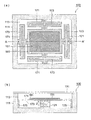
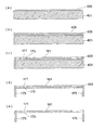
まず、本発明の第1の実施の形態について、図1乃至図3を用いて説明する、図1は、本発明における移動機構の第1の実施の形態を示す模式図で、図1(a)は平面図、図1(b)は図1(a)のA−A’断面図である。 First, a first embodiment of the present invention will be described with reference to FIGS. 1 to 3. FIG. 1 is a schematic diagram showing a first embodiment of a moving mechanism in the present invention, and FIG. ) Is a plan view, and FIG. 1B is a cross-sectional view taken along line AA ′ of FIG.
図1(a)および(b)において、移動機構100は、固定部111、被移動部151、移動部161、4つの梁171、4つの梁支持部175および駆動部121等で構成される。
1A and 1B, the moving
移動部161は剛性を持つ矩形の平板であり、矩形の4辺の各中央部で4つの梁171と接続され、一体に形成されている。移動部161と4つの梁171とは、固定部111の凹部113内に収納され、移動部161は4つの梁171を介して固定部111の凹部113の内壁に接している。
The moving
梁171は、移動部161および固定部111と接続される部分の幅が狭く、中央部が広い形状である。梁171の中央部にはスリット173(図1(a)では十字形のスリット)が設けられ、これによって駆動部121の駆動方向(図1(b)のZ方向)にバネ性が付与されている。
The
被移動部151は、例えば撮像素子、加速度センサ、位置センサ、温度センサ等のセンサ類や、それらと周辺回路とを集積した集積回路等のような半導体製造プロセスで製造される電子回路であり、移動部161の一方の平面上に搭載され、少なくともその一部が移動部161に固定されている。固定方法については後述する。
The moved
駆動部121は、移動部161の被移動部151搭載面の裏面と固定部111との間に配置され、移動部161を図1(b)のZ方向に移動させる。駆動部121としては、例えば積層型圧電素子、静電アクチュエータ等が考えられるが、それに限るものではなく、その他にも多くのアクチュエータが使用可能である。詳細は後述する。
The driving
梁171の固定部111の内壁に接する部分には、移動部161と4つの梁171とを固定部111の凹部の底面から駆動部121の高さ分だけ持ち上げるための梁支持部175が設けられている。梁支持部175は、移動部161および4つの梁171と一体に形成され、梁171の固定部111の内壁に接する部分で図の−Z方向に直角に形成されている。移動部161、4つの梁171および梁支持部175の形成方法については後述する。
A
被移動部151、移動部161、4つの梁171、4つの梁支持部175および駆動部121は全て固定部111の凹部113内に収納されており、カバーガラス等の封止部材131によって封止されている。これによって、被移動部151の表面へのゴミの付着、梁171への異物の噛み込みや、湿度による各部の腐食等を防止することができる。
The moved
図2は、図1に示した移動機構100の動作状態を示す模式図である。
FIG. 2 is a schematic diagram illustrating an operation state of the moving
図2において、駆動部121は、図示しない外部駆動回路からの信号により、図のZ方向に伸縮する。移動部161は剛性を持つ平板であるため、駆動部121の伸縮に同期して図のZ方向に移動する。この際、移動部161の4辺がZ方向にバネ性を持つ4つの梁171によって固定部111に接続されているので、4つの梁171のバネ性の釣り合いにより、移動部161は、その面上に被移動部151を搭載した状態で、傾くことなしにZ方向に平行に移動される。
In FIG. 2, the
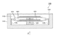
図3は、図1に示した梁支持部175の他の実施形態を示す模式図である。
FIG. 3 is a schematic view showing another embodiment of the
図3においては、図1に示したような梁支持部175は設けられておらず、その代わりに固定部111の内壁部に、梁171を支持するための突起部115が設けられている。一体に形成された移動部161と梁171とは、図の+Z方向から固定部111の凹部113内に挿入され、移動部161の裏面が駆動部121の上面に接し、梁171の固定部111の内壁に接する部分が突起部115の上面に接する。移動部161の裏面と駆動部121の上面、および梁171の固定部111の内壁に接する部分と突起部115の上面とはそれぞれ例えば接着等により固定される。図3に示した例において、移動機構100の動作は図2に示したと同じである。
In FIG. 3, the
上述したように、本発明の第1の実施の形態によれば、駆動部121の伸縮によって移動部161をZ方向に移動させる際に、移動部161の4辺を固定部111に接続している4つの梁171のバネ性の釣り合いにより、移動部161を傾くことなしにZ方向に平行に移動させることができ、移動部161の面上に搭載された被移動部151も、傾くことなしにZ方向に平行に移動させることができる。
As described above, according to the first embodiment of the present invention, when the moving
さらに、被移動部151、移動部161、4つの梁171および駆動部121等が全て固定部111の凹部113内に収納されており、カバーガラス等の封止部材131によって封止されているので、被移動部151の表面へのゴミの付着、梁171への異物の噛み込みや、湿度による各部の腐食等を防止することができる。
Further, the moved
次に、本発明の第2の実施の形態について、図4および図5を用いて説明する。図4は、本発明における移動機構の第2の実施の形態を示す模式図で、図4(a)は平面図、図4(b)は図4(a)のB−B’断面図、図4(c)は図4(a)のC−C’断面図である。 Next, a second embodiment of the present invention will be described with reference to FIGS. FIG. 4 is a schematic view showing a second embodiment of the moving mechanism in the present invention, FIG. 4 (a) is a plan view, FIG. FIG. 4C is a cross-sectional view taken along the line CC ′ of FIG.
図4(a)(b)および(c)において、移動機構100は、固定部111、被移動部151、移動部161、2本の梁181、2本の梁183、4カ所の突起部115および駆動部121等で構成される。
4A, 4 </ b> B, and 4 </ b> C, the moving
移動部161は剛性を持つ矩形の平板であり、矩形の1辺の端面の4カ所で2本の梁181および2本の梁183と接続され、一体に形成されている。移動部161と2本の梁181および2本の梁183とは、固定部111の凹部113内に収納され、移動部161は2本の梁181および2本の梁183を介して固定部111の凹部113の4カ所の突起部115に固定されている。
The moving
2本の梁181および2本の梁183は、所謂片持ち支持梁であり、4カ所の突起部115に固定された部分で支持されている。2本の梁181および2本の梁183の他端は、移動部161の矩形の1辺の端面の4カ所で移動部161と一体的に形成されている。
The two
図4(b)に示すように、2本の梁181および2本の梁183の位置は、移動部161の端面の厚み方向にそれぞれずらせて配置されている。これによって2本の梁181と2本の梁183とは所謂平行板バネを構成し、駆動部121の駆動方向(図4(c)のZ方向)にバネ性を持つ。ここで、例えば2本の梁181と2本の梁183との合計4つの梁を同一の形状とすることで、4つの梁の持つバネ性を同一とすることができる。
As shown in FIG. 4B, the positions of the two
被移動部151は、第1の実施の形態と同様に、例えば撮像素子、加速度センサ、位置センサ、温度センサ等のセンサ類や、それらと周辺回路とを集積した集積回路等のような半導体製造プロセスで製造される電子回路であり、移動部161の一方の平面上に搭載され、少なくともその一部が移動部161に固定されている。固定方法については後述する。
As in the first embodiment, the moved
駆動部121も、第1の実施の形態と同様に、移動部161の被移動部151搭載面の裏面と固定部111との間に配置され、移動部161を図4(c)のZ方向に移動させる。駆動部121としては、第1の実施の形態と同様に、例えば積層型圧電素子、静電アクチュエータ等が考えられるが、それに限るものではなく、その他にも多くのアクチュエータが使用可能である。詳細は後述する。
Similarly to the first embodiment, the
固定部111の突起部115は、図3に示したと同様の構成で、2本の梁181および2本の梁183の固定部111の内壁に接する部分を支持し、接着との方法により固定している。もちろん、図1に示した梁支持部175と同様の構成をとってもよい。
The protruding
被移動部151、移動部161、2本の梁181および2本の梁183、4つの突起部115および駆動部121は全て固定部111の凹部113内に収納されており、カバーガラス等の封止部材131によって封止されている。これによって、被移動部151の表面へのゴミの付着、2本の梁181および2本の梁183への異物の噛み込みや、湿度による各部の腐食等を防止することができる。
The moving
図5は、図4に示した移動機構100の動作状態を示す模式図である。
FIG. 5 is a schematic diagram illustrating an operation state of the moving
図5において、駆動部121は、図示しない外部駆動回路からの信号により、図のZ方向に伸縮する。移動部161は剛性を持つ平板であるため、駆動部121の伸縮に同期して図のZ方向に移動する。この際、図4で述べたように、2本の梁181と2本の梁183との4つの梁が持つバネ性は同一であるので、4つの梁バネ性の釣り合いにより、4つの梁と、4つの梁が固定されている移動部161の端面、および4つの梁が固定されている固定部111の内壁113が形作る平行四辺形が維持されるように移動部161が移動される。よって、移動部161は、その面上に被移動部151を搭載した状態で、傾くことなしにZ方向に平行に移動される。
In FIG. 5, the
上述したように、本発明の第2の実施の形態によれば、駆動部121の伸縮によって移動部161をZ方向に移動させる際に、移動部161の1辺を固定部111に接続している片持ち支持梁である2本の梁181および2本の梁183のバネ性の釣り合いにより、移動部161を傾くことなしにZ方向に平行に移動させることができ、移動部161の面上に搭載された被移動部151も、傾くことなしにZ方向に平行に移動させることができる。
As described above, according to the second embodiment of the present invention, when the moving
さらに、被移動部151、移動部161、2本の梁181、2本の梁183および駆動部121等が全て固定部111の凹部113内に収納されており、カバーガラス等の封止部材131によって封止されているので、被移動部151の表面へのゴミの付着、梁181および183への異物の噛み込みや、湿度による各部の腐食等を防止することができる。
Further, the moved
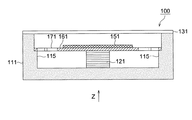
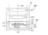
次に、上述した第1または第2の実施の形態の移動機構100を備えた撮像装置の1例を、図6を用いて説明する。図6は、上述した第2の実施の形態の移動機構100を備えた撮像装置10の1例を示す断面図である。
Next, an example of an imaging apparatus including the moving
図6において、撮像素子である被移動部151、移動部161、2本の梁181および2本の梁183および駆動部121は、撮像素子パッケージである固定部111の凹部113内に収納されている。固定部111の開口部は、赤外光(IR)カットフィルタである封止部材131によって封止されており、上述したMCUである撮像装置10のオートフォーカスユニットである移動機構100を構成している。
In FIG. 6, the moving
移動機構100の上には、鏡胴311内に撮像レンズ301と303とを固定して収納した撮像装置10の撮像光学系300が、例えば撮像光学系300の光軸305が被移動部151の画素部の中心に一致するように配置されている。固定部111と鏡胴311とは、例えば接着等により接続され、MCUである撮像装置10を構成している。
On the moving
撮像装置10のオートフォーカス動作時には、例えば撮像素子である被移動部151の画像信号に基づいて、図示しないオートフォーカス回路によって、被移動部151の撮像面上のピント状態の検出と被移動部151の移動方向の決定が行われる。オートフォーカス回路によって決定された移動方向に基づいて、図示しない外部駆動回路からの信号により、駆動部121が図のZ方向に伸縮され、図5に述べた原理によって被移動部151がZ方向に平行移動される。これによって、撮像光学系300と撮像素子である被移動部151との相対位置関係が変更される。以上の一連の動作が繰り返されて、撮像装置10のオートフォーカス動作が行われる。
During the autofocus operation of the
なお、図6では、第2の実施の形態の移動機構100を備えた撮像装置10の例を示したが、第1の実施の形態の移動機構100を用いても同じである。
FIG. 6 shows an example of the
上述したように、第1または第2の実施の形態の移動機構100を備えた撮像装置10によれば、第1または第2の実施の形態の移動機構100によって、撮像素子である被移動部151を光軸305に対して傾くことなく平行に移動させることができるので、画像の片ボケ等のない高画質な撮像装置10を提供することができる。
As described above, according to the
さらに、移動機構100が固定部111と封止部材131とで封止されているので、被移動部151の表面へのゴミの付着、梁171、あるいは梁181および183への異物の噛み込みや、湿度による各部の腐食等を防止することができ、信頼性の高い撮像装置10を提供することができる。
Further, since the moving
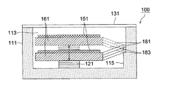
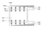
続いて、撮像素子である被移動部151の電源や画像信号等の配線を外部に取り出す方法の1例を、図7を用いて説明する。図7は、被移動部151の配線を外部に取り出す方法の1例を示す模式図である。図7では図4に示した移動機構100の第2の実施の形態における被移動部151、移動部161および梁181と183のみを図示してある。
Next, an example of a method for taking out the power supply of the moved
図7において、撮像素子である被移動部151上には、半導体製造プロセスによって形成される電源や画像信号等の配線のためのボンディングパッド151aが、例えば図7の例では8個備えられている。移動部161上の被移動部151のボンディングパッド151aに対向する位置にも、ボンディングパッド161aが備えられており、ボンディングパッド161aから梁181の端部まで配線161bが引かれている。対向するボンディングパッド151aと161aとの間は、ボンディングワイヤ155によって結線されている。
In FIG. 7, for example, eight bonding pads 151a for wiring such as a power source and an image signal formed by a semiconductor manufacturing process are provided on a moved
2本の梁181の端部の配線161bは、例えば導電性接着剤等により撮像素子パッケージである固定部111上の配線に結線され、これによって、撮像素子である被移動部151と撮像素子パッケージである固定部111の外部にある回路とが接続されて、信号の授受が行われる。
The
移動部161および梁181上のボンディングパッド161aおよび配線161bは、例えば半導体製造プロセスによって形成されてもよいし、例えばインクジェット方式等の印刷方法によって形成されてもよい。
The
上述したように移動部161および梁181上にボンディングパッド161aおよび配線161bを設けることにより、移動する被移動部151と固定部111の間にボンディングワイヤを結線する必要がなくなり、被移動部151の移動にともなってボンディングワイヤが揺り動かされて断線するという危険を防止することができ、移動機構100の信頼性の向上に寄与することができる。なお、上述した配線の形成方法は、図8で後述する本発明の第3の実施の形態においても適用可能である。
By providing the
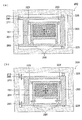
次に、本発明の第3の実施の形態について、図8を用いて説明する。図8は、本発明における移動機構の第3の実施の形態を示す模式図で、図8(a)は移動前の状態を示す平面図、図8(b)は移動後の状態を示す平面図である。第1および第2の実施の形態では被移動部151をZ方向に平行移動させる機構について示したが、本第3の実施の形態では、平面状の被移動部151を、その平面方向に移動させる機構について説明する。
Next, a third embodiment of the present invention will be described with reference to FIG. 8A and 8B are schematic views showing a third embodiment of the moving mechanism according to the present invention. FIG. 8A is a plan view showing a state before the movement, and FIG. 8B is a plane showing a state after the movement. FIG. In the first and second embodiments, the mechanism for moving the moved
図8(a)において、移動機構200は、固定部211、被移動部151、第1の移動部261、2本の第1の梁293、2個の第1の駆動部223、第2の移動部263、2本の第2の梁295および2個の第2の駆動部225等で構成される。
8A, the moving
第1の移動部261は剛性を持つ矩形の平板であり、矩形の1辺の端面の両端2カ所で2本の第1の梁293の一端と接続されている。2本の第1の梁293の他端は、第1の移動部261と2本の第1の梁293とを囲むロの字状の剛性を持つ平板である第2の移動部263の1辺と接続されている。第2の移動部263は、その1辺の端面の両端2カ所で2本の第2の梁295の一端と接続されている。2本の第2の梁295の他端は固定部211の凹部213の内壁側面に当接され、接着等により固定されている。上述した第1の移動部261、2本の第1の梁293、第2の移動部263および2本の第2の梁295は一体に形成されている。
The first moving
2個の第1の駆動部223は、図8に示すように、第1の移動部261と第2の移動部263との2カ所の隙間に、図8のX方向に駆動力が互いに反対方向に作用するように配置される。2個の第2の駆動部225は、図8に示すように、第2の移動部263と固定部211の内壁側面との2カ所の隙間に、図8のY方向に駆動力が互いに反対方向に作用するように配置される。
As shown in FIG. 8, the two
被移動部151は、第1および第2の実施の形態と同様に、例えば撮像素子、加速度センサ、位置センサ、温度センサ等のセンサ類や、それらと周辺回路とを集積した集積回路等のような半導体製造プロセスで製造される電子回路であり、第1の移動部261の表面上に搭載され、少なくともその一部が第1の移動部261に固定されている。固定方法については後述する。
As in the first and second embodiments, the moved
被移動部151、第1の移動部261、2本の第1の梁293、2個の第1の駆動部223、第2の移動部263、2本の第2の梁295および2個の第2の駆動部225は全て固定部111の凹部113内に収納されており、図示しないカバーガラス等の封止部材によって封止されている。これによって、被移動部151の表面へのゴミの付着、2本の第1の梁293および2本の第2の梁295への異物の噛み込みや、湿度による各部の腐食等を防止することができる。
The
図8(b)において、図示しない外部回路によって、2個の第1の駆動部223の一方が伸張し、他方が収縮するような駆動信号が印加されると、2本の第1の梁293が平行板バネとして作用して第1の移動部261がX方向に平行移動される。
In FIG. 8B, when a driving signal is applied such that one of the two
同様に、図示しない外部回路によって、2個の第2の駆動部225の一方が伸張し、他方が収縮するような駆動信号が印加されると、2本の第2の梁295が平行板バネとして作用して、第1の移動部261および第2の移動部263がY方向に平行移動される。
Similarly, when a drive signal is applied so that one of the two
上述した2個の第1の駆動部223および2個の第2の駆動部225への駆動信号の印加を同時に行うことで、第1の移動部261上に固定された被駆動部151を、図のXY面内でのXおよびY方向に平行移動することができる。
By simultaneously applying the drive signals to the two
上述したように、本発明の第3の実施の形態によれば、第1の駆動部223あるいは第2の駆動部225の伸縮によって第1の移動部261をX、Y方向に移動させる際に、2本の第1の梁293あるいは2本の第2の梁295のバネ性の釣り合いにより、移動部261を傾くことなしにX、Y方向に平行に移動させることができ、移動部261の面上に搭載された被移動部151も、傾くことなしにX、Y方向に平行に移動させることができる。
As described above, according to the third embodiment of the present invention, when the first moving
さらに、被移動部151、第1の移動部261、2本の第1の梁293、2個の第1の駆動部223、第2の移動部263、2本の第2の梁295および2個の第2の駆動部225が全て固定部111の凹部113内に収納されており、カバーガラス等の封止部材によって封止されているので、被移動部151の表面へのゴミの付着、2本の第1の梁293および2本の第2の梁295への異物の噛み込みや、湿度による各部の腐食等を防止することができる。
Furthermore, the
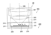
続いて、上述した第3の実施の形態の移動機構200を備えた撮像装置の1例を、図9を用いて説明する。図9は、上述した第3の実施の形態の移動機構200を備えた撮像装置20の1例を示す断面図である。
Next, an example of an imaging apparatus including the moving
図9において、撮像素子である被移動部151、第1の移動部261、2本の第1の梁293、2個の第1の駆動部223、第2の移動部263、2本の第2の梁295および2個の第2の駆動部225は、撮像素子パッケージである固定部211の凹部213内に収納されている。固定部211の開口部は、赤外光(IR)カットフィルタである封止部材131によって封止されており、上述したMCUである撮像装置20の手ブレ補正ユニットである移動機構200を構成している。
In FIG. 9, a moving
移動機構200の上には、鏡胴311内に撮像レンズ301と303とを固定して収納した撮像装置20の撮像光学系300が、例えば、移動機構200が駆動されていない状態で、撮像光学系300の光軸305が被移動部151の画素部の中心に一致するように配置されている。固定部211と鏡胴311とは、例えば接着等により接続され、MCUである撮像装置20を構成している。
On the moving
撮像装置20の手ブレ補正動作時には、例えば図示しない手ブレ検出部からの手ブレ信号に基づいて、図示しない手ブレ補正回路によって、被移動部151の移動方向と移動量の決定が行われる。手ブレ補正回路によって決定された移動方向と移動量に基づいて、図示しない外部駆動回路からの信号により、2個の第1の駆動部223および2個の第2の駆動部225駆動され、図8に述べた原理によって被移動部151がXおよびY方向に平行移動される。これによって、撮像光学系300と撮像素子である被移動部151との、光軸305に垂直な方向の相対位置関係が変更され、撮像装置20の手ブレ補正動作が行われる。
At the time of camera shake correction operation of the
上述したように、第3の実施の形態の移動機構200を備えた撮像装置20によれば、第3の実施の形態の移動機構200によって、撮像素子である被移動部151を光軸305に対して傾くことなく、光軸305に垂直な面内で平行に移動させることができるので、画像の片ボケや傾き等のない高画質な撮像装置10を提供することができる。
As described above, according to the
さらに、移動機構200が固定部211と封止部材131とで封止されているので、被移動部151の表面へのゴミの付着、2本の第1の梁293および2本の第2の梁295への異物の噛み込みや、湿度による各部の腐食等を防止することができ、信頼性の高い撮像装置10を提供することができる。
Furthermore, since the moving
上述した第1あるいは第2の実施の形態と第3の実施の形態とを組み合わせれば、撮像素子である被移動部151を撮像光学系300の光軸305に垂直な面内(X方向およびY方向)と光軸305方向(Z方向)の3方向に自由に平行移動させることができ、手ブレ補正とオートフォーカスの両機能を高性能に達成することができる。
By combining the first or second embodiment and the third embodiment described above, the moved
ここで、第1乃至第3の実施の形態における移動部や梁のような構造体の形成方法について、図10を用いて説明する。図10は、図1に示した第1の実施の形態における移動部161、4つの梁171、スリット173および4つの梁支持部175の形成方法を示す模式図である。ここで用いられる技術は、半導体製造プロセスを応用した所謂微細加工技術(以下、MEMS技術と言う)である。
Here, a method of forming a structure such as a moving part or a beam in the first to third embodiments will be described with reference to FIG. FIG. 10 is a schematic diagram showing a method of forming the moving
図10(a)において、シリコン(Si)からなる基板401上に犠牲層403と呼ばれるシリコンの酸化膜(SiO2)を選択的に積む。図10(b)において、基板401と犠牲層403との上に、不純物を高濃度にドープされて導電性を持つシリコン(Si)からなる構造層405を積み上げる。
In FIG. 10A, a silicon oxide film (SiO 2 ) called a
図10(c)において、構造層405を犠牲層403まで選択的にエッチングし、移動部161、4つの梁171およびスリット173を形成する。図10(d)において、基板401を犠牲層403まで選択的にエッチングし、4つの梁支持部175を形成する。図10(e)において、最後に犠牲層403を犠牲層エッチング技術により取り除くことで、図1に示した第1の実施の形態における移動部161、4つの梁171、スリット173および4つの梁支持部175を形成することができる。
In FIG. 10C, the
図4に示した第2の実施の形態および図8に示した第3の実施の形態における移動部および梁についても、同様の方法によって形成が可能である。 The moving part and the beam in the second embodiment shown in FIG. 4 and the third embodiment shown in FIG. 8 can also be formed by the same method.
次に、本実施の形態における被移動部151を移動部161に固定する方法について、説明する。上述したように、本実施の形態における被移動部151は、例えば撮像素子、加速度センサ、位置センサ、温度センサ等のセンサ類や、それらと周辺回路とを集積した集積回路等のようなシリコン(Si)を主材料として半導体製造プロセスで作製される電子回路である。また移動部161も、図10で説明したように、シリコン(Si)を主材料としてMEMS技術によって作製される。
Next, a method for fixing the moved
このように、シリコン(Si)等を素材に半導体製造プロセスやMEMS技術で作製されたチップや部品同士を接合する技術として、直接接合技術がある。直接接合技術とは、接着剤を用いずに、同種材料間の表面間引力を利用してチップや部品同士を直接接合する方法であり、接合後の強度や歪や傾きの少なさ、接合の簡便性、省スペース等に優れた方法である。本実施の形態においては、被移動部151も移動部161もシリコン(Si)からできていることから、直接接合技術による接合が可能となり上述したメリットを得ることができる。
As described above, there is a direct bonding technique as a technique for bonding chips or components manufactured by a semiconductor manufacturing process or a MEMS technique using silicon (Si) or the like as a material. Direct bonding technology is a method in which chips and parts are directly bonded to each other using the attractive force between the surfaces of the same kind of material without using an adhesive, and the strength, distortion and inclination after bonding, This method is excellent in simplicity, space saving, and the like. In the present embodiment, since both the moved
なお、直接接合技術については、例えば[独立行政法人産業技術総合研究所「ウェハ直接接合技術」http://staff.aist.go.jp/takagi.hideki/waferbonding.html(平成19年8月27日検索)]等に詳述されている。 As for the direct bonding technology, for example, [National Institute of Advanced Industrial Science and Technology “Wafer Direct Bonding Technology” http: // stuff. aist. go. jp / takagi. hideki / waferbonding. html (searched on August 27, 2007)] and the like.
上述したように、シリコン(Si)等を素材にチップや部品を半導体製造プロセスやMEMS技術で作製することで、チップや部品を直接接合技術によって接合することができ、接合後の強度や歪や傾きの少なさ、接合の簡便性、省スペース等のメリットを得ることができる。 As described above, by manufacturing chips and components using silicon (Si) or the like by a semiconductor manufacturing process or MEMS technology, the chips or components can be bonded by direct bonding technology, and the strength and strain after bonding can be increased. Advantages such as a small inclination, simple joining, and space saving can be obtained.
最後に、本発明における駆動部121について述べる。本発明においては、駆動部121は、例えば第1および第2の実施の形態のように移動部161と固定部111との間に、あるいは第3の実施の形態のように、第1の移動部261と第2の移動部263との隙間や第2の移動部263と固定部211の内壁側面との隙間に配置できさえすれば、アクチュエータの種類に依存するものではなく、上述した積層型圧電素子、静電アクチュエータ等をはじめとして、多種多様なアクチュエータを使用することができる。
Finally, the
以下に、[長田他「ソフトアクチュエータ開発の最前線(人工筋肉の実現をめざして)」(株)エヌ・ティー・エス、2004年10月1日初版発行]に記されているアクチュエータから、本発明に使用可能なアクチュエータの何例かを挙げる。 From the actuators described in [Nagata et al., “Frontiers of Soft Actuator Development (Aiming at Realization of Artificial Muscle)” (NTS, Inc., first published on October 1, 2004)] Here are some examples of actuators that can be used in the invention.
(1)イオン伝導アクチュエータ(同上96頁)
(2)導電性高分子アクチュエータ(同上96頁)
(3)電場駆動型高分子アクチュエータ(同上207頁図12)
(4)液晶ゲルアクチュエータ(同上217頁)
(5)空気圧ソフトアクチュエータ(同上294頁)
(6)電場駆動型メタル・アクチュエータ(同上349頁図11)
なお、ここに示したアクチュエータはほんの1例であり、本発明は上述したアクチュエータに制限されるものではない。
(1) Ion conduction actuator (p. 96)
(2) Conductive polymer actuator (p. 96)
(3) Electric field driven polymer actuator (Fig. 12 on page 207)
(4) Liquid crystal gel actuator (Id. 217)
(5) Pneumatic soft actuator (page 294)
(6) Electric field drive type metal actuator (Fig. 11 on page 349)
The actuator shown here is only an example, and the present invention is not limited to the actuator described above.
アクチュエータは、その材質にもよるが、シリコン(Si)系を主材料とするものであれば、上述した直接接合技術を用いて接合し、あるいはシリコン(Si)の構造部に蒸着等の手法でアクチュエータ自体を形成することもできる。また、異質な材料であれば、接着等の方法で取り付けることができる。 Depending on the material of the actuator, if the main material is silicon (Si), the actuator can be joined using the direct joining technique described above, or it can be deposited on the silicon (Si) structure by means such as vapor deposition. The actuator itself can also be formed. Moreover, if it is a different material, it can attach by methods, such as adhesion | attachment.
以上に述べたように、本発明によれば、バネ性を備えた梁によって移動部と固定部とを接続し、駆動部によって移動部を移動させることで、複数の駆動部を用いることなく、駆動部自体の駆動に依存することもなく、移動部を駆動部の駆動方向と平行に移動させることのできる移動機構および該移動機構を用いた撮像装置を提供することができる。 As described above, according to the present invention, the moving unit and the fixed unit are connected by a beam having spring properties, and the moving unit is moved by the driving unit, without using a plurality of driving units. It is possible to provide a moving mechanism capable of moving the moving unit in parallel with the driving direction of the driving unit and an imaging apparatus using the moving mechanism without depending on the driving of the driving unit itself.
尚、本発明に係る移動機構および撮像装置を構成する各構成の細部構成および細部動作に関しては、本発明の趣旨を逸脱することのない範囲で適宜変更可能である。 The detailed configuration and detailed operation of each component constituting the moving mechanism and the imaging apparatus according to the present invention can be changed as appropriate without departing from the spirit of the present invention.
10 撮像装置
100 移動機構(オートフォーカスユニット)
111 固定部
113 (固定部の)凹部
115 突起部
121 駆動部
131 封止部材
151 被移動部
151a ボンディングパッド
155 ボンディングワイヤ
161 移動部
161a ボンディングパッド
161b 配線
171 梁
173 スリット
175 梁支持部
181 梁
183 梁
20 撮像装置
200 移動機構(手ブレ補正ユニット)
211 固定部
213 (固定部の)凹部
223 第1の駆動部
225 第2の駆動部
261 第1の移動部
263 第2の移動部
293 第1の梁
295 第2の梁
300 撮像光学系
301 撮像レンズ
303 撮像レンズ
305 (撮像光学系の)光軸
311 鏡胴
401 基板
403 犠牲層
405 構造層
10
DESCRIPTION OF
211
Claims (12)
被移動部を搭載するための平板状の移動部と、
前記移動部の前記被移動部を搭載した面の裏面と前記凹部の底面との間に設けられ、前記移動部を前記凹部の底面に垂直な方向に移動させる駆動部と、
一端が前記移動部に固定され、他端が前記凹部の側面に固定され、前記移動部が移動される方向にバネ性が付与されている複数の梁を備えたことを特徴とする移動機構。 A fixed portion having a recess composed of at least a bottom surface and a side surface;
A plate-shaped moving part for mounting the moved part;
A drive unit that is provided between the back surface of the surface of the moving unit on which the moving unit is mounted and the bottom surface of the recess, and moves the moving unit in a direction perpendicular to the bottom surface of the recess;
A moving mechanism comprising: a plurality of beams having one end fixed to the moving portion, the other end fixed to a side surface of the recess, and spring properties in a direction in which the moving portion is moved.
複数の前記梁と前記移動部の端面と前記凹部の複数の前記梁が固定される側面とが平行四辺形を形成することを特徴とする請求項1に記載の移動機構。 The plurality of beams are cantilevered support beams whose one ends are fixed at different positions in the thickness direction of the same end surface of the moving unit,
The moving mechanism according to claim 1, wherein the plurality of beams, end surfaces of the moving unit, and side surfaces to which the plurality of beams of the concave portion are fixed form a parallelogram.
前記移動部と複数の前記梁とは前記被移動部と同一の主材料で形成され、
前記被移動部は、少なくともその一部が前記移動部に直接接合技術により接合されていることを特徴とする請求項1乃至3の何れか1項に記載の移動機構。 The moved part is an electronic circuit part formed in a semiconductor manufacturing process,
The moving part and the plurality of beams are formed of the same main material as the moved part,
The moving mechanism according to any one of claims 1 to 3, wherein at least a part of the moved portion is joined to the moving portion by a direct joining technique.
前記凹部を覆う封止部を備え、
前記凹部は、前記固定部と前記封止部とにより密封されていることを特徴とする請求項1乃至4の何れか1項に記載の移動機構。 The moved portion, the moving portion, and the plurality of beams are housed in the recess,
A sealing portion covering the recess,
5. The moving mechanism according to claim 1, wherein the concave portion is sealed by the fixing portion and the sealing portion.
前記第1の移動部と同一面内で、前記第1の移動部の少なくとも3方を囲むように設けられた第1の固定部と、
前記第1の移動部と前記第1の固定部との間に配置され、前記第1の移動部を前記第1の固定部に対して同一面内で移動させる複数の第1の駆動部と
一端が前記第1の移動部の同一端面に固定され、他端が前記第1の固定部に固定され、前記第1の移動部が移動される方向にバネ性が付与された複数の第1の梁と、
少なくとも底面と側面とからなる凹部を有する第2の固定部と、
前記第1の固定部と前記第2の固定部との間に配置され、前記第1の固定部を前記第2の固定部に対して同一面内で前記第1の移動部の移動方向と垂直な方向に移動させる複数の第2の駆動部と、
一端が前記第1の固定部の同一端面に固定され、他端が前記第2の固定部の側面に固定され、前記第1の固定部が移動される方向にバネ性が付与された複数の第2の梁とを備えたことを特徴とする移動機構。 A flat plate-like first moving part for mounting the moved part;
A first fixed portion provided to surround at least three sides of the first moving portion in the same plane as the first moving portion;
A plurality of first drive units disposed between the first moving unit and the first fixed unit, the first driving unit moving the first moving unit with respect to the first fixed unit in the same plane; One end is fixed to the same end surface of the first moving part, the other end is fixed to the first fixing part, and a plurality of first elements are provided with a spring property in a direction in which the first moving part is moved. And
A second fixing portion having a recess composed of at least a bottom surface and a side surface;
The first fixing portion is disposed between the first fixing portion and the second fixing portion, and the first fixing portion is arranged in the same plane with respect to the second fixing portion, and the moving direction of the first moving portion is A plurality of second drive units that move in a vertical direction;
One end is fixed to the same end surface of the first fixing portion, the other end is fixed to a side surface of the second fixing portion, and a plurality of spring properties are provided in a direction in which the first fixing portion is moved. A moving mechanism comprising a second beam.
前記第1の移動部、前記第1の固定部、複数の前記第1の梁、および複数の前記第2の梁は前記被移動部と同一の主材料で形成され、
前記被移動部は、少なくともその一部が前記第1の移動部に直接接合技術により接合されていることを特徴とする請求項7に記載の移動機構。 The moved part is an electronic circuit part formed in a semiconductor manufacturing process,
The first moving part, the first fixed part, the plurality of first beams, and the plurality of second beams are formed of the same main material as the moved part,
The moving mechanism according to claim 7, wherein at least a part of the moved portion is joined to the first moving portion by a direct joining technique.
前記凹部を覆う封止部を備え、
前記凹部は、前記固定部と前記封止部とにより密封されていることを特徴とする請求項7または8に記載の移動機構。 The moved portion, the first moving portion, the first fixed portion, the plurality of first drive portions, the plurality of first beams, the plurality of second drive portions, and the plurality of second portions. Is housed in the recess,
A sealing portion covering the recess,
The movement mechanism according to claim 7 or 8, wherein the concave portion is sealed by the fixing portion and the sealing portion.
請求項1乃至11の何れか1項に記載の移動機構とを備え、
前記被移動部は撮像センサであることを特徴とする撮像装置。 An imaging optical system;
A moving mechanism according to any one of claims 1 to 11,
An image pickup apparatus, wherein the moved part is an image sensor.
Priority Applications (1)
| Application Number | Priority Date | Filing Date | Title |
|---|---|---|---|
| JP2007239055A JP2009071663A (en) | 2007-09-14 | 2007-09-14 | Movement mechanism and imaging apparatus |
Applications Claiming Priority (1)
| Application Number | Priority Date | Filing Date | Title |
|---|---|---|---|
| JP2007239055A JP2009071663A (en) | 2007-09-14 | 2007-09-14 | Movement mechanism and imaging apparatus |
Publications (1)
| Publication Number | Publication Date |
|---|---|
| JP2009071663A true JP2009071663A (en) | 2009-04-02 |
Family
ID=40607451
Family Applications (1)
| Application Number | Title | Priority Date | Filing Date |
|---|---|---|---|
| JP2007239055A Pending JP2009071663A (en) | 2007-09-14 | 2007-09-14 | Movement mechanism and imaging apparatus |
Country Status (1)
| Country | Link |
|---|---|
| JP (1) | JP2009071663A (en) |
Cited By (3)
| Publication number | Priority date | Publication date | Assignee | Title |
|---|---|---|---|---|
| KR20120125449A (en) * | 2012-10-29 | 2012-11-15 | 엘지이노텍 주식회사 | Mems actuator and camera module comprising the same |
| JP2016001912A (en) * | 2009-06-15 | 2016-01-07 | アイデンティクス・インコーポレーテッドIdentix Incorporated | Method for generating fingerprint image |
| JP2021099417A (en) * | 2019-12-20 | 2021-07-01 | ローム株式会社 | Camera module |
-
2007
- 2007-09-14 JP JP2007239055A patent/JP2009071663A/en active Pending
Cited By (5)
| Publication number | Priority date | Publication date | Assignee | Title |
|---|---|---|---|---|
| JP2016001912A (en) * | 2009-06-15 | 2016-01-07 | アイデンティクス・インコーポレーテッドIdentix Incorporated | Method for generating fingerprint image |
| KR20120125449A (en) * | 2012-10-29 | 2012-11-15 | 엘지이노텍 주식회사 | Mems actuator and camera module comprising the same |
| KR101721894B1 (en) * | 2012-10-29 | 2017-03-31 | 디지털옵틱스 코포레이션 | Mems actuator and camera module comprising the same |
| JP2021099417A (en) * | 2019-12-20 | 2021-07-01 | ローム株式会社 | Camera module |
| JP7426816B2 (en) | 2019-12-20 | 2024-02-02 | ローム株式会社 | The camera module |
Similar Documents
| Publication | Publication Date | Title |
|---|---|---|
| US12132420B2 (en) | MEMS actuator package architecture | |
| US8248497B2 (en) | Image sensor device with movable sensor | |
| US7489340B2 (en) | Optical image stabilizer for camera lens assembly | |
| CN101420526B (en) | Image sensor bearing device and camera module group | |
| CN107948532B (en) | Optical image stabilization system, imaging device and electronic device | |
| US8730599B2 (en) | Piezoelectric and MEMS actuator | |
| US20200363629A1 (en) | Process for manufacturing a mems micromirror device, and associated device | |
| CN212723526U (en) | MEMS actuators | |
| KR101158200B1 (en) | Optical Image Stabilizer and Method of manufacturing the same | |
| CN104203805B (en) | MEMS device and apparatus for compensating jitter | |
| KR101075710B1 (en) | Optical image stabilization device and manufacturing method thereof | |
| CN112781829A (en) | Adjustable frequency spectrum sensing device, out-of-plane motion motor and preparation method thereof | |
| JP5217489B2 (en) | Drive mechanism | |
| JP2009071663A (en) | Movement mechanism and imaging apparatus | |
| KR20150002220A (en) | MICRO ELECTRO MECHANICAL SYSTEMS DEVICE and CAMERA MODULE HAVING THE SAME | |
| US8000590B2 (en) | Driving apparatus, image capturing unit, and image capturing apparatus | |
| KR102029783B1 (en) | Micro electro mechanical systems device and apparatus for compensating tremble | |
| US12493180B2 (en) | Microelectromechanical mirror device with piezoelectric actuation having improved stress resistance | |
| JP2009034779A (en) | Driving device, imaging unit, imaging device, and manufacturing method of driving device | |
| KR20140116737A (en) | Camera Module | |
| JP2006261141A (en) | Piezoelectric actuator and image input device | |
| JP5372354B2 (en) | Piezoelectric actuator and electronic device using the piezoelectric actuator | |
| KR20140117029A (en) | Camera Module | |
| KR102107584B1 (en) | Micro electro mechanical systems device |