JP2009070134A - Data format conversion method, data format conversion program, recording medium recording this program, and drawing creation device - Google Patents
Data format conversion method, data format conversion program, recording medium recording this program, and drawing creation device Download PDFInfo
- Publication number
- JP2009070134A JP2009070134A JP2007237800A JP2007237800A JP2009070134A JP 2009070134 A JP2009070134 A JP 2009070134A JP 2007237800 A JP2007237800 A JP 2007237800A JP 2007237800 A JP2007237800 A JP 2007237800A JP 2009070134 A JP2009070134 A JP 2009070134A
- Authority
- JP
- Japan
- Prior art keywords
- screen
- data
- attribute
- editor
- program
- Prior art date
- Legal status (The legal status is an assumption and is not a legal conclusion. Google has not performed a legal analysis and makes no representation as to the accuracy of the status listed.)
- Pending
Links
Images

Abstract
Description
本発明は、図面作成プログラムによって作成された図面データをプログラマブル表示器に表示する画面を作成する画面作成プログラムで扱える形式に変換するデータ形式変換方法、データ形式変換プログラムおよびそれを記録した記録媒体、ならびに図面作成装置に関するものである。 The present invention relates to a data format conversion method for converting drawing data created by a drawing creation program into a format that can be handled by a screen creation program for creating a screen to be displayed on a programmable display, a data format conversion program, and a recording medium recording the same, The present invention also relates to a drawing creation apparatus.
グラフィックスソフトウェアは、図形や絵を描くソフトウェアとして一般に普及している。特に、ドローイングソフトウェアは、線の座標、角度、方向などの数値データとして直線や曲線を表すので、描いた図形に移動、反転、拡大、縮小などの処理を施すことができる。 Graphics software is generally popular as software for drawing figures and pictures. In particular, the drawing software expresses a straight line or a curve as numerical data such as the coordinates, angle, and direction of the line, so that the drawn figure can be subjected to processing such as movement, inversion, enlargement, and reduction.
ドローイングソフトウェアは、上記のような図形の加工が容易にできることや、各種の部品を利用できる機能を備え、その部品を用いて多彩な図を作成できることから、各種の図面の作成に用いられることが多い。例えば、階段、ドア、窓などの部品を利用することにより、間取り図を容易に作成することができる。 Drawing software can be used to create various types of drawings because it can easily process figures as described above, and has a function that allows you to use various parts. Many. For example, a floor plan can be easily created by using parts such as stairs, doors, and windows.
ところで、近年のビルオートメーション(BA)においては、各フロアの間取り図(フロア図)を作成して、各フロアの管理に利用している。このようなフロア図も、上記のドローイングソフトウェアで作成されることが多い。 By the way, in recent building automation (BA), a floor plan (floor diagram) of each floor is created and used for management of each floor. Such a floor plan is often created by the above drawing software.
また、BAは、管理室などでビル設備の監視・制御を行うために、コンピュータを中心とする監視・制御システムを中核として構築される。このような監視・制御システムにおいて、近年、プログラマブル表示器の導入が進められている。 The BA is built around a monitoring / control system centered on a computer in order to monitor / control building facilities in a management room or the like. In such a monitoring / control system, introduction of a programmable display device has been promoted in recent years.
プログラマブル表示器は、プログラマブルロジックコントローラ(PLC)などのコントローラとの通信インターフェースを備えており、コントローラの稼働状況を表示したり、コントローラに対する制御指示を与えるための操作入力を画面から受け付けたりする機能を備えた操作型表示器である。一般に、プログラマブル表示器は、グラフィック表示機能を有するので、操作盤、スイッチ、表示灯等を表示することができ、制御システムにおける操作端末としての役割を果たす。このような制御システムにおいて、各コントローラの稼働状況などの表示やコントローラへの制御指示は、コントローラ付近に配置されたプログラマブル表示器によって行われる。 The programmable display has a communication interface with a controller such as a programmable logic controller (PLC), and has a function of displaying the operation status of the controller and receiving an operation input for giving a control instruction to the controller from the screen. It is an operation type display provided. In general, since the programmable display has a graphic display function, it can display an operation panel, a switch, an indicator lamp, and the like, and serves as an operation terminal in the control system. In such a control system, display of the operating status of each controller and control instructions to the controller are performed by a programmable display arranged near the controller.
プログラマブル表示器に表示される画面は、画面作成ソフトウェアを用いて作成される。この画面作成ソフトウェアは、スイッチ、ランプなどが画像化された部品を画面上に配置していくことによって画面を作成する。また、画面作成ソフトウェアは、画面に配置した部品への属性の設定、これらの部品と対応する機器との対応付け、作成した画面のプログラマブル表示器への転送などの多岐にわたる機能を備えている。さらに、画面作成ソフトウェアは、ユーザが所望の図形を作成できるように線画作成機能も備えている。 The screen displayed on the programmable display is created using screen creation software. This screen creation software creates a screen by arranging parts on which images of switches, lamps and the like are imaged. Further, the screen creation software has various functions such as setting attributes for components arranged on the screen, associating these components with corresponding devices, and transferring the created screen to a programmable display. Furthermore, the screen creation software has a line drawing creation function so that the user can create a desired figure.
プログラマブル表示器は、上記のような特徴から監視・制御に適しており、ビルオートメーションだけではなく、各種の分野への利用が進められている。
例えば、BAにおいて、各フロアの照明や空調の監視・制御をプログラマブル表示器を用いて行おうとした場合、上記の画面作成ソフトウェアを用いて、各フロアの図を画面として作成する必要がある。ところが、画面作成ソフトウェアは、上記のように多岐にわたる機能を備えているため、ソフトウェアのサイズなどを鑑みて、線画作成機能については、ドローイングソフトウェアなどの専用のグラフィックスソフトウェアのように充実させることは困難である。 For example, in BA, when it is attempted to monitor and control the lighting and air conditioning of each floor using a programmable display, it is necessary to create a diagram of each floor as a screen using the above-described screen creation software. However, since the screen creation software has various functions as described above, considering the size of the software, the line drawing creation function cannot be enhanced like dedicated graphics software such as drawing software. Have difficulty.
このため、画面作成ソフトウェアで作成したフロア図は、ドローイングソフトウェアで作成したフロア図と比べて、表現に乏しいものとなる。また、ドローイングソフトウェアで作成した図は、データ形式が画面作成ソフトウェアで作成する画面と異なるため、そのまま画面作成ソフトウェアで利用することができない。したがって、ドローイングソフトウェアでフロア図を作成しても、別途、画面作成ソフトウェアでフロア図を画面に作成しなければならず、画面作成作業が非効率的である。 For this reason, the floor diagram created by the screen creation software is less expressive than the floor diagram created by the drawing software. In addition, since the diagram created with the drawing software has a different data format from the screen created with the screen creation software, it cannot be used directly with the screen creation software. Therefore, even if the floor diagram is created with the drawing software, the floor diagram must be separately created on the screen with the screen creation software, and the screen creation work is inefficient.
また、ドローイングソフトウェアで作成した図をイメージとして取り込んで、画面作成ソフトウェアで作成する画面に貼り付けることができるが、取り込んだ図がイメージであるため、画面作成ソフトウェアで図を線画として扱うことができない。このため、図の大きさや図を構成する線の種類を変更するなどの加工をすることができず、画面に合わせて所望に図を編集することができない。 In addition, a drawing created with drawing software can be imported as an image and pasted to a screen created with screen creation software. However, since the imported diagram is an image, the screen creation software cannot handle the diagram as a line drawing. . For this reason, it is not possible to perform processing such as changing the size of the figure or the type of lines constituting the figure, and the figure cannot be edited as desired according to the screen.
特許文献1には、画面データを形式の異なる他の画面データに変換することが記載されている。これをドローイングソフトウェアで作成したデータの形式を画面作成ソフトウェアで作成したデータの形式に変換することに適用することが考えられる。しかしながら、特許文献1には、画面に配置されている部品を解析して形式を変換することは記載されているが、ドローイングソフトウェアで作成する線画のデータを変換することは開示されていない。このため、特許文献1の変換方法をそのまま、上記のようなデータ変換に適用することはできない。
本発明は、上記の問題点に鑑みてなされたものであり、その目的は、ドローイングソフトウェアで作成されたデータを画面作成プログラムで加工可能に扱えるようにすることにある。 The present invention has been made in view of the above problems, and an object of the present invention is to make it possible to process data created by drawing software so that it can be processed by a screen creation program.
本発明に係るデータ形式変換方法は、図面を作成する図面作成プログラムで作成された図面データの属性とプログラマブル表示器に表示する画面を作成する画面作成プログラムで作成された画面データの属性とを対応付けて記憶する対応テーブルを参照して、前記図面データの属性を対応する前記画面データの属性に変換することを特徴としている。 The data format conversion method according to the present invention corresponds to the attribute of drawing data created by a drawing creation program for creating a drawing and the attribute of screen data created by a screen creation program for creating a screen to be displayed on a programmable display. The attribute of the drawing data is converted into the attribute of the corresponding screen data with reference to the correspondence table to be added and stored.
本発明に係る図面作成装置は、図面を作成する図面作成プログラムで作成された図面データの属性とプログラマブル表示器に表示する画面を作成する画面作成プログラムで作成された画面データの属性とを対応付けて記憶する対応テーブルと、前記図面データの属性を前記対応テーブルを参照して対応する前記画面データの属性に変換するデータ変換手段とを備えていることを特徴としている。 The drawing creation apparatus according to the present invention associates an attribute of drawing data created by a drawing creation program for creating a drawing with an attribute of screen data created by a screen creation program for creating a screen to be displayed on a programmable display. And a data conversion means for converting the attribute of the drawing data into the attribute of the corresponding screen data with reference to the correspondence table.
上記の方法および装置では、図面作成プログラムで作成された図面データの属性が、対応テーブルを参照することにより、対応する画面データの属性に変換される。これにより、変換後の属性からなるデータは、画面作成プログラムで扱うことができる形式となるため、画面作成プログラムで編集可能となる。 In the above method and apparatus, the attribute of the drawing data created by the drawing creation program is converted into the attribute of the corresponding screen data by referring to the correspondence table. As a result, the data consisting of the converted attributes is in a format that can be handled by the screen creation program, and can therefore be edited by the screen creation program.
前記データ形式変換方法は、前記図面作成プログラムが図面を作成する領域として表示する描画エリアのサイズを前記画面のサイズに設定することが好ましい。 In the data format conversion method, it is preferable that a size of a drawing area displayed as an area for creating a drawing by the drawing creating program is set to the size of the screen.
また、前記図面作成装置は、前記図面作成プログラムが図面を作成する領域として表示する描画エリアのサイズを前記画面のサイズに設定するサイズ設定手段を備えていることが好ましい。 The drawing creation apparatus preferably includes size setting means for setting a size of a drawing area displayed as a drawing creation area by the drawing creation program to the size of the screen.
これにより、変換後のデータを画面作成プログラムで編集するとき、画面として表示されるサイズを調整する必要がない。 Thus, when the converted data is edited by the screen creation program, it is not necessary to adjust the size displayed as the screen.
前記データ形式変換方法および前記図面作成装置において、前記対応テーブルは、図面データの属性と一致する属性を前記画面作成プログラムが扱えないとき、当該図面データの属性に近似する属性を対応付けることが好ましい。 In the data format conversion method and the drawing creation apparatus, it is preferable that the correspondence table associates an attribute that approximates an attribute of the drawing data when the screen creation program cannot handle an attribute that matches the attribute of the drawing data.
これにより、図面作成プログラムのデータの属性から変換可能なデータを増加させ、図面作成プログラムで作成された図面の情報量をできるだけ多く画面作成プログラムで作成する画面に反映させることができる。 As a result, it is possible to increase the amount of data that can be converted from the data attributes of the drawing creation program, and to reflect as much information amount of the drawing created by the drawing creation program as possible on the screen created by the screen creation program.
本発明のデータ形式変換プログラムは、前述のデータ形式変換方法の手順をコンピュータに実行させるためのプログラムである。このデータ形式変換プログラムは、コンピュータ読み取り可能な記録媒体に記録されていてもよい。 The data format conversion program of the present invention is a program for causing a computer to execute the procedure of the data format conversion method described above. This data format conversion program may be recorded on a computer-readable recording medium.
このように、図面作成プログラムをコンピュータに読み取らせて実行させることにより、前記データ形式変換方法をコンピュータにおいて実現することができる。 As described above, the data format conversion method can be realized in the computer by causing the computer to read and execute the drawing creation program.
本発明に係るデータ形式変換方法および図面作成装置は、以上のように、図面を作成する図面作成プログラムで作成された図面データの属性とプログラマブル表示器に表示する画面を作成する画面作成プログラムで作成された画面データの属性とを対応付けて記憶する対応テーブルを参照して、前記図面データの属性を対応する前記画面データの属性に変換するので、変換後の属性からなるデータを画面作成プログラムで編集することができる。したがって、図面作成プログラムですでに作成した図と同様な図を画面に描くために、画面作成プログラムで新たな画面を作成する必要がなくなり、画面作成に要する時間を短縮することができるという効果を奏する。 As described above, the data format conversion method and the drawing creation apparatus according to the present invention are created by the screen creation program for creating the screen data to be displayed on the programmable display and the attributes of the drawing data created by the drawing creation program for creating the drawing. Since the attribute of the drawing data is converted into the attribute of the corresponding screen data by referring to the correspondence table storing the attribute of the screen data associated with the screen, the screen creation program converts the data including the attribute after conversion. Can be edited. Therefore, it is not necessary to create a new screen with the screen creation program in order to draw a diagram similar to the diagram already created with the drawing creation program, and the time required for screen creation can be shortened. Play.
本発明の一実施形態について図1および図2に基づいて説明すると、以下の通りである。 An embodiment of the present invention will be described with reference to FIGS. 1 and 2 as follows.
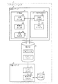
図1に示すように、本実施形態に係るエディタコンピュータ1は、図面エディタ2と、画面エディタ3とを備えている。
As shown in FIG. 1, the
エディタコンピュータ1は、CPU、メモリ(RAM、ROMなど)、外部記憶装置(ハードディスクドライブ、MOドライブなど)、表示装置および入力装置(キーボード、マウスなど)を有する汎用のパーソナルコンピュータなどで構成されている。
The
図面エディタ2は、ドローイングソフトウェアのような作図用のアプリケーションプログラムがエディタコンピュータ1にインストールされて実行されることによって実現される機能ブロックである。この図面エディタ2は、作図部4と、データ形式変換部5とを有している。
The
作図部4は、作図処理部41と、解像度設定部42と、変換指示部43とを含んでいる。
The
作図処理部41は、作図処理を行う基本機能を備えており、直線や曲線について、種類、座標、角度、方向などを数値データで表す。また、作図処理部41は、作成した図を保存するために保存部6に保存ファイルとして書き込む。保存部6は、ハードディスクドライブやフラッシュメモリなどのエディタコンピュータ1の内部または外部に設けられた記憶装置によって構成される。
The
作図処理部41は、図2に示すように、作図処理部41は、作図ウインドウ101をユーザインターフェースとして表示する。作図ウインドウ101は、作業エリア102および部品表示エリア103を有している。
As shown in FIG. 2, the
作業エリア103は、図を作成する範囲を規定する描画エリア104を表示している。この描画エリア104は、図を印刷する用紙のサイズ(A4,B4等)に規定されている。
The
部品表示エリア103は、予め用意されている各種の部品のイメージを表示している。ここから所望の部品のイメージを描画エリア103にドラッグ&ドロップの操作をされることで、当該部品を描画エリア103に配置することができる。例えば、Microsoft Visio(登録商標)では、「マスタシェイプ」と呼ばれる部品の集合体である「ステンシル」が部品表示エリア103に表示されている。ステンシルは追加することも可能である。
The parts display
解像度設定部42は、描画エリア103のサイズを画面エディタ3で作成する画面のサイズ(解像度)に設定する。解像度は、図2に示すように、複数の部品105(マスタシェイプ)として提供される。解像度設定部42は、それぞれ異なる解像度の情報を有する部品105のうち1つが、描画エリア104にドラッグ&ドロップの操作をされることで、描画エリア104のサイズを解像度に変更して設定する。例えば、320×240ドットの解像度の部品105がドラッグ&ドロップの操作をされると、例えばA4のサイズに設定されていた描画エリア104は上記の解像度のサイズに設定される。
The
なお、後述するように、データ形式変換部5が図面エディタ2の拡張機能の部分として追加される場合、上記の解像度設定部42および複数の部品105(ステンシル)も、図面エディタ2に追加されるアドオンとして構成される。
As will be described later, when the data
変換指示部43は、後述する変換処理部51によるデータ形式の変換処理の実行を指示する部分である。変換指示部43は、図示はしないが、変換処理を指示するために作画ウインドウ101に設けられたメニューやアイコンが操作されると、図示しないダイアログボックスを表示してユーザにデータ形式の変換を実行するか否かを問い合わせる。変換指示部43は、その問い合わせに対するユーザの実行指示を受けて、作図処理部41が保存部6に保存しようとするデータや、保存部6に保存されている保存ファイルのデータについての属性を後述する変換処理部51に渡す。
The
なお、データ形式変換部5が図面エディタ2の拡張機能の部分として追加される場合、変換指示部43も、上記の解像度設定部42と同様、アドオンとして構成される。
When the data
データ形式変換部5は、変換処理部51と、対応テーブル52とを有している。
The data
変換処理部5は、図面エディタ2で作成されたデータ(図面データ)を対応テーブル52を参照して、画面エディタ3で作成される画面データの形式に変換して、パッケージファイル(拡張子は.pkg)として保存部6に保存する。
The
対応テーブル52は、図面エディタ2が扱うことのできる描画オブジェクトの属性とそれに対応する画面エディタ3の描画オブジェクトの属性との対応付けをしている。表1に、対応テーブル52で対応付けられている両描画オブジェクトの属性の一部を示す。
The correspondence table 52 associates the attributes of the drawing object that can be handled by the drawing

「線の形状」は、実線、破線、点線、一点鎖線、二点鎖線などである。「角の形状」は、角の丸み(アール)であり、画面エディタ3ではサポートされていない。このため、角の形状は全て丸みのない角に対応付けられる。「線の始点・終点のサイズ」は、画面エディタ3ではサポートされていないので、線のサイズに対応付けられる。つまり、画面エディタ3では、始点・終点のサイズを変更できないので、始点・終点を太く表現することで、画面エディタ3側で大きく見せるようにする。
The “line shape” is a solid line, a broken line, a dotted line, a one-dot chain line, a two-dot chain line, or the like. The “corner shape” is a rounded corner (R) and is not supported by the
「傾斜楕円」は、2つの中心軸が水平・垂直方向に対して傾斜している楕円であり、画面エディタ3ではサポートされていないので、連続してつながる直線(連続直線)に対応付けられる。具体的には、変換処理部51は、楕円を多角形と見なして、画面エディタ3で扱うことのできる最大角数の多角形に置き換える。例えば、変換処理部51は、楕円のサイズに基づいて当該楕円の角数m(m角形)を定め、当該角数mを画面エディタ3で扱うことのできる最大の角数n(n角形)で除した数k(=m/n)ごとに楕円の角を間引いていき、楕円をn角形として表現する。また、変換処理部51は、n角形を超える多角形についても、角数を間引いてn角形に変換する。
An “inclined ellipse” is an ellipse whose two central axes are inclined with respect to the horizontal and vertical directions, and is not supported by the
また、画面エディタ3は、通常の楕円についても内部の塗り込みには対応していないので、変換処理部51は、多角形に変換して塗り込むように変換する。
Further, since the
変換処理部51は、変換指示部43により渡された図面エディタ2の描画オブジェクトの属性に対応する属性を、上記のような対応テーブル52を参照して、画面エディタ3で扱うことのできるデータ形式の属性に変換する。変換処理部51は、図面エディタ2で作成された1つの図面に含まれる全ての描画オブジェクトについての属性を上記のようにして画面エディタ3で扱うことのできる形式に変換する。また、変換処理部51は、1画面分の属性のデータと画面サイズのデータとを合わせてパッケージファイルを作成する。
The conversion processing unit 51 refers to the correspondence table 52 as described above and refers to the attribute corresponding to the drawing object attribute of the drawing
なお、データ形式変換部5は、図面エディタ2に標準的な機能として組み込まれていてもよいが、図面エディタ2のアドオン(プラグイン)として追加される機能であってもよい。データ形式変換部5は、アドオンとして提供される場合、API(Application Program Interface)からなり、DLL(Dynamic Link Library)として図面エディタ2に組み込まれる。APIとして用意される関数は、図面エディタ2の作図情報から上記の形式変換処理を行う手順を規定しており、変換指示部43からコールされる。
The data
画面エディタ3は、ファイル取込部7および画面作成処理部8を有している。
The
画面作成処理部8は、プログラマブル表示器で表示されるユーザ独自の画面(ユーザ画面)を作成できるように、スイッチ、ランプ、テンキー、各種表示器(例えば、数値表示器、メータ表示器およびグラフ表示器)などの部品、描画機能、テキスト入力機能などを備えている。部品としては、単一の機能を有する部品だけでなく、複数の機能を有する、複合スイッチ、カウンタ、タイマといった複合機能を有する部品が用意されている。部品は、ユーザが容易に選択できるようにライブラリ形式で登録されており、部品の機能に応じた処理規定情報(オブジェクトに対する手続き)が予め付与されている。描画機能は、直線や曲線の線図形を描画したり、各種のグラフ、円、四角形、多角形などの基本図形の描画および図形内の指定色や模様による塗り込みを行ったりするための機能である。
The screen
画面がプログラマブル表示器に表示されている状態では、画面における部品は、部品に対応するデバイスの状態を反映させるように表示状態が変わる。このため、画面データにおいては、各部品に対して、デバイスの状態に関するデータを格納するメモリのアドレスが関連付けられている。当該メモリは、通常、PLCなどのコントローラやプログラマブル表示器に設けられている。また、アドレスが関連付けられるのは、予め用意された部品だけではなく、ユーザが作成した図形にもアドレスを関連付けることが可能である。このように、画面データは、部品等にアドレスが関連付けられる点で、一般のコンピュータで表示されるGUI画面と異なる。そして、画面エディタ3は、このようなアドレス関連付けの機能を備えている。
In a state where the screen is displayed on the programmable display device, the display state of the component on the screen changes so as to reflect the state of the device corresponding to the component. For this reason, in the screen data, an address of a memory that stores data relating to the state of the device is associated with each component. The memory is usually provided in a controller such as a PLC or a programmable display. The address can be associated not only with a component prepared in advance, but also with a graphic created by the user. As described above, the screen data is different from a GUI screen displayed on a general computer in that an address is associated with a component or the like. The
また、画面エディタ3は、作成したユーザ画面のデータすなわち画面データをプログラマブル表示器で処理可能な形式である画面ファイルに変換して、保存部9に保存する。また、画面エディタ3は、保存された画面ファイルを保存部9から読み出して、プログラマブル表示器に転送する。ここで、上記の保存部9は、前述の保存部6と共通していてもよい。
The
ファイル取込部7は、保存部6において保存されている各種のファイルから、画面エディタ3で開くことのできるファイルを判定する。このファイル取込部7は、通常の画面データのファイル以外に、拡張子が“.pkg”の前述のパッケージファイルを画面エディタ3で開くことのできるファイルとして認識する。
The file capturing unit 7 determines a file that can be opened by the
画面エディタ3で扱うことができる画面データのファイルは、上記のように、画面データが部品等にアドレスが関連付けられているために独自の形式となっている。これに対し、図面エディタ2で作成された図面データは、上記のようなアドレスの関連付けがなされていないので、前述のようにデータ形式を変換しても、画面データのファイルと同じ形式にすることができない。このため、データ形式の変換後の図面データをパッケージファイルとして保存して、ファイル取込部7を介して画面エディタ3に取り込むようにしている。画面エディタ3に取り込むことができれば、画面エディタ3のアドレス関連付け機能によって、パッケージファイルの図面において、各図形にアドレスを関連付けることができる。
As described above, the screen data file that can be handled by the
図面エディタ2および画面エディタ部3は、エディタコンピュータ1と分離可能に構成される記録媒体に記録され、この記憶媒体からエディタコンピュータ1にインストールすることが可能である。また、エディタコンピュータ1は、図面エディタ2および画面エディタ3を備えることによりエディタ装置として機能する。
The drawing
上記の記録媒体(プログラムメディア)は、コンピュータに読み取り可能な記録媒体であり、磁気テープやカセットテープなどのテープ系、フレキシブルディスクやハードディスクなどの磁気ディスク系、CD−ROM、MO、MD、DVDなどの光ディスク系、ICカード(メモリカードを含む)、光カードなどのカード系が好適である。その他、上記のプログラムメディアは、マスクROM、EPROM、EEPROM、フラッシュROMなどによる半導体メモリを含めた固定的にプログラムを担持する媒体であってもよい。 The above-mentioned recording medium (program medium) is a computer-readable recording medium, such as a tape system such as a magnetic tape or a cassette tape, a magnetic disk system such as a flexible disk or a hard disk, CD-ROM, MO, MD, DVD, etc. A card system such as an optical disk system, an IC card (including a memory card), or an optical card is suitable. In addition, the program medium may be a medium that carries a fixed program including a semiconductor memory such as a mask ROM, EPROM, EEPROM, flash ROM, or the like.
また、エディタコンピュータ1が、インターネットを含む通信ネットワークと接続可能な環境に置かれていれば、通信ネットワークからプログラムをダウンロードするように流動的にプログラムを担持する媒体であってもよい。ただし、このように通信ネットワークからプログラムをダウンロードする場合には、そのダウンロード用プログラムは予めエディタコンピュータ1に格納されるか、あるいは別な記録媒体からインストールされるものであることが好ましい。
Further, if the
続いて、上記のように構成されるエディタコンピュータ1において、図面エディタ2によるデータ形式の変換処理について説明する。
Next, data format conversion processing by the drawing
まず、作図処理部41が作成した図面データを保存するとき、変換指示部43は、ダイアログボックスを表示してユーザに図面データをパッケージファイルとして保存するか否かを問い合わせる。ユーザがパッケージファイルとしての保存を指示すると、変換指示部43は、作図処理部41から保存前のデータから基本図形や図形を構成する線についての属性を1つずつ変換処理部51に渡す。また、すでに保存ファイルとして保存部6に保存されている図面データの形式を変換する場合は、ユーザによってメニューから変換することを指示されると、変換指示部43が上記と同様に上記の属性を変換処理部51に渡す。
First, when saving the drawing data created by the
変換処理部51は、渡された属性に基づいて対応テーブル52を参照し、当該属性に対応する画面エディタ3で扱うことのできる形式のデータを出力する。さらに、変換処理部51は、1画面分のデータと画面サイズのデータとを合わせてパッケージファイルを作成する。
The conversion processing unit 51 refers to the correspondence table 52 based on the passed attribute and outputs data in a format that can be handled by the
画面エディタ3では、ファイル取込部7を介して取り込んだパッケージファイルを画面データのファイルとして開く。これにより、図面エディタ2で作成された図面データは、部品などのイメージとして変換されたデータを除いた線画データが、画面作成処理部8によって編集可能となる。
The
以上のように、本実施形態に係るエディタコンピュータ1においては、図面エディタ2がデータ形式変換部5を有することにより、図面エディタ2で作成した図面データを画面エディタ3で扱うことができる図面データの形式に変換する。これにより、多機能な図面エディタ2で描かれた図を画面エディタ3に取り込んで加工することができる。この結果、図面エディタ2による細かい描き込みがされた図を画面に利用することも可能となる。したがって、図面エディタ2ですでに作成した図と同様な図を画面に描くために、画面エディタ3で新たな画面を作成する必要がなくなり、画面作成に要する時間を短縮することができる。
As described above, in the
また、図面エディタ2では、描画エリア104を画面サイズ(解像度)に設定するので、パッケージファイルとして保存された図面データを画面エディタ3で開くとき、画面として表示されるサイズを調整する必要がない。図面エディタ2で設定される従来の用紙に合わせたサイズのままで図面データを形式変換したパッケージファイルを画面エディタ3で開くと、画面用のサイズと異なるため、図の配置が偏ったりするので、改めて画面用のサイズに設定し直す必要がある。しかも、解像度を規定した部品105を描画エリア104にドラッグ&ドロップするユーザの操作を行うことにより、解像度設定部42が解像度の設定を行うので、ユーザは、わかりやすくかつ簡単な操作で解像度の設定を解像度設定部42に指示することができる。
Further, since the drawing
さらに、図面エディタ2では、データ形式変換部5が、図面エディタ2の描画データの属性が画面エディタ3で扱うことができない描画データの属性であるとき、前述の「傾斜楕円」のように、近似する属性に変換する。これにより、図面エディタ2の描画データの属性から変換可能な画面エディタ3の描画データを増加させ、図面エディタ2で作成された図面の情報量をできるだけ多く画面エディタ3で作成する画面に反映させることができる。
Further, in the drawing
本発明は、上述した実施形態に限定されるものではなく、請求項に示した範囲で種々の変更が可能である。すなわち、請求項に示した範囲で適宜変更した技術的手段を組み合わせて得られる実施形態についても本発明の技術的範囲に含まれる。 The present invention is not limited to the above-described embodiments, and various modifications can be made within the scope shown in the claims. That is, embodiments obtained by combining technical means appropriately modified within the scope of the claims are also included in the technical scope of the present invention.
本発明のデータ形式変換方法は、図面作成プログラムで作成されたデータを画面作成プログラムで扱うことができる形式に変換するので、図面作成プログラムで作成されたデータを利用して画面作成プログラムによる図面の作成を行うことに好適に利用できる。 Since the data format conversion method of the present invention converts the data created by the drawing creation program into a format that can be handled by the screen creation program, the data created by the drawing creation program is used to convert the drawing created by the screen creation program. It can use suitably for making.
1 エディタコンピュータ(図面作成装置)
2 図面エディタ
3 画面エディタ
4 作図部
5 データ形式変換部
41 作図処理部
42 解像度設定部(サイズ設定手段)
43 変換指示部
51 変換処理部(データ変換手段)
52 対応テーブル
1 Editor computer (drawing creation device)
2 Drawing
43 Conversion instruction unit 51 Conversion processing unit (data conversion means)
52 Correspondence table
Claims (8)
前記図面データの属性を前記対応テーブルを参照して対応する前記画面データの属性に変換するデータ変換手段とを備えていることを特徴とする図面作成装置。 A correspondence table that associates and stores the attribute of the drawing data created by the drawing creation program for creating the drawing and the attribute of the screen data created by the screen creation program for creating the screen to be displayed on the programmable display;
A drawing creation apparatus comprising: data conversion means for converting the attribute of the drawing data into the attribute of the corresponding screen data with reference to the correspondence table.
Priority Applications (1)
| Application Number | Priority Date | Filing Date | Title |
|---|---|---|---|
| JP2007237800A JP2009070134A (en) | 2007-09-13 | 2007-09-13 | Data format conversion method, data format conversion program, recording medium recording this program, and drawing creation device |
Applications Claiming Priority (1)
| Application Number | Priority Date | Filing Date | Title |
|---|---|---|---|
| JP2007237800A JP2009070134A (en) | 2007-09-13 | 2007-09-13 | Data format conversion method, data format conversion program, recording medium recording this program, and drawing creation device |
Publications (2)
| Publication Number | Publication Date |
|---|---|
| JP2009070134A true JP2009070134A (en) | 2009-04-02 |
| JP2009070134A5 JP2009070134A5 (en) | 2009-11-12 |
Family
ID=40606316
Family Applications (1)
| Application Number | Title | Priority Date | Filing Date |
|---|---|---|---|
| JP2007237800A Pending JP2009070134A (en) | 2007-09-13 | 2007-09-13 | Data format conversion method, data format conversion program, recording medium recording this program, and drawing creation device |
Country Status (1)
| Country | Link |
|---|---|
| JP (1) | JP2009070134A (en) |
Cited By (2)
| Publication number | Priority date | Publication date | Assignee | Title |
|---|---|---|---|---|
| JP2011034531A (en) * | 2009-08-06 | 2011-02-17 | Nec Corp | System, method and program for generating printed board data |
| CN104951598A (en) * | 2015-01-09 | 2015-09-30 | 中国核工业二三建设有限公司 | Device and method for generating command stream for pipeline stress analysis based on PDMS |
-
2007
- 2007-09-13 JP JP2007237800A patent/JP2009070134A/en active Pending
Cited By (2)
| Publication number | Priority date | Publication date | Assignee | Title |
|---|---|---|---|---|
| JP2011034531A (en) * | 2009-08-06 | 2011-02-17 | Nec Corp | System, method and program for generating printed board data |
| CN104951598A (en) * | 2015-01-09 | 2015-09-30 | 中国核工业二三建设有限公司 | Device and method for generating command stream for pipeline stress analysis based on PDMS |
Similar Documents
| Publication | Publication Date | Title |
|---|---|---|
| US9229735B2 (en) | Graphics items that extend outside a background perimeter | |
| JP2015197795A (en) | Terminal device, electronic whiteboard system, method of assisting input to electronic whiteboard, and program | |
| JP2009070134A (en) | Data format conversion method, data format conversion program, recording medium recording this program, and drawing creation device | |
| JP2008147850A (en) | Design editing method, design editing device, and design editing program | |
| JP2008090563A (en) | Projection device | |
| JP2004187266A (en) | Picture arranging method, picture arranging apparatus, and picture arrangement program | |
| JP2008040676A (en) | Presentation apparatus and presentation control method | |
| JP4838655B2 (en) | Document creation support apparatus and document creation support method | |
| JP2007065914A (en) | Screen generation device and program, and recording medium recording program | |
| JP2008096935A (en) | Screen preparing device, screen preparing program, and recording medium recorded with the program | |
| JP6028372B2 (en) | Display control apparatus, image processing apparatus, image control method, and program | |
| JP2012008893A (en) | Image creation support system, and support apparatus in image creation support system | |
| JP2006301729A (en) | Picture preparation method and picture preparation device | |
| WO2022124018A1 (en) | Programming learning software, programming learning device, and programming learning method | |
| JP2007128244A (en) | Information processing method and apparatus, recording medium and program | |
| CN110012089B (en) | Control method and electronic equipment | |
| JP2004029933A (en) | Display controller and display control method | |
| JP4863306B2 (en) | Vector image drawing apparatus, vector image drawing method and program | |
| CN115671740A (en) | Resource calibration system based on cocos2djs | |
| JP2010102402A (en) | Program and method for editing setting item, and user interface device | |
| JP5353288B2 (en) | Screen management device, screen management system, screen management method, screen management program, and recording medium recording the program | |
| JP2006331400A (en) | Image editing method | |
| JP2005115467A (en) | Virtual object operation program | |
| JP3125754B2 (en) | Circuit symbol creation system | |
| JP2007160471A (en) | Robot operation program preparing device, robot operation program preparing method, program, recording medium, robot controller, and robot |
Legal Events
| Date | Code | Title | Description |
|---|---|---|---|
| A521 | Written amendment |
Free format text: JAPANESE INTERMEDIATE CODE: A523 Effective date: 20090930 |
|
| A621 | Written request for application examination |
Free format text: JAPANESE INTERMEDIATE CODE: A621 Effective date: 20090930 |
|
| A977 | Report on retrieval |
Free format text: JAPANESE INTERMEDIATE CODE: A971007 Effective date: 20111115 |
|
| A131 | Notification of reasons for refusal |
Free format text: JAPANESE INTERMEDIATE CODE: A131 Effective date: 20111122 |
|
| A02 | Decision of refusal |
Free format text: JAPANESE INTERMEDIATE CODE: A02 Effective date: 20120313 |