JP2009063741A - Keyboard device - Google Patents
Keyboard device Download PDFInfo
- Publication number
- JP2009063741A JP2009063741A JP2007230292A JP2007230292A JP2009063741A JP 2009063741 A JP2009063741 A JP 2009063741A JP 2007230292 A JP2007230292 A JP 2007230292A JP 2007230292 A JP2007230292 A JP 2007230292A JP 2009063741 A JP2009063741 A JP 2009063741A
- Authority
- JP
- Japan
- Prior art keywords
- key
- electroactive polymer
- reaction force
- voltage
- command value
- Prior art date
- Legal status (The legal status is an assumption and is not a legal conclusion. Google has not performed a legal analysis and makes no representation as to the accuracy of the status listed.)
- Pending
Links
Images


Abstract
Description
本発明は、電子ピアノや電子オルガンなどの電子鍵盤楽器に用いて好適な鍵盤装置に関する。 The present invention relates to a keyboard device suitable for use in an electronic keyboard instrument such as an electronic piano or an electronic organ.
従来のアコースティックピアノでは、ハンマやダンパなどを含むアクションの構造によって、演奏時の鍵のタッチ感、すなわち鍵の演奏抵抗感が生じるようになっている。また、電子ピアノや電子オルガンなどの電子鍵盤楽器では、鍵に重りを取り付けたり、鍵の動作に連動して押鍵に対する反力を付与する質量体を設けたりすることで、従来のアコースティックピアノなどの鍵盤楽器と近似した演奏抵抗感を鍵に付与することが行われている。 In a conventional acoustic piano, a touch feeling of a key during performance, that is, a feeling of performance resistance of a key is generated by an action structure including a hammer and a damper. In addition, in electronic keyboard instruments such as electronic pianos and electronic organs, conventional acoustic pianos, etc. can be provided by attaching weights to the keys or by providing mass bodies that provide reaction force against key presses in conjunction with key movements. It is performed to give a feeling of performance resistance similar to that of a keyboard instrument.
これらの鍵盤楽器では、鍵の演奏抵抗感は、アクションの構造や鍵に取り付けた重りあるいは質量体の重さなどによって一義的に決まるものであった。そのため、鍵盤楽器において設定されている鍵のタッチ感を任意のタッチ感に変更することはできなかった。しかしながら、鍵盤楽器の演奏者は、幼児から老人までその年齢層が広く、かつ、初心者から熟練した演奏家までその鍵盤楽器に対する習熟度も様々である。そのため、各演奏者が個人の適正や好みなどに応じて、鍵のタッチ感を自由に変更できることが望まれている。また、電子楽器が発生する楽音の種類や音色(例えば、ピアノ音色やオルガン音色など)によっても鍵のタッチ感を変更できるとよい。この点を考慮して、特許文献1あるいは特許文献2では、鍵のタッチ感を変更することが可能な鍵盤装置が開示されている。
In these keyboard instruments, the performance resistance of the key is uniquely determined by the structure of the action, the weight attached to the key, or the weight of the mass body. Therefore, the touch feeling of the key set in the keyboard instrument cannot be changed to an arbitrary touch feeling. However, performers of keyboard instruments have a wide range of ages, from infants to the elderly, and varying degrees of proficiency with keyboard instruments from beginners to skilled performers. Therefore, it is desired that each player can freely change the touch feeling of the key according to the personal suitability and preference. It is also preferable that the touch feeling of the key can be changed depending on the type and tone color of the musical sound generated by the electronic musical instrument (for example, piano tone color, organ tone color, etc.). Considering this point, Patent Document 1 or
特許文献1の鍵盤装置は、機械的な機構によって鍵のタッチ感を調整する構造を備えている。この鍵盤装置は、鍵と、押鍵に対する演奏抵抗感を生じさせる重りとを備え、押鍵のストローク内にて鍵と重りの係合位置を任意の位置に設定可能となっている。具体的には、重りの自由端に当接するレールの位置をレバーあるいはソレノイドなどの位置設定手段によって調整することで、鍵に対する重りの係合位置を調整可能としている。これにより、押鍵の際に鍵が重りから反力を受ける範囲を押鍵のストローク内における任意の範囲に設定できるようになっている。 The keyboard device of Patent Document 1 has a structure for adjusting a touch feeling of a key by a mechanical mechanism. This keyboard device includes a key and a weight that produces a feeling of performance resistance against the key depression, and the engagement position between the key and the weight can be set to an arbitrary position within the stroke of the key depression. Specifically, the position of the rail contacting the free end of the weight is adjusted by a position setting means such as a lever or a solenoid, so that the engagement position of the weight with respect to the key can be adjusted. Thereby, the range in which the key receives a reaction force from the weight when the key is pressed can be set to an arbitrary range within the stroke of the key press.
特許文献2の鍵盤装置は、鍵のタッチ感を電気的に制御する機構を備えている。この鍵盤装置では、押鍵に対する演奏抵抗感を生じさせる手段として、磁石及びコイルを用いている。具体的には、各鍵に設けたセンサで鍵の動作を検出することによってフィードバック補正が成され、これに基づいて磁石及びコイルで発生する演奏抵抗感が調整されるようになっている。
特許文献1に記載の鍵盤装置では、機械的な機構によって鍵のタッチ感を調整するように構成しているので、鍵盤装置の部品点数が多くなり構造が複雑になる。また、この鍵盤装置では、鍵が重りから反力を受ける範囲を変えることだけで鍵のタッチ感を変更するので、鍵のストローク範囲における決められた一部のみでしかタッチ感の変更が行えない。したがって、鍵のストロークの全体でタッチ感を変化させたり、その中で範囲を決めてタッチ感を変化させるなど、きめ細かいタッチ感の調節ができない。 Since the keyboard device described in Patent Document 1 is configured to adjust the touch feeling of the key by a mechanical mechanism, the number of parts of the keyboard device increases and the structure becomes complicated. Also, with this keyboard device, the touch feeling of the key is changed only by changing the range in which the key receives the reaction force from the weight, so the touch feeling can be changed only with a predetermined part of the key stroke range. . Therefore, it is not possible to finely adjust the touch feeling, such as changing the touch feeling in the entire key stroke, or changing the touch feeling by determining the range within the key stroke.
これに対して特許文献2に記載の鍵盤装置では、センサによる鍵動作の検出結果に基づくフィードバック制御により鍵のタッチ感を調整するため、特許文献1の鍵盤装置と比較してきめ細かいタッチ感の調節を行うことが可能となる。しかしながら、この鍵盤装置では、各鍵に対応して磁石及びコイルを設置する必要があるため、特許文献1の鍵盤装置と同様、鍵盤装置の部品点数が増加して構造が複雑になる。また、部品点数の増加に伴い鍵盤装置の重量が重くなってしまう。さらに、多数のコイルを備えるため、鍵盤装置の消費電力が大きくなるという問題もある。
On the other hand, in the keyboard device described in
本発明は上述の点に鑑みてなされたものでありその目的は、簡単かつ軽量な構造で鍵のタッチ感を任意のタッチ感に調節することが可能な鍵盤装置を提供することにある。 The present invention has been made in view of the above points, and an object of the present invention is to provide a keyboard device capable of adjusting the touch feeling of a key to an arbitrary touch feeling with a simple and lightweight structure.
上記課題を解決するため本発明の鍵盤装置は、揺動自在に支持された鍵と、鍵の押鍵操作に対する反力を発生する反力発生手段と、を備え、反力発生手段は、電圧の印加によって変形する弾性材からなる電気活性ポリマを含んで構成されることを特徴とする。 In order to solve the above-described problems, a keyboard device of the present invention includes a key that is swingably supported, and a reaction force generation unit that generates a reaction force against a key pressing operation. It is characterized by comprising an electroactive polymer made of an elastic material that is deformed by the application of.
この構成によれば、簡単かつ軽量な構造で、押鍵に対する反力を生じさせることができるとともに、鍵のタッチ感を任意のタッチ感に調節することができる鍵盤装置となる。すなわち、反力発生手段に電気活性ポリマを用いたことで、特許文献1あるいは特許文献2に記載の鍵盤装置のような反力発生手段としての機械的な構成部品が不要となるので、反力発生手段の構造を簡単にすることができ、その軽量化を図ることができる。一方、電圧の印加によって電気活性ポリマを変形させることで、電気活性ポリマにて発生する反力の大きさを変えて押鍵操作に対する反力(演奏抵抗感)を任意の反力に設定することができるようになる。なお、電気活性ポリマに電圧を印加しない場合は、電気活性ポリマは通常の弾性体として機能するので、その場合でも押鍵に対して一定の反力を発生させることが可能となる。
According to this configuration, a keyboard device that can generate a reaction force against the key press with a simple and lightweight structure and can adjust the touch feeling of the key to an arbitrary touch feeling. That is, since the electroactive polymer is used for the reaction force generating means, mechanical components as the reaction force generating means such as the keyboard device described in Patent Document 1 or
また、上記の鍵盤装置では、電気活性ポリマは、鍵が非押鍵位置にあるときに物理的に変形された状態となるように設けられていてもよい。 In the above keyboard device, the electroactive polymer may be provided so as to be physically deformed when the key is in the non-pressed position.
この構成によれば、鍵が非押鍵位置にあるときに電気活性ポリマに物理的な変形による与圧(荷重)がかかった状態になる。したがって、電気活性ポリマから鍵に対してこの与圧に対する反力がかかるので、鍵を非押鍵位置において安定した状態で支持することが可能となる。 According to this configuration, when the key is in the non-pressed position, the electroactive polymer is subjected to a pressure (load) due to physical deformation. Therefore, since the reaction force against this pressure is applied to the key from the electroactive polymer, it is possible to support the key in a stable state at the non-pressed position.
また、この構成によれば、鍵が非押鍵位置にあるときに電気活性ポリマにかかる物理的な変形による与圧を適当な与圧に設定しておくことで、電気活性ポリマに電圧を印加する際あるいは電圧の印加を停止する際に電気活性ポリマの変形によって鍵が移動することを防止でき、非押鍵位置における鍵の位置ずれを効果的に防止できる。 Further, according to this configuration, a voltage is applied to the electroactive polymer by setting the pressurization due to physical deformation applied to the electroactive polymer to an appropriate pressure when the key is in the non-key-pressing position. It is possible to prevent the key from being moved due to the deformation of the electroactive polymer when the voltage is applied or when the application of the voltage is stopped, and it is possible to effectively prevent the key from being displaced at the non-key pressed position.
また、上記の鍵盤装置では、電気活性ポリマに印加する電圧の指令値を出力する指令値出力手段と、指令値出力手段から出力された指令値に基づいて電気活性ポリマに電圧を印加して電気活性ポリマにて発生する反力を制御する反力制御手段と、を備えてもよい。 In the keyboard device, the command value output means for outputting the command value of the voltage applied to the electroactive polymer, and the voltage is applied to the electroactive polymer based on the command value output from the command value output means. Reaction force control means for controlling the reaction force generated in the active polymer.
この構成によれば、指令値出力手段と反力制御手段とによって電気活性ポリマにて発生する反力を任意に設定できるので、鍵のタッチ感を任意のタッチ感に調節することが可能となる。 According to this configuration, since the reaction force generated in the electroactive polymer can be arbitrarily set by the command value output means and the reaction force control means, the touch feeling of the key can be adjusted to any touch feeling. .
また、上記の鍵盤装置では、鍵の動作を検出する鍵動作検出手段を備えるとともに、指令値出力手段は、鍵動作検出手段で検出された鍵の動作に基づいて電気活性ポリマに印加する電圧の指令値を出力するようにしてもよい。 Further, the keyboard device includes a key operation detecting unit that detects a key operation, and the command value output unit is configured to detect a voltage applied to the electroactive polymer based on the key operation detected by the key operation detecting unit. The command value may be output.
この構成によれば、鍵動作検出手段で検出された鍵の動作に基づいて電気活性ポリマにて発生する反力を設定できるので、実際の鍵の動作に応じて鍵のタッチ感を調節することが可能となる。 According to this configuration, the reaction force generated in the electroactive polymer can be set based on the key motion detected by the key motion detecting means, so that the touch feeling of the key can be adjusted according to the actual key motion. Is possible.
また、上記の鍵盤装置では、鍵の動作制御に関する複数の制御パターンを格納した制御パターンテーブルを有し、鍵動作検出手段で検出された鍵の動作に基づいて、制御パターンテーブルからいずれかの制御パターンを選択し、該選択した制御パターンに基づいて、電気活性ポリマにて発生させる反力の情報を出力する反力情報出力手段を備えるとともに、指令値出力手段は、電気活性ポリマにて発生させる複数の反力に対応する複数の電圧指令値を格納した電圧指令値テーブルを有し、反力情報出力手段の出力に基づいて電圧指令値テーブルからいずれかの電圧指令値を選択し、該選択した電圧指令値を反力制御手段に出力するようにしてもよい。 In addition, the above keyboard device has a control pattern table storing a plurality of control patterns related to key operation control, and based on the key operation detected by the key operation detecting means, any control is performed from the control pattern table. A reaction force information output means for selecting a pattern and outputting reaction force information generated by the electroactive polymer based on the selected control pattern is provided, and the command value output means is generated by the electroactive polymer. It has a voltage command value table storing a plurality of voltage command values corresponding to a plurality of reaction forces, selects one of the voltage command values from the voltage command value table based on the output of the reaction force information output means, and selects the voltage command value table. The voltage command value thus output may be output to the reaction force control means.
この構成によれば、鍵の動作に関する制御パターンをあらかじめ複数用意しておき、その中から選択した制御パターンに基づいて鍵の動作を制御することが可能となる。したがって、電子楽器が発生する楽音の種類や音色などの要素や、電子楽器の操作パネルから入力された情報などに基づいて、多様な鍵のタッチ感を実現することが可能となる。 According to this configuration, it is possible to prepare a plurality of control patterns related to the key operation in advance and control the key operation based on the control pattern selected from them. Therefore, various key touch feelings can be realized based on factors such as the type and tone color of musical sound generated by the electronic musical instrument and information input from the operation panel of the electronic musical instrument.
本発明の鍵盤装置によれば、簡単かつ軽量な構造で、鍵のタッチ感を任意のタッチ感に調節することが可能となる。 According to the keyboard device of the present invention, the touch feeling of the key can be adjusted to an arbitrary touch feeling with a simple and lightweight structure.
以下、本発明の実施形態を図面に基づいて詳細に説明する。なお、以下の説明では、鍵盤装置が備える鍵の長手方向における両側のうち、鍵盤を演奏する演奏者の側を手前あるいは前といい、その反対側を奥あるいは後という。 Hereinafter, embodiments of the present invention will be described in detail with reference to the drawings. In the following description, among the two sides in the longitudinal direction of the keys provided in the keyboard device, the player side playing the keyboard is referred to as the front or the front, and the opposite side is referred to as the back or the rear.
〔第1実施形態〕
図1は、本発明の第1実施形態にかかる鍵盤装置1が備える鍵10の構成例を示す図であり、鍵10及びその周辺の構成部品を示す概略側断面図である。なお、同図では、鍵盤装置1が備える1個の鍵10及びその周辺の構成部品を示している。鍵盤装置1は、底板2と、底板2に取り付けられたフレーム3と、フレーム3に対して揺動自在に支持された鍵10と、鍵10とフレーム3の間に設けられた電気活性ポリマ20とを備えて構成されている。なお、図1では、鍵10が白鍵である場合を示しているが、黒鍵の場合も同様の構成になっている。
[First Embodiment]
FIG. 1 is a diagram showing a configuration example of a
底板2は、鍵10を配列する棚板やケースの底部を構成する略平板状の部材である。フレーム3は、底板2の上面側に設置されており、鍵盤装置1の後部近傍で上下方向に延びる後面部3aと、後面部3aから前方に向かって水平に突出して鍵10の前後方向の途中位置まで延びる平面部3bと、平面部3bの前端近傍の下面から下方に伸びる前面部3cとを一体に備えて形成され、後面部3aの下端と前面部3cの下端とが底板2上に固定されている。なお、底板2及びフレーム3は、鍵盤装置1のスケール方向(図1の紙面に直交する方向)に延びており、複数の鍵10に対応する位置に跨って配置されている。
The
鍵10は、フレーム3の後面部3aにおける上部の前面側に設けた鍵支持片4に支持されている。鍵10は、長手方向の後端が鍵支持片4に設けた鍵支点5に軸支されており、鍵支点5を中心に前側が上下に揺動自在になっている。鍵10の後側の上方には、平板状のパネル6が取り付けられている。パネル6は、フレーム3の後面部3aの上端、及び鍵盤装置1の両端部を構成する図示されない側板の上端に支持されて前側に水平に張り出している。パネル6も鍵盤装置1のスケール方向に延びて複数の鍵10に対応する位置に跨って配置されている。パネル6の前端の下面側には、ストッパー7が設けられている。ストッパー7は、図1に示す非押鍵位置にある鍵10の上面に当接し、鍵10が非押鍵位置より上方へ回動することを規制する。
The key 10 is supported by a
底板2の前端は、鍵10の前端の真下位置まで延びており、その位置には、鍵10に向かって上方に張り出した張出部2aが設けられている。張出部2aの上面には、鍵スイッチ8が設置されている。鍵スイッチ8は、押鍵によって鍵10が下降すると鍵10の下面で押圧されてオンするようになっている。また、鍵10の下面における鍵スイッチ8よりも後側の位置には、下方に突出する駆動片11が形成されている。駆動片11は、フレーム3の前面部3cと底板2の張出部2aとの隙間に配置されている。駆動片11の下端には、後側に向かって水平に突出する突起状の固定部11aが形成されている。一方、フレーム3の平面部3bの前端は、前面部3cから前側に向かって水平に突出する突起状の固定部3dになっている。フレーム3の固定部3dと鍵10の固定部11aとは、上下方向に所定間隔を有して対向する位置に配置されている。
The front end of the
そして、固定部3dと固定部11aとの間には、電気活性ポリマ20が取り付けられている。電気活性ポリマ20は、鍵10の押鍵操作に対する反力を発生する反力発生手段として機能する部材である。さらに、この鍵盤装置1には、電気活性ポリマ20に電圧を印加するための手段として、いずれも図示は省略するが、電源と、該電源からの電圧を電気活性ポリマ20に印加して電気活性ポリマ20を駆動するコントローラとが設けられている。
An
電気活性ポリマ20は、後述する構造を有する弾性材からなり、長方形の薄板状(フィルム状)に形成されていて、その長手方向の一端がフレーム3の固定部3dに固定され、他端が鍵10の固定部11aに固定されている。電気活性ポリマ20を固定部3dあるいは固定部11aに固定する手段としては、接着剤による接着あるいはカシメ(熱カシメを含む)などが用いられる。
The
鍵10にはその自重によって鍵支点5を中心に図1に示す時計回り方向にモーメント(回転モーメント)がかかっている。このモーメントによって下方に移動しようとする鍵10が電気活性ポリマ20で支えられているので、図1に示す非押鍵位置では、電気活性ポリマ20は、引っ張られて伸びた状態になっている。したがって、非押鍵位置では、電気活性ポリマ20に引っ張りによる与圧(荷重)がかかった状態になっており、鍵10の自重と電気活性ポリマ20から鍵10に与えられる反力(与圧に対する反力)、及びストッパー7からの反力との釣り合いによって、鍵10が静止状態で支持されている。このように、電気活性ポリマ20は、鍵10が非押鍵位置にあるときに、鍵10から加えられる力によって物理的に変形された状態で設けられている。
A moment (rotational moment) is applied to the key 10 in the clockwise direction shown in FIG. Since the key 10 to be moved downward by this moment is supported by the
図2は、電気活性ポリマ20の構造を説明するための図で、(a)は、電気活性ポリマ20に電圧を印加していないときの状態を示す図、(b)は、電圧を印加したときの状態を示す図である。電気活性ポリマ20は、二枚の電極膜21,21の間に絶縁膜22を挟んだ構造を有している。電極膜21には、一例として厚さ数10μmの導電性シリコン樹脂からなる膜が用いられ、絶縁膜22には、一例として厚さ数10μmの絶縁性シリコン樹脂からなる膜が用いられる。この電気活性ポリマ20では、二枚の電極膜21,21に電位差を与えると、静電力により両電極膜21,21が近づくことで、絶縁膜22が厚さ方向に圧縮される。これにより、電極膜21,21及び絶縁膜22が縦横方向に伸びてその面積が広がる。また、電極膜21,21及び絶縁膜22は弾性を有する素材からなるため、電気活性ポリマ20に電圧を印加していない状態でも、電気活性ポリマ20は通常の弾性体として機能する。
2A and 2B are diagrams for explaining the structure of the
ここで、電気活性ポリマ20が以下に示す構造及び寸法を備えている場合に電気活性ポリマ20から鍵10に与えられる反力について検討する。なお、以下では、電気活性ポリマ20の公称応力が線形に変化する場合について考える。
積層数:1層
弾性係数:E=0.5GPa
幅:h=10mm 厚さ:t=0.05mm 初期長さ(自然長):l0=30mm
この場合、電気活性ポリマ20の断面積A、応力σ、ひずみεとすると、電気活性ポリマ20にかかる与圧Fと全長l(または伸びl−l0)関係は(式1)のようになる。

Number of layers: 1 layer Elastic modulus: E = 0.5 GPa
Width: h = 10 mm Thickness: t = 0.05 mm Initial length (natural length): l 0 = 30 mm
In this case, if the cross-sectional area A, stress σ, and strain ε of the
非押鍵位置における電気活性ポリマ20の長手方向の自然長に対する変形量(伸び量)を20mmとすると、その状態で電気活性ポリマ20にかかる与圧は、(式1)より、0.170kgとなる。この与圧から鍵10の自重分を指し引いたものは、電気活性ポリマ20に電圧を印加していない状態で鍵10を押し始めるときの鍵10から指に与えられる反力となる。
If the deformation amount (elongation amount) with respect to the natural length in the longitudinal direction of the
一方、非押鍵位置において、電気活性ポリマ20に電圧を印加することで、電気活性ポリマ20が長手方向に10mm変形(伸張)する場合、非押鍵位置での電気活性ポリマ20の全体の伸び量が20mmのまま変わらないとすると、鍵10からかかる与圧による電気活性ポリマ20の変形量(伸び量)は10mmとなる。この状態で電気活性ポリマ20にかかる与圧は、0.085kgとなる。この与圧から鍵10の自重分を指し引いたものは、電気活性ポリマ20に電圧を印加した状態で鍵10を押し始めるときの鍵10から指に与えられる反力となる。
On the other hand, when the
このように、電圧の印加によって電気活性ポリマ20が伸びることで、電気活性ポリマ20にかかる与圧が小さくなるので、その分、鍵10を押し始めるときの鍵10から指に与えられる反力を小さくすることができる。つまり、電気活性ポリマ20に電圧を印加することによって、鍵10のタッチ感を軽くすることができる。したがって、本実施形態の鍵盤装置1では、演奏時に電気活性ポリマ20に電圧を印加しておくことで、鍵10のタッチ感を任意に設定することが可能となる。なお、ここで電気活性ポリマ20にかける与圧は、非押鍵位置において電気活性ポリマ20に電圧を印加して電気活性ポリマ20を伸張させた場合でも、鍵10とフレーム3の間の電気活性ポリマ20の長さが変化せず、鍵10が動かない(鍵10の支持が不安定な状態にならない)程度の与圧とする。
In this way, since the
なお、仮に、非押鍵位置において電気活性ポリマ20に与圧をかけていないとすると、鍵10を押す力を解除したときに鍵10が非押鍵位置に戻る力が弱くなる。あるいは、非押鍵位置への鍵10の戻りの速度が遅くなる。また、電気活性ポリマ20に電圧を印加した際に電気活性ポリマ20が伸びて弛みが生じ、鍵10の支持が不安定になったり、鍵10が非押鍵位置から移動してその位置がずれたりする。したがって、上記のように、鍵10が非押鍵位置にある状態で電気活性ポリマ20を伸ばした状態で設置して、電気活性ポリマ20に与圧をかけておくことが望ましい。
Assuming that no pressure is applied to the
本実施形態では、押鍵操作に対する反力を発生するための反力発生手段として、電気活性ポリマ20のみを備える場合を説明したが、本発明の鍵盤装置が備える反力発生手段としては、上記の電気活性ポリマ20に他の反力発生手段を併設することも可能である。一例として、図示は省略するが、鍵10とフレーム3の間に電気活性ポリマ20を取り付け、さらにバネやゴムなどの他の弾性体を取り付けることができる。これにより、電気活性ポリマ20と他の弾性体とを併用して押鍵に対する反力を発生させることができる。この場合でも、電気活性ポリマ20に電圧を印加することで、押鍵に対する反力の大きさを変えて鍵10のタッチ感を変更することが可能である。
In the present embodiment, the case where only the
また、本実施形態では、電気活性ポリマ20を細長いフィルム状(薄板状)に形成した場合を示したが、電気活性ポリマ20は、フィルム状以外の形状とすることも可能である。一例として、棒状あるいは紐状、または円筒状などの筒状に形成してもよい。また、電気活性ポリマ20の積層数も一層には限らず、電気活性ポリマ20にて発生させる反力の大きさに応じて二層以上の積層構造とすることも可能である。
Further, in the present embodiment, the case where the
ここで、図3及び図4を参照して本実施形態の鍵盤装置1における鍵を押す力(押鍵力)について考察する。図3及び図4は、それぞれ電気活性ポリマ20に電圧を印加しないときと電圧を印加するときの鍵10の動作を示す模式図である。まず、図3に示す電気活性ポリマ20に電圧を印加しない場合について考える。同図において、(a)は、電気活性ポリマ20に外力が作用していない自然長の状態を示し、(b)は、電気活性ポリマ20に与圧をかけて(引き伸ばして)鍵10に取り付けた状態を示し、(c)は、鍵10を押し下げた状態を示している。ここで、F:押鍵力(押鍵に対する反力)、I:鍵の慣性モーメント、M:鍵の質量、a:鍵支点と重心との距離、b:鍵支点と電気活性ポリマの固定位置との距離、c:鍵支点と押鍵位置との距離、g:重力加速度、k:電気活性ポリマの弾性係数、x:押鍵による電気活性ポリマの変形量、x0:与圧による電気活性ポリマの変形量、θ:押鍵による鍵の回転量、θ0:与圧による鍵の回転量、とすると、この場合の鍵10の運動方程式は下記の(式2)になり、この運動方程式から求まる押鍵力Fは下記の(式3)になる。
次に、図4に示す電気活性ポリマ20に電圧を印加する場合について考える。同図において、(a)は、電気活性ポリマ20に外力が作用していない自然長の状態で、かつ、電気活性ポリマ20に電圧を印加していない状態を示し、(b)は、自然長の電気活性ポリマ20に電圧を印加した状態を示し、(c)は、電圧を印加した電気活性ポリマ20に与圧をかけて(引き伸ばして)鍵10に取り付けた状態を示し、(d)は、電気活性ポリマ20に電圧を印加した状態で鍵10を押し下げた状態を示している。ここで、xe:電圧印加による電気活性ポリマの変形量、x0' :電圧印加時の与圧による電気活性ポリマの変形量、θ0' :電圧印加時の与圧による鍵の回転量、とすると、この場合の鍵10の運動方程式は下記の(式4)になり、この運動方程式から求まる押鍵力F' は下記の(式5)になる。
(式3)及び(式5)から、下記の(式6)が導かれる。
![]()
![]()
〔第2実施形態〕
次に、本発明の第2実施形態にかかる鍵盤装置について説明する。なお、第2実施形態の説明及び対応する図面においては、第1実施形態と同一又は相当する構成部分には同一の符号を付し、以下ではその部分の詳細な説明は省略する。また、以下で説明する事項以外の事項については、第1実施形態と同じである。これらの点は他の実施形態についても同様とする。
[Second Embodiment]
Next, a keyboard apparatus according to a second embodiment of the present invention will be described. In the description of the second embodiment and the corresponding drawings, the same or corresponding components as those in the first embodiment are denoted by the same reference numerals, and detailed description thereof will be omitted below. In addition, matters other than those described below are the same as those in the first embodiment. The same applies to other embodiments.
図5は、本発明の第2実施形態にかかる鍵盤装置1−2が備える鍵10及びその周辺の構成部品を示す概略側面図で、(a)は、鍵10が非押鍵位置にある状態を示す図、(b)は、鍵10が押された状態を示す図である。第1実施形態の鍵盤装置1では、電気活性ポリマ20を鍵10とフレーム3の間に取り付けて、押鍵により電気活性ポリマ20が長手方向に引っ張られるように構成していたが、本実施形態の鍵盤装置1−2では、電気活性ポリマ20の取付構造を変更して、押鍵によって電気活性ポリマ20の面が押圧されるようにしている。
FIG. 5: is a schematic side view which shows the key 10 with which the keyboard apparatus 1-2 concerning 2nd Embodiment of this invention is provided, and its surrounding component parts, (a) is the state which has the key 10 in a non-key-pressing position. FIG. 5B is a diagram illustrating a state where the key 10 is pressed. In the keyboard device 1 of the first embodiment, the
すなわち、鍵盤装置1−2では、鍵10の下面に電気活性ポリマ20を押圧するための駆動片12が形成されている。駆動片12は、下方に突出する軸状の突起として形成されている。電気活性ポリマ20は、駆動片12の下側においてその外周がフレーム3あるいは底板2に固定されて膜状(ダイアフラム状)に配置されており、上面が駆動片12の下端に対向して設置されている。なお、本実施形態においても鍵10が非押鍵位置にあるときに、鍵10の自重によって駆動片12が電気活性ポリマ20に当接してこれを押圧した状態になる。したがって、電気活性ポリマ20は鍵10によって与圧をかけられた状態(押圧されて伸ばされた状態)で設置されている。
That is, in the keyboard device 1-2, the
図5(b)に示すように、押鍵による鍵10の移動に伴って、電気活性ポリマ20が駆動片12で押し伸ばされるようになっている。この際、電気活性ポリマ20に電圧を印加しておくことで、第1実施形態と同様、鍵10を押し始めるときに鍵10から指に与えられる反力を小さくして、鍵10のタッチ感を軽くすることができる。
As shown in FIG. 5B, the
〔第3実施形態〕
次に、本発明の第3実施形態にかかる鍵盤装置について説明する。第1実施形態の鍵盤装置1あるいは第2実施形態の鍵盤装置1−2では、演奏時に電気活性ポリマ20に印加する電圧は一定であり、押鍵操作の途中で鍵10のタッチ感を変化させることはなかった。これに対して、第3実施形態では、押鍵操作の途中で鍵10の動作を検出し、検出した動作に基づいて電気活性ポリマ20に印加する電圧を変化させ、鍵10のタッチ感を変更できるように構成している。
[Third Embodiment]
Next, a keyboard apparatus according to a third embodiment of the present invention will be described. In the keyboard device 1 of the first embodiment or the keyboard device 1-2 of the second embodiment, the voltage applied to the
図6は、本実施形態の鍵盤装置1−3が備える制御機構30の構成を示すブロック図である。制御機構30は、主制御部(CPU)31、RAM32、ROM33、操作部34、表示部35を備えている。操作部34は、この鍵盤装置1−3を備えた電子楽器の操作パネル(図示せず)などで構成されている。また、表示部35は、この鍵盤装置1−3を備えた電子楽器の表示パネル(図示せず)などで構成されている。
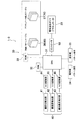
FIG. 6 is a block diagram illustrating a configuration of the
また、制御機構30は、押鍵による鍵10の動作を検出する鍵動作検出手段40を備えている。鍵動作検出手段40は、鍵10の変位を検出する鍵変位検出部41、鍵10の速度を検出する鍵速度検出部42、鍵10の加速度を検出する鍵加速度検出部43によって構成されている。鍵変位検出部41、鍵速度検出部42、鍵加速度検出部43による検出信号は、それぞれA/D変換部44,45,46でデジタル信号に変換されてCPU31に入力されるようになっている。なお、図6では、鍵動作検出手段40として鍵変位検出部41、鍵速度検出部42、鍵加速度検出部43を備える場合を示したが、鍵10の変位のみ、あるいは鍵10の変位と速度のみを検出するのであれば、鍵速度検出部42や鍵加速度検出部43は必ずしも設けなくてもよい。
In addition, the
鍵変位検出部41には、ホール素子を備える変位センサを用いることができる。この変位センサは、図示は省略するが、鍵10に取り付ける磁石と、フレーム3における磁石に対向する位置に取り付けるホール素子とを備えて構成される。この変位センサでは、鍵10の移動による磁石とホール素子の距離の変化によって、磁石からホール素子に入射する磁気が変化し、ホール素子の出力が変化する。したがって、ホール素子の出力を測定することで、磁石とホール素子の距離を算出して鍵10の変位を検出することができる。
For the key
また、鍵変位検出部41の他の例として、グレースケールを備える変位センサを用いることができる。この変位センサは、図示は省略するが、鍵10に取り付けるグレースケールと、フレーム3におけるグレースケールに面する位置に設置する発光素子及び受光素子を備えて構成される。この変位センサでは、発光素子から出てグレースケールを透過あるいは反射した光が受光素子で受光される。その際、押鍵による鍵10の移動によって受光素子で受光される光の光量が変化するので、受光素子の出力に基づいて鍵10の変位を検出することができる。なお、発光素子及び受光素子は、グレースケールに面する位置に設置する以外にも、他の位置に設置した発光素子及び受光素子から光ファイバを延ばし、この光ファイバの先端をグレースケールに向けて配置してもよい。
Further, as another example of the key
鍵速度検出部42としては、コイル及び磁石を備える速度センサを用いることができる。この速度センサは、図示は省略するが、鍵10に取り付ける磁石と、フレーム3における磁石に対向する位置に取り付けるコイルとを備えて構成される。この速度センサでは、押鍵による鍵10の移動によってコイル内部を通過する磁束が変化して、コイルに起電力が発生する。コイルの起電力を測定することで鍵10の速度を検出することができる。
As the key
また、鍵速度検出部42の他の例として、MEMS(Micro Electro Mechanical Systems)ジャイロスコープを備える角速度センサを用いることができる。この角速度センサは、図示は省略するが、鍵10にMEMSジャイロスコープを取り付けて構成される。このMEMSジャイロスコープによって、鍵支点5を中心に回転運動する鍵10の角速度を計測することで、鍵10の瞬間速度を検出することができる。
Further, as another example of the key
鍵加速度検出部43としては、MEMS角加速度センサを用いることができる。MEMS角加速度センサは、図示は省略するが、鍵10に取り付けて使用することができる。このMEMS角加速度センサによって、鍵支点5を中心に回転運動する鍵10の角加速度を計測することで、鍵10の加速度を検出することができる。
As the key
一方、ROM33には、制御パターンテーブル36とアクチュエータ出力テーブル(電圧指令値テーブル)37とが格納されている。図7は、制御パターンテーブル36とアクチュエータ出力テーブル37の概念図である。同図(a)に示す制御パターンテーブル36は、鍵動作(変位、速度、加速度)に応じた鍵10のタッチ感を生じさせるための制御パターンを格納したテーブルであり、鍵動作に対応して電気活性ポリマ20にて発生させる反力(アクチュエータ出力)のパターンを多数格納している。また、同図(b)に示すアクチュエータ出力テーブル37は、アクチュエータ出力に対応する電気活性ポリマ20への印加電圧の指令値(PWM駆動におけるPWM信号のデューティ比)のパターンを多数格納したテーブルである。
On the other hand, the
制御パターンテーブル36とCPU31とで、電気活性ポリマ20にて発生させる反力の情報を出力する反力情報出力手段60が構成されている。また、アクチュエータ出力テーブル37とCPU31とで、反力情報出力手段60からの反力の情報に基づいて電圧指令値を出力する指令値出力手段70が構成されている。
The control pattern table 36 and the
操作部34は、制御パターンテーブル36から参照する制御パターンの設定を入力するために用いられる。表示部35は、設定された制御パターンを表示するために用いられる。なお、操作部34及び表示部35は、鍵盤装置1−3を備える電子楽器が発生する楽音の種類や音色などの設定及び表示を含む他の設定及び表示を行うためにも用いられる。
The
また、鍵盤装置1−3は、電気活性ポリマ20に電圧を印加して電気活性ポリマ20を駆動するコントローラ50を備えている。コントローラ50は、アクチュエータ出力テーブル37から参照された電圧の指令値(PWM駆動におけるPWM信号のデューティ比)に基づいて、電気活性ポリマ20に電圧を印加して、電気活性ポリマ20にて発生する反力を制御するもので、反力制御手段として機能する。
Further, the keyboard device 1-3 includes a
上記構成の鍵盤装置1−3において鍵10のタッチ感を調節する手順を説明する。図8は、この手順を説明するためのフローチャートである。まず、操作部34から鍵10のタッチ感の設定が入力されたか否かを判定する(ステップST1)。鍵10のタッチ感の設定が入力された場合には、押鍵操作による鍵10の移動に応じて、鍵変位検出部41で鍵10の変位(x)を検出する(ステップST2)。また、鍵速度検出部42で鍵10の移動速度(v)を検出する(ステップST3)。また、鍵速度検出部42で鍵10の加速度(a)を検出する(ステップST4)。なお、鍵10の変位(x)のみ、あるいは鍵10の変位(x)と速度(v)のみを検出する場合は、ステップST3やステップST4の手順は省略することが可能である。
A procedure for adjusting the touch feeling of the key 10 in the keyboard device 1-3 having the above configuration will be described. FIG. 8 is a flowchart for explaining this procedure. First, it is determined whether or not the touch setting of the key 10 is input from the operation unit 34 (step ST1). When the setting of the touch feeling of the key 10 is input, the displacement (x) of the key 10 is detected by the key
続いて、反力情報出力手段60は、操作部34から入力されたタッチ感の設定とステップST2〜ステップST4で検出された鍵10の動作とに基づいて、制御パターンテーブル36から参照したいずれかの制御パターンを選択し、この選択した制御パターンに基づいて、電気活性ポリマ20にて発生させる反力(アクチュエータ出力)の情報を出力する(ステップST5)。指令値出力手段70は、反力情報出力手段60からの反力の情報に基づいて、アクチュエータ出力テーブル37から参照したいずれかの電圧指令値(PWM信号のデューティ比)を選択し(ステップST6)、この選択した電圧指令値をコントローラ50に出力する。(ステップST7)。コントローラ50は、この電圧指令値に基づいて、電気活性ポリマ20に電圧を印加して、電気活性ポリマ20にて発生する反力を制御する(ステップST8)。こうして、電圧の印加によって電気活性ポリマ20が変形することで、電気活性ポリマ20から鍵10にかかる反力が変化し、鍵10のタッチ感が変更される。その後、操作部34で入力されたタッチ感の設定に基づいて、引き続き鍵10の動作を検出してタッチ感を調節する必要がある場合は、ステップST2に戻り、ステップST2以降の手順を行う(ステップST9)。
Subsequently, the reaction force
本実施形態の鍵盤装置1−3によれば、鍵動作検出手段40により鍵10の動作を検出し、検出した動作に基づいて電気活性ポリマ20に電圧を印加することで、押鍵操作の途中で鍵10のタッチ感を様々なパターンで変化させることが可能となる。例えば、鍵10が押し下られる間は、電気活性ポリマ20に電圧を印加して鍵10を軽い力で押せるようにし、鍵10が非押鍵位置へ戻るときは、電気活性ポリマ20に印加する電圧をオフにして鍵10を非押鍵位置へ迅速に戻すようにすることができる。また、鍵10が押し下げられる途中で電気活性ポリマ20に印加する電圧を変えれば、鍵10が押し下げられる途中にも鍵10から指にかかる反力を変化させることが可能となる。
According to the keyboard device 1-3 of the present embodiment, the operation of the key 10 is detected by the key
ここで、本実施形態の鍵盤装置1−3における電気活性ポリマ20への電圧の印加による演奏抵抗感の変化について考察する。ここでも、先の図3及び図4に示すモデルを基に考えると、上記の(式3)及び(式5)より、下記の(式7)が導かれる。
![]()
![]()
次に、本実施形態の鍵盤装置1−3におけるタッチ感(演奏抵抗感)の設定の一例を説明する。図9は、従来のグランドピアノにおける押鍵時及び離鍵時の鍵の変位と鍵を押す指にかかる反力との関係を示すグラフである。同図のグラフでは、横軸に非押鍵位置からの鍵の変位を取り、縦軸に指にかかる反力を取っている。なお、同図に示す例では、鍵を等速でゆっくりと移動させた場合に指にかかる反力を測定し、その測定点を曲線状に結んだものを示している。グランドピアノは、移動する鍵によってダンパやハンマなどが順次動かされる構造であるため、同図に示すように、鍵から指にかかる反力は一定ではなく、鍵の移動に伴って変化する。したがって、押鍵操作の途中で鍵のタッチ感が大きく変化する。 Next, an example of setting a touch feeling (performance resistance feeling) in the keyboard device 1-3 according to the present embodiment will be described. FIG. 9 is a graph showing the relationship between the displacement of the key during key depression and key release and the reaction force applied to the finger pushing the key in a conventional grand piano. In the graph of the figure, the horizontal axis represents the key displacement from the non-key-pressed position, and the vertical axis represents the reaction force applied to the finger. In the example shown in the figure, the reaction force applied to the finger when the key is moved slowly at a constant speed is measured, and the measurement points are connected in a curved line. Since a grand piano has a structure in which a damper, a hammer, and the like are sequentially moved by a moving key, as shown in the figure, the reaction force applied from the key to the finger is not constant, and changes as the key moves. Therefore, the touch feeling of the key greatly changes during the key pressing operation.
そこで、本実施形態の鍵盤装置1−3において、図9のグラフに従って電気活性ポリマ20にて発生する反力を変化させるように設定すれば、グランドピアノに近似するタッチ感を得ることが可能となる。このタッチ感の制御パターンを制御パターンテーブル36に格納しておけば、演奏者が操作部34において当該制御パターンを選択することで、グランドピアノに近似した鍵10のタッチ感を簡単に実現できるようになる。
Therefore, in the keyboard device 1-3 of the present embodiment, if the reaction force generated in the
図9に示す例では、グランドピアノにおいて鍵をゆっくりと等速で移動させた場合の反力分布を示しているが、鍵を速く移動させたり、速度を変化させて移動させる場合には、図9に示す例とは異なる反力分布となる。したがって、同じグランドピアノのタッチ感を模したタッチ感の設定でも、押鍵による鍵の速度に応じて反力の制御パターンは異なるものとなる。このため、制御パターンテーブル36には、鍵の動作に基づく多数の制御パターンを格納しておく必要がある。 In the example shown in FIG. 9, the reaction force distribution when the key is slowly moved at a constant speed on the grand piano is shown. However, when the key is moved fast or the speed is changed, The reaction force distribution is different from the example shown in FIG. Therefore, even when setting the touch feeling imitating the touch feeling of the same grand piano, the reaction force control pattern differs depending on the key speed by the key depression. Therefore, it is necessary to store a large number of control patterns based on key operations in the control pattern table 36.
なお、上記の鍵10のタッチ感の設定は一例であり、本実施形態の鍵盤装置1−3では、上記以外にも様々な設定で鍵10のタッチ感を変化させることが可能である。例えば、グランドピアノ以外にも、オルガンなど他の鍵盤装置の演奏抵抗感を模したタッチ感を設定することもできる。また、操作部で操作入力された演奏者の年齢や鍵盤楽器に対する熟練度の情報などに応じて、制御パターンテーブルから制御パターンを参照し、当該演奏者の年齢や熟練度に適応する鍵のタッチ感を実現することも可能である。 Note that the setting of the touch feeling of the key 10 is merely an example, and the keyboard device 1-3 according to the present embodiment can change the touch feeling of the key 10 with various settings other than the above. For example, in addition to the grand piano, it is possible to set a touch feeling imitating the performance resistance of other keyboard devices such as an organ. In addition, the control pattern table is referred to according to the age of the performer input by the operation unit or the skill level information of the keyboard instrument, and the key touch adapted to the player's age and skill level is referred to. It is also possible to realize a feeling.
以上説明したように、本発明の実施形態にかかる鍵盤装置1乃至1−3によれば、押鍵操作に対する反力を発生する反力発生手段として電気活性ポリマ20を用いたので、簡単かつ軽量な構造で鍵10のタッチ感を任意のタッチ感に調節することが可能となる。特に、電気活性ポリマ20は、ソレノイドなどと比較して重量が軽く構造が簡単なので、従来と比較して鍵盤装置の大幅な軽量化、簡素化を図ることが可能となる。
As described above, according to the keyboard devices 1 to 1-3 according to the embodiments of the present invention, since the
以上本発明の実施形態を説明したが、本発明は上記実施形態に限定されるものではなく、特許請求の範囲、及び明細書と図面に記載された技術的思想の範囲内において種々の変形が可能である。なお直接明細書及び図面に記載のない何れの形状・構造・材質であっても、本願発明の作用・効果を奏する以上、本願発明の技術的思想の範囲内である。 Although the embodiments of the present invention have been described above, the present invention is not limited to the above-described embodiments, and various modifications can be made within the scope of the technical idea described in the claims and the specification and drawings. Is possible. It should be noted that any shape, structure, or material not directly described in the specification and drawings is within the scope of the technical idea of the present invention as long as the effects and advantages of the present invention are exhibited.
例えば、反力発生手段である電気活性ポリマ20の設置数や設置位置は、上記実施形態に示すものには限定されず、電気活性ポリマ20は、複数を設置することもできるし、上記以外の位置に設置することもできる。また、上記実施形態で示した電気活性ポリマ20の具体的な形状や構造は一例であり、電気活性ポリマ20は、上記以外の形状や構造とすることも可能である。
For example, the number and positions of the
また、第3実施形態の鍵盤装置1−3では、鍵動作検出手段40として、変位センサと速度センサと加速度センサを備える場合を説明したが、鍵動作検出手段40としては、これ以外にも、押鍵による鍵10の移動に伴って段階的にオンあるいはオフされる複数のスイッチを設置することも可能である。この構成によれば、押鍵あるいは離鍵の際に複数のスイッチのオン・オフ状態を検知することで鍵の変位を検出し、複数のスイッチが順番にオンあるいはオフするタイミング(時間)を検出することで鍵10の速度を検出することができるようになる。 Moreover, in the keyboard apparatus 1-3 of 3rd Embodiment, although the case where a displacement sensor, a speed sensor, and an acceleration sensor were provided as the key motion detection means 40 was demonstrated, as the key motion detection means 40, besides this, It is also possible to install a plurality of switches that are turned on or off in stages as the key 10 is moved by pressing the key. According to this configuration, the key displacement is detected by detecting the on / off state of a plurality of switches when a key is pressed or released, and the timing (time) at which the plurality of switches are sequentially turned on or off is detected. By doing so, the speed of the key 10 can be detected.
1 鍵盤装置
2 底板
3 フレーム
4 鍵支持片
5 鍵支点
6 パネル
7 ストッパー
8 鍵スイッチ
10 鍵
11 駆動片
12 駆動片
20 電気活性ポリマ(反力発生手段)
21 電極膜
22 絶縁膜
30 制御機構
34 操作部
35 表示部
36 制御パターンテーブル
37 アクチュエータ出力テーブル(電圧指令値テーブル)
40 鍵動作検出手段
41 鍵変位検出部
42 鍵速度検出部
43 鍵加速度検出部
44 A/D変換部
45 A/D変換部
46 A/D変換部
50 コントローラ(反力制御手段)
60 反力情報出力手段
70 指令値出力手段
DESCRIPTION OF SYMBOLS 1
21
40 Key
60 Reaction force information output means 70 Command value output means
Claims (5)
前記鍵の押鍵操作に対する反力を発生する反力発生手段と、を備え、
前記反力発生手段は、電圧の印加によって変形する弾性材からなる電気活性ポリマを含んで構成されることを特徴とする鍵盤装置。 A key that is pivotably supported;
Reaction force generating means for generating a reaction force against the key pressing operation of the key,
The keyboard device, wherein the reaction force generating means includes an electroactive polymer made of an elastic material that is deformed by application of a voltage.
前記指令値出力手段から出力された指令値に基づいて前記電気活性ポリマに電圧を印加して前記電気活性ポリマにて発生する反力を制御する反力制御手段と、
を備えることを特徴とする請求項1又は2に記載の鍵盤装置。 Command value output means for outputting a command value of a voltage applied to the electroactive polymer;
Reaction force control means for controlling a reaction force generated in the electroactive polymer by applying a voltage to the electroactive polymer based on the command value output from the command value output means;
The keyboard device according to claim 1, further comprising:
前記指令値出力手段は、前記鍵動作検出手段で検出された前記鍵の動作に基づいて前記電気活性ポリマに印加する電圧の指令値を出力することを特徴とする請求項3に記載の鍵盤装置。 A key operation detecting means for detecting the operation of the key;
4. The keyboard apparatus according to claim 3, wherein the command value output means outputs a command value of a voltage to be applied to the electroactive polymer based on the operation of the key detected by the key action detection means. .
前記指令値出力手段は、前記電気活性ポリマにて発生させる複数の反力に対応する複数の電圧指令値を格納した電圧指令値テーブルを有し、前記反力情報出力手段の出力に基づいて前記電圧指令値テーブルからいずれかの電圧指令値を選択し、該選択した電圧指令値を前記反力制御手段に出力することを特徴とする請求項4に記載の鍵盤装置。 A control pattern table storing a plurality of control patterns relating to the operation control of the key, and selecting one of the control patterns from the control pattern table based on the operation of the key detected by the key operation detecting means; And a reaction force information output means for outputting information of reaction force generated in the electroactive polymer based on the selected control pattern,
The command value output means has a voltage command value table storing a plurality of voltage command values corresponding to a plurality of reaction forces generated by the electroactive polymer, and based on the output of the reaction force information output means 5. The keyboard apparatus according to claim 4, wherein one of the voltage command values is selected from a voltage command value table, and the selected voltage command value is output to the reaction force control means.
Priority Applications (1)
| Application Number | Priority Date | Filing Date | Title |
|---|---|---|---|
| JP2007230292A JP2009063741A (en) | 2007-09-05 | 2007-09-05 | Keyboard device |
Applications Claiming Priority (1)
| Application Number | Priority Date | Filing Date | Title |
|---|---|---|---|
| JP2007230292A JP2009063741A (en) | 2007-09-05 | 2007-09-05 | Keyboard device |
Publications (1)
| Publication Number | Publication Date |
|---|---|
| JP2009063741A true JP2009063741A (en) | 2009-03-26 |
Family
ID=40558376
Family Applications (1)
| Application Number | Title | Priority Date | Filing Date |
|---|---|---|---|
| JP2007230292A Pending JP2009063741A (en) | 2007-09-05 | 2007-09-05 | Keyboard device |
Country Status (1)
| Country | Link |
|---|---|
| JP (1) | JP2009063741A (en) |
Cited By (2)
| Publication number | Priority date | Publication date | Assignee | Title |
|---|---|---|---|---|
| JP2009186580A (en) * | 2008-02-04 | 2009-08-20 | Yamaha Corp | Keyboard device |
| US8420965B2 (en) | 2010-08-17 | 2013-04-16 | Apple Inc. | Button assembly with drive assembly |
-
2007
- 2007-09-05 JP JP2007230292A patent/JP2009063741A/en active Pending
Cited By (3)
| Publication number | Priority date | Publication date | Assignee | Title |
|---|---|---|---|---|
| JP2009186580A (en) * | 2008-02-04 | 2009-08-20 | Yamaha Corp | Keyboard device |
| US8420965B2 (en) | 2010-08-17 | 2013-04-16 | Apple Inc. | Button assembly with drive assembly |
| US8809708B2 (en) | 2010-08-17 | 2014-08-19 | Apple Inc. | Button assembly with drive assembly |
Similar Documents
| Publication | Publication Date | Title |
|---|---|---|
| US8383920B2 (en) | Keyboard apparatus | |
| JP5223490B2 (en) | Force control device for pedal of electronic keyboard instrument | |
| EP2273488B1 (en) | Keyboard apparatus | |
| JP5257086B2 (en) | Electronic musical instrument pedal device | |
| JP5257083B2 (en) | Electronic musical instrument pedal device | |
| JP5422969B2 (en) | Electronic keyboard instrument | |
| JP5428422B2 (en) | Electronic musical instruments | |
| JP5257085B2 (en) | Electronic musical instrument pedal device | |
| JP2009063741A (en) | Keyboard device | |
| JP3772440B2 (en) | Keyboard device | |
| JP5234250B2 (en) | Electronic musical instrument pedal device | |
| WO2017164232A1 (en) | Keyboard device | |
| JP5212024B2 (en) | Electronic keyboard instrument | |
| JP5412990B2 (en) | Keyboard device | |
| JP5532747B2 (en) | Keyboard device | |
| JP6597786B2 (en) | Keyboard device | |
| JP2011237493A (en) | Keyboard device | |
| JP5272439B2 (en) | Force sensor | |
| JP5387164B2 (en) | Keyboard device | |
| JP5724228B2 (en) | Electronic musical instrument pedal device | |
| JP5799867B2 (en) | Pedal device for percussion instruments | |
| JP3910516B2 (en) | Keyboard device | |
| JP5310303B2 (en) | Keyboard device | |
| JP5310304B2 (en) | Keyboard device | |
| JP3743877B2 (en) | Keyboard device |